A dissertation submitted to The University of Tokushima ...
84
Characteristic analysis and suppression strategy of the valve impulse exhaust noise A dissertation submitted to The University of Tokushima for the degree of Doctor of Engineering Science By Jingxiang Li The University of Tokushima June, 2013
Transcript of A dissertation submitted to The University of Tokushima ...

Characteristic analysis and suppression strategy of the valve impulse
exhaust noise
A dissertation submitted to
The University of Tokushima
for the degree of
Doctor of Engineering Science
By
Jingxiang Li
The University of Tokushima
June, 2013


I
Abstract
for thesis entitled
Characteristic analysis and suppression strategy of the valve impulse
exhaust noise
submitted by
Jingxiang Li
for the degree of Doctor of Philosophy
at the University of Tokushima
in July 2013
Pneumatic systems widely exist in the industrial productions, using high pressure compressed
air as power source. The air charging and discharging processes of pneumatic cylinder through
valves are recurrent to generate aerodynamic noise, especially the venting exhaust to atmosphere
directly. In order to suppress this kind of impulse exhaust noise, the characteristics of such noise
and the suppression strategy are presented. The aerodynamic properties of impulse exhaust are
studied firstly. Based on the analysis of aerodynamic parameters during the exhaust process, the
sound sources are discussed. Then the radiated noise of exhaust with a typical sintered bronze
silencer is predicted both in time-domain and frequency-domain. A noise suppression strategy of
controlling the opening process of valve is proposed. Finally the experiments based on a modeled

II
pneumatic exhaust system and a pneumatic friction clutch and brake system of mechanical press are
carried out to verify the validity of the presented model and the suppression strategy.
In Chapter 1, the impulse exhaust noise will be introduced briefly, including the definition,
characteristics and harm to the environment. Then the research background of pneumatic exhaust,
the progress of classical exhaust noise control and the purpose of this study will also be introduced.
In Chapter 2, analysis of aerodynamic properties of impulse exhaust will be presented in
details. The typical pneumatic exhaust systems will be introduced firstly. Then based on some basic
assumptions, the mathematic model of aerodynamic properties of pneumatic exhaust will be
described. A one-dimensional thermodynamic model is used to describe the transient exhaust
process. So the aerodynamic parameters during the exhaust can be obtained, such as cylinder
pressure, mass flow rate. In addition, the movement equation of piston in the cylinder of typical
pneumatic friction clutch and brake system will be introduced to describe the whole systems. In
practice, some classical porous materials are used to reduce the impulse noise. The aerodynamic
model of porous material with rigid frame, such as sintered bronze used in muffler devices normally,
will also be obtained.
In Chapter 3, the sound sources of impulse exhaust noise will be introduced according to the
Lighthill's general theory, as the impulse exhaust noise is a kind of aerodynamic noise. The impulse
exhaust noise is mainly composed of monopole sources related to the mass flow and quadrupole
sources generated by the turbulence. Based on a piston sound source assumption, the noise radiation
characteristics of the exhaust with sintered bronze muffler will be predicted. The mass flow
considered as a monopole source is related to the sound pressure of impulse exhaust noise. And the
sound pressure level (SPL) at a far-field observation point is predicted by the piston acoustic source

III
approximation.
In Chapter 4, the control strategies of impulse exhaust noise will be presented. There are three
approaches to control the noise from the sound source, the propagation path and the receiver,
respectively. Muffler devices are used to reduce the aerodynamic jet noise classically. The features
and disadvantages of various mufflers in the industrial applications will be introduced firstly. Unlike
the steady noise or period noise, the evaluations of impulse noise are introduced. Then a semi-active
control strategy to change the sound source of impulse exhaust by controlling the opening process
of exhaust valve is presented. The principle and specific control method will be introduced.
In Chapter 5, experimental study will be presented. The experiments were based on a
pneumatic friction clutch and brake (PFC/B) system of mechanical press and also a simplified
cylinder exhaust system. In order to test the presented semi-active noise control strategy, a modified
pneumatic valve was designed, which can adjust the poppet valve by a servo motor. The
experimental results will be shown to verify the validity of the presented aerodynamic model and
the radiated noise predictions. The noise was analyzed to study the effect of presented suppression
strategy comparing to the direct exhaust.
In conclusion, the aerodynamic properties of impulse exhaust based on typical pneumatic
exhaust systems have been investigated. According to the aerodynamic models, the flow parameters
during the impulse exhaust were obtained. The sound sources of impulse exhaust noise were studied
based on the Lighthill's general theory of aerodynamic noise. The radiated noise of exhaust with a
typical sintered bronze silencer is predicted both in time-domain and in frequency-domain. In
addition, a semi-active noise control strategy has been presented to suppress the impulse exhaust
noise especially to reduce the peak SPL.

IV

V
CONTENTS
Chapter 1 Introduction ........................................................................................................................................... 1
1.1 Properties of impulse exhaust noise ......................................................................................................... 1
1.1.1 Brief description of impulse exhaust noise ................................................................................... 2
1.1.2 Harm of impulse exhaust noise ...................................................................................................... 4
1.2 Research background ................................................................................................................................ 6
1.2.1 Pneumatic systems .......................................................................................................................... 6
1.2.2 Mechanism study of impulse exhaust noise .................................................................................. 7
1.2.3 Progress of exhaust noise control................................................................................................. 10
1.3 Thesis organization .................................................................................................................................. 12
1.3.1 Scope .............................................................................................................................................. 13
1.3.2 Signification ................................................................................................................................... 13
Chapter 2 Aerodynamic properties of impulse exhaust ..................................................................................... 15
2.1 Typical pneumatic exhaust systems ........................................................................................................ 15
2.2 Mathematic model description ............................................................................................................... 18
2.2.1 Model assumptions ....................................................................................................................... 18
2.2.2 Thermodynamic equation of control volume ............................................................................. 19
2.2.3 Mass flow rate ............................................................................................................................... 20
2.2.4 Dynamic equation of piston ......................................................................................................... 23
2.3 Model of porous material with rigid frame ........................................................................................... 24
2.4 Aerodynamic model of pneumatic exhaust systems .............................................................................. 27
Chapter 3 Sound sources and noise radiation analysis ...................................................................................... 29
3.1 Lighthill's general theory of aerodynamic noise ................................................................................... 29
3.2 Prediction of radiated exhaust noise ...................................................................................................... 31
3.2.1 Piston acoustic source ................................................................................................................... 31
3.2.2 Model of sintered bronze silencer ................................................................................................ 32
3.2.3 Prediction of radiated exhaust noise ........................................................................................... 34
Chapter 4 Strategies of impulse exhaust noise suppression ............................................................................... 37
4.1 Classical control strategy ........................................................................................................................ 37
4.2 Semi-active control strategy .................................................................................................................... 38
4.2.1 Evaluations of impulse noise ........................................................................................................ 38
4.2.2 Principle ......................................................................................................................................... 41
4.2.3 Control method ............................................................................................................................. 44
Chapter 5 Experimental study.............................................................................................................................. 45
5.1 Experimental apparatus .......................................................................................................................... 45
5.1.1 PFC/B test-bed .............................................................................................................................. 45
5.1.2 Modified pneumatic valve ............................................................................................................ 46
5.1.3 Simplified cylinder exhaust test-bed ........................................................................................... 47
5.2 Results of aerodynamic model ................................................................................................................ 48
5.2.1 Direct exhaust without silencer .................................................................................................... 49
5.2.2 Exhaust with sintered bronze silencer ........................................................................................ 51
VI
5.3 Results of radiated noise prediction ....................................................................................................... 53
5.3.1 Noise prediction in time-domain .................................................................................................. 53
5.3.2 Noise spectrum prediction ............................................................................................................ 54
5.4 Results of impulse exhaust noise suppression........................................................................................ 56
5.4.1 Exhaust with normal solenoid valve ............................................................................................ 56
5.4.2 Exhaust with modified valve ........................................................................................................ 58
5.4.3 Discussions of noise suppression .................................................................................................. 62
Chapter 6 Conclusions and future work .............................................................................................................. 67
6.1 Main conclusions ...................................................................................................................................... 67
6.2 Future work .............................................................................................................................................. 68
References ............................................................................................................................................................... 69
Acknowledgement .................................................................................................................................................. 73
Publications ............................................................................................................................................................ 75

- 1 -
Chapter 1 Introduction
Pneumatic systems widely exist in the industrial productions, using high pressure compressed
air as power source. The air charging and discharging processes of pneumatic cylinder through
valves are recurrent to generate aerodynamic noise, especially the venting exhaust to atmosphere
directly[1-5]. The transient exhaust is choked and sonic at the valve throat since the high pressure of
compressed air larger than 0.3 MPa normally[6-8]. During the exhaust process, the potential energy
of compressed air in the cylinder is converted to kinetic energy while the air flow is accelerated
through the valve generating the impulse exhaust noise with short duration. The sound pressure of
impulse exhaust noise is changed acutely because of the rapid flow change via the valve. It will
cause serious environment pollution and hearing damages for workers due to the large sound
pressure of exhaust noise with the peak value normally more than 130 dB. Thus, several researches
both on the mechanism and reduction methods of air exhaust noise were studied in recent
years[9-12].
1.1 Properties of impulse exhaust noise
As indicated in the previous statement, the impulse exhaust noise is a kind of aerodynamic
noise generated by the unsteady jet. According to the noise fluctuation value, exhaust noise is
divided into steady exhaust noise, periodical exhaust noise and intermittent or impulse exhaust
noise. As a special jet noise, the impulse exhaust noise is also caused by high-velocity jets and the
turbulent eddies generated by shearing flow. Such noise is known as broadband noise and extends
well beyond the range of human hearing. The sound generated by high-speed jets is usually

- 2 -
associated with several different he sound generated by high-speed jets is usually associated with
several different sources acting simultaneously, such as jet mixing noise caused by the turbulent
mixing of the jet with the ambient medium, and shock-associated noise for imperfectly expanded
supersonic jets produced by the convection of turbulence through shock cells in the jet[1,13].
Different from the normal steady jet noise and periodical jet noise, the impulse exhaust noise has a
significant impulse property.
1.1.1 Brief description of impulse exhaust noise
Impulse noise was first introduced by Rosenblith and Stevens[14]. From the results of
theoretical and experimental investigations, they argued that some judgment is required to
distinguish between impulse and continuous noise[15,16]. Figure 1 schematically types the
pressure-time histories of these noises. Steady noise has a nearly constant pressure level at a
measuring point with no or only extremely small fluctuations. Unsteady noise has irregular and
continuous signals over a wide range of sampling period. Of the signals that intermittently arise at a
time interval, intermittent noise has the duration time of each pulse signal over several seconds. The
intervals between the pulse signals may be nearly constant or irregular. The definition of impulse
noise varies from country to country and there is still no consistent definition. A recommendation
from the International Standard Organization ISO2204 stated that an impulse noise can be
characterized as a burst sound or continuous burst sounds with a duration time less than one
second[17]. This indicates that if an impulse noise is produced within the time interval mentioned
above, an adjustment should be necessary to find the equivalent sound pressure level. On the other
hand, IEC argued that an impulse noise can be a single-pulse sound or a burst sound with a duration

- 3 -
time between 0.001 and 1 s[18]. Anyway, the exhaust noise studied in this paper belongs to impulse
noise.
Figure 1-1[19] Classification of noises based on the pressure-time histories.
In this paper, impulse noise is defined as a short-duration sound characterized by a shock front
pressure waveform (i.e. virtually instantaneous rise), usually created by a sudden release of energy;
for example, as encountered with explosives or gun blasts[1]. Such a characteristic impulse pressure
waveform is often referred to as a Friedlander wave, and is illustrated in Figure 1-2(a). This single
impulse waveform is typically generated in free-field environments, where sound reflecting surfaces
that create reverberation are absent. With gunfire, mechanically generated noise is also present in
addition to the shock pulse, and in this case the waveform envelope can take the form illustrated in
Figure 1-2(b).
The durations of impulsive noises may vary from microseconds up to 50 ms, although in
confined spaces reverberation characteristics may cause the duration to extend considerably longer.
In all cases, however, the characteristic shock front is present. For the purpose of assessing hearing
damage risk, a duration time has been defined as the time required for the peak level to drop 20 dB,
as illustrated in Figure 1-2.

- 4 -
Figure 1-2[1] Idealized waveforms of impulse noise. Peak level is the pressure difference AB; duration time is the
time difference AD (+EF when a reflection is present).
Pneumatic devices quite often eject gas (air) in the form of high-pressure jets. Such jets can be
very significant generators of noise. Different from the combustion engine exhausts, there are many
kinds of exhaust is a transient process, such as the exhaust of pneumatic friction clutch and brake
(PFC/B) cylinders. In the practical work, the exhaust process is very short to ensure the
coordination of the PFC and PFB. Furthermore, such kind of pneumatic exhaust has characteristics
of high-pressure exhaust (pressure ratio normally more than 3) and large gas displacement. Thus, it
will generate huge impulse noise of as high as 125 dB(A), with the peak sound pressure more than
130 dB(A) [3].
1.1.2 Harm of impulse exhaust noise
Industrial noise is usually considered mainly from the point of view of environmental health
and safety, rather than nuisance, as sustained exposure can cause permanent hearing
damage[1,13,20]. Exposure to excessive noise for a short period of time may produce a temporary
loss of hearing sensitivity. If this happens, the subject may notice a slight dulling in hearing at the
end of the exposure. This effect is often accompanied by a ringing in the ears, known as tinnitus,

- 5 -
which persists after the noise exposure. This temporary loss of hearing sensitivity is known as
temporary threshold shift (TTS) or auditory fatigue. Removal from the noise generally leads to
more or less complete recovery if the exposure has not been too severe. If the noise exposure is
severe or is repeated sufficiently often before recovery from the temporary effect is complete, a
permanent noise-induced hearing loss may result.
The elevated sound levels cause trauma to cochlear structure in the inner ear, which gives rise
to irreversible hearing loss. A very loud sound in a particular frequency range can damage the
cochlea's hair cells that respond to that range, thereby reducing the ear's ability to hear those
frequencies in the future; however, loud noise in any frequency range has deleterious effects across
the entire range of human hearing. The outer ear (visible portion of the human ear) combined with
the middle ear amplifies sound levels by a factor of 20 when sound reaches the inner ear.
Noise can not only cause hearing impairment (at long-term exposures of over 85 dB(A),
known as an exposure action value), but it also acts as a causal factor for stress and raises systolic
blood pressure. Additionally, it can be a causal factor in work accidents, both by masking hazards
and warning signals, and by impeding concentration.
In general, people are not habitually exposed to impulsive noises. In fact, only people exposed
to explosions such as quarry blasting or gunfire are exposed to impulse noises. Estimates of the
number of pulses likely to be received on any one occasion vary between 10 and 100, although up
to 1000 impulses may sometimes be encountered.
The noise level below which damage to hearing from habitual exposure to noise should not
occur in a specified proportion of normal ears is known as the hearing damage risk criterion.
Internationally, the hearing damage risk criterion has been set at 90 dB(A) for a continuous

- 6 -
eight-hour exposure each day to ordinary broadband noise. Moreover a criterion of 85 dB(A) for an
eight-hour daily exposure is encouraged to minimize the hearing loss in some criterions. To the
impulse noise, the criterion is related to the exposure impulse numbers every day. The acceptable
numbers of impulse noise of 140 dB and 130 dB are 100 and 1000, respectively[3].
1.2 Research background
As the previous statements, the impulse exhaust noise has a serious pollution to the
environment and harm to people. In this section, the common pneumatic systems generating the
exhaust noise would be introduced. The mechanism study of impulse exhaust noise would be
presented. It would be also presented the outstanding studies on the exhaust noise control.
1.2.1 Pneumatic systems
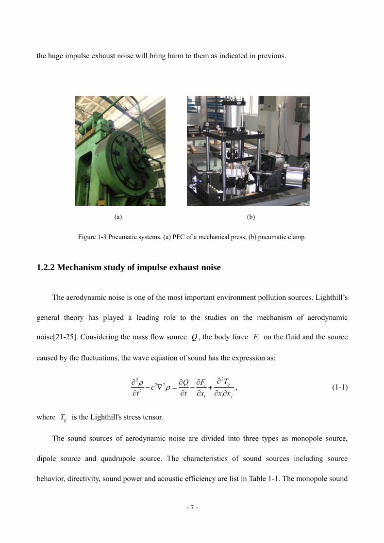
The pneumatic systems such as PFC/B systems and pneumatic clamps shown in figure 1-3 are
widely exist in the industrial applications. The intake and exhaust processes are controlled by a
pneumatic directional valve. When the high pressure air is supplied into the PFC cylinder, the piston
will be pushed to joint the friction disk so that the slider-crank mechanism will be driven by the
main motor. When the valve is switched to vented the air inside the cylinder, the piston will be
returned by the returning spring and unclench the friction disk. In the practical work, the air
pressure supplied into the cylinder normally more than 0.5 MPa, so the sonic choked exhaust will
happens during the exhaust process. As same as the PFC/B systems, the pneumatic clamp works by
injecting and exhausting the air of cylinder alternately, so that the work piece could be clamped and
unclenched. In the production process, workers are normally beside the equipment or devices, thus
- 7 -
the huge impulse exhaust noise will bring harm to them as indicated in previous.
(a) (b)
Figure 1-3 Pneumatic systems. (a) PFC of a mechanical press; (b) pneumatic clamp.
1.2.2 Mechanism study of impulse exhaust noise
The aerodynamic noise is one of the most important environment pollution sources. Lighthill’s
general theory has played a leading role to the studies on the mechanism of aerodynamic
noise[21-25]. Considering the mass flow source Q , the body force iF on the fluid and the source
caused by the fluctuations, the wave equation of sound has the expression as:
222 2
2,iji
i i j
TFQc
t t x x x
(1-1)
where ijT is the Lighthill's stress tensor.
The sound sources of aerodynamic noise are divided into three types as monopole source,
dipole source and quadrupole source. The characteristics of sound sources including source
behavior, directivity, sound power and acoustic efficiency are list in Table 1-1. The monopole sound

- 8 -
source is related to the mass flow rate at the exhaust outlet. The sound power of monopole is
2 4 2 2 3 2m 0 0 0 .W v D c v D M (1-2)
where v is the exhaust velocity, D is the diameter of outlet, and c are the density and sound
speed of exhaust air, 0 and 0c are the density and sound speed of surrounding air, M is the
Mach number.
The dipole sound source is related to the force of flow and solid body. It can be seen as
composed by two monopoles. The sound power of dipole source is the form as:
2 6 2 3 2 3 2 3d 0 0 0 .W v D c v D M (1-3)
When the flow velocity is very high, the Lighthill's stress tensor ijT is changed in the flow
field to generate quadrupole sound source. It can be seen as a pair of 180˚ phase dipoles. The
radiated sound power is the expression as:
2 8 2 5 2 3 2 5q 0 0 0 .W v D c v D M (1-4)
Table 1-1 Three types of basic sound sources
Source
type
Source behavior Directivity Sound power ratio
Acoustic
efficiency ratio180˚ phase difference
Monopole
2 4 2 2 3 20 0 0v D c v D M M
Dipole
2 6 2 3 2 3 2 30 0 0v D c v D M M3
Quadrupole
2 8 2 5 2 3 2 5
0 0 0v D c v D M M5

- 9 -
In the exhaust process of PFC/B systems, the transient exhaust is choked and sonic exhaust
occurs at the throat (Mach number equals to 1) most of the time since the initial pressure in cylinder
is usually more than 0.3 Mpa [26-30]. Maa [6] indicated that as the pressure ratio between 3 to 5
particularly, the noise generated by transient exhaust is entirely dominated by impulsive noise. The
noise always more than 120 dB mainly contains in high-frequency because of the impulse
characteristic [7-9]. Sintered bronze silencer is always used to suppress this kind of exhaust noise.
Besides reducing the noise, the aerodynamic property of silencer is also an important factor of the
equipment for the normal and safe operation [7]. The descriptions of pressure drop in the porous
materials have been studied for decades. Ergun equation, one of the descriptions, was first given by
Ergun [31] and then verified and developed by many later workers [32-35]. For high velocity flow,
both the viscous energy loss, proportional to the superficial velocity and the correction for inertial
losses in the porous medium are considered. It originally describes the relationship between the
pressure drop and the parameters of porous medium composed of spherical particles such as
porosity and particle diameter.
According to Lighthill sound analogy [21,22], the transient exhaust noise is mainly composed
of monopole sources related to the mass flow and quadrupole sources generated by the turbulence
[9,28]. Therefore the flow generated noise is closely related to the aerodynamic parameters of the
transient exhaust. Zhao et al. [9] applied the Lighthill’s aerodynamic noise generated theory to
predict the intermittent exhaust noise with expansion chamber muffler, and the results were close to
the experiments at high-frequency. Shi [7] furthermore considered the transient flow at the outlet of
ducts as an approximating piston acoustic source and analyzed the octave spectrum of the exhaust
noise without silencers, of which the errors were less than 3.5 dB from 250 Hz to 16 kHz. The

- 10 -
acoustic propagation and absorption properties of porous materials are described first by Kirchhoff
with a phenomenological model of viscous and thermal effects created in cylindrical tubes with
circular cross-section [36]. In addition, the macroscopic description by two parameters, namely, the
effective density and bulk modulus (or compressibility) is used to predict the sound absorbing
performance of porous materials with complex geometry. Johnson-Champoux-Allard model, the
widely accepted and used theoretical model, presents a description assuming the porous layer as an
equivalent fluid. The formulation of effective density is proposed by Johnson et al. [37] and
improved by Pride et al. [38] to express the dynamic viscous permeability. Similar descriptions of
thermal exchanges related to Bulk modulus is modeled by Champoux and Allard [39] and Lafarge
et al. [40] later. Based on the equivalent models, the classical transfer matrix method (TMM) is
often used to obtain the acoustic properties of a certain porous material or multilayer materials
conveniently and rapidly [41-43]. Moreover, impulsive excitations generated the discharge from a
high pressure air tank were used for the prediction of acoustic response of absorbent material using
the characteristic impedance and wavenumber [44-46].
1.2.3 Progress of exhaust noise control
Until now, reduction of impulse noise due to pneumatic exhaust has largely been achieved by
passive devices. Muffling devices or silencers are commonly used to reduce noise associated with
internal combustion engine exhausts, high pressure gas or steam vents, compressors and fans. These
examples lead to the conclusion that a muffling device allows the passage of fluid while at the same
time restricting the free passage of sound. Muffling devices may function in any one or any
combination of three ways: they may suppress the generation of noise; they may attenuate noise

- 11 -
already generated; and they may carry or redirect noise away from sensitive areas.
Since 1950s, the reactive mufflers were studied to reduce the noise in industrial. The expansion
chamber and side branch resonator were used in the exhaust noise suppression. Four terminal
parameter method evolved from the equivalent circuit improved the study of acoustic characteristics
of the reactive devices[47-49]. Furthermore, many works also researched the properties of such
reactive devices with flow. However, these studies were almost based on the noise control with
steady flow conditions. Later, finite element method (FEM) and boundary element method (BEM)
were used to simulate the sound field inside the mufflers, and obtain the properties such as
transmission loss.
The investigation of active noise control theory was developed and studied by many workers
since 1960s. This method has a significant suppression on the one-dimensional noise of specific
frequency such as noise generated by steady flow; but is difficult to reduce the high-frequency
noise[50,51].
In order to reduce the pneumatic exhaust noise, various mufflers were designed as shown in
Figure 1-4[12,52-56]. Expansion chamber mufflers as the simplest reactive muffler suddenly
expand and reduce the cross-section area to reflect the sound wave back to the source and reduce
the amount of acoustic energy transmitted. They have good performance at low frequencies and are
useful in harsh environments. Unlike reactive mufflers, absorptive mufflers which incorporate
sound absorbing porous materials such as fiberglass, mineral wool and high-porosity foams to
transform acoustic energy into heat. Absorbing materials have some disadvantages including
pollution, the risk of high heat and limited lifetime therefore they may become ineffective and
impractical. Nevertheless, the porous mufflers are widely used in the pneumatic exhaust noise

- 12 -
reduction because of the desirable characteristics for broadband noise. Perforated panel with wide
absorption sound spectrum and high sound absorption coefficient was studied and applied to
suppress the industrial noise in recent decades. The low back pressure characteristic of perforated
panel ensures the air being expelled smoothly. In the application of IEN control, the noise reduction,
the flow resistance and the structure cost should be all considered as the evaluations of muffler.
(a) (b)
(c) (d) (e)
Figure 1-4[12] Various muffler devices. (a) Expansion chamber muffler; (b) perforated panel muffler;
(c) Foam plastic muffler; (d) Polyethylene resin muffler; (e) sintered bronze muffler.
1.3 Thesis organization
In this dissertation, the aerodynamic properties and radiated noise characteristics of impulse
exhaust would be studied. The aerodynamic model of impulse exhaust was presented. The sound

- 13 -
sources of impulse exhaust noise and the radiated noise prediction was also introduced. Then a
semi-active noise control strategy was proposed to suppress the peak SPL of impulse exhaust noise.
The experiments were carried out to verify the presented models and noise control strategy.
1.3.1 Scope
1. Modeling the impulse exhaust process as an initial value problem for ordinary differential
equations.
2. Investigate the aerodynamic properties of porous material with rigid frame such as sintered
bronze material by Ergun equation.
3. Predict the radiated noise generated by exhaust with a sintered bronze silencer according to
a piston sound source approximation.
4. A semi-active noise control strategy by controlling the opening process of valve was
investigated. In order to verify the strategy, a modified valve driven by a servo motor was
designed and tested in a pneumatic cylinder exhaust system.
1.3.2 Signification
1. The mathematic model of aerodynamic properties of impulse exhaust based on
thermodynamics can be solved conveniently. Combing the model of porous material with
rigid frame, it can help to analyze and improve the aerodynamic properties of various
silencers.
2. According to the presented radiated noise characteristics and piston sound source
approximation, the radiated exhaust noise at far field can be predict both in time-domain and

- 14 -
in spectrum.
3. The effect of effective cross-sectional area of valve on the impulse exhaust noise was
investigated. According to the proposed noise control strategy, the sound source of impulse
exhaust noise will be changed so that the noise can be suppressed especially reducing the
peak SPL.

- 15 -
Chapter 2 Aerodynamic properties of impulse exhaust
In this chapter, analysis of aerodynamic properties of impulse exhaust will be presented in
details. The typical pneumatic exhaust systems will be introduced firstly. Then based on some basic
assumptions, the mathematic model of aerodynamic properties of pneumatic exhaust will be
described. A one-dimensional thermodynamic model is used to describe the transient exhaust
process. So the aerodynamic parameters during the exhaust can be obtained, such as cylinder
pressure, mass flow rate. In addition, the movement equation of piston in the cylinder of typical
pneumatic friction clutch and brake system will be introduced to describe the whole systems. In
practice, some classical porous materials are used to reduce the impulse noise. The aerodynamic
model of porous material with rigid frame, such as sintered bronze used in muffler devices normally,
will also be obtained.
2.1 Typical pneumatic exhaust systems
Pneumatic systems are normally applied to thrust control, flow control and pressure control.
Figure 2-1 shows a pneumatic exhaust system, including a cylinder, a pneumatic valve, exhaust
pipes and a silencer. The cylinder in Figure 2-1 is a kind of acting cylinder, which is a typical
application of pneumatic friction clutch and brake (PFC/B). It is composed of a cylinder, a piston
and a returning spring. When the high pressure compressed air is supplied from compressor to the
acting cylinder, the piston is pushed to the left side as the position shown in Figure 2-1 so the
friction disc is engagement. Meanwhile the exhaust passage is opened, allowing the air in the
cylinder to be discharged from port A to port R. The pressure in the cylinder is reduced so that the

- 16 -
piston will be reset by the returning spring and the friction disc will be disengagement. The high
pressure air exhausts through the pipes, hybrid regulator valve and silencer to the environment
immediately, and generates flow noise.
P
R
A
Pneumatic valve
0 x0 x
Silencer
Cylinder
PistonReturning spring
pa
p1, V1
ρ1, T1
High pressure air from compressor
Pipes
Pipes
Figure 2-1 Structure of a typical pneumatic exhaust system.
The pneumatic valve used in the exhaust systems is normally a 3/2-way directional valve or a
quick exhaust valve. The directional valve allows air flow into different paths from. It usually
consist of a spool inside a cylinder which is mechanically or electrically controlled. The movement
of the spool restricts or permits the flow, thus it controls the fluid flow. These valves make use of
electromechanical solenoids for sliding of the spool. In order to facilitate the study, a hybrid
regulator valve VY1700 produced by SMC Company shown in Figure 2-1 and a common 3/2 way
directional valve K23J50 are used in this study. The hybrid regulator valve is created from a
regulator and a solenoid valve. It is not only able to switch the flow paths, but also able to adjust the
cylinder pressure by the regulator. The schematic diagram of VY1700 is shown in Figure 2-2[57].
Then the working principle of VY1700 will be introduced.

- 17 -
F
F
Figure 2-2 Schematic diagram of VY1700 valve. It includes 1-pilot valve, 2-body, 3-cover, 4-adjusting piston,
5-spring, 6-valve guide, 7-poppet valves, 8-shaft and 9-valve guide
The pair of poppet valves closes due to the balance between actuating forces F1 and F2. When
the port A pressure becomes higher than the pilot pressure, F2 becomes higher than F1. This causes
the pressure regulation piston to move upward, and the top poppet valve to open, allowing the air to
be discharged from port A to port R. When the port A pressure drops to reach a balance, the
regulator returns to the state shown in the Figure 2-2.
The working principle of K23J50 3/2-way directional valve is very simple. When the pilot
valve is opened to supplied high pressure air into pilot cylinder, the poppet valve is pushed to move,
allowing the air to be supplied from port P to port A. Conversely, when the pilot valve is closed to
discharge the air in the pilot cylinder, the poppet valve is returned, closing the intake path, and
allowing the air to be discharged from port A to port R.
- 18 -
2.2 Mathematic model description
In order to study the unsteady flow of pneumatic exhaust process, the control volume approach
is introduced to establish the mathematic model. In fluid mechanics and thermodynamics, a control
volume is a mathematical abstraction employed in the process of creating mathematical models of
physical processes. In an inertial frame of reference, it is a volume fixed in space or moving with
constant velocity through which the fluid (gas or liquid) flows. The surface enclosing the control
volume is referred to as the control surface. Combining the energy equation, the mass balance
equation and the characteristic equation of the gas, the parameters in the control volume can be
determined while considering the exchange of heat and work done at the control surfaces.
2.2.1 Model assumptions
Considering the actual situation of pneumatic exhaust process, some assumptions are given in
details in order to facilitate the study of aerodynamic characteristics[58-63].
(1) During the pneumatic exhaust process, the gas energy is instantaneously and uniformly in
the total volume of cylinder. So the exhaust process is assumed to be quasi-static.
(2) The exhaust process is very short so that the exchange of heat at the walls of cylinder, pipes
and valve can be neglected. The exhaust process in the pneumatic exhaust system can be
approximated as an adiabatic process, and furthermore be assumed to be isentropic.
(3) Due to the cross-sectional area of cylinder is much larger than that of pipes or valve, the
velocity of air in the cylinder can be ignored during the exhaust process.
(4) The air flow in the cylinder and pipes is regarded as one-dimensional flow.
(5) The air flow through the pneumatic valve can be approximated as air in the large container

- 19 -
or a large section of pipe flows through a convergent nozzle to the after chamber or environment, as
shown in Figure 2-3.
(6) The pressure loss caused by the friction of air flow through the pipes is corrected by
cross-sectional area.
Figure 2-3 Simplified model of air flow through a pneumatic valve.
2.2.2 Thermodynamic equation of control volume
The compressed air in the system can be regarded as perfect gas. According to the first law of
thermodynamics, the change in internal energy of the compressed air inside the cylinder or the
muffler’s chambers, of which the volume is seemed as a control-volume, is written as [64-66]:
0in in 0out outδ δ δ δ δ ,E Q W h m h m (2-1)
where E is the energy of the control-volume, and δQ and δW are the heat added to the system
and the work done by the system. The last two terms of Equation (2-1) are the energy of the mass
flow in and out of the control volume. Assuming the parameters in the control volume are pressure
cp , volume cV , density c , temperature cT , mass cm and internal energy c c / ( 1)e RT . The

- 20 -
differential energy inside the control volume is expressed by:
c c c cc c
d( ) d dd 1( ) ,
d d 1 d d
m e V pEp V
t t t t
(2-2)
according to the perfect gas equation and isentropic condition, where is the adiabatic coefficient
of the perfect gas, R is the gas constant. Substituting the stagnation enthalpy
0 0 0 / ( 1) ph c T RT , the sound velocity c RT and the Equation (2-2) into the Equation
(2-1), the thermodynamic differential equation in the control volume can be rewritten as:
2 2c c outinc c 0in 0out
d d dd.
d d d d
p V mmV p c c
t t t t (2-3)
Particularly, if the volume of control volume is fixed, such as a fixed volume cylinder or the
chamber of silencer, Equation (2-3) will be simplified to the following form.
2 2c outinc 0in 0out
d dd.
d d d
p mmV c c
t t t (2-4)
In order to solve the state parameters of control volume during the unsteady exhaust process,
the mass flow rate flow in and out of the control volume should be obtained firstly. In addition, the
mass flow rate flowing out should be equal to the mass flow rate flowing in the after adjacent
control volume because of the continuity of mass.
2.2.3 Mass flow rate
The air flowing through a pneumatic valve is seem as flowing through a convergent nozzle as
shown in Figure 2-3. It is assumed that the stagnation parameters of air in chamber Ⅰ are 1p , 1 ,
1T , the parameters of air in chamber Ⅱ are 2p , 2 , 2T , the parameters at the throat of nozzle are

- 21 -
ep , e , eT , and the effective cross-sectional area of the convergent nozzle is eS . The quasi-static
equation of the flow energy at the nozzle throat is:
2 2 21 e e
1,
2c c u
(2-5)
where eu denotes the velocity of air flow through the nozzle. The mass flow rate through the
convergent nozzle is e e ed / dm t u S .
1) Sonic exhaust
When the pressure in chamber Ⅰ is larger than the critical value related to the pressure in
chamber Ⅱ as /( 1)
1 2( 1) / 2p p , sonic flow happens at the throat of nozzle. The pressure at
the nozzle throat is proportional to 1p as /( 1)
e 12 / ( 1) p p
. The mass flow reaches
maximum and the velocity of exhaust flow at the throat reaches the sound speed, so the Mach
number is equal to 1. Substituting the Mach number e e/ 1aM u c into Equation (2-5), the flow
velocity at the throat can be obtained as:
1 2
1
2.
1eu RT
(2-6)
Therefore, the mass flow rate at the nozzle throat of sonic exhaust is written as:
1
2( 1)
11
2.
1
d
d eS pR
m
Tt
(2-7)
2) Subsonic exhaust
When the pressure in chamber Ⅰ is smaller than the critical value related to the pressure in
chamber Ⅱ as /( 1)
1 2( 1) / 2p p , subsonic flow happens at the throat of nozzle. The
pressure at the nozzle throat is equal to the back pressure as e 2p p . So the flow velocity and the

- 22 -
mass flow rate at the throat are written as:
1
1 2
1
21 ,
1e
RT pu
p
(2-8)
2 1
2 21
1 1 1
2
1
d
d.e
p pS
RT pt p
mp
(2-9)
3) The effective cross-sectional area of valve
In the previous discussions, the effective cross-sectional area eS of nozzle throat is a constant.
However, the opening process of valve is dynamic so that eS is a variable of time during the opening process of
valve in practice. Thus, it is necessary to establish the mathematic model of variable e ( )S t .
To the common directional valve as K23J50, when the pilot valve opens, the poppet valve is
reset by the force of returning spring and cylinder air in a very short time. Assuming the
displacement of poppet valve is linear in the total opening time 0t , and the maximum
cross-sectional area is e, maxS , the effective cross-sectional area of valve can be written as:
e, max 0 0
ee, max 0
/ ,( ) .
,
S t t t tS t
S t t
(2-10)
To the hybrid regulator valve VY1700, the effective cross-sectional area eS is a function of
the cylinder pressure or the port A pressure p and the response time 0t of the hybrid regulator
valve. Assuming that the area eS is related linearly to the port A pressure p , the effective
cross-sectional area of valve can be written as[8]:
0 0e
0
( ) / ,( ) ,
,
ap b t t t tS t
ap b t t
(2-11)

- 23 -
where a and b are related to the parameters of returning spring, poppet valve and adjusting
piston inside VY1700 valve. When the port A pressure is equal to the ambient pressure, the flow
path between port A and port R is close causing by the force of returning spring.
2.2.4 Dynamic equation of piston
The exhaust process of a fixed volume cylinder through pneumatic valve can be described by
the above equations. But to the acting cylinder as shown in Figure 2-1, the piston will be moved
when the cylinder pressure drops. Thus, the volume of acting cylinder is variable. Neglecting the
friction and viscous force, the dynamic equation of piston is
2
0 a 1 2
d( ) ( ) ,
d
xk x x p p S M
t (2-12)
where x is the displacement of piston, M and S are the mass and cross-sectional area of the
piston, k and 0x are the stiffness and pre-compression length of the returning spring. Assuming
the initial volume before exhaust is 0V , the variable volume will be 1 0V V xS . Therefore
Equation (2-12) can be rewritten as:
221
1 a 1 0 02
d( ) ( )
d
VM p p S k V V x S
t (2-13)
Equation (2-12) or (2-13) is only used to describe the dynamic process of piton moving. When
the cylinder pressure is large enough as 1 a 0 /p p kx S , the piston is pressed at the left limit
position and the cylinder volume keeps 1 0V V . Also, when the piston is reset to the right limit
position x when the solved piston displacement x x , the cylinder volume also becomes to a fixed
value 1 0V V x S .

- 24 -
2.3 Model of porous material with rigid frame
Using the mathematic model presented above, it can establish some simple pneumatic exhaust
system with expansion chamber muffler while seeming the connections between expansion
chambers also as convergent nozzle. But in the dissipative mufflers, porous materials are always
used to enhance the effect of sound absorption because of their favorable acoustic absorbing
properties for suppressing noise [67]. Then a simple model of porous material with rigid frame is
introduce.
Figure 2-4 Micrographic surface of sintered bronze material. Note that the mean diameter of bronze particles is
320 μm, and the mean radius of pores is 50 μm.
As shown in Figure 2-4, the sintered bronze is a very common rigid porous material which is
widely used to make silencers for the flow noise reduction. Differing from the traditional porous
materials such as foams and mineral wool, sintered bronze retains the properties of metal such as
heat transfer, high specific stiffness and intensity. It is particularly suitable for industrial
applications under extreme conditions. The sintered bronze muffler is always sintered by the
uniform bronze particles and is porosity allowing the air to flow through smoothly. Some

- 25 -
assumptions are listed as follows.
(1) It is isotropy inside the sintered bronze porous materials, and fully interconnected between
all of the holes.
(2) The bronze particles are sphere with same size, ignoring the irregular shape and
inhomogeneous distribution of particles.
(3) The sintered bronze materials are rigid both of the frame and the inside pore structure.
In order to study the aerodynamic properties of porous materials, Darcy-Forchheimer model is
widely used to describe the relationship between pressure drop and flow velocity as the follow:
2s 2 s
Δ 1,
2
pv C v
L
(2-14)
where Δ /p L is the pressure drop per unit length of the porous material, and are the
dynamic viscosity and density of air, sv is the superficial velocity (the average velocity over the
flow cross-section), is the permeability coefficient and 2C is the inertial resistance factor. The
dynamic viscosity can be obtained by Sutherland’s formula.
Ergun equation is one form of Equation (2-14) which is widely used in the packed bed research
of chemical engineering. For sintered bronze, the permeability and inertial resistance factor 2C
can be described as follows[31]:
2 3p
22 3p
3.5 (1 ),
150 (1 )
DC
D
, (2-15)
where is the void fraction or the porosity (the ratio of the void volume and the total volume of
the porous media), and pD is the mean particle diameter about 320 µm as shown in Figure 2-4.
Considering the mass flow rate d / d s sm t v S through the porous materials with the total
superficial area of the material sS , Equation (2-14) is rewritten as:

- 26 -
2
1 2
d
d
Δ0 ,
d
d
p
tk k
L
m m
t
(2-16)
with the coefficients 21 2 s/ (2 )k C S and 2 s/ ( )k S . Therefore the mass flow rate can be
solved from Equation (2-16) and remains positive while the back pressure is larger than the
ambient pressure as:
22 2 1
1
4d.
d 2
Δ /k k km
k
p
t
L (2-17)
In order to corroborate the validity of the presented model of sintered bronze materials, the
flow property of volume flow vs. back pressure are calculated compared to the sample data of the
sintered bronze silencer MS010A produced by Norgren Company with the parameters as particle
diameter p 320 μmD , porosity 28% , thickness 2.6 mmL and superficial area
20.0071 msS . The comparing results are shown in Figure 2-5[68].
Figure 2-5 Flow property of sintered bronze silencer with different porosity. Blue lines are calculated according to
the Ergun equation; Red line refers to the sample of real sintered bronze silencer (MS010A Norgren).
The porosity of the sintered bronze silencer MS010A was measured by density method, and

- 27 -
other parameters were measured directly. Figure 2-5 shows that the presented model of porous
materials can describe the aerodynamic properties very well. Additionally, it can be seen that the
volume flow increases with the pressure difference between the two sides of porous material; when
the porosity increases, the flow resistivity will be reduced so that the air flow becomes more
smooth.
2.4 Aerodynamic model of pneumatic exhaust systems
Combining the mathematic models presented above, the integrated aerodynamic model of a
pneumatic exhaust system can be established. In the cases of direct exhaust system without silencer
and exhaust system with a sintered bronze silencer, the whole models will be introduced in detail.
Figure 2-6 shows the simplified physical model of the direct exhaust system and the exhaust
system with sintered bronze silencer. The direct exhaust system can be seem as a single-cylinder
exhaust system; and the exhaust system with a sintered bronze silencer can be seem as a
double-cylinders exhaust system with a porous material outlet.
(a) Direct exhaust system (b) Exhaust system with sintered bronze silencer
Figure 2-6 Simplified physical model of pneumatic exhaust systems.

- 28 -
It is assumed that the gas parameters in the cylinder and silencer chamber are 1p , 1 , 1T , 1V
and 2p , 2 , 2T , 2V , and the initial parameters are 10p , 10 , 10T , 10V and 20p , 20 , 20T , 20V ,
respectively. Obviously, the initial parameters in the silencer chamber equal to environmental parameters. The
integrated aerodynamic models of two pneumatic exhaust systems can be described as the following
equations:
(1) Direct exhaust system
11 1 1 1
21
2 1 1 12
13 1 1 1
1 10 1 10 1
d( , , , )
d
d( , , , ) 0
ddS
( , , , )d
(0) , (0) , (0) 0
pf t p V S
t
Vf t p V S t
t
f t p V St
p p V V S
, (2-18)
(2) Exhaust system with sintered bronze silencer
11 1 2 1 1
22 1 2 1 1
21
3 1 1 12
14 1 1 1
1 10 2 20 a
1 10 1
d( , , , , )
dd
( , , , , )d
d( , , , ) 0
ddS
( , , , )d
(0) , (0) ,
(0) , (0) 0
pf t p p V S
tp
f t p p V St
Vf t p V S t
t
f t p V St
p p p p p
V V S
, (2-19)
Therefore, the exhaust process can be established as initial value problems for ordinary
differential equations (ODE). It can be solved by numerical methods such as Runge-Kutta scheme.
The verification results are calculated by the codes in Matlab and compared with the experimental
exhaust results, which are presented in Chapter 5.

- 29 -
Chapter 3 Sound sources and noise radiation analysis
In this chapter, the sound sources of impulse exhaust noise will be introduced according to the
Lighthill's general theory, as the impulse exhaust noise is a kind of aerodynamic noise. The impulse
exhaust noise is mainly composed of monopole sources related to the mass flow and quadrupole
sources generated by the turbulence. Based on a piston sound source assumption, the noise radiation
characteristics of the exhaust with sintered bronze muffler will be predicted. The mass flow
considered as a monopole source is related to the sound pressure of impulse exhaust noise. And the
sound pressure level (SPL) at a far-field observation point is predicted by the piston acoustic source
approximation.
3.1 Lighthill's general theory of aerodynamic noise
The impulse exhaust noise is generated by the high pressure air discharging through the valve,
pipes of pneumatic system. Due to the unsteady ejected mass, a simple monopole with sound
strength Q is formed. The wave equation of impulsive exhaust is written as[21,22,29]
222 2
2,ij
i j
TQc
t t x x
(3-1)
where ijT is the Lighthill's stress tensor. Therefore, the source of transient exhaust noise is mainly
composed of the monopole related to the mass flow and the quadrupole sources by turbulent
flow[69-73].
The dimensions of pores at the superficial surface of the silencer are much smaller than the
wavelength of the sound being radiated, therefore the sound sources can be act as point monopoles

- 30 -
approximately. An acoustic monopole radiates sound equally in all directions. In practice, the
monopole can usually be regarded as a small sphere whose radius alternately expands and contracts.
The sound pressure p in the far field which has a distance r from the sound source that 1kr
can be written by a monopole source as
0 m 0( / )( , ) ,
4
Q t r cp r t
r t
(3-2)
where mQ terms the complex sound strength and represents the volume flow rate. The relative
time delay 0/r c represents the sound arriving to the observation.
Considering the simple-harmonic source, the far-field sound pressure radiated by a single
frequency point monopole may be written as
j( )0 mm
j( , , ) ,
4t krQ
p r t er
(3-3)
and the pressure amplitude is then
0 mm ( , , ) ,
4
Qp r t
r
(3-4)
where /k c denotes the wave-number.
The quadrupole can be seemed as a combination of monopoles with different phase and
separated by small distance ed , related to the equivalent diameter of exhaust outlet that indicates
the size of the source region. The far-field sound pressure radiated at the far-field point which is at
the angle to the longitudinal axis by a quadrupole is written as
2 20 mq e( , , ) 4 cos sin .
4
Qp r t k d
r
(3-5)
So the amplitude of sound pressure produced by a quadrupole can be interpreted as the product
of a simple monopole source, the dimensionless size term 2 2e4k d , and the directivity function

- 31 -
cos sin . In particular, the amplitude of the quadrupole at specified frequency can be
equivalent to 2 2e2k d times that of the monopole when the observation point at 45˚ position as
follows:
2 2q m e( , , ) ( , , ) 2 .p r t p r t k d (3-6)
That is to say, the quadrupole source can be equivalent to a monopole in far-field noise
prediction mathematically.
3.2 Prediction of radiated exhaust noise
The radiated exhaust noise is closely related to the air flow especially at the outlet of
pneumatic exhaust system. The sound pressure in the far-field can be calculated by the sound
strength representing the monopole source of impulse exhaust. Furthermore, due to the relationship
between the monopole and quadrupole sound source strength, the sound pressure at a far-field point
can be predict. Then a prediction of the radiated exhaust noise based on the piston acoustic source
assumption will be presented in details.
3.2.1 Piston acoustic source
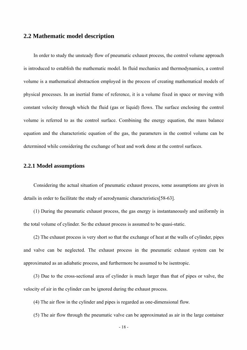
The classical circular piston source in an infinite rigid baffle has been investigated by many
authors[1]. The circular piston in an infinite rigid baffle, illustrated in Figure 3-1, is of interest
because it has relatively simple geometry; it serves conveniently as an introduction to the behavior
of all radiating surfaces; and it can be approximated by a speaker in a wall. The requirement that the
baffle be infinite means that edges are far enough removed for diffraction effects originating there
to be ignored. Alternatively, the edges of the baffle might be covered with a sound-absorbent
- 32 -
material with the same effect. Other authors have contributed about the classical circular piston
source as well. Shi[7] applied this piston sound source to estimate the intermittent exhaust noise
generated via a pneumatic value without silencers and have a reasonable prediction.
Figure 3-1 A piston source in an infinite baffle. The piston of radius a lies in the x - y plane and vibrates
vertically parallel to the z-axis with velocity amplitude U .
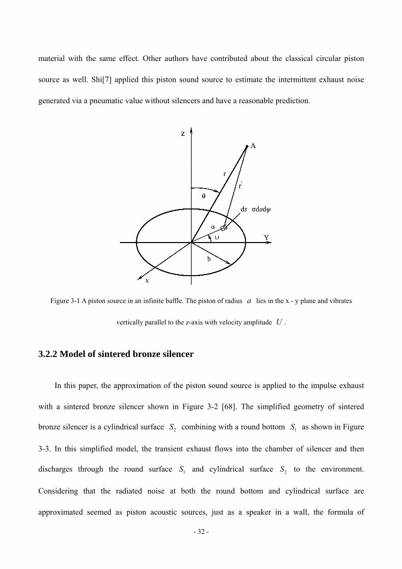
3.2.2 Model of sintered bronze silencer
In this paper, the approximation of the piston sound source is applied to the impulse exhaust
with a sintered bronze silencer shown in Figure 3-2 [68]. The simplified geometry of sintered
bronze silencer is a cylindrical surface 2S combining with a round bottom 1S as shown in Figure
3-3. In this simplified model, the transient exhaust flows into the chamber of silencer and then
discharges through the round surface 1S and cylindrical surface 2S to the environment.
Considering that the radiated noise at both the round bottom and cylindrical surface are
approximated seemed as piston acoustic sources, just as a speaker in a wall, the formula of

- 33 -
predicting SPL of the observation point A at a distance r from the outlet of ducts and at an
angle to the longitudinal axis will be derived in detail.
Figure 3-2 Photos of sintered bronze silencer.
Figure 3-3 Piston acoustic sources at the superficial surfaces of sintered bronze silencer. The circular
approximated piston S1 of radius b and cylindrical approximated piston S2 vibrate perpendicularly to the surfaces
with velocity amplitude U0.

- 34 -
Reference to Figure 3-2, the distance 1r of observation point A from the source B is given
by the following expression in terms of the centre-line distance r :
2 2 2 1/21 1( 2 cos 2 sin cos ) .r r H rH r (3-7)
For the case of far field where 2r b and 2r H , Equation (3-7) becomes
approximately:
1 1cos sin cos .r r H (3-8)
The distance 2r of observation point A from the source C at the cylindrical surface can
also be given as the similar expression of Equation (3-8) as:
2 2cos sin cos .r r h b (3-9)
The further simplification may be made while substituting Equation (3-8) and Equation (3-9)
into Equation (3-4) that the denominator is approximated sufficiently by the first term on the
right-hand side of the two distance equations. However, the last two terms must be retained in the
exponent, which reflects the fact that small variations in relative phase of the pressure contributions
arriving at the observation point have a very significant effect upon the sum [1,8,74].
3.2.3 Prediction of radiated exhaust noise
The hypothetical pistons in rigid baffles, generally restricted to a circle 1S of radius b and a
cylindrical surface 2S of radius b and height H , are assumed to vibrate with uniform normal
velocity j0
tU U e harmonically of amplitude 0U and angular frequency . The presence of
the baffles implies that all of the sound power radiated by the pistons is radiated into the
hemispherical half-space bounded by the planes of the baffles. Therefore the amplitudes of the

- 35 -
strength of the sources corresponding to the incremental areas 1 1d d dS and 2 2d d dS b h
are
m1 0 1 m2 0 22 d d , 2 d d ,Q U Q U b h (3-10)
respectively, of which the factor 2 is introduced to express that the noise radiates only
hemispherically due to the presence of the rigid pistons.
Considering contributions from all points over the piston surface, the total pressure at the
far-field observation point A radiated by the circular surface 1S is given as the following integral
expression:
12 j sin cosj( ) j cos0 0
m1 10 0
j( , , ) d d ,
2
b kt kr kHUp r t e e e
r
(3-11)
which can be derived to a simple expression by the Bessel function as:
2j( ) j cos0 0 1
m1
j J ( sin )( , , ) .
sint kr kHU b kb
p r t e er kb
(3-12)
The similar result of the total pressure at the far-field observation point A radiated by the
cylindrical surface 2S is of the form:
22 j sin cosj( ) j cos0 0
m2 20 0
2j( ) j cos0 0 0
j( , , ) d d
2
J ( sin )1
cos
H kbt kr kh
t kr kH
Up r t e be e h
r
U b kbe e
r kb
. (3-13)
The quantities 0J ( sin )kb and 1J ( sin )kb are Bessel functions of the first kind of order 0
and 1, respectively. Comparing Equation (3-12) and Equation (3-13), the difference of imaginary
unit 1/2j ( 1) represents that the directions of two piston surfaces are perpendicular to each other.
With the Fourier transform, SPL in frequency-domain at the far-field observation point A radiated
- 36 -
by the two piston surfaces can be calculated respectively, and read
220 0 1
Pm1 10r
22j cos0 0 0
Pm2 10r
( ) J ( sin )10log ,
sin
( ) J ( sin )10log 1 ,
coskH
U b kbL
rp kb
U b kbL e
rp kb
(3-14)
where r 20 μPap is the reference sound pressure in the air, 0 ( )U is the Fourier transform of
the amplitude of normal vibration velocity of the pistons that is the superficial velocity sv of the
transient exhaust flowing through the sintered bronze porous material.
For the noise radiated by the two equivalent quadrupoles mentioned above in Equation (3-6),
SPL Pq1L and Pq2L at the far-field observation point A will be calculated using the similar
expressions of Equation (3-14).
Therefore the prediction of total SPL containing the effects of monopoles and quadrupoles of
the two hypothetical piston surfaces can use the following formula:
Pq1 Pq2Pm1 Pm2/10 /10/10 /10
P 1010log (10 10 10 10 ) .L LL LL (3-15)

- 37 -
Chapter 4 Strategies of impulse exhaust noise suppression
In this chapter, the control strategies of impulse exhaust noise will be presented. There are
three approaches to control the noise from the sound source, the propagation path and the receiver,
respectively. Muffler devices are used to reduce the aerodynamic jet noise classically. The features
and disadvantages of various mufflers in the industrial applications will be introduced firstly. Unlike
the steady noise or period noise, the evaluations of impulse noise is introduced. Then a semi-active
control strategy to change the sound source of impulse exhaust by controlling the opening process
of exhaust valve is presented. The principle and specific control method will be introduced.
4.1 Classical control strategy
In order to suppress the exhaust noise, workers may wear the earplug in factories as the
earplug can weaken most of the high-frequency noise. However, wearing the earplug may affect the
hearing and conversation between peoples, so many workers do not like to use it. Mufflers as the
most frequently-used devices to control the aerodynamic noise, are commonly installed at the outlet
of exhaust systems by reflection or absorption of sound. There are several kinds of mufflers or
silencers. Expansion chamber mufflers as the simplest reactive muffler suddenly expand and reduce
the cross-section area to reflect the sound wave back to the source and reduce the amount of
acoustic energy transmitted. Unlike reactive mufflers, absorptive mufflers which incorporate sound
absorbing porous materials such as fiberglass, mineral wool and high-porosity foams to transform
acoustic energy into heat. Absorbing materials have some disadvantages including pollution, the
risk of high heat and limited lifetime therefore they may become ineffective and impractical.

- 38 -
Nevertheless, the porous mufflers are widely used in the pneumatic exhaust noise reduction because
of the desirable characteristics for broadband noise. Perforated panel with wide absorption sound
spectrum and high sound absorption coefficient was studied and applied to suppress the industrial
noise in recent decades. Muffling devices may suppress the generation of noise or attenuate noise
already generated passively on the noise propagation path; but they are designed for specific
equipment and might impede the exhaust, especially the dissipative mufflers. Alternatively, it can
become a serious source of noise if attention is not given to the design.
4.2 Semi-active control strategy
Although the mufflers are widely used in the industrial noise control, they are basically
designed according to the theories of reducing noise generated by the steady exhaust or period
exhaust. The impulse exhaust noise has a obvious unsteady characteristic due to the short impulse
exhaust, which is different from the steady noise or the period noise. It should pay close attention to
reduce not only the overall A-weighted SPL or the SPL in frequency but also the peak sound
pressure in time-domain.
4.2.1 Evaluations of impulse noise
The sensitivity of the human ear to sound (perceived sound) not only varies with the
magnitude (measured physically by a microphone) but also with the frequency. The apparent
loudness of a sound varies with frequency as well as with sound pressure. The variation of loudness
with frequency also depends to some extent on the sound pressure. The A weighted SPL is widely
used in assessing loss of hearing causing by the noise in industries due to its good approximation of
- 39 -
the ear response. There are several types of measurements to evaluate the impulse noise, such as
A-weighted equivalent level AeqL , the peak sound pressure [19].
The magnitude of the continuous signal like steady or fluctuating noise can be generally
expressed by an effective value which is based upon mean square value of signals. The quantity
AeqL is the equivalent continuous A-weighted noise level, which characterizes fluctuating noise as
an equivalent steady-state level and is defined as:
0
pA ( )/10
Aeq 100 0
110log 10 d dB(A)
TL tL t
T (4-1)
where 0T is a reference time and pA ( )L t is the A-weighted sound pressure level at time t .
However, the time-mean concept may not be applicable to an impulse noise because of its
short duration time. Thus it seems physically plausible that the total energy ( )E t of an impulse
signal ( )x t should be used for assessment of noise. As shown in Figure 4-1, the equivalent energy
can be given as a height of the square pulse 0( ) /e E t T . In order to make it physically more clear,
we can express a height of square pulse as a sound level pe (dB)L , defined as:
2
pe 100 00
1 ( )10log d
x tL t
T e
(4-2)
where 0e is a reference value (sound pressure of 5 2(2 10 Pa) ) and 0T is a reference time.
There are some different ways in determining 0T , but 0 1sT is generally accepted as a unit time.
In assessment of impulse noise, ISO (ISO 1996/1) also uses the same concept mentioned above.
This is illustrated in Figure 4-2. A sound exposure level ae (dB(A))L can be expressed similar to
Equation (4-2) as

- 40 -
2
1
2a
ae 10 20 0
( )110log d
t
t
p tL t
T p
(4-3)
where 0T is a reference time ( 0 1sT ), the interval between 1t and 2t indicating a duration time
of single impulse noise, a ( )p t and 0p are an A-weighted sound pressure and a reference sound
pressure ( 52 10 Pa ), respectively. The time 2 1t t t is defined as the duration time of impulse noise
required for the peak level to drop 20 dB.
Figure 4-1 Energy of impulse signal.
Figure 4-2 Sound exposure level of impulse signal.

- 41 -
If the noise data in time series are sampled at a time interval being sufficiently short compared
with the duration time of noise, then peL can be obtained by the following equation
p ( )/10
pe 1010
10 log 10n
L t
t
tL
T
(4-4)
where p ( )L t and n are the sound pressure value of each sample and the total number of sample, respectively.
It should be noted that, in this case, the sampling interval of data must be taken to be sufficiently
short compared with the averaging time. In this paper, the impulse exhaust noise is sampled in 50
kHz and the total time is 1 s as equal to the reference time 0T , according with the condition
mentioned above.
4.2.2 Principle
The impulse noise with high peak sound pressure is harmful to people and may cause hearing
damage. Thus, the suppression of peak sound pressure of impulse noise is the mainly purpose in this
section. It is known that the impulse exhaust noise is closely related of the transient exhaust flow,
and the peak sound pressure always occurs at the sonic exhaust stage, which is the very beginning
of the exhaust process because of the obvious pressure difference and suddenly huge amount air
flow. That is the focus stage requiring suppression at the time sonic choked exhaust happens.
Considering an impulse exhaust process of a fixed volume cylinder without silencer, the sound
pressure reaches the peak value when the mass flow rate is maximum as shown in Figure 4-3, the
measured cylinder pressure and sound noise signals during the impulse exhaust process. The mass
flow rate is calculated by Equation (2-7) and Equation (2-9). The figure also shows that the
envelope of noise signal is closed to the vary of mass flow rate at the throat of valve.

- 42 -
Figure 4-3 The cylinder pressure, noise and mass flow rate of impulse exhaust.
Focusing on the sonic exhaust stage, the pressure derivate can be obtained by Equation (2-4),
Equation (2-7) and Equation (2-9) as follows:
1 21/( 1) 31 2 3 1 2 *c v c0
c0 c cc
1 22 13
1 2 3 1 2 *c c0 a ac0 c c
c c c
d 22,
d 1 1
d 2,
d 1v
p S RTp p p p
t V
p S RT p pp p p p
t V p p
, (4-5)
where cp and cT are the pressure and temperature of air inside the cylinder, c0p and c0T are
initial values, cV is the cylinder volume, and vS is the effective cross-sectional area of the valve
throat, *p is the critical pressure ( /( 1)*a( 1) / 2p p
). Therefore, the pressure of cylinder is a
function of the valve throat area v ( )S t when the initial condition is fixed. In other words, the exhaust
process is according to the different opening process of valve.
In order to suppress the peak sound pressure of exhaust noise, the maximum of mass flow rate
should be limited. The total mass exhaust from the cylinder is almost same if the initial pressure

- 43 -
inside the cylinder is fixed because of the exhaust process is seemed as isentropic. Therefore, if the
mass flow rate keeps a steady value during the exhaust process, the form of mass flow rate is like a
square and the peak of impulse noise will be reduced maximally. According to Equation (2-4), the
mass flow rate can be derived as
c c
c
dd.
d d
V pm
t RT t (4-6)
Neglecting the temperature changes compared with the derivative of cylinder pressure, the
mass flow rate is approximatively proportional to the cylinder pressure derivative. Therefore, the
maximum of mass flow rate and the peak sound pressure of exhaust noise can be limited when the
cylinder pressure decreases linearly. The schematic diagram of principle is illustrated in Figure 4-4.
Figure 4-4 The schematic diagram of semi-active control strategy.
(a) The pressure curves of the ideal impulse exhaust and expected exhaust; (b) The pressure derivative curves of
the ideal impulse exhaust and the expected exhaust.
The ideal cylinder pressure during the impulse exhaust process is shown as the solid line if the
effective cross-sectional area of valve throat is constant. The impulse exhaust starts from time 0t ,
before which the pressure of cylinder keeps the initial value 0p . The cylinder pressure decreases

- 44 -
rapidly in the sonic exhaust stage from the initial pressure 0p to the critical pressure *p at time
1t , and softly in the subsonic exhaust until the ambient pressure at time 2t . The derivative of
pressure suddenly steps to the peak value at the beginning of exhaust, then decreases gradually
during the sonic exhaust stage as the power function presented in Equation (4-5). This also proves
the transient peak value of impulse noise reaches at the initial stage. After that, the derivative of
pressure continues to decrease but according to a more complex raw as Equation (4-5) for the
subsonic exhaust process. If the cylinder pressure decreases linearly as the dash line, the pressure
derivative will be a constant. Furthermore, the mass flow rate approximately being proportional to
the pressure derivative in the sonic exhaust stage will be limited to minimum so that the flow noise
due to the unsteady mass flow can be reduced and the peak of sound pressure may keep stable.
4.2.3 Control method
The principle of semi-active control strategy for suppressing the impulse exhaust noise is to
linearize the cylinder pressure by controlling the opening process of valve. When the initial state
parameters of air inside the cylinder are known and the expected exhaust time t is chosen, the
linearized pressure during the exhaust process can be obtained by the following expression as:
0 a0 0( ) ( ) .
p pp t p t t
t
(4-7)
In accordance with Equation (4-5), the effective cross-sectional area of valve throat can be
given as a variable to ensure the cylinder pressure decreasing as expected. Here we should also
consider the saturation value of area due to the structure of valve.

- 45 -
Chapter 5 Experimental study
In this chapter, experimental study will be presented. The experiments were based on a
pneumatic friction clutch and brake (PFC/B) system of mechanical press and also a simplified
cylinder exhaust system. In order to test the presented semi-active noise control strategy, a modified
pneumatic valve was designed, which can adjust the poppet valve by a servo motor. The
experimental results will be shown to verify the validity of the presented aerodynamic model and
the radiated noise predictions. The noise were analyzed to study the effect of presented suppression
strategy comparing to the direct exhaust.
5.1 Experimental apparatus
5.1.1 PFC/B test-bed
The experiment was based on a PFC/B system of JH23-63 mechanical press as shown in
Figure 5-1. Without silencer and with a sintered bronze silencer installed at the outlet of valve, the
cylinder pressure and the exhaust noise were measured by a pressure sensor and a microphone with
sound level meter. The real exhaust system was set in a large room ( 7 × 7 × 6 m ) including an
acting cylinder, a hybrid regulator valve VY1700, exhaust pipes, a sintered bronze silencer MS010A
as shown in Figure 3-2, a pressure sensor GB-3000A, a sound level meter Type 2270 with
microphone 4189, etc. The microphone was fixed at a distance of 1 m from the silencer and at an
angle of 45° to the longitudinal axes of the exhaust outlet. The sensitivity of sound level meter is
47.57 mV/Pa. Both the cylinder pressure and exhaust noise signals were recorded by a 12 bit A/D
converter multifunction card PCI-1712 with 200 kHz sampling rate. In addition, the experiments

- 46 -
were tested in night with the background noise less than 30 dB for ignoring the influence of
environmental disturbance.
Figure 5-1 Pneumatic exhaust system based on a PFC/B system of JH23-63 mechanical press.
5.1.2 Modified pneumatic valve
In order to test and verify the semi-active noise control strategy presented in Chapter 4, a
3/2-way directional valve was modified, of which the schematic diagram is shown in Figure 5-2.
The modified pneumatic valve is composed of a servo motor, a ball-screw pair, poppet valves, a
valve body and covers. When the poppet valve moves downward to the position as shown in Figure
5-2, the air from port P is supplied into port A. Conversely, when the poppet valve moves upward,
the passage between port P and port A is closed, but allowing the air to be discharged from port A to
port R. Different from the ordinary pneumatic directional valve driven by a pilot solenoid valve, the
modified valve is driven by a servo motor. The rotation of motor is converted into linear movement
of poppet valve by the ball-screw unit. This is a kind of half-open-loop control system. Thus, the
poppet valve can be adjusted accurately by the position control of servo motor. The displacement of

- 47 -
poppet valve is obtained by the integral of the encoder pulse signals.
Figure 5-2 Modified pneumatic valve. It includes 1-bearing; 2-ball-screw pair; 3-poppet valve; 4-poppet valve;
5-body; 6-cover; 7-feed back passage; 8-cover; 9-servo motor.
5.1.3 Simplified cylinder exhaust test-bed
The simplified cylinder exhaust test-bed was based on a simple pneumatic system composed of
an air compressor, an air treatment device including filter, relief valve and lubricator (FRL), a
3/2-way directional valve and a cylinder as shown in Figure 5-3. The system was set in a large room
in order to simulate the real environment in an application. A pressure sensor GB-3000A was
installed at the duct near the cylinder to measure the cylinder pressure. A microphone 4189
connected with a sound level meter Type 2270 was placed at a distance of 1 m and at an angle of
45° to the longitudinal axes of the valve outlet to measure and record the impulse exhaust noise.

- 48 -
The valve position was obtained by the counting of motor encoder signals. All of the experimental
data were recorded by a high-speed A/D converter multifunction card PCI-1712 with 50 kHz
sampling rate. Additionally, the background sound was 30 dB much lower than the exhaust noise
when the experiments were carried out at night.
Figure 5-3 Simplified exhaust system. The volume of cylinder is fixed.
5.2 Results of aerodynamic model
The experiments were carried out based on the introduced PFC/B test-bed to verify the
aerodynamic models of impulse exhaust process and porous material with rigid frame presented in
Chapter 2. Experiments measured the cylinder pressures of the exhaust system which exhausted
directly and with a sintered bronze silencer, respectively. The exhaust processes under some
different initial cylinder pressure conditions were tested, of which the results are presented and
discussed in details.

- 49 -
5.2.1 Direct exhaust without silencer
According to the aerodynamic model of direct exhaust by PFC/B exhaust system, the initial
value problem for ODE as equation (2-17) can be solved by using the ode functions of Matlab (e.g.
ode45). Thus, the parameters of the direct exhaust process are obtained. Figure 5-4 shows the
cylinder pressures with different initial conditions, that the initial pressures in the cylinder are 0.36
MPa and 0.48 MPa, respectively. The pressure reduces to the ambient pressure ( ap 0.0968 MPa)
in a very short time, less than 0.13 s. At the beginning of exhaust, the cylinder pressure derivative
increases gradually due to the change of effective cross-sectional area of the valve VY1700. When
the cylinder pressure decreases at about 0.15 MPa, the speed of pressure drop increases because the
piston begins to move to reduce the volume of cylinder. The errors of calculated cylinder pressure
compared to the experimental results are about 4.6 percent for the maximum value and less than 1.6
percent for the mean absolute value. That verifies the applicability of the presented aerodynamic
model of impulse exhaust through pneumatic valve.
Figure 5-4 Cylinder pressure of direct exhaust process.

- 50 -
In order to analyze the aerodynamic properties of impulse exhaust, some difficulty measured
parameters can also calculated by the mathematic model of direct exhaust, such as mass flow rate
and mach number at the throat of valve. Figures 5-5 and 5-6 show the calculated results of mass
flow rate and mach number at the valve throat under different initial pressures 0.36 MPa and 0.48
MPa. Because of the opening response of valve, the mass flow rate shown in Figure 5-5 increases
when the exhaust starts, although the mach number at the valve throat shown in Figure 5-6 reaches
1 at the same time. The higher initial pressure of cylinder means that there are more air will exhaust
through the valve. Therefore, the total quality of exhaust air, as the integral of mass flow rate curve,
will be larger and the exhaust will takes longer time when the air inside the cylinder has a higher
initial pressure. Comparing Figures 5-4 and 5-6, when the cylinder pressure is larger than the
critical value a1.8929 p , the sonic choked exhaust happens and the mach number at the valve throat
equals to 1. In addition, it can be seen clearly from Figure 5-6 that the higher initial pressure will
extend not only the total exhaust but also the sonic choked exhaust process.
Figure 5-5 Mass flow rate at the valve throat of direct exhaust process.

- 51 -
Figure 5-6 Mach number at the valve throat of direct exhaust process.
5.2.2 Exhaust with sintered bronze silencer
According to the simplified aerodynamic model of pneumatic system with sintered bronze
silencer established above, the parameters of the exhaust process are also calculated by using the
ode functions in Matlab. Figure 5-7 shows the comparison of the measured and calculated pressure
of the pneumatic cylinder with different initial pressures: 0.36 MPa and 0.48 MPa. The pressure
reduces to the ambient pressure in a short time, which is little longer than that of direct exhaust
process. The calculated results with the maximum error of about 4.4 percent and the mean absolute
error less than 2 percent confirm to the actual exhaust process at different initial conditions, which
verifies the applicability of the presented aerodynamic models of impulse exhaust and porous
material with rigid frame.
As same as the analysis of direct exhaust, the mass flow rate through the sintered bronze
silencer is also calculated by the aerodynamic model with the Ergun equation, as shown in Figure
5-8. The mass flow rate increases rapidly in the early stage and gets the peak, the time taken for

- 52 -
which is about 28 ms which is independent of the initial cylinder pressure. Then it reduces until the
end of the exhaust process since the cylinder pressure decreases. Nevertheless, the integral of the
mass flow rate represents the total quality of exhaust air from the pneumatic cylinder, and is related
to the initial cylinder pressure obviously.
Figure 5-7 Cylinder pressure of exhaust process with sintered bronze silencer.
Figure 5-8 Mass flow rate at the valve throat of exhaust process with sintered bronze silencer.

- 53 -
It can be seen from the above discussions, the presented aerodynamic model can used to
analyze the flow properties of the impulse exhaust and also of the porous material with rigid frame.
The results are reasonable so that according to the mathematic model, we can have a more in-depth
understanding of the impulse exhaust process.
5.3 Results of radiated noise prediction
Based on the previous discussions, the primary monopole and quadrupole sources of transient
exhaust noise can be related to the mass flow rate and other parameters. The flow parameters can be
calculated by the aerodynamic model. Therefore, the sound pressure of the radiated acoustic field at
far field (1 m in the experiments) can be predicted. The noise signals generated by the impulse
exhaust of PFC/B exhaust system with a sintered bronze silencer were recorded and analyzed to
verify the applicability of presented prediction theory of radiated noise.
5.3.1 Noise prediction in time-domain
Figure 5-9 shows the relationship between the acquired noise signal and the calculated sound
pressure related to the flow parameters through the sintered bronze silencer in time-domain. In
order to compare conveniently, the noise signals are shifted 2.94 ms forward to counteract the sound
propagation time. It is shown that the predicted results are similar with the upper envelope of the
noise signal at different initial pressures. Both the magnitude and the peak time of calculated sound
pressure are matched well. Therefore, the flow parameters can be used to predict the sound pressure
and reflect the magnitude information of the impulse exhaust noise to a certain degree.

- 54 -
Figure 5-9 Prediction of the radiated exhaust noise in time-domain.
The initial pressures are, respectively, (a) 0.36 MPa, (b) 0.40 MPa and (c) 0.48 MPa.
5.3.2 Noise spectrum prediction
According to the approximation of piston acoustic source, the SPL is calculated and compared
with the measured results at the initial cylinder pressures of 0.40 MPa and 0.48 MPa, as shown in
Figures 5-10 and 5-11. Due to the effect of the equivalent factor 2 2e2k d of quadrupoles, the
monopole sources play a major role in contributing to the low-frequency of sound pressure, whereas
the quadrupoles primarily contribute to the high-frequency. The predicted SPL accords with the
experiments well, even though the details are not exactly identical, especially at the low-frequency.
This can be explained by the filtering effect of the Bessel function. On the other hand, the reason is
also that the far-field condition becomes not suitable for the calculation model of sound radiation
with longer wavelength. Nevertheless, the mean absolute error of octave band SPL is less than 1.5

- 55 -
dB, and the maximum difference is only 2.7 dB at the center frequency 8 kHz as shown in Figure
5-11. Therefore, the presented SPL prediction of transient exhaust through the sintered bronze
silencer in frequency-domain is reasonable.
Figure 5-10 SPL prediction of the radiated exhaust noise.
The initial pressures are, respectively, (a) 0.40 MPa and (c) 0.48 MPa.
Figure 5-11 Octave band SPL prediction of the radiated exhaust noise.
The initial pressures are, respectively, (a) 0.40 MPa and (c) 0.48 MPa.
- 56 -
The above discussions show that the radiated exhaust noise can be predicted both in the
time-domain and frequency-domain by using the presented mathematic models. The impulse
fluctuation of exhaust noise is related to the transient mass flow. The piston acoustic source
approximation can be used to analyze the SPL spectrum at a far-field observation point. Such
researches will provide references for the study of impulse exhaust and its radiated noise and also
for the study of suppression strategies.
5.4 Results of impulse exhaust noise suppression
Because the amplitude of impulse exhaust noise is related to the mass flow rate at the outlet of
exhaust system as the previous discussions, the noise is suppressed by smooth the mass flow rate
according to the semi-active control strategy by controlling the opening process of pneumatic valve.
The verify experiments were carried out based on the introduced simplified cylinder exhaust
test-bed with a modified 3/2-way directional valve. Then the results of such strategy will be
presented in details.
5.4.1 Exhaust with normal solenoid valve
Firstly, the results of exhaust with an normal solenoid valve are presented as references. The
structure of solenoid valve is same as the modified valve shown in Figure 5-2, but driven by a pilot
solenoid valve. The valve can complete the reversing operation in a very short time due to the small
displacement of poppet valve. However, since the intake and exhaust of pilot valve take a time, the
response of switch is about 50 ms. Figure 5-12 shows experimental results of the cylinder pressure
and its derivative with different initial pressures 0.33 MPa, 0.38 MPa and 0.44 MPa. The valve was

- 57 -
opened to discharge the cylinder air at the time 0.2 s in every exhaust process for synchronism. As
previously mentioned, the pressure decreases as an approximate power function after the delay time
of the valve response. The curves are smoother than that of exhaust in PFC/B system due to the
fixed cylinder volume. The pressure derivative reaches the maximum value at the very beginning of
the exhaust process, and then decreases gradually. The total exhaust times are about 500 ms, 540 ms
and 570 ms, respectively, if considering the response time. Additionally, the higher initial pressure
means there are more gases and more potential energy inside the cylinder. Thus, it will generate
much more impact and takes a longer time.
Figure 5-13 shows the results of the recorded noise signals and the calculated mass flow rate of
valve throat. There are some small noise signals appearing before the noises reaching to the peak
value, which represents the noise generated by the exhaust of pilot solenoid valve. The peak SPL
are 136.7 dB(A), 137.8 dB(A) and 139.2 dB(A), respectively, as references.
Figure 5-12 The cylinder pressure and its derivative of exhaust with an original solenoid valve.

- 58 -
Figure 5-13 The noise signals and mass flow rate at the valve throat of exhaust with an original solenoid valve.
5.4.2 Exhaust with modified valve
In accordance with the strategy of noise suppression, the expected exhaust time are setting as
300 ms, 400 ms and 500 ms, which are identified by slow, medium and fast. The expected pressure
can be solved by Equation (4-7) and then the effective cross-sectional area of valve can be obtained
by Equation (4-5). Controlling the servo motor rotates according to the designed speed, the poppet
valve of modified pneumatic valve will be moved as an expected specific curve as shown in Figure

- 59 -
5-14. The area changing curves in Figure 5-14 were according to the expected movements with
initial pressure 0.44 MPa and recorded by the encoder signals. Such curves in Figure 5-14 show that
the poppet valve was controlled to open a small area at 0.2 s suddenly, and then was droved to
increase the area nonlinearly until to the limit position. The area has a maximum value
4 25.25 10 m because of the structure limit of valve. The area changing of exhaust with other two
initial pressures 0.33 MPa and 0.38 MPa are similar, but have some minor differences such as the
step area values at the beginning.
Figure 5-14 The effective cross-sectional area of valve according to the different expected exhaust time.
Under control of the opening process of valve according to the designed curves, the exhaust
process will carry out in accordance with the expectations. The cylinder pressure curves of exhaust
with different designed area changing are shown in Figure 5-15. The initial cylinder pressures are
0.33 MPa, 0.38 MPa and 0.44 MPa, respectively. It can be seen that the pressure changes are
significantly different from that controlled by a solenoid valve as shown in Figure 5-12. The
pressure decreases as an approximate straight line drawn by dash curves, of which the gradient is

- 60 -
related to the initial pressure and the expected exhaust time. In addition, the delay is shorter than
that in the exhaust controlled by a solenoid valve due to the rapid response of motor rather than the
pilot valve. The pressure decreases nonlinearly in the later exhaust process, because of the limit of
effective cross-sectional area of valve and the complex phenomenon during the subsonic exhaust.
Figure 5-15 The cylinder pressures according to the fast medium and slow opening process of valve with different
initial pressures, (a) 0.33 MPa; (b) 0.38 MPa; (c) 0.44 MPa.

- 61 -
Figure 5-16 shows the suppressed impulse exhaust noise based on the three groups of valve
opening processes and the calculated mass flow rate of the flow through valve. The envelope of
such noise signals are very different from the noise generated by the exhaust with a solenoid valve.
There are no small noises at the beginning, which exist in the solenoid valve exhaust causing by the
pilot valve exhaust. The noise signals reach the peak values and stay for a certain time
approximately, as the same as the expected effect. Apparently, the slower opening process of valve
extends the exhaust process, thus the energy of noise is dispersed. Compared to the exhaust with a
solenoid valve, the peak SPL of exhaust with the presented control strategy is reduced obviously.
Figure 5-16 The noise signals and mass flow rate at the valve throat of exhaust according to the fast medium and
slow opening process of valve with different initial pressures, (a) 0.33 MPa; (b) 0.38 MPa; (c) 0.44 MPa.

- 62 -
5.4.3 Discussions of noise suppression
The above experimental results show intuitively that both the pressure and exhaust noise were
changed significantly due to the semi-active noise control strategy by controlling the valve opening
process. The pressure decreasing linearly means the mass flow rate is relatively stable especially
during the sonic exhaust stage, reflected by the stable peak value of noise. Then some discussions
are presented to checkout the effect of the semi-active noise control strategy by comparing the
parameters and the noise criterions of the experimental results.
1) Exhaust extended ratio
Exhaust extended ratio is the ratio of the extended exhaust time and the exhaust time with
normal solenoid valve. It is used to evaluate the aerodynamic performance of the impulse exhaust,
which is shown in Figure 5-17. It can be seen that the extended ratio almost between 20 percents to
55 percents increases if the longer expected exhaust time is chosen. In fact, the exhaust extended
time is almost same when the cylinder air discharges with different initial pressures, but the ratio is
smaller while there is higher pressure air in the cylinder before exhaust.
2) Noise reduction of peak SPL
The noise reduction of peak SPL is one of the most concerned criterions of the impulse exhaust
noise suppression. Figure 5-18 shows the results of the noise reductions of peak SPL. The
maximum noise reductions of peak SPL are 9.4 dB(A), 8.3 dB(A) and 4.7 dB(A), respectively, with
different initial cylinder pressures when the valve is opened as the slow curves. By the strategy of
noise control, the peak SPL is reduced at least about 2 dB(A), which means the sound energy at the
peak is suppressed about 36 percents. In addition, it can be seen that there is a better effect of
suppression in the low-pressure gas discharging.

- 63 -
Figure 5-17 Exhaust extended ratio.
Figure 5-18 Noise reduction of peak SPL.
3) Sound exposure level
Comparing the sound exposure level shown in Figure 5-19, as defined by Equation (4-3) or
(4-4), the results are similar with the peak SPL reduction. With the semi-active control strategy, the
sound exposure level is reduced. The exposure energy of impulse noise is suppressed at least 7
percents when the initial pressure is 0.44 MPa and the exhaust controlled with the fast open curve of
the valve area.

- 64 -
4) Duration time of impulse noise
The presented strategy is to limit the peak SPL of impulse exhaust noise by smoothing the
amplitude of noise. Thus, the duration time of impulse noise will be extended as shown in Figure
5-20. The most longer duration time in this study is about 2.5 times than that of reference exhaust.
From the point of view that the noise threshold increases 3 dB if the exposure time decreases by
half, the presented strategy has an acceptable effect on the suppression of impulse exhaust noise.
Figure 5-19 Sound exposure level.
Figure 5-20 Duration time of impulse noise.

- 65 -
5) Octave band SPL
Additionally, the spectral characteristics of impulse exhaust noises with and without
controlling are shown in Figure 5-21. It can be seen from the octave spectrum that the control
strategy has a significant suppression of impulse exhaust noise (about 10 to 20 dB reduction) in the
frequencies below 250 Hz, where the noise source is mainly caused by the shock of mass flow. In
the high-frequency, the strategy of changing the valve opening process is not obvious but still has a
small effect in the attenuation.
Figure 5-21 Octave band SPL of noise generated by the impulse exhaust.
Overall, during the impulse exhaust process with same initial cylinder pressure or same initial
potential energy, the energy is released and converted to kinetic energy in a short time. The impulse

- 66 -
exhaust noise is essentially generated in such an energy conversion process. Extending the exhaust
disperses the impulse noise in the time-domain, so that the noise is diffused to a longer period of
time and the peak valve is reduced. The presented strategy of controlling the valve opening process
makes the reduction effect of the noise peak maximally, since the peak can be controlled at a stable
value especially during the sonic exhaust stage. In the experiments, the suppressed impulse exhaust
noises became to sound much quieter and acceptable. On the other hand, performance may be
affected if the exhaust lasts too long especially in some pneumatic systems with special
requirements. In the practical applications the common used silencers such as porous diffusion
silencers also have this problem, that the exhaust extended rate may reach to 40% due to the
resistance of sound absorption material especially when the amount of exhaust air is large.
Nevertheless, some appropriate additional exhaust time is also accepted as long as the systems can
work normally.
- 67 -
Chapter 6 Conclusions and future work
6.1 Main conclusions
As presented in previous chapters, characteristic analysis and suppression strategy of impulse
exhaust noise have been investigated both theoretically and experimentally. The study was based on
the impulse exhaust of pneumatic systems and paid attention to both the aerodynamic properties and
the flow noise characteristics. Considering the relation between the exhaust flow and the radiated
noise, a strategy of noise suppression was presented and verified by experiments. In this chapter, a
brief summary of the whole research and major conclusions obtained in the study are given.
1. The aerodynamic properties of impulse exhaust based on typical pneumatic exhaust
systems have been investigated. A simplified aerodynamic model with a dynamic
equation of piston is derived from thermodynamics and presented to analyze the
exhaust process. The aerodynamic model of porous material with rigid frame such as
sintered bronze was established from the pressure drop described by the Ergun
equation. According to the aerodynamic models, the flow parameters during the
impulse exhaust were obtained and verified by experiments.
2. The sound sources of impulse exhaust noise were studied based on the Lighthill's
general theory of aerodynamic noise. This mass flow rate is related to the monopole
source of impulsive exhaust noise. With piston acoustic source approximation of
sintered bronze silencer, the sound pressure of radiated noise at far field observation
point have been predicted by the flow parameters calculated from the simplified
aerodynamic model.

- 68 -
3. A semi-active noise control strategy have been presented to suppress the impulse
exhaust noise especially to reduce the peak SPL. The principle was introduced that is
to smooth the impulse noise by the linearization of cylinder pressure decreasing and
the mass flow rate at the valve throat. Experiments show that the strategy can reduced
both the peak SPL and sound exposure level obviously.
6.2 Future work
Although some work have been done on the aerodynamic properties of impulse exhaust, the
sound sources and radiated noise characteristics of impulse noise, the investigation of noise
suppression, much further work is required to investigate the mechanism and to improve the
reduction of impulse exhaust noise in industry. The future work can be focused on the following
aspects.
1. The aerodynamic model presented in this work is simplified based on the control
volume, which ignores the complex structure of the real pneumatic system. The
computational fluid dynamics (CFD) could be used to simulate the detailed impulse
flow and also to predict the radiated noise by aerodynamic noise theories.
2. The introduced noise control strategy was verified by a modified valve with servo
motor. In the future, a valve with simple structure to achieve the effective area control
could be studied. Furthermore, combining the presented strategy with classical
silencers could be investigated to improve the suppression effect.
- 69 -
References
1. David A. Bies and Colin H. Hansen, Engineering Noise Control-Theory and practice[M], Second edition, E &
FN Spon, London, 1997.
2. H. D. Baumann and W. B. Coney, "Noise of gas flows", Chap. 15 in Noise and Vibration Control
Engineering-Principles and Applications[M], Second edition, edited by Istvan L. Ver and Leo L. Beranek,
Wiley, New York, 2006.
3. D. M. Jang, Gas Flow in Internal Combustion Engine[M], Beijing: China Machine Press, 1985. (in Chinese)
4. Miller GT. Living in the Environment-principles, connections and solutions[M]. Belmont: Brooks/Cole
Publishing Company, 2000.
5. Miller GT. Environmental Science-Working with the Earth[M]. Belmont: Brooks/Cole Publishing Company,
2001.
6. D.Y. Maa, P.Z. Li, G.H. Dai, H.Y. Wang, Shock associated noise from choked jets[J], Acta Acustica, 3 (1980)
172-182. (in Chinese)
7. H.S. Shi, S.D. Zhao, Prediction of radiation characteristic of intermittent exhaust noise generated via
pneumatic value[J], Noise Control Engineering Journal, 57 (2009) 157-168.
8. J. X. Li, S. D. Zhao and K. Ishihara, Study on acoustical properties of sintered bronze porous material for
transient exhaust noise of pneumatic system[J], J Sound Vibr., 332(11), (2013),2721-2734.
9. S.D. Zhao, J. Wang, J. Wang, Y. He, Expansion-chamber muffler for impulse noise of pneumatic frictional
clutch and brake in mechanical presses[J], Applied Acoustics, 67 (2006) 580-594.
10. J.A. Daggerhart, E. Berger, An evaluation of mufflers to reduce punch press air exhaust noise[J], Noise Control
Engineering, 4 (1975) 120-123.
11. S. Sahlin, Origins of punch press and air nozzle noise[J], Noise Control Engineering, 3 (1974) 4-9.
12. J. X. Li, K. Ishihara and S. D. Zhao, Experimental study on performance of various mufflers for intermittent
exhaust noise reduction[C], Inter-Noise2011, (2011).
13. S. Zimmermann and R. Ellis. Engineering Acoustics: An Introduction to Noise Control[M], Second Edition.
London, UK, Springer, 2009.
14. Rosenblith, W. A. and Stevens, K. N. Noise and man.. Handbook of Acoustic Noise Control[M] , WADC
TR52-204, Vol. 2. 1953
15. Dejong, R. G. and Groeneveld, Y. CEC joint project on impulse noise: Overall results of the field survey[C]. In
Proc . of Inter-Noise. (1985), 905-908.
16. Flindell, I. H. and Rice, C. G. CEC joint project on annoyance due to impulse noise: Laboratory studies. ISVR
Memo 677, (1986), 1984-1985.
17. International Organisation for Standardization Draft Addendum ISO 3891/DAD 1, Acoustics, (1981).
18. IEC-Pub. 179A Precision sound level meters additional characteristics for the measurement of impulsive
sounds, (1973).
19. S. Raghunathan, H. D. Kim and T. Setoguchi, Impulse noise and its control[J], Prog. Aerospace Sci., 34,
(1998)
20. Morata TC, Themann CL, Randolph RF, et al. Working in noise with a hearing loss perceptions from
workers,supervisors,and hearing conservation program managers[J]. Ear Hear, 2005, 26 (6): 529-545.
21. M.J. Lighthill, On sound generated aerodynamically: Part 1[J]. General theory, Proceedings of the Royal

- 70 -
Society of London A, 211 (1952) 564-587.
22. M.J. Lighthill, On sound generated aerodynamically: Part 2[J]. Turbulence as a source of sound, Proceedings
of the Royal Society of London A, 214 (1954) 1-32.
23. Lighthill MJ. The Bakerian Lecture, 1961. Sound Generated Aerodynamically[J]. Proceedings of the Royal
Society of London Series A, Mathematical and Physical Sciences, 1962, 267 (1329): 147-182.
24. Kobrynski M. General Method for Calculating the Sound Pressure Field Emitted by Stationary and Moving
Jets[J]. AFOSR-UTIAS Symposium on Aerodynamic Noise,Toronto, 1968: 112-130.
25. Goldstein M, E. Aeroacoustics[M]. McGraw: Hill Book Company, 1964.
26. Ribner HS. The Generation of Sound by Turbulent Jets-Advances in Applied Mechanics[M]: Academis Press,
1964.
27. Doak PE. A Critical Review of Conceptional Adequacy and Physical Scope of Existing Theories of
Aerodynamic Noise[J]. Journal of Sound and Vibration, 1972, 25: 263-335.
28. Dowling AP, Ffowcs Williams JE, Goldstein ME. Sound Production in a Moving Stream[J]. Phil Trans, roy,
Soc(London), 1978, 288: 321-349.
29. Ffowcs Williams JE. Jet Noise at very Low and very High Speed[J]. AFOSR-UTIAS Symposium on
Aerodynamic Noise,Toronto, 1968: 131-146.
30. Powell A. On the Mechanics of Choked Jet Noise[J]. ProcPhysSoc, 1953, 66: 313-327.
31. S. Ergun, A.A. Orning, Fluid flow through packed columns[J], Chemical Engineering Progress, 48 (1952)
89-94.
32. I.F. Macdonald, M.S. El-Sayed, K. Mow, F.A.L. Dullien, Flow through porous media-the Ergun equation
revisited[J], Industrial & Engineering Chemistry Fundamentals, 18 (1979) 199-208.
33. J.L. Lage, B.V. Antohe, Darcy's experiments and the deviation to nonlinear flow regime[J], Journal of Fluids
Engineering, 122 (2000) 619-625.
34. N. Robert K, Physical insight into the Ergun and Wen & Yu equations for fluid flow in packed and fluidised
beds[J], Chemical Engineering Science, 57 (2002) 527-534.
35. M. Mayerhofer, J. Govaerts, N. Parmentier, H. Jeanmart, L. Helsen, Experimental investigation of pressure
drop in packed beds of irregular shaped wood particles[J], Powder Technology, 205 (2011) 30-35.
36. J.-F. Allard, N. Atalla, Propagation of sound in porous media: modeling sound absorbing materials[M], Second
edition, Wiley, New York, 2009.
37. D.L. Johnson, J. Koplik, R. Dashen, Theory of dynamic permeability and tortuosity in fluid-saturated porous
media[J], Journal of Fluid Mechanics, 176 (1987) 379-402.
38. S.R. Pride, F.D. Morgan, A.F. Gangi, Drag forces of porous-medium acoustics [J], Physical Review B, 47
(1993) 4964-4978.
39. Y. Champoux, J.-F. Allard, Dynamic tortuosity and bulk modulus in air-saturated porous media[J], Journal of
Applied Physics, 70 (1991) 1975.
40. D. Lafarge, Dynamic compressibility of air in porous structures at audible frequencies[J], The Journal of the
Acoustical Society of America, 102 (1997) 1995-2006.
41. M. Fringuellino, C. Guglielmone, Progressive Impedance Method for the classical analysis of acoustic
transmission loss in multilayered walls[J]. Applied Acoustics, 59 (2000) 275-285.
42. A.K. Vashishth, P. Khurana, Waves in stratified anisotropic poroelastic media: a transfer matrix approach[J],
Journal of Sound and Vibration, 277 (2004) 239-275.
43. C.M. Lee, Y. Xu, A modified transfer matrix method for prediction of transmission loss of multilayer acoustic
materials[J], Journal of Sound and Vibration, 326 (2009) 290-301.
44. A. Hocine, B. Desmet and S. Guenoun, Numerical study of the influence of diesel post injection and exhaust
gas expansion on the thermal cycle of an automobile engine[J], Appl. Them. Eng., 30, (2010) 1889-1895.

- 71 -
45. S. D. Morris, Choked gas flow through pipeline restrictions: an explicit formula for the inlet Mach number[J],
Journal of Hazardous Materials, 50, 71-77, (1996).
46. F. Payri, A. Broatch, J.M. Salavert, D. Moreno, Acoustic response of fibrous absorbent materials to impulsive
transient excitations[J], Journal of Sound and Vibration, 329 (2010) 880-892.
47. Bugaru M, Vasile O. Transfer matrix method for a single-chamber mufflers[J]. Proceedings of the 11th
WSEAS International Conference on Applied Mathematics (MATH '07), 2007: 47-50.
48. Munjal ML. Velocity ratio-cum-transfer matrix method for the evaluation of a muffler with mean flow[J].
Journal of Sound and Vibration, 1975, 39: 105-119.
49. Munjal ML. acoustics of Ducts and Mufflers-With Application to Exhaust and Ventilation System Design[M].
Canada: John Wiley & Sons,Inc., 1987.
50. Cuesta M, Cobo P. Active control of the exhaust noise radiated by an enclosed generator[J]. Applied Acoustics,
2000, 61 (1): 83-94.
51. Cuesta M, Cobo P. Optimisation of an active control system to reduce the exhaust noise radiated by a small
generator[J]. Applied Acoustics, 2001, 62 (5): 513-526.
52. Sathyanarayana Y, Munjal ML. A hybrid approach for aeroacoustic analysis of the engine exhaust system[J].
Applied Acoustics, 2000, 60 (4): 425-450.
53. Torregrosa AJ, Broatch A, Fernandez T, et al. Description and measurement of the acoustic characteristics of
two-tailpipe mufflers[J]. Journal of the Acoustical Society of America, 2006, 119 (2): 723-728.
54. Ikeda T, Nishimura T, Ando T, et al. Resonance of elliptical perforated tube muffler[J]. Electronics and
Communications in Japan Part Iii-Fundamental Electronic Science, 2000, 83 (8): 51-60.
55. Broatch A, Serrano JR, Arnau FJ, et al. Time-domain computation of muffler frequency response: Comparison
of different numerical schemes[J]. Journal of Sound and Vibration, 2007, 305 (1-2): 333-347.
56. Sinder DJ. Speech Synthesis Using An Aeroacoustic Fricative Model[D]. New Brunswick Rutgers: The State
of University of New Jersey, 1999.
57. E-P HYREG, Series VY1700. 14-10. www.smc.com
58. Zhao SD, Shang CY, Zhao ZG, et al. Radiation Characteristics of Intermittence Exhaust Noise[J]. Chinese
Journal of Acoustics, 2000, 19 (4): 309-316.
59. Kinsler LE, Austin R. Frey, Alan B. Coppens, et al. Fundamentals of Acoustics[M]. New York: John Wiley &
Sons, Inc., 2000.
60. Jeyapalan RK, Halliwell NA. Machinery Noise Predictions at the Design Stage Using Acoustic Modeling[J].
Applied Acoustics, 1981, 14 (5): 361-376.
61. Rabiner LR, Schafer RW. Digital Processing of Speech Signals[M]. New York: Prentice Hall, Inc., Englewood
Cliffs, N. J. , 1978.
62. Webster AG. Acoustical Impedance, and the Theory of Horns and of Phonograph[J]. Proceedings of the
National Academy of Sciences, 1919, 5 (7): 275-282.
63. Shi HS, Zhao SD. Pre-Reducing the Intermittent Exhaust Noise by Optimizing the Exhaust Pipeline at the
Design Stage[J]. Imece 2008: Proceedings of the Asme International Mechanical Engineering Congress and
Exposition, Vol 5, 2009: 61-66.
64. Shi HS, Zhao SD, Wen JP. An Improved Particle Swarm Optimization for Pre-denoise at the Exhaust Pipeline
Design Stage[J]. Ieem: 2008 International Conference on Industrial Engineering and Engineering Management,
Vols 1-3, 2008: 780-784.
65. V.B.PANICKER, M.L.MUNJAL. Aeroacoustic analysis of straight-through mufflers with simple and extended
tube expansion chambers[J]. Journal of the Indian Institute of Science, 1981, A (63): 1-19.
66. Jun W, Sheng-dun Z, Hu-shan S, et al. Method to calculate and counterbalance the inertia forces of slider-crank
mechanisms in high-speed presses[J]. Academic Journal of Xi'an Jiaotong University, 2009, 21 (3): 141-148.

- 72 -
67. P.M. Morse, K.U. Ingard, Theoretical acoustics[M], McGraw-Hill, New York, 1968.
68. Sintered Type Quletalre Mufflers, Compressed Air Mufflers, Section 8, FIT-8-6. www.norgren.com.
69. L.P. Feng, D.Y. Maa, Relations between pulsed jet noise and steady jet noise[J], Acta Acustica, 15 (1990)
378-383. (in Chinese)
70. L.E. Kinsler, A.R. Frey, A.B. Coppens, J.V. Sanders, Fundamentals of acoustics[M], Fourth edition, Wiley,
New York, 1982.
71. N. Curle, The influence of solid boundaries upon aerodynamic sound[J], Proceedings of the Royal Society of
London. Series A. Mathematical and Physical Sciences, 231 (1955) 505-514.
72. D.A. Russell, J.P. Titlow, Y. Bemmen, Acoustic monopoles, dipoles, and quadrupoles: an experiment
revisited[J], American Journal of Physics, 67 (1999) 660-664.
73. B. Lagrain, L. Boeckx, E. Wilderjans, J.A. Delcour, W. Lauriks, Non-contact ultrasound characterization of
bread crumb: Application of the Biot–Allard model[J], Food Research International, 39 (2006) 1067-1075.
74. M. Villot, C. Guigou, L. Gagliardini, Predicting the acoustical radiation of finite size multi-layered structures
by applying spatial windowing on infinite structures[J], Journal of Sound and Vibration, 245 (2001) 433-455.
- 73 -
Acknowledgement
During the past years of my Ph.D study, I was lucky to receive a lot of help and cooperate with
such excellent colleagues. Here, I would like to thank all of the people who have supported me and
helped me. I would also like to thanks the people who are the most important in my life.
First of all, I have a sincere desire to say “Thank you” to my supervisors Prof. Dr. Kunihiko
Ishihara and Prof. Dr. Junichi Hino from the University of Tokushima and Prof. Dr. Shengdun Zhao
from Xi’an Jiaotong University. Aside from the support in research, I also got very important
suggestion about my outlook on life. Without their support, encouragement, and guidance, I would
not get my achievements today.
Secondly, I would like to thank the Double Degree Program between the University of
Tokushima and Xi’an Jiaotong University. It provides a good chance for me to study abroad and
offers a financial support for my study.
Thirdly, I would like to thank Dr. Hushan Shi for his guidance in experiment and helpful
suggestion in writing papers. Thanks Mr. Junhang Guo, Mr. Bo Wu for studying and living in Japan
together and also their assistance in research. Thanks Kohno Sensei for Japanese teaching and many
helps for my living in Japan. Thanks all the members in CICEE, Dr. Pankaj Koinka, Dr. Walter
Carpenter, Dr. Pangpang Wang, Dr. Dongyan Zhang and Asada San.
Then, I would like to thank all the members in the research group, Dr. Tsuji, Ms. Shuqin Fan,
Mr. Bin Zhong, Mr. Jintao Liang, Mr. Renfeng Zhao, and also all of the friends in Japan.
Finally, on a more personal note, I wish to express my deepest appreciation to my family for
their support, encouragement and love. Especially, thanks my wife for her love and accompanying.

- 74 -

- 75 -
Publications
Journals
1. Jingxiang Li, Shengdun Zhao, Kunihiko Ishihara, "Study on acoustical properties of sintered
bronze porous material for transient exhaust noise of pneumatic system", Journal of Sound and
Vibration, Vol. 332, Page 2721-2734, May, 2013.
2. Jingxiang Li, Shengdun Zhao, Kunihiko Ishihara, Hushan Shi, "Numerical and experimental
studies on aerodynamic characteristics of pneumatic exhaust with perforated panel muffler",
Advanced Materials Research, Vol. 291-294, Page 2125-2129, July, 2011.
International Conferences
1. Jingxiang Li, Kunihiko Ishihara, Shengdun Zhao, “Study on Transient Exhaust Process of
Pneumatic System with Sintered Bronze Silencer: Modeling and Experimental Verification”, the 6th
International Conference on Advanced Materials Development and Performance (AMDP 2011),
Tokushima, Japan, Jul. 2011.(Oral)
2. Jingxiang Li, Shengdun Zhao, Kunihiko Ishihara, Hushan Shi, “Numerical and Experimental
Studies on Aerodynamic Characteristics of Pneumatic Exhaust with Perforated Panel Muffler”, the
International Conference on Advanced Engineering Materials and Technology (AMET 2011), Sanya,
China, Jul. 2011. (Oral)
3. Jingxiang Li, Kunihiko Ishihara, Shengdun Zhao, “Experimental Study on Performance of
Various Mufflers for Intermittent Exhaust Noise Reduction”, Proceedings of INTER-NOISE 2011,

- 76 -
the 40th International Congress and Exposition on Noise Control Engineering, Osaka, Japan, Sep.
2011. (Oral)
4. Jingxiang Li, Shengdun Zhao, Kunihiko Ishihara, " Insertion loss analysis of perforated panel
muffler using finite element method with equivalent fluid model", The IEEE International
Conference on Industrial Engineering and Engineering Management (IEEM 2012), Hongkong,
China, Dec. 2012. (Poster)