Estimating and interpreting the instantaneous frequency of a signal ...

A Digital Instantaneous Frequency Measurement Technique Utilising High-Speed ADC’s and FPGA’s
2006 CSIR Research and Innovation Conference
CSIR Defence, Peace, Safety and Security
Dr PL Herselman
Visiting Researcher at the University College Londo n
27 February 2006
Slide 2 © CSIR 2006 www.csir.co.za
Electronic Warfare
Image courtesy of Altera, www.altera.com

Slide 3 © CSIR 2006 www.csir.co.za
Signal Intelligence (SIGINT)
• Complex battlefield � multiple RF emitters• Receiver analyses intercepted waveforms
• Situational awareness• Queuing of defensive/evasive action(s)
• Compact packaging for operational systems• Employed on a range of systems
• Airborne Warning and Control System (AWACS)
Image courtesy of Rockwell Collins
Movie courtesy of Macom
Image courtesy of NATO, www.nato.intImage courtesy of Northrop Grumman

Slide 4 © CSIR 2006 www.csir.co.za
Agenda
• BackgroundDIFM research as part of CSIR Defence, Peace, Safety and Security R&D strategy
• IFM TheoryOverview of basic theory
• Optimal Time DelayLed to DIFM invention
• DIFM BasicsDigital implementation of IFM using innovative parallel DSP techniques
• Example ImplementationShared aperture DIFM on SWIFT500 DRFM system
• Simulation ResultsBit-true functional simulations for a range of input signals
• Experimental VerificationResults of a prototype system
• Conclusions

Background
Slide 6 © CSIR 2006 www.csir.co.za
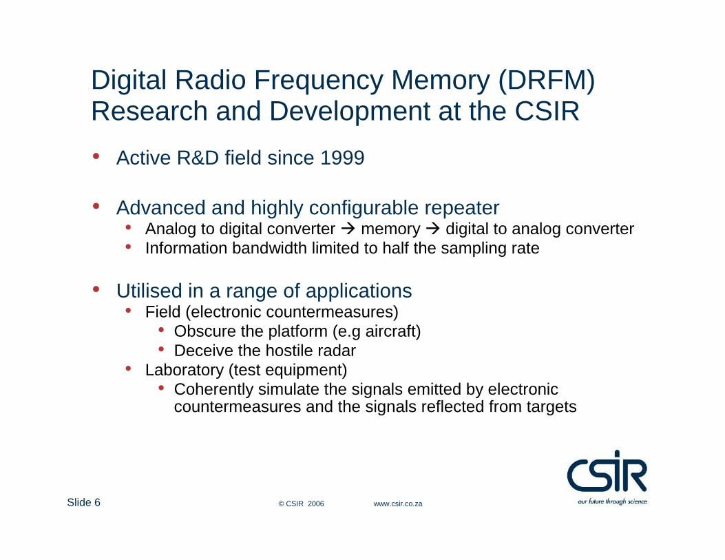
Digital Radio Frequency Memory (DRFM) Research and Development at the CSIR
• Active R&D field since 1999
• Advanced and highly configurable repeater• Analog to digital converter � memory � digital to analog converter• Information bandwidth limited to half the sampling rate
• Utilised in a range of applications• Field (electronic countermeasures)
• Obscure the platform (e.g aircraft)• Deceive the hostile radar
• Laboratory (test equipment)• Coherently simulate the signals emitted by electronic
countermeasures and the signals reflected from targets
Slide 7 © CSIR 2006 www.csir.co.za
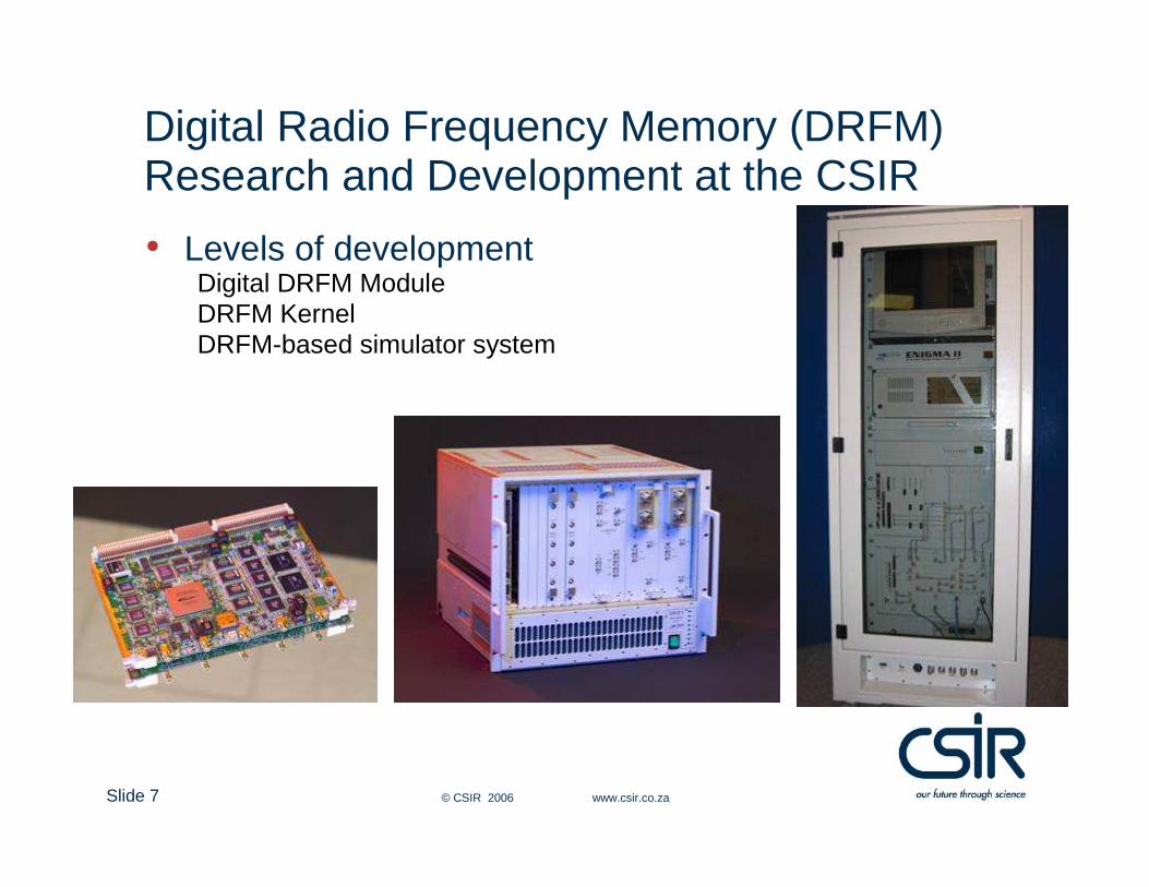
Digital Radio Frequency Memory (DRFM) Research and Development at the CSIR
• Levels of developmentDigital DRFM ModuleDRFM KernelDRFM-based simulator system

Slide 8 © CSIR 2006 www.csir.co.za
Need for Frequency Measurement in DRFM-Based Systems
• Pulse qualificationDeceive and obscure only hostile systems
• Frequency dependant techniquesAccurate Doppler responseRF bandwidth is a scarce resourceMaximise ECM effectiveness
• Compensate DRFM-induced phase perturbationsPoster presentation
Estimate required in less than a
microsecond

Slide 9 © CSIR 2006 www.csir.co.za
Frequency Measurement Solutions
• Instantaneous Frequency Measurement (IFM)• Analog technique• Combined with analog-to-digital
converter � DFD• Multiple parallel IFM’s• Single output• Dual aperture
• Discrete Fourier Transform (DFT)• Measures spectral response• Aliased to [0,fs/2) frequency
range• Multiple input signals• Multiple outputs
Preferred frequency estimation technique
Graph courtesy of AlteraTable taken from Schleher (1986)
Instantaneous Frequency Measurement Theory

Slide 11 © CSIR 2006 www.csir.co.za
Instantaneous Frequency MeasurementDigital Frequency Discriminator
AnalogInput
RL
I
Low-passFilter ADC
c0*arccos[c1*yfilt(tn)]
yfilt(tn) f0(tn)
DigitalOutput
Mixer
3 dBCoupler Analog
Delay lineLookup Table
• Multiply signal with delayed replica
• Low-pass filter
• Inverse cosine operation• Typically preceded with ADC• Lookup table• Digital Frequency Discriminator (DFD)
( ) ( ) ( )[ ]τππτπ 000
20 24cos2cos
8ftff
Atymix −+=
( ) ( ) ( ) ( ) ( )02 , 2cos08 00
20 HfHfH
Aty filt <<≈ τπ
( )( )
≈
0
8arccos
2
120
0 HA
tyf filt
πτ

Optimal Time Delay

Slide 13 © CSIR 2006 www.csir.co.za
Delay Line Calculation
• One-to-one mapping: Input frequency � output value• Maximum one-to-one input frequency calculated as
• Inverse of twice the maximum input frequency
• IFM with frequency range equal to ADC IBW• Unambiguous input frequency range [0,fs/2) chosen
• Optimal time delay = one ADC sampling period
( )( )
( )( )
( )0 ,
2
121
2
11arccos
2
1
max0max0max0
==+=−= nf
nff
πππ
τ
( )s
ss
tfff
==
== 1
22
1
2
1
max0
τ

Digital Instantaneous Frequency Measurement Basics

Slide 15 © CSIR 2006 www.csir.co.za
Steps 1&2: Sampling, Quantisation and Multiplication
• Sampling and quantisation
• Multiplication with time-delayed replica
( ) ( )[ ] ( )[ ]
( ) ( ) ( )nnFD
AnF
D
Around
f
fFnFAQn
f
fAQntyQny
qNN
sssq
εππ
ππ
+=
=
==
==
−0
00
10
0000
00
2cos22cos22
, 2cos2cos
( ) ( ) ( )
( ) ( )[ ]
( ) ( ) ( )[ ] ( ){ } ( ) ( )112cos12cos2
24cos2cos2
1
000
00012
2
20
−+−+−+
−+=
−=
−
nnnnFnnFD
A
FnFFD
A
nynyny
qqqqN
N
qqmix
εεεπεπ
πππ

Slide 16 © CSIR 2006 www.csir.co.za
Step 3: Low-Pass Filtering
• Finite Impulse Response (FIR) digital filter
where
( ) ( )
( ) ( ) ( ) ( )( )[ ] ( ) 22cos2cos02 0000012
2
20
0
nFHFnFFHFHD
A
knycny
qLPFLPFLPFN
N
kmixkfilt
επππ ′+′∠+−′′+=
−=
−
=∑
4 , 21
4 , 2
000
000
s
s
ffFF
ffFF
>−=′
≤=′

Slide 17 © CSIR 2006 www.csir.co.za
Step 3: Low-Pass Filtering
• Interactive filter design tools (e.g. MATLAB FDATool)
Slide 18 © CSIR 2006 www.csir.co.za
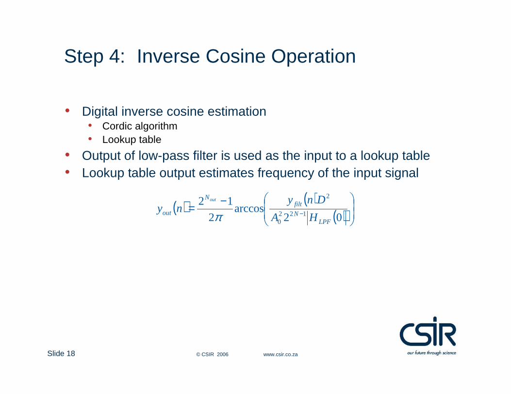
Step 4: Inverse Cosine Operation
• Digital inverse cosine estimation• Cordic algorithm• Lookup table
• Output of low-pass filter is used as the input to a lookup table• Lookup table output estimates frequency of the input signal
( ) ( )( )
−= − 02arccos
2
12122
0
2
LPFN
filtN
out HA
Dnyny
out
π

Slide 19 © CSIR 2006 www.csir.co.za
Digital Instantaneous Frequency Measurement
• Advantages
Mixing product relatively linear yielding lower spurious response
Filter response can be optimised for the specific requirements, i.e. fast response versus measurement accuracy
• Issues
FPGA clock speeds > 100 MHz
DIFM up to 50 MHz bandwidth with serial processing
Exhibit the same amplitude sensitivity as an analog IFM
Slide 20 © CSIR 2006 www.csir.co.za
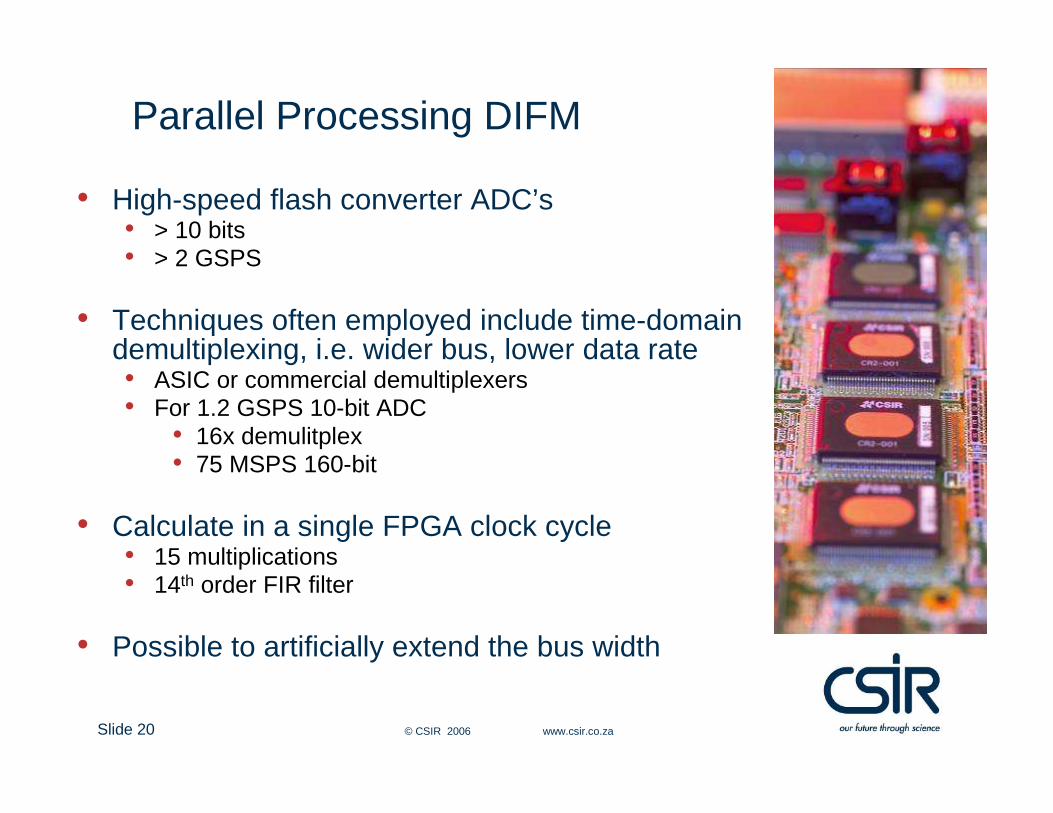
Parallel Processing DIFM
• High-speed flash converter ADC’s • > 10 bits • > 2 GSPS
• Techniques often employed include time-domain demultiplexing, i.e. wider bus, lower data rate• ASIC or commercial demultiplexers• For 1.2 GSPS 10-bit ADC
• 16x demulitplex• 75 MSPS 160-bit
• Calculate in a single FPGA clock cycle• 15 multiplications• 14th order FIR filter
• Possible to artificially extend the bus width
Slide 21 © CSIR 2006 www.csir.co.za
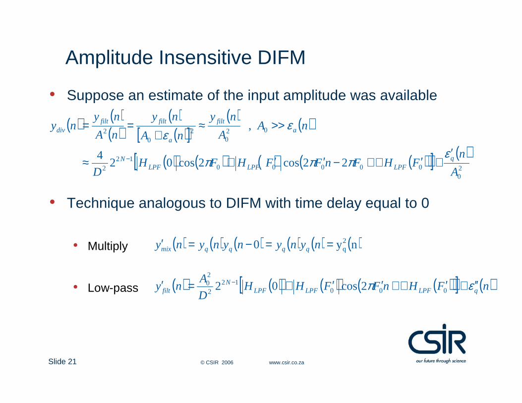
Amplitude Insensitive DIFM
• Suppose an estimate of the input amplitude was available
• Technique analogous to DIFM with time delay equal to 0
• Multiply
• Low-pass
( ) ( )( )
( )( )[ ]
( ) ( )
( ) ( ) ( ) ( )( )[ ] ( )20
0000012
2
020
20
2
22cos2cos024
,
A
nFHFnFFHFH
D
nAA
ny
nA
ny
nA
nyny
qLPFLPFLPF
N
afilt
a
filtfiltdiv
επππ
εε
′+′∠+−′′+≈
>>≈+
==
−
( ) ( ) ( ) ( ) ( ) ( )ny0 2q==−=′ nynynynyny qqqqmix
( ) ( ) ( ) ( )( )[ ] ( )nFHnFFHHD
Any qLPFLPFLPF
Nfilt επ ′′+′∠+′′+=′ −
00012
2
20 2cos02

Slide 22 © CSIR 2006 www.csir.co.za
Amplitude Insensitive DIFM
• Divide basic DIFM filter output with amplitude estimation
• Inverse cosine lookup table yield frequency estimation
• Advantages• Amplitude estimation exactly aligned with frequency estimation• No external calibration or alignment required• Time-domain multiplex hardware
( ) ( ) ( )( ) ( )( ) ( )
( )0
0000
0
2cos
22cos0
2cos
F
nFHFnFH
FHFny qLPF
LPF
LPFdiv
π
επππ
≈
′′′+′∠+−′′
+≈
( )s
lt f
fFny 0
0 22 ππ =≈

Example Implementation
Slide 24 © CSIR 2006 www.csir.co.za
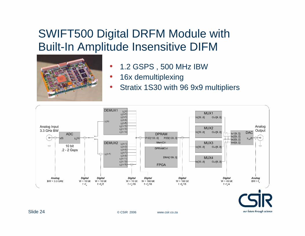
SWIFT500 Digital DRFM Module with Built-In Amplitude Insensitive DIFM
• 1.2 GSPS , 500 MHz IBW• 16x demultiplexing• Stratix 1S30 with 96 9x9 multipliers

Slide 25 © CSIR 2006 www.csir.co.za
SWIFT500 Digital DRFM Module with Built-In Amplitude Insensitive DIFM
yq(n)yq(n-1)
yq(n-15)
yq(n-2)
InputCast0InputCast1InputCast2
InputCast15UnitDelay0UnitDelay1UnitDelay2
UnitDelay15UnitDelay16UnitDelay17UnitDelay18
UnitDelay24
y'q(n-32)y'q(n-33)
y'q(n-40)
y'q(n-31)
y'q(n-18)y'q(n-17)y'q(n-16)
y'q(n-2)y'q(n-1)y'q(n)
y'q(n-15)
Uni
tD
elay
8
MuxMult24
14c0
22c1
38c2
57c3
81c4
109c5
138c6
168c7
196c8
221c9
240c10
252c11
255c12
252c13
240c14
221c15
196c16
168c17
138c18
109c19
81c20
57c21
38c22
22c23
14c24
y'q(
n-24
)y'
q(n-
25)
Flip-Flop
MuxMult1
MuxMult0
Adder
DeMux1Select
0 1
DeMux2Select
0 1
UnitDelay25
UnitDelay26
InverseLookupTable
Multiply
ArccosLookupTable
yout
y1mm
y2mm
y24mmya
UnitDelay25
ydm1 ydm2
ym
Mux#A
Mux#BSelect
0
1
Select
0
1y'q(n-#)
y'q(n-#-1)
y'q(n-#-16)
Select In
Multiply#A Multiply
#B
Coeff In #
Y#mm(m+d1)
Slide 26 © CSIR 2006 www.csir.co.za
SWIFT500 Digital DRFM Module with Built-In Amplitude Insensitive DIFM
• Key specifications• 9-bit multiplication • 24th order low-pass FIR filter with Chebyshev windowing• Cut-off frequency of 100 MHz and 48 dB side-lobe suppression• Frequency response 50 MHz to 550 MHz• Time-multiplexed resources to estimate amplitude and frequency• Division implemented in a two-step process
• Inversion of denominator using lookup table (12-bit x 12-bit)• Multiplication of numerator with inversed denominator
• 12-bit by 10-bit inverse cosine lookup table

Simulation Results
Slide 28 © CSIR 2006 www.csir.co.za
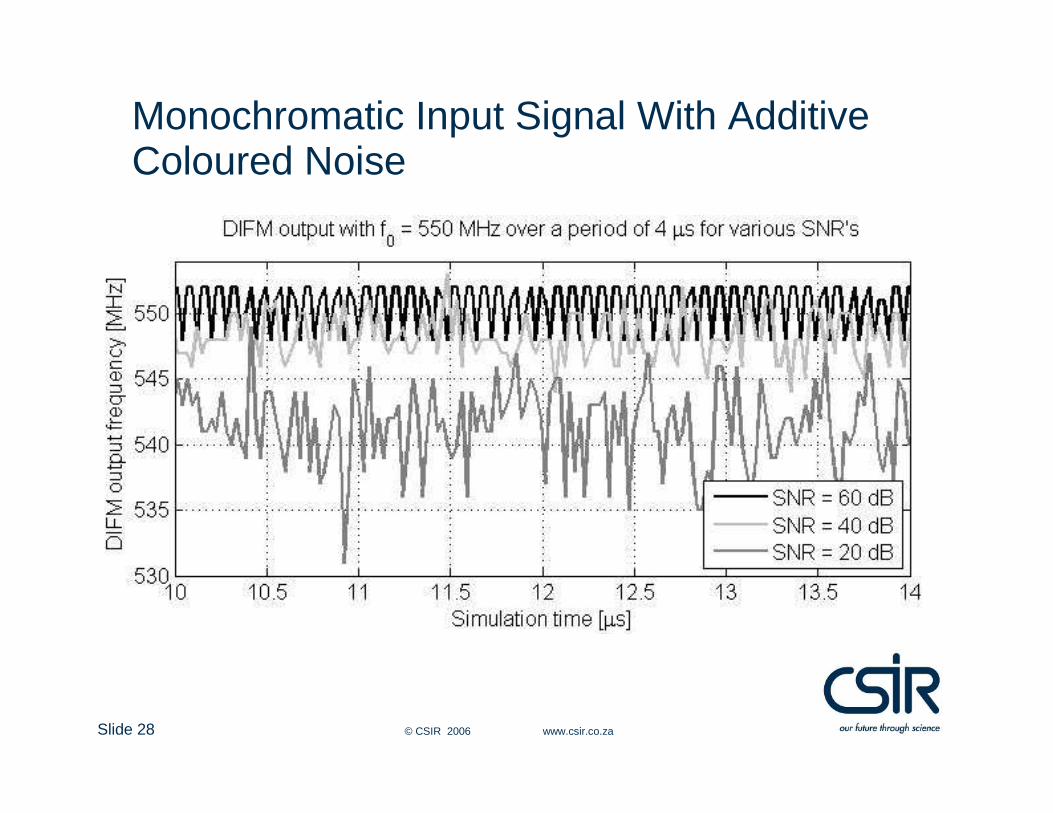
Monochromatic Input Signal With Additive Coloured Noise

Slide 29 © CSIR 2006 www.csir.co.za
Analysis of DIFM Accuracy

Slide 30 © CSIR 2006 www.csir.co.za
Key Performance Specifications• High signal-to-noise ratios
• Mean deviation less than ± 2 MHz• Absolute error less than 6 MHz across bandwidth• Absolute error less than 2 MHz in > 300 MHz bandwidth• RMS error less than 3 MHz across bandwidth• RMS error less than 1 MHz in > 300 MHz bandwidth
• Low signal-to-noise ratios• Bias in frequency estimation• Due to bias in amplitude estimation• Reduced by implementing higher order FIR filter (longer latency)
• Latency (processing time)• 13 FGPA clock cycles (173.33 ns)
• Throughput rate• 2 FGPA clock cycles (37.5 MHz)

Experimental Verification

Slide 32 © CSIR 2006 www.csir.co.za
Quantitative Laboratory Experiments
Conclusions

Slide 34 © CSIR 2006 www.csir.co.za
Conclusions
• Viable, shared aperture, frequency estimation technique• Implemented efficiently in current commercial hardware• Results comparable to existing analog techniques• Flexibility and ability to be optimised for the specific
requirements• Real-time changing the filter coefficients• Insensitive to temperature• Does not require periodic calibration to maintain accuracy• Operationally superior to its analog counterparts
• South African provisional patent application 2006/00946, 2006-02-01