A Design of Decoupling Structure MIMO Antenna for Mutual ...
3
A Design of Decoupling Structure MIMO Antenna for Mutual Coupling Reduction in 5G Application H. Yon¹, M.A Aris¹, N. H. Abd Rahman¹ ², N.A. M Nasir¹, H. Jumaat¹ ¹Antenna Research Centre (ARC), Faculty of Electrical Engineering, Universiti Teknologi MARA, Shah Alam, Selangor 40450, Malaysia. ²Malaysia Japan International Institute of Technology, Universiti Teknologi Malaysia, Jalan Sultan Yahya Petra, 54100, Kuala Lumpur, Malaysia [email protected] , [email protected], [email protected], [email protected], [email protected], Abstract— A new antenna structure with low mutual coupling between 2 antenna elements for MIMO has been developed and presented in this paper. The decoupling structure has been analyzed and designed between both antennas to suppress the isolation between dual elements. Nine different structures has been designed and 28.75% improvement on isolation has been achieved from pattern 3 decoupling structure. By using the decoupling structure, the antenna bandwidth has been improved tremendously to 20.8%. The antenna has been printed with full copper ground on the bottom layer. The antenna was simulated and optimized at 16 GHz using Computer Simulation Technology (CST) with permittivity, r = 2.2 and thickness, h = 1.57mm on Rodges RT- Duroid 5885 substrate. The antennas are matched at their corresponding frequency of operations. The simulation and fabrication results have shown that the antenna works well. Index Terms—MIMO, Decoupling Structure, CST, Rodges. I. INTRODUCTION Researchers have focused on the MIMO antenna because of its advantages especially on high capacity and high speed wireless communication[1]. Moreover, in the new era, there has been an increase in demand with MIMO antenna to support the growing number of devices that demands internet usages for 5G technology [2]. Therefore, there is a need to designing a compact antenna with multiple input and output. MIMO it’s the best configuration antenna that matches all the requirement for 5G technology. The crucial design challenge for MIMO antenna is to reduce mutual coupling. The traditional way to reduce mutual coupling is by separating antenna distance, however this method will increase the total size of the antenna. Decoupling structure is a method that can be used to reduce mutual coupling between antennas[3]. Further investigation on the concept of decoupling technique and it structure in order to improve mutual coupling and improve antenna performance are discussed in this paper. II. ANTENNA DESIGN 1 2 3 4 5 6 7 8 9 Figure 1. 9 decoupling structure pattern As shown from the Fig. 1, nine decoupling structures (pattern 1 to pattern 9) has been studied to improve antenna isolation. The width size (W) of the decoupling structure has been studied with 0.5mm, 1.0mm and 1.5mm, respectively. Each of the decoupling structure has its advantages as shows in Fig. 2 in term of isolation and bandwidth. Deeper analysis has been studied in[4]–[9] to design different shaped of decoupling structure in order to develop new structure and improvement MIMO performance in this research work. Size, mm 0.6 0.8 1.0 1.2 1.4 Isolation, dB -45 -40 -35 -30 -25 -20 -15 Decoupling Pattern 1 Decoupling Pattern 2 Decoupling Pattern 3 Decoupling Pattern 4 Decoupling Pattern 5 Decoupling Pattern 6 Decoupling Pattern 7 Decoupling Pattern 8 Decoupling Pattern 9 Bandwidth, GHz 1.4 1.5 1.6 1.7 Size, mm 0.6 0.8 1.0 1.2 1.4 Decoupling Pattern 1 Decoupling Pattern 2 Decoupling Pattern 3 Decoupling Pattern 4 Decoupling Pattern 5 Decoupling Pattern 6 Decoupling Pattern 7 Decoupling Pattern 8 Decoupling Pattern 9 Figure 2. Simulation for Isolation and bandwidth comparison
Transcript of A Design of Decoupling Structure MIMO Antenna for Mutual ...
A Design of Decoupling Structure MIMO Antenna
for Mutual Coupling Reduction in 5G Application
H. Yon¹, M.A Aris¹, N. H. Abd Rahman¹ ², N.A. M Nasir¹, H. Jumaat¹ ¹Antenna Research Centre (ARC), Faculty of Electrical Engineering, Universiti Teknologi MARA, Shah Alam, Selangor 40450,
Malaysia.
²Malaysia Japan International Institute of Technology, Universiti Teknologi Malaysia, Jalan Sultan Yahya Petra, 54100, Kuala
Lumpur, Malaysia
[email protected] , [email protected], [email protected], [email protected],
Abstract— A new antenna structure with low mutual coupling between 2 antenna elements for MIMO has been developed and presented in this paper. The decoupling
structure has been analyzed and designed between both antennas to suppress the isolation between dual elements. Nine different structures has been designed and 28.75%
improvement on isolation has been achieved from pattern 3 decoupling structure. By using the decoupling structure, the antenna bandwidth has been improved tremendously to
20.8%. The antenna has been printed with full copper ground on the bottom layer. The antenna was simulated and optimized at 16 GHz using Computer Simulation Technology (CST) with
permittivity, r = 2.2 and thickness, h = 1.57mm on Rodges RT-Duroid 5885 substrate. The antennas are matched at their corresponding frequency of operations. The simulation and
fabrication results have shown that the antenna works well.
Index Terms—MIMO, Decoupling Structure, CST, Rodges.
I. INTRODUCTION
Researchers have focused on the MIMO antenna because
of its advantages especially on high capacity and high speed
wireless communication[1]. Moreover, in the new era, there
has been an increase in demand with MIMO antenna to
support the growing number of devices that demands
internet usages for 5G technology [2]. Therefore, there is a
need to designing a compact antenna with multiple input
and output. MIMO it’s the best configuration antenna that
matches all the requirement for 5G technology. The crucial
design challenge for MIMO antenna is to reduce mutual
coupling.
The traditional way to reduce mutual coupling is by
separating antenna distance, however this method will
increase the total size of the antenna. Decoupling structure is
a method that can be used to reduce mutual coupling
between antennas[3]. Further investigation on the concept of
decoupling technique and it structure in order to improve
mutual coupling and improve antenna performance are
discussed in this paper.
II. ANTENNA DESIGN
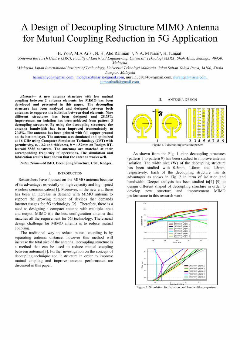
1 2 3 4 5 6 7 8 9
Figure 1. 9 decoupling structure pattern
As shown from the Fig. 1, nine decoupling structures
(pattern 1 to pattern 9) has been studied to improve antenna
isolation. The width size (W) of the decoupling structure
has been studied with 0.5mm, 1.0mm and 1.5mm,
respectively. Each of the decoupling structure has its
advantages as shows in Fig. 2 in term of isolation and
bandwidth. Deeper analysis has been studied in[4]–[9] to
design different shaped of decoupling structure in order to
develop new structure and improvement MIMO
performance in this research work.
Size, mm
0.6 0.8 1.0 1.2 1.4
Isol
atio
n, d
B
-45
-40
-35
-30
-25
-20
-15
Decoupling Pattern 1
Decoupling Pattern 2
Decoupling Pattern 3
Decoupling Pattern 4
Decoupling Pattern 5
Decoupling Pattern 6
Decoupling Pattern 7
Decoupling Pattern 8
Decoupling Pattern 9
Bandwidth, GHz
1.4 1.5 1.6 1.7
Siz
e, m
m
0.6
0.8
1.0
1.2
1.4
Decoupling Pattern 1
Decoupling Pattern 2
Decoupling Pattern 3
Decoupling Pattern 4
Decoupling Pattern 5
Decoupling Pattern 6
Decoupling Pattern 7
Decoupling Pattern 8
Decoupling Pattern 9
Figure 2. Simulation for Isolation and bandwidth comparison
Fig. 2 shows the relationship between decoupling size
and pattern towards isolation performance. From the figure,
decoupling structure with Pattern 3, size 0.5mm shows
value in terms of isolation compared with other structure.
The improvement 28.75% of isolation has been achieved
from this pattern compared with antenna without decoupling
structure in simulation process.
III. RESULT
Figure 3. Simulation reflection coefficient comparison
Figure 4. Simulation isolation comparison
Figure 5. Simulation radiation pattern comparison
The simulation result for the antenna with decoupling
structure Pattern 3 is shown in Fig. 3, Fig. 4 and Fig. 5.
From the result, it has shown that the decoupling structure
with 0.5mm size has improved isolation better compared to
the 1.0mm and 1.5mm. As a result, the final antenna will
fabricated and measured with a 0.5mm decoupling size.
Fig. 6 shows the antenna reflection coefficient that has
been measured using Vector Network Analyzer. The antenna
has been measured in order to determine the feasibility of the
fabricated design. The antenna without decoupling was -
18.44dB at 16.02GHz for port 1 and -18.34 on port 2 at
15.94GHz. Meanwhile, for antennas with decoupling
structure are reduce to -12.94dB at port 1 and -12.05 at port
2. The reflection coefficient are reduced, this is due to
improper on fabricated process and handling antenna
structure during measurement process.
Figure 6. Measurement result (a) without (b) with decoupling
Meanwhile, Fig. 7 shows good results at the isolation
between antenna where the antenna isolation is achieved at -
31.28dB with decoupling structure and -26.76dB without
decoupling structure.
Figure 7. Measurement result (a) without (b) with decoupling
The radiation pattern was measured in an indoor anechoic
chamber using the Far-field measurement at selected
operating frequency. The fabricated antenna exhibits a
dominant wave distribution at E-Plane with a simulated
radiation pattern that radiates at 0º angle. The radiation
pattern measurement has been held in E-Plane condition and
also in H-Field to ensure antenna radiation pattern same as a
simulated result.
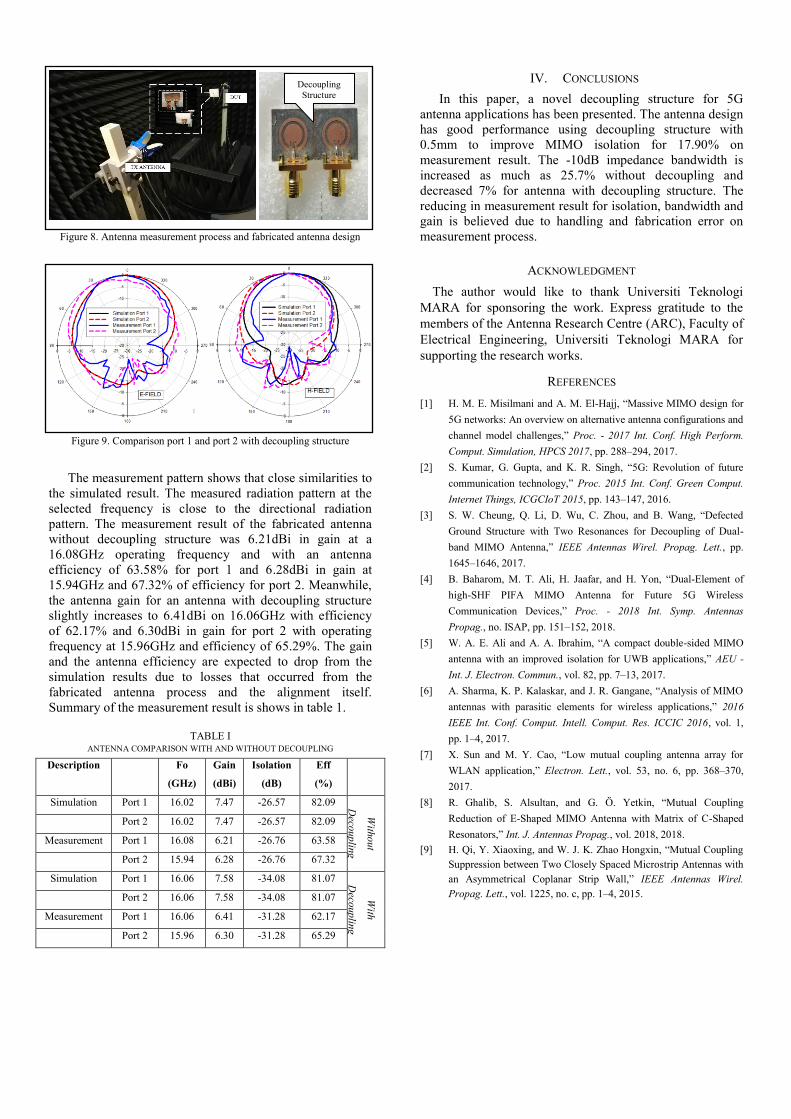
Figure 8. Antenna measurement process and fabricated antenna design
Figure 9. Comparison port 1 and port 2 with decoupling structure
The measurement pattern shows that close similarities to
the simulated result. The measured radiation pattern at the
selected frequency is close to the directional radiation
pattern. The measurement result of the fabricated antenna
without decoupling structure was 6.21dBi in gain at a
16.08GHz operating frequency and with an antenna
efficiency of 63.58% for port 1 and 6.28dBi in gain at
15.94GHz and 67.32% of efficiency for port 2. Meanwhile,
the antenna gain for an antenna with decoupling structure
slightly increases to 6.41dBi on 16.06GHz with efficiency
of 62.17% and 6.30dBi in gain for port 2 with operating
frequency at 15.96GHz and efficiency of 65.29%. The gain
and the antenna efficiency are expected to drop from the
simulation results due to losses that occurred from the
fabricated antenna process and the alignment itself.
Summary of the measurement result is shows in table 1.
TABLE I ANTENNA COMPARISON WITH AND WITHOUT DECOUPLING
Description Fo
(GHz)
Gain
(dBi)
Isolation
(dB)
Eff
(%)
Simulation Port 1 16.02 7.47 -26.57 82.09
With
out
Deco
up
ling
Stru
cture
Port 2 16.02 7.47 -26.57 82.09
Measurement Port 1 16.08 6.21 -26.76 63.58
Port 2 15.94 6.28 -26.76 67.32
Simulation Port 1 16.06 7.58 -34.08 81.07
With
Deco
up
ling
Stru
cture
Port 2 16.06 7.58 -34.08 81.07
Measurement Port 1 16.06 6.41 -31.28 62.17
Port 2 15.96 6.30 -31.28 65.29
IV. CONCLUSIONS
In this paper, a novel decoupling structure for 5G
antenna applications has been presented. The antenna design
has good performance using decoupling structure with
0.5mm to improve MIMO isolation for 17.90% on
measurement result. The -10dB impedance bandwidth is
increased as much as 25.7% without decoupling and
decreased 7% for antenna with decoupling structure. The
reducing in measurement result for isolation, bandwidth and
gain is believed due to handling and fabrication error on
measurement process.
ACKNOWLEDGMENT
The author would like to thank Universiti Teknologi
MARA for sponsoring the work. Express gratitude to the
members of the Antenna Research Centre (ARC), Faculty of
Electrical Engineering, Universiti Teknologi MARA for
supporting the research works.
REFERENCES
[1] H. M. E. Misilmani and A. M. El-Hajj, “Massive MIMO design for
5G networks: An overview on alternative antenna configurations and
channel model challenges,” Proc. - 2017 Int. Conf. High Perform.
Comput. Simulation, HPCS 2017, pp. 288–294, 2017.
[2] S. Kumar, G. Gupta, and K. R. Singh, “5G: Revolution of future
communication technology,” Proc. 2015 Int. Conf. Green Comput.
Internet Things, ICGCIoT 2015, pp. 143–147, 2016.
[3] S. W. Cheung, Q. Li, D. Wu, C. Zhou, and B. Wang, “Defected
Ground Structure with Two Resonances for Decoupling of Dual-
band MIMO Antenna,” IEEE Antennas Wirel. Propag. Lett., pp.
1645–1646, 2017.
[4] B. Baharom, M. T. Ali, H. Jaafar, and H. Yon, “Dual-Element of
high-SHF PIFA MIMO Antenna for Future 5G Wireless
Communication Devices,” Proc. - 2018 Int. Symp. Antennas
Propag., no. ISAP, pp. 151–152, 2018.
[5] W. A. E. Ali and A. A. Ibrahim, “A compact double-sided MIMO
antenna with an improved isolation for UWB applications,” AEU -
Int. J. Electron. Commun., vol. 82, pp. 7–13, 2017.
[6] A. Sharma, K. P. Kalaskar, and J. R. Gangane, “Analysis of MIMO
antennas with parasitic elements for wireless applications,” 2016
IEEE Int. Conf. Comput. Intell. Comput. Res. ICCIC 2016, vol. 1,
pp. 1–4, 2017.
[7] X. Sun and M. Y. Cao, “Low mutual coupling antenna array for
WLAN application,” Electron. Lett., vol. 53, no. 6, pp. 368–370,
2017.
[8] R. Ghalib, S. Alsultan, and G. Ö. Yetkin, “Mutual Coupling
Reduction of E-Shaped MIMO Antenna with Matrix of C-Shaped
Resonators,” Int. J. Antennas Propag., vol. 2018, 2018.
[9] H. Qi, Y. Xiaoxing, and W. J. K. Zhao Hongxin, “Mutual Coupling
Suppression between Two Closely Spaced Microstrip Antennas with
an Asymmetrical Coplanar Strip Wall,” IEEE Antennas Wirel.
Propag. Lett., vol. 1225, no. c, pp. 1–4, 2015.
Decoupling
Structure


![Decoupled Integral LQR Controller with Anti-windup ...jestec.taylors.edu.my/Vol 14 issue 3 June 2019/14_3_20.pdf · decoupling control [1]. The interaction in a MIMO system makes](https://static.fdocuments.us/doc/165x107/5e6b5f9434160e64ed220e72/decoupled-integral-lqr-controller-with-anti-windup-14-issue-3-june-201914320pdf.jpg)