
A Design Library of Magnet Supports - A Proposal
18
II/233 SLAC Pub 7061 A DESIGN LIBRARY OF MAGNET SUPPORTS -A PROPOSAL-* ROBERT E. RULAND # Stanford Linear Accelerator Center, Stanford University, Stanford, CA 94309 Preface Although the ideal and universal support system has not been invented yet, there are many implementations which fulfill most of alignment’s requirements. However, inventing a new support system seems to represent the last design challenge, why would we otherwise witness so many new attempts. Already Plato reminded his scholars that one should learn from the past. Unfortunately, learning from previous designs and implementations doesn’t seem to carry much attraction. Or it is that we, the customers, are not doing our job by letting the design engineer know what we would like to see done, what we think works, and what is already there. This contribution is an initiative to create a reference for support systems which exist in our laboratories and we know do work. Such an undertaking will require everybody’s active support and feedback. I already have to thank my peers at many laboratories who helped me put together this first draft. Only if a more or less complete library of existing designs can be compiled with easy ac- cess to drawings can we then hope that the support system design competition looses its challenge. 1.0 Introduction As alignment tolerances get ever tighter, the interplay of alignment with mechanical engi- neering becomes ever more important. In fact, accelerator alignment has advanced so far that me- chanical uncertainties now exceed observational uncertainties. Of the mechanical issues bearing * Work supported by Department of Energy contract DE-AC03-76SF005 15 # Author e-mail: [email protected] and FAX: (415) 926-4055
Transcript of A Design Library of Magnet Supports - A Proposal
II/233
SLAC Pub 7061
A DESIGN LIBRARY OF MAGNET SUPPORTS
-A PROPOSAL-*
ROBERT E. RULAND#
Stanford Linear Accelerator Center, Stanford University, Stanford, CA 94309
Preface
Although the ideal and universal support system has not been invented yet, there are many
implementations which fulfill most of alignment’s requirements. However, inventing a new support
system seems to represent the last design challenge, why would we otherwise witness so many new
attempts. Already Plato reminded his scholars that one should learn from the past. Unfortunately,
learning from previous designs and implementations doesn’t seem to carry much attraction. Or it is
that we, the customers, are not doing our job by letting the design engineer know what we would
like to see done, what we think works, and what is already there.
This contribution is an initiative to create a reference for support systems which exist in our
laboratories and we know do work. Such an undertaking will require everybody’s active support and
feedback. I already have to thank my peers at many laboratories who helped me put together this
first draft. Only if a more or less complete library of existing designs can be compiled with easy ac-
cess to drawings can we then hope that the support system design competition looses its challenge.
1.0 Introduction
As alignment tolerances get ever tighter, the interplay of alignment with mechanical engi-
neering becomes ever more important. In fact, accelerator alignment has advanced so far that me-
chanical uncertainties now exceed observational uncertainties. Of the mechanical issues bearing
* Work supported by Department of Energy contract DE-AC03-76SF005 15
# Author e-mail: [email protected] and FAX: (415) 926-4055

II/234
upon alignment, one of the most crucial is the magnet supports; these must provide both stability
and a fineness of motion substantially exceeding the final alignment tolerances.
Magnet supports are the interface that allows mechanical mounting of components and their
subsequent alignment to a nominal position in three-dimensional space. Supports thus provide two
functions: that of a spacer to bring the component close to its ideal position, and that of a fine mo-
tion system to enable the surveyor to move the component to its ideal location within the required
tolerance.
It is essential to understand that Magnets, Supports, and Survey and Alignment are interre-
lated. Ideally, one person would be responsible for all these functions. In larger projects, beyond the
scope of one such manager, the responsible parties must be in regular communication. A magnet
designed without supports in mind can be quite impossible to hold onto.1 A support system that
holds the magnets up, but requires a hammer to operate, renders impossible the achievement of tight
tolerances. Magnets, Supports, and Survey and Alignment must be designed as a system.
1.1 Space r s
Components, with their adjustment systems, are rarely mounted directly to the floor or to an
elevated concrete structure. Instead, girders or individual stands are used to hold a component at its
approximate position and elevation above the floor. These spacers serve as the backbone on which
the more precisely machined adjustment systems can be mounted.
1.1.1 Girders
A girder is a strongback or platform onto which a group of components can be mounted at
beam height. Girders simplify the installation in cases when many small components need to be
supported immediately adjacent to one another. The major advantages of a girder support system
over individual stands are:
• The girder isolates individual components from ground settlements, since the whole group of
components moves up or down together. Any settlement can be corrected by adjusting the posi-
tion of one girder, rather than many support stands.

II/235
• To bring the magnet poles as close as possible to the beam in the latest generation of machines,
the clearance between the pole tips and the vacuum chamber is very small, allowing little motion
of the magnet with respect to the chamber. A global position adjustment of individual compo-
nents requires many iterations and much time, unless all the components are mounted together
and move as one monolith.
• As vacuum chambers become increasingly complex, it is often impossible to achieve and retain
the correct shape in the production process. Whereas magnet supports should generally be kine-
matic (i.e., provide only the minimal number of constraints), for vacuum chambers, a heavily
overconstrained system is often required so that the chamber can be pushed and pulled into
shape. Such a system will work satisfactorily only if all constraints connect to the same refer-
ence body. This eliminates the use of individual stands.
• Girders can be filled with water to increase their thermal capacity, thereby slowing the rate of
response of the girder to temperature variations.
• Girders can be preassembled in a shop before installation. All of the magnets and the vacuum
chamber for a girder are installed and aligned to the final relative tolerance in a local girder co-
ordinate system. Water-cooling manifolds and hoses are assembled on the girder at this stage, as
are the connections of electrical circuits. All this work can be done in a production line envi-
ronment rather than the tunnel, making it more efficient and of higher quality, with a more reli-
able inspection.2 Installation of the preassembled girder in the tunnel is also significantly faster.
There are two primary types of girders: steel box and concrete. Concrete girders (Fig. 1)
feature two I-beams cast into a rectangular cement block and machined flat. The rail system formed
by the I-beams supports the beam line components. This system is widely used at SLAC. Concrete
girders have a significant cost advantage, but great care must be taken during the construction and
cement curing process, for slow creep and hairline cracking can severely hamper the monolithic
quality of the finished girder. The other girder type (Fig. 2) is the stress-relieved structural-steel box
girder. During the machining of the top and bottom plates, all the mounting holes can be quickly,
cheaply, and accurately drilled and tapped by NC machines, obviating the need for lengthy prea-
lignment and for manual drilling and tapping of mounting holes.

II/236
Fig. 1. Concrete girder as used in SLAC Final Focus.
Fig. 2. Steel girder as used in LBL ALS. Photo courtesy of Lawrence Berkeley Laboratory,University of California
1.1.2 Individual Stands
Individual stands are generally used in situations where components are more spread out; e.g.,
transport lines. The simplest form of stand is a length of pipe with plates welded to the top and bot-
tom (Fig. 3). The diameter of the pipe is of course a function of stand height and component load.

I I /237
Fig. 3. Individual steel stand
More sophisticated stands are used at SLAC in the
FFTB. These stands are made of Anocast, a granite
epoxy which gives the stands the appearance of a
granite block molded to the specifications of the par-
ticular application.3 In effect, the Anocast stands be-
come a hybrid of stand and girder. In the FFTB some
Anocast stands support a group of magnets while still
maintaining the typical cross section of an individual
magnet stand (Fig. 4a and 4b). Measurements con-
firm that these stands have much better damping
qualities of vibrations at higher frequencies than steel
stands. Furthermore, their thermal mass dampens ex-
pansion due to variations in the ambient temperatures.
Costs for steel and Anocast stands are comparable.
1.2 M a n u a l A d -
justment Systems
All beam compo-
nents need to be moved
and fixed at accurate lo-
cations by adjustment
mechanisms. These sys-
tems should include the
following design fea-
tures:
Fig. 4a and 4b. Anocast stands in SLAC FFTB

I I / 2 3 8
• Adequate alignment precision: for precise adjustibility, the system’s resolution should be ten
times the required alignment tolerance.
• Orthogonal motion: there should be no cross coupling between the axes for small adjustment
motions. For large motions, any existing coupling must be predictable.
• Kinematic mount: an overconstrained system induces stress into the support and/or component,
resulting in a deformation of the component.
• Stability: the support should provide a stiff base when locked down where incidental contact
will not cause movement of the magnet. It should also not deform the component during adjust-
ment.
• A small footprint: as real estate is usually at a premium, components must often be placed very
close together.
• Vibrational stiffness: typical ground motion frequencies should not be amplified by the support
system.
There are two general types of adjustment mechanisms. The most common type separates
the horizontal adjustment from the vertical degree of freedom. The second type combines horizontal
and vertical adjustments into one system, usually implemented in a six strut layout that holds the
component in a kinematic suspension. Other implementations are the CERN Adjuster System and
its derivative, the CEBAF 3-D Cartridge, and the SLAC 3-D stage.
1.2.1 One and Two-Dimension Systems
To separate the horizontal from the vertical, a horizontal plane is generated by adjusting the
height of three vertical standoffs. In its simplest implementation, the standoffs are either shim stacks
or threaded rods. In the case of shim stacks, shim stock is added or removed until the plate is hori-
zontal and the component at its ideal height, a lengthy, iterative process. Where threaded rods are
used, the mounting plate rides on three screw nuts that are threaded on vertically mounted rods.
Turning the nuts provides vertical translations along the Y-axis and two rotational degrees of free-
dom, pitch (rotation around the X-axis), and roll (rotation around the Z-axis).

II/239
On this horizontal plate slide one or two plates on which the component is mounted. These
plates move under the force of adjustment screws to adjust and fix the Z (in beam direction), X
(perpendicular to Z), and yaw (rotation around the Y-axis) degrees of freedom. The adjustment
screws are often designed in a push-push arrangement (Fig. 5) with two opposing screws pushing on
both sides of the component in a colinear arrangement. To achieve a translation, one side is loos-
ened and the other tightened. Tightening both screws locks the position. Often the stand has only
one sliding plate; in this case, the X and Z adjustments are not independent, since all adjustment
screws must be loosened to permit sliding of the plate. Fine adjustment in the orthogonal direction is
usually lost, and must be touched up again. Precise alignment with only a single sliding plate and
push-push screw arrangement usually requires many iterations.
Fig. 5. Push-push screw arrangement
This basic design can be refined by replacing the above described horizontal and vertical
adjuster with more sophisticated variations. The addition of spherical washers between the horizon-
tal plate and the adjustment nuts makes the system move more smoothly. If the system is designed
to carry higher loads, machine screw jacks (Fig. 6) are available that fit almost any application while
still providing fine adjustment motion. Less expensive, but more limited in range, are wedge jack
adjusters that are made of two wedges with the two sloped planes riding on each other. A horizontal
motion pushes the upper wedge higher on the inclined plane, thereby providing a vertical motion.
Wedge jack adjusters are available off the shelf in many load travel combinations. The push-push

II/240
Fig. 6 Machine screw jack support.
Six-strut system A kinematic suspension can be
created by arranging six adjustable length links
in a 3-D truss. The three vertical struts adjust
and hold the vertical translation, and the pitch
and roll rotations. The three other struts (Fig. 8)
are placed in the horizontal plane, two in one
direction, and the third perpendicular. These
three adjust and hold the X and Z translations
and the yaw rotation. The orthogonal arrange-
ment of the struts minimizes coupling in motion.
Struts are length-adjustable rigid members with
spherical joints at each end. A strut will support
screw arrangement can be improved by a
turnbuckle/rail-slide design. The two push
screws are replaced by one turnbuckle,
which provides both the push and pull
force. The fixed end of the turnbuckle can
slide on a rail oriented parallel to the other
adjustment axis in order to allow two-
dimensional adjustments. This design is
still relatively simple and inexpensive,
while complying with all the above listed
requirements. To support the girders in
the storage ring of the Argonne Photon
Source, a combination of wedge jack ad-
justers (Fig. 7) and turnbuckle-type hori-
zontal adjustment was used.
1.2.2 Three-Dimension Systems
Fig. 7. Wedge jack adjuster as use in APS

II/241
only an axial load, in axial compression or
tension. The spherical joints at either end en-
sure that a strut never experiences loads in
any other direction. Since all struts are in
axial compression or tension, they provide
very rigid support.
1.2.3 Typical System Implementations
Advanced Light Source (ALS) strut
system. All components and girders at the
Advanced Light Source at the Lawrence Ber- Fig. 8. Kinematic suspension
keley Laboratory are supported by strut systems4 (Fig. 9), as is the Spherical Grating Monochroma-
tor at the SSRL. The struts used for the support systems are not normal stock items. To avoid the
backlash present in all regular spherical joints, the spherical rod end bearings have been squeezed in
a controlled way to generate friction, which only a specific break-away torque can overcome. A
shaft collar has been added at the end of each tube into which the rod end bearings thread. A portion
Fig. 9. ALS strut supports. Photo courtesy of Lawrence Berkeley Laboratory, University of California

II/242
of the tube, at each end, is turned down and slit in two directions so the shaft collar will squeeze the
female thread against the male thread of the rod ends to remove any backlash in the threads. The rod
end bearings are all right-hand threads with one coarse thread and the other a fine thread. creating a
differential threaded device which allows very high resolution adjustments. For the support of heavy
Fig. 10. ALS 5-ton machine screw jack strut. Fig. 11. ALS 20-ton machine screw jack strut.
Photos courtesy of Lawrence Berkeley Laboratory. University of California.
loads, the tube and differential threads are replaced by an appropriately rated machine screw jack
(Figs. 10, 11).
CERN cartridge. The CERN Adjuster System5 consists of three cartridges that utilize a combination
of the principles in the two styles discussed above. The improvement over the first style mechanism
is that the sliding feature is replaced by the three vertically-oriented links of the kinematic suspen-
sion. The first or main cartridge works as follows (Fig. 12): the piston-ended link pivots in a socket
at the bottom of the base and floats within a hollow cylindrical projection from that base. At the top,
II/243
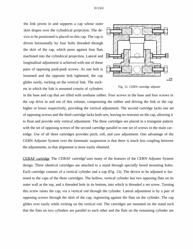
the link pivots in and supports a cap whose outer
skirt drapes over the cylindrical projection. The de-
vice to be positioned is placed on this cap. The cap is
driven horizontally by four bolts threaded through
the skirt of the cap, which press against four flats
machined into the cylindrical projection. Lateral and
longitudinal adjustment is achieved with one of these
pairs of opposing push-push screws. As one bolt is
loosened and the opposite bolt tightened, the cap
glides easily, rocking on the vertical link. The sock-
ets in which the link is mounted consist of cylindersFig. 12. CERN cartridge adjuster
in the base and cap that are tilled with urethane rubber. Four screws in the base and four screws in
the cap drive in and out of this volume, compressing the rubber and driving the link or the cap
higher or lower respectively, providing the vertical adjustment. The second cartridge lacks one set
of opposing screws and the third cartridge lacks both sets, leaving no restraint on the cap, allowing it
to float and provide only vertical adjustment. The three cartridges are placed in a triangular pattern
with the set of opposing screws of the second cartridge parallel to one set of screws in the main car-
tridge. Use of all three cartridges provides pitch, roll, and yaw adjustment. One advantage of the
CERN Adjuster System over the kinematic suspension is that there is much less coupling between
the adjustments, so that alignment is more easily obtained.
CEBAF cartridge The CEBAF cartridge6 uses many of the features of the CERN Adjuster System
design. Three identical cartridges are attached to a stand through specially bored mounting holes.
Each cartridge consists of a vertical cylinder and a cap (Fig. 13). The device to be adjusted is fas-
tened to the caps of the three cartridges. The hollow, vertical cylinder has two opposing flats on its
outer wall at the top, and a threaded hole in its bottom, into which is threaded a set screw. Turning
this screw raises the cap, via a vertical rod through the cylinder. Lateral adjustment is by a pair of
opposing screws through the skirt of the cap, registering against the flats on the cylinder. The cap
glides over easily while rocking on the vertical rod. The cartridges are mounted on the stand such
that the flats on two cylinders are parallel to each other and the flats on the remaining cylinder are

II/244
Fig. 13. CEBAF cartridge adjuster
Fig. 14. SLAC Damping Ring girder support
perpendicular to the other two, providing lateral, longitudi-
nal, and yaw adjustment. With this orientation, all degrees of
freedom are constrained with no overconstraint. Locking of
the movement of all screw threads is provided by locknuts.
SLAC damning ring girder support This design contains the most basic adjustment system con-
struction elements, a push-push screw arrangement combined with a threaded rod7 (Fig. 14). The
girder is supported by three feet. Each foot’s baseplate is bolted and grouted to the floor in an ap-
proximately horizontal position. Atop this baseplate sits a sliding plate that can be moved relative to
the baseplate by the force of a two-dimensional push-push screw arrangement. A short fine-threaded
rod of substantial diameter is mounted to the sliding plate at its center. A cap-shaped nut, riding on
the threads over the top of the rod, provides the vertical adjustment. The girder is mounted to this
nut in a way which prevents any horizontal backlash, while still permitting it to be turned. The sys-
tem is locked in the horizontal dimension by a bolt holding the sliding plate to the baseplate, and in
the vertical dimension by a set screw which prevents the cap nut from turning. While this system
allows relatively high resolution adjustment of heavy loads, the total system is significantly over-
constrained, and must therefore be operated with great caution.
SLAC Final Focus girder support This design is similar to the Damping Ring supports. but avoids
the overconstraints8 (Fig. 15). The push-push screw arrangement is replaced by one-dimensional
stages: two feet have stages oriented for lateral adjustment, while the stage at the third foot provides
longitudinal motion. To decouple the cross-motion between stages, the supports are fixed

II/245
to the girder in only one horizontal dimension, which is accomplished by a rail slide system. The
vertical adjustment is functionally the same as on the support discussed above.
Fig. 15. SLAC Final Focus girder support Fig. 16 CERN LEP Dipole support
CERN LEP dipole support This system9 can provide kinematic support to a wide variety of appli-
cations, from small magnets to heavy girder modules. The general idea and functionality are taken
from the CERN cartridge design, but with the vertical adjustment replaced by an adjustable-length
link (Fig. 16). To minimize motion correlation, the link is made as long as possible, subject to the
restraints of the specific application.
SLAC 3-D stage This is an adjustment system tailored to support a variety of components, from
small quadrupoles to long narrow bends that are to be positioned to tight tolerances10 (Fig. 17). The
horizontal degrees of freedom are provided by a baseplate/sliding plate arrangement. To avoid over-
constraint, the adjustment motion is created by three semitumbuckles, in which one end is a conven-
tional rod end bearing, but the other end is a threaded stud (Fig. 18). Two of these semitumbuckles
provide the lateral adjustment, and a third gives the longitudinal adjustment. The spherical rod end
bearings are threaded into blocks bolted to the base plate. The spherical bearing end is threaded onto
a rail that is mounted on the baseplate perpendicular to the rod’s adjustment direction. This arrange-
ment allows the sliding plate to be adjusted in one dimension, while maintaining the adjustment in
the other horizontal dimension. The vertical adjustment is created in a similar way. Three spherical

II/246
Fig. 17. SLAC 3-D stage
Fig. 18. Lateral adjustment layout
rod end bearings are bolted vertically into blocks
mounted to the sliding plate. Bolts through the
spherical rod end bearings support the component.
DESY PETRA single component support sys-
tem This system has been used to support quad-11
rupoles on single stands and long dipoles on two
single stands at either magnet end in the PETRA
ring. The underlying scheme is now widely used in
other machines at DESY. Shown below in Fig. 19 is
a quadrupole sitting with three pads on three vertical
screws that provide height, roll, and pitch adjust-
ments. In the horizontal plane, two struts allow mo-

I I /247
tion perpendicular to the beam. No adjust-
ment capability along the beam axis is
provided. To create a kinematic mount
between the pads and screws, one screw
head is resting in a groove, while the other
two pads are flat.
Fig. 19. DESY PETRA support system 1.3 Motorized Adjustment Systems
SLAC FFTB magnet positioners The FFTB magnet positioners12 differ from conventional position-
ing stages used in instruments and machine tools. The mechanism is designed to support loads ex-
ceeding 1 ton, while still providing smooth motion, free of hysteresis, at the micron level. The de-
sign is simple and sufficiently reliable for large scale use in the remote positioning of hundreds of
magnets. Conventional crossed-slide leadscrew positioning stages are not appropriate for this appli-
cation. High-resolution piezoelectric positioners13 cannot meet the load and range requirements.
The remote magnet positioning mounts used in the FFTB kinematically support the magnets on
roller cams. The magnet rests under gravity in a cradle formed by the cams (Fig. 20). This type of
kinematic support is similar to the Kelvin Clamp14 used in laboratory optics and instrumentation.
The V-blocks and flat plates fixed to the magnet make point or line contact with the outer bearing
races of the roller cams. Rotation of the eccentric cam-
shafts shifts the magnet position. This type of kinematic
support, where the number of contact points balances
the number of degrees of spatial freedom, has the ad-
vantage of avoiding all free play between the magnet
and mount. The magnet always rests in contact with all
of the supporting cams, regardless of their position. No
precise mechanical dimensions are needed to insure
zero play. No clamping forces, other than gravity, can
distort the magnet’s shape. The magnet can be removed
from the mount and replaced without realignment. Fig. 20. Magnet positioning mount with roller cams

II/248
During operation, only the inner eccentric shaft of a support cam rotates under motor control. The
outer cam bearing race remains in contact with the magnet as shaft rotation lifts the magnet. In such
a system, failure of the control system will only cause the cam to cycle around again. Magnet mo-
tions are strictly bounded by the design geometry. Limit switches are not needed for over-travel
protection. All support cams are arranged so that gravity applies a load torque to each cam shaft
drive train. This torque removes all backlash, except at the extremes of cam lift. All parts move by
pure rolling motion, and are free of the hysteresis typical of intermittent and reversing sliding mo-
tion. This mount can adjust the horizontal and vertical position of the magnet, as well as the mag-
net’s roll angle around the beam axis. The magnet’s longitudinal position along the beam line, as
well as its alignment to the beam direction in this implementation are fixed in the support mount,
and not remotely adjustable. Figure 21 shows the three-motor positioning mount used to support
FFTB quadrupole magnets. Kinematic roller cam supports can be applied to a variety of geometries.
The barrel containing the final triplet of quadrupole lenses for the Stanford Linear Collider is sup-
ported on five roller cam supports. This 5-m-long 6-ton assembly is remotely adjustable in pitch and
yaw, as well as roll, vertical, and horizontal position.
Fig. 21. FFTB magnet remote positioner
II/249
ESRF servo-controlled jacks Predicted ground motion of more than 1 mm per year led to the devel-
opment of a remote vertical alignment system. A computer-controlled hydrostatic leveling system
was installed in the storage ring with three measurement stations on each girder. These girders are
kinematically supported by three vertical motorized screw jacks, which are interfaced to the control
system. The horizontal adjustment is provided by a gear-driven X-Z stage mounted on top of the
vertical jacks.15 First results indicate that it takes about two minutes to map the entire ring, and then
only two hours to vertically align all girders.16
References
1. Ted Lauritzen, “The ALS Six Strut Support System,” presentation at the Pohang Light
Source Laboratory (Pohang, September 1992), p. 4.
2. Conceptual Design Report, 1-2 GeV Synchrotron Radiation Source (Lawrence Berkeley
Laboratory, Berkeley, July 1986) p. 77.
3. Anocast, a Division of Anorad Corp., 110 Oser Ave., Hauppauge, NY 11788.
4. Ted Lauritzen, private communication.
5. Michel Mayoud, private communication.
6. George Biallas, private communication.
7. Charles Perkins, private communication.
8. Bill Davies-White, private communication.
9. Michel Mayoud, private communication.
10. Dieter Walz, private communication.
11. Willfried Schwarz, private communication.
12. Gordon Bowden, private communication.
13. A. Bergamin et al., “Servopositioning with Picometer Resolution,” Rev. Sci. Instrum. 64
(1993) 168-173.
14. E. Furse, “Kinematic Design of Fine Mechanisms in Instruments,” Phys Sci. Instrum. 14
(1981) 264-271.

II/250
15. Daniel Roux, “Alignment & Geodesy for the ESRF Project,” in Proc. First Int. Workshop on
Accel. Alignment (SLAC, Stanford, 1989), SLAC-375, p. 37.
16. Daniel Roux, “The Hydrostatic Leveling System (HLS)/Servo–Controlled Precision Jacks–
A New Generation Altimetric Alignment and Control System,” in Proc. Particle Accel. Conf.
(Washington DC, 1993), pp. 2932 1f.

![Axa Magnet - Presentasi AXA Magnet [ Maestro Global Network ] Terbaru](https://static.fdocuments.us/doc/165x107/55d2ed27bb61ebdd398b462f/axa-magnet-presentasi-axa-magnet-maestro-global-network-terbaru.jpg)