Intelligent Association Exploration and Exploitation of Fuzzy Agents ...

A Design and Experiment on an Intelligent Fuzzy Monitoring System of for Corn
Planters
Abstract: When sowing summer corn without tillage, it is necessary to make sure ensure that the furrow opener is
free from straw congestion, [delete comma] and that the spacing of the sowing can be adjusted spacing according to the
breeds of corn and the preset seeding rate per acre. Based On the basis of the structural features of the newly developed
no-tillage corn fertilizers, the study developed the an intelligent fuzzy monitoring system of for corn planters was
developed in this study. The system realizes facilitates automatic control of the spacing adjustment and the status
monitor of for the fertilizer tank, seed tank, and seeding orifice. According to the preset number of rows, line spacing,
number of plants per acre, and seed germination rate, the control rate can be calculated through designing of in
surveillance software. The control rate is output to the fuzzy controller through the digital output module of the CAN
bus. Fuzzy control is put on applied to the DC motor of for stepless spacing adjustment to realize the stepless
adjustment of the spacing. The A system for video surveillance over of the working status of a planter is developed,
[delete comma] for showing displaying the a real-time video image of the planter operation, [delete comma] and achieving the
an anti-congestion status monitoring of a no-tillage planting operation in a dusty environment. Through field trials, the
detection accuracy was 91.4%. The seed-clogging fault-alarm accuracy was 96.0%. The entire system was remained
stable and reliable.
Key words: corn planters, stepless adjustment, [insert comma] to plant spacing, fuzzy control, monitoring system, fault
alarm
Introduction
The precision planter monitoring system in China has made
some achievements after several years of development,
After several years of development in China, some
achievements have been made in precision planter
monitoring systems, but there are still remain issues such as
mediocre system operational reliability, high manufacturing
costs, a low degree of modularity and inadequate
adaptability, all of which restricts restrict the wide
application of precision planter monitoring systems.
Currently, [insert comma] there are the following seeding
performance detection methods exist in China and abroad:
(1) manual inspection method, (2) photoelectric effect
method, (3) piezoelectric effect method, (4) high-speed
photography method, (5) strobe photography method and (6)
machine vision detection method. According to information
gathered by the authors at the an 2011 agricultural
machinery show held in Hanover, Germany in 2011,
internationally, the wheat precision seeder’s monitoring
technology for monitoring the precision of wheat seeders
seed with regard to quantity as well as that of and the
combine harvester’s harvesters in real-time monitoring
technology for concerning feed quantity has become quite
mature. The research focus has been transferred to the
automatic control technology. The Internationally advanced
planter electronic monitoring systems for planters can not
only show display the real-time planter working statuss
status of a planter, but also adjust and control the sowing
amount of each per row, the number of grains per meter and
the rotational speed of the seeder. For example, Germany
German HORSCH precision seeding machinery can make
calibrate the same equal distances between any two seeds at
a sowing speed up to 15 km / hour. The U.S.A. has been
able to achieve intelligent navigation and autopilot
functions in field operation processes. An autopilot system
can be configured into various modes such as precision
variable-rate fertilization mode, variable-rate spraying mode,
and others for variable operating control modes. The
application effect of an automatic navigation system is
significant, thus easy for farmers engaged in large-scale
commercial cultivation.

With the accelerated process of agricultural modernization,
mechanization of agriculture will become the dominant
mode of agricultural production. The trend of reducing
labor and increasing automation is irreversible. The demand
for farm machinery and equipment has been rendered rigid
growth. At present the overall development of China's
agricultural mechanization has entered the intermediate
stage from the primary stage, with the advanced stage being
not far ahead approached at an increasingly marching
progressive rate. Development of precision planting and
precision fertilization is an inevitable path of agricultural
mechanization and is the basis for harvest. Precision
planting can help substantially save sowing seeds for
sowing, save hours of thinking work thoughtful planning, or
completely eliminate the thinning process, thereby
improving crop’s the tidiness, health, nutrition, collective
balance, and production of crops. Precision fertilization can
save conserve fertilizer and protect the environment by
meeting the exact fertilizing needs after measuring the soil
nutrition level. In Corn no-tillage sowing of corn, there is an
urgent need to achieve a breakthrough in the whole entire
process of mechanization, and to improve agricultural
efficiency, and save on cost. In this study, Based on the
basis of the characteristics of the corn no-tillage corn
sowing and fertilizing equipment, this study designed a corn
planter operation monitoring system was designed, [delete
comma] realizing to achieve the status surveillance over the
status of automatic control of seeding spacing and over the
positions of the fertilizer tank, [delete comma] and seed tanks,
[delete comma] and as well as the seeding orifice. [1]
General System Design
Our system for monitoring the working status of a corn
planter working status monitoring system consists of the
following items: [insert bullets & delete commas]
onboard computers,
GPS receivers, digital cameras,
a tilt sensor,
a USB-CAN interface module,
displacement sensors,
an electronically- [delete hyphen] controlled stepless
spacing regulator,
a CAN bus analog input module,
CAN bus digital input and output modules,
a CAN bus pulse counting module,
a seed tank sensor, a fertilizer tank sensor, a
seeding orifice sensor,
a gear speed sensor
and other components.
The CAN bus module is embedded with microcontrollers.
Therefore, the onboard computer and CAN bus modules
constitute a distributed systems via the CAN bus. The
topology of the whole entire system is shown in Figure 1
[2-6].
The GPS receiver monitors the planter’s travel speed,
latitude and longitude of the planter. Data is transferred
through the USB interface to the onboard computer.
Latitude and longitude data is are transferred via system
software into plane coordinates x and y, which can be used
to calculate the acreage.
A digital camera is used to capture video images, which is
are sent via a the USB interface and transmission lines to
the onboard computer, enabling the a real-time display of
the planter’s work status of the planter. [delete period] so that
the tractor driver of the tractor can know be aware of what
is happens happening behind the tractor vehicle without
looking back.
The tilt sensor is used to monitor the planter’s working or
shipping mode of the planter, which helps the system
software determine which programs to execute.
The displacement sensor monitors the position of the
electronically controlled stepless spacing regulator. The
onboard computer collects information and compares it
with the desired seeding rate, calculates the deviation, and
outputs a motor-control signal to drive the stepless spacing
regulator in according accordance to with the unit’s walking
speed of the unit, which in turn outputs the desired shaft
speed and realizes the adjustment of variable sowing
spacing.
The fertilizer tank sensor is used to monitor the residue in
the fertilizer tank. If the residue in the tank amount is too
Rows of
Seed
Row
SpacingPlants per 667 m^2
Speed of
Planter Onboard
Computer GPS
Receiver
Digital Video
Camera
Seed Live
Telecast
Planter’s
Latitude
and
Longitude
USB-CAN Interface
Module
Seedling Growt
h
CAN Bus
Analog Input
Module
CAN Bus
Digital Input
Modules
CAN Bus
Digital Output
Modules
Displacement
Sensors
Electronic-
Controlled
Stepless Spacing
Regulator Fertilizer
Tank
SensorSpoon Plate
Seeder
Seed
Tank
Sensor
CAN Bus
Pulse
Counting
Module
Tilt Sensor Speed
??Sensor
Spoon
Plate
Seeder
Seeding
Orifice
Sensor

little insufficient, the sensor will send alarm information.
The seed tank sensor is used to monitor the remaining
amount of seed in the tank. If the remaining amount of seed
is too small, the sensor will send alarm information a
warning. The seeding orifice sensor is used to monitor
whether possible blockage in the orifice is blocked. If there
is the abnormal situation is abnormal at the seeding orifice
within, the sensor will send alarm information. The speed
sensor is used to generate the rotation pulse of the drive
shaft of the spoon-plate seeder. The onboard computer
counts the pulses via the CAN bus pulse counting module.
If the pulse signal is abnormal, the onboard computer will
determine whether there is ground wheel slip slippage, [insert
comma] based on the basis of the planter traveling speed of
the planter.
The tilt sensor, the displacement sensor, the fertilizer-tank
sensor, the seed-tank sensor, the seeding-orifice sensor and
the speed sensors are all connected to the onboard computer
through the CAN-bus analog input module, [delete comma]
and CAN bus digital input modules, plus CAN cables and
USB-CAN interface, respectively. The topology of the
monitoring system is shown below.
Fig. 1 Topology of the planter monitoring system
[Editor CJR’s Note: I see Fig. 1 on the previous page—too close to the
bottom. But how did this caption get separated from the graphic?]
System Hardware Design
An onboard computer is installed in the tractor cab. When
working in the fields, the tractor travels at a high ambient
temperature with heavy vibrations and dust. From the
viewpoint of reliability and durability for onboard use, the
an industrial touch tablet computer is selected, [insert comma]
as the onboard computer with having the following
specifications, [delete comma & insert colon]: [insert bullets & delete
commas]
CPU: Onboard INTEL Atom N450, 1.66GHZ,
LCD Type: TFT,
screen size: 12.1 ",
and resolution: 1024 × 768.
A spoon-plate corn seeder is used to connect to the planter
system for precision seeding. The running of the spoon
seeder is driven by the a ground wheel and the a
transmission device. When the planter is travels moving,
[insert comma] the ground wheel rotates, which drives thereby
driving the rotation of a hexagonal shaft through the
transmission device of the sprocket and chains. The
hexagonal shaft drives the rotation of the spoon-plate seeder
through the sprocket and chains. A gear-speed sensor is
installed to on an one end of the hexagonal shaft, [delete
comma] to monitoring monitor the output state of the per-
second-speed pulse signal per second and conducting
conduct signal processing. In this way the working status of
the seeder can be known determined. Together with the
planter travel speed of the planter, the ground wheel
slippage ratio can be known calculated. The installation of
the gear-speed sensor onto the planter is shown in Figure 2.
Figure 2 Gear-speed sensor [Editor CJR’s Note: I see only
one toothed wheel—a.k.a. “gear.” Please be informed that the word “set”
cannot be used to designate only one of something.]
Figure 2 shows that a set of measuring gear with 60 teeth is
installed to on the outer end of the hexagonal shaft. A
magneto-resistive sensor is installed facing the gear’s
circumference of the gear. Whenever the gear rotates by a
pitch, the sensor converts the movement into an
approximate sine wave signal and outputs it. The signal is
filtered and amplified into a pulse signal. For every circle in
which the gear rotates, the sensor outputs 60 pulses.
The measuring gear is a of the driven gear type, which
means meaning that when the hexagonal shaft rotates, the
measuring gear rotates. Therefore, by monitoring measuring
the rotational speed of the gear, the speed of the spoon-plate
seeder can be calculated. The monitoring system uses the
CAN bus pulse-counting module to count measure the
pulse signal output by the gear-speed sensor.
When the counting result of obtained from the pulse-
counting module is C, the measuring gear’s pulse-number
per-circle output of the gear by from the speed sensor is P,
the counting time is t seconds, and the measuring gear
speed is n (r / min), the following equation is established:
60
ntPC
(1)
When where t = 1s and P = 60, C = n。
By Rearranging Equation (1), the formula to measure
the gear speed is becomes
tP
Cn
60
(2)
Formula (2) shows that if the counter counts the pulse
signal in t seconds, the measuring gear’s speed n of the
measuring gear can be calculated.
In this paper study, the GPS receiver receives the planter’s
traveling speed of the planter and its positioning
information. With the assistance of the a HOLUX GR-213U,
GR-213U built-in satellite receiving antenna and the a
third-generation GPS receiver chip designed by SiRF, the
GPS receiver communicates with other electronic devices
through the USB interface. With the its built-in
rechargeable battery, the receiver stores satellite data such
as satellite signal status and the last recorded location, date
and time. The receiver collects position information every
0.1 second, [delete comma] and performs an update every
second.
[Editor CJR’s Note: I do not see a sub-section designated “2.2”; therefore, you
cannot logically have a “2.1”( below).]
2.1 Crop-spacing stepless regulating unit
Corn, soybeans, peanuts and other field-planted crops are
China's major crops the major ones in China. They are used
not only for food and forage use, [delete comma] but are also
important sources of industrial raw materials, food
ingredients and bioenergy crops. To meet the demand for
crops by the for sustainable development of China's
national economy, the rapid development of animal
husbandry, population growth and energy production, to
further improve crop production is still remains the a
current goal for Chinese agriculture. Since the yield of corn
and other crops’[delete apostrophe] yield is closely associated
with planting density and planting patterns, and different
the various regions have different requirements for the
planting density, together with the various diverse
illumination times, temperatures, soil and crop varieties in
different regions, there are different differing requirements
for the crops’ spacing of crops. This situation requires that
planting spacing be adjusted steplessly. The control
mechanism of for the stepless spacing-regulating planter of
designed in this study is shown in Figure 3. [Editor CJR’s Note:
Fig. 3 appears to be at the bottom of the previous page, but how did the
caption get separated from the graphic?]
Fig. 3 Control mechanism of stepless spacing-regulating
planter
The onboard computer receives GPS location information
and planter’s the traveling speed of the planter through the
USB interface. Based On the basis of the set number of
rows, row spacing, number of plants per acre and seed
germination rate, the control amount can be calculated
through by self-developed software. The control amount
information is sent via the CAN-bus digital output module
output to the fuzzy controller, [insert comma] which performs
fuzzy control over the DC motor of in the stepless spacing
regulator, thereby achieving stepless the requisite
adjustment of spacing.
The linear displacement sensor inside the stepless spacing
regulator monitors and adjusts the position information.
[delete period & insert comma],The information which is sent to
the onboard computer via the CAN bus analog input
module. The computer performs the calculation calculates
of the displacement error and the error rate of change in
errors of in the stepless spacing regulator. [7-11]
====== [Temporary stop for Editor CJR to rest and sleep] ======
3 System software design
3.1 Coordinate calculation of planter’s GPS positioning
of planter
The planter’s GPS positioning coordinates of the planter
and the calculation baseline vector of the relative
positioning belongs belong to the WGS 84 geodetic
coordinate system. In China the geodetic measuring data
uses use the Chinese geodetic coordinate system or a local
coordinate system (also called local reference coordinate
system). Therefore, [insert comma] coordinate conversion is
necessary. In the system software, the $GPGSV phrases,
$GPRMC phrases, and $GPVTG phrases are all collected
with through the a serial port. The planter’s latitude and
longitude of the planter can be obtained after string
manipulation. Then the a conversion from the WGS 84
geodetic coordinates into the Gauss-Krüger coordinate
system is performed to obtain the x, y coordinate data of for
the planter position.
3.2 Fuzzy control algorithm of stepless spacing regulator
The key of to precise adjustment by a stepless spacing
regulator is the displacement accuracy of the slider on the
regulator slider. The stepless spacing This type of regulator

is a nonlinear system, [delete comma] characterized by and
there is the a pure-time delay phenomenon. Lag errors
appear occur with when classical control methods are used.
[delete period & insert semi-colon]; The however, [insert comma] fuzzy
control does not need to establish the a mathematical model
of a controlled object. The system's robustness of a
nonlinear delay system is suitable for the control of a
nonlinear delay system thereof. [delete period & insert semi-colon];
therefore, [insert comma] fuzzy control is a good choice for a
stepless spacing regulator.
3.2.1 Structure of the fuzzy controller of the stepless
spacing regulator
The fuzzy controller of the stepless spacing regulator uses
the regulator-slider displacement errors and the error’s
changing rate of the errors as input. The output variable is
the DC motor’s control value of the DC motor. The
structure of the fuzzy this controller of the stepless spacing
regulator is shown in Figure 4.
The DC motor of on the stepless spacing regulator has only
the on-and-off modes during work while running. [delete
period & insert semi-colon]; hence, [insert comma] it is not adjustable.
In the fuzzy control, the Mamdani Model needs to requires
divide division of the control value into several levels
during the fuzzy process. Different levels of control value
has have different adjustment values, which thereby
requires requiring the controller to be adjustable. The fuzzy
control has There is another model for fuzzy control: the
Sugeno Model. The latter part of the fuzzy rule of for this
model can be in the form of a function or a constant, in
which 1 is for on, [delete comma] and 0 for off. [delete period &
insert comma], This which matches match the two-end control
state of the DC motor on the stepless spacing regulator.
Therefore, the control of the DC this motor on the stepless
spacing regulator uses the Sugeno Model [12].
Slider
Displacement
Fuzzy Controller
DC
Motor
Stepless
Spacing
Regulator
des/df
Linear Displacement
Sensor
Slider
Displacement
Set Value of
Slider
Displacement
-
+
Figure 4 Structure of the fuzzy controller of the stepless
spacing regulator
3.2.2 Approach to fuzzification
⑴ Domain of input variables, linguistic variables and
membership function
The slider displacement error of the stepless spacing
regulator is denoted by eS, referring to the difference
between the actual measured value of the slider
displacement and the set value. The Slider displacement
error ranges between [-1,1], the fuzzy domain being [-5,5],
[delete comma & insert semi-colon]; the quantization factor kes = 5;
the changing rate of slider displacement error ranges
between [-0.5, 0.5], [delete comma & insert semi-colon]; the
quantization factor kes = 10.
⑵Fuzzy subsets of the input and output variables
① On Selecting the overlapping rate and overlapping
robustness of the membership function
In the fuzzy model, the shapes of the fuzzy-rule former
membership function include triangles, [delete comma] and
bell-shape etc. bells, which does not have much little impact
on the performance of the control, [delete comma & insert
semi-colon]; but however, the size of its width has a greater
impact on the its control performance. As long as the
adjacent former membership function has sufficient overlap,
then the output of the fuzzy model is a smooth function of
the input variables. To ensure that the various fuzzy subsets
of the fuzzy variables can well adequately cover the entire
domain in order to avoid a dead zone, and not to result in
avoid a loss of control, on the total number of elements in
the domain should be 2 to 3 times of that of the fuzzy sets.
The overlapping rate should be between 0.2~ [delete
punctuation mark] and 0.6. The value of overlapping robustness
is usually bigger greater than the overlapping rate, generally
ranging between 0.3 and 0.7.
The higher the values of the overlapping rate and the
overlapping robustness are, the higher the fuzziness that of
the fuzzy control system can be. Therefore, [insert comma] the
system that has a vague relationship between the values can
be better controlled. The A low overlapping index is
suitable for systems with clearer correlations between input
and output. To make enable the fuzzy control system to
operate more smoothly, a mature overlapping rate and
overlapping robustness should be chosen. In this project,
the overlapping rate of the membership function for the
slider displacement error of the fuzzy control system is 0.25
to 0.4, when the overlapping robustness is 0.5. The
overlapping rate of the membership function of the
displacement error changing rate is 0.33, the overlap
robustness being 0.5.
② Fuzzy subsets of input variables
To reduce the amount of calculation, [delete comma] in this
study, [insert comma] the shapes of the membership functions
of the slider displacement error and the error changing rate
are triangular, which are shown in Figures 5 and Figure 6,
respectively.
Slider displacement error es / mm
Figure 5 Membership function of the slider displacement
error
Slider displacement error changing rate eds / mm
Figure 5 6 Membership function of the slider displacement
error changing rate
The slider displacement error has seven fuzzy variables:
1. PB (positive big), [Editor CJR’S Note: In formal academic
rhetoric, “large” is a better word than “big.”]
2. PM (positive medium),
3. PS (positive small),
4. ZE (zero),
5. NS (negative small),
6. NM (negative medium), and
7. NB (negative big).
The slider error rate has five fuzzy variables:
1. PB (positive big),
2. PS (positive small),
3. ZE (zero),
4. NS (negative small), and
5. NB (negative big).
(3) Control of on/ off output
The motor control value of the stepless spacing regulator is
Us. The This DC motor control has only two states: on and
off.
When the constant of the latter part of the zero-order
Sugeno model is 1, it means designates connecting
connection to the DC motor, [delete comma & insert semi-colon];
and whereas, [insert comma] 0 means designates off the DC
motors with 0, which thereby matches matching the two
statuses states of the motor control in the stepless spacing
regulator. In this way the fuzzification of the motor control
value of the stepless spacing regulator is settled.
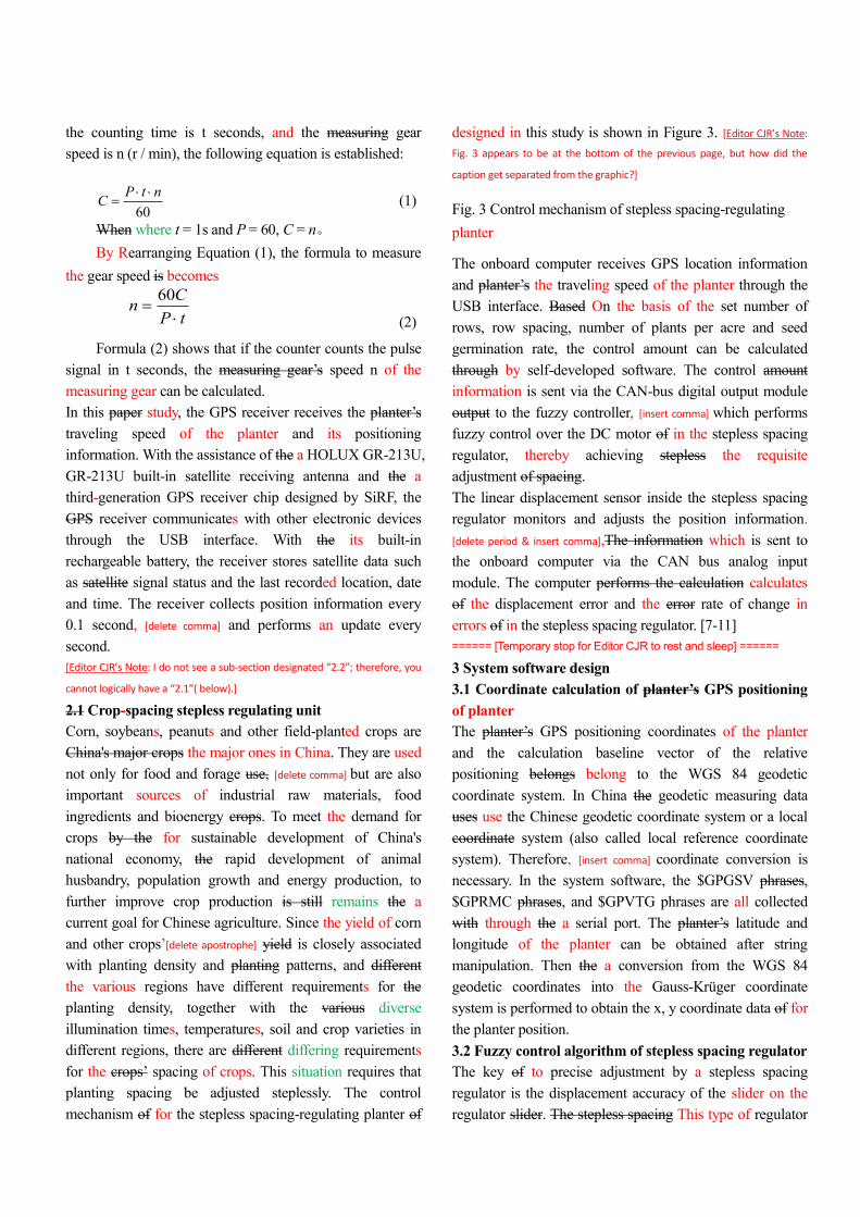
(4) The Direct reasoning of the fuzzy rules and
defuzzification
In the fuzzy logic theory, the inference of the fuzzy rules is
generally the a synthesis and calculation depending on the
fuzzy relation R. This way method has problems, [insert
comma] including a long computing time, a large amount of
computer memory, inconvenience in modifying the fuzzy
rules, etc. This system uses software real-time real-time
software online for reasoning, which uses a single-point
fuzzy set to make render the exact amount of the input
signal fuzzy, [delete comma] and applies the direct method to
reasoning about the fuzzy rules. Supposing Suppose that
there are two fuzzy control rules:
22222
11111
thenandif:
thenandif:
fuByAxR
fuByAxR
where Ai and Bi are the former fuzzy set, and fi is the
latter constant. Assume that the current input is x = x0, y =
y0. First obtain the degree of belonging of to which these
two inputs belong to the former conditions Ai (x0) and Bi
(y0). Then the former matching degree of the entire rule can
be calculated. [delete period & insert colon]:
)()( 01011 yBxA (3)
)()( 02022 yBxA
(4)
The overall reasoning result u0 is derived from the weighted
average of u1 and u2. [delete period & insert colon]:
21
22110
uuu (5)
For the control rules formed by m pieces of fuzzy
conditional phrases, the overall result u0 is
m
i
i
m
i
iiu
u
1
10
(6)
3.3 Software design and anti-jamming measures of the
computer control system
The system software uses the visual programming language
Delphi 7.0 to program in the Windows XP environment.
The HMI is the "simulate real" interface, which is shown in
Figure 7.

Figure 7 System interface of for planter’s working status
monitoring working status of planter
In Figure 7, left-click the computer-shaped icon, and the
screen will pop up sowing a parameter-setting window.
Left-click the icons to the right of each selection in the
setting window. [delete period & insert comma], and a parameter
selection list will appear. After left-clicking the appropriate
parameters have been left-clicked, the parameter selection
list disappears. When To setting set the right appropriate
seeding parameters, left-click on the icon “ 确 定
[determine]”, [delete comma & insert semi-colon]; and then, [insert
comma] the sowing parameter setting window will disappear.
Figure 8 Planter video-cam window
Left-click the camera icon, and the video window as
pictured in Figure 8 would will appear. The This window
would shows the a video image of planter’s the operational
status of the planter behind the tractor. In this way Thus,
[insert comma] the driver can know monitor the working status
of the planter from the window without turning head and
having to looking look back.
In Figure 7, a strip below the window there are displays of
the current date, time, planter running speed, heading
headed direction and the longitude/latitude data.
The system adopts The following anti-jamming measures
are adopted to guarantee the system’s work operational
reliability of the system functions in the system:
①The signal transmission uses the way of method for
electronic currency to avoid external interference.
②Data is transmitted using via CAN bus. The data
line uses a metal-shielded UTP, and the metal shield
grounded at the signal-receiving end is grounded.
③ An optocoupler is used to isolate the inside and
outside of the system in order to block the outside electrical
contact with the computer and to avoid external interference
from the outside world on the computer.
④An analog signal is acquired with the double-end
approach to improve the system's ability to resist common-
mode interference.
⑤ All the temporarily unused analog channels of the
multiplexer are shorted to an analog ground in order to
avoid crosstalk among analog the channels.
⑥Data acquisition is performed accomplished by
taking the average value of the repeated samples to
eliminate spikes and grid frequency interference.
⑦ A car-carried isolated power supply is used to
isolate the regulated power supply in order to prevent power
supply internal interference.
4 Experiments and Analysis
On May 23, 2011, after the experimental production of the
four-row planter was finished in the prototype modular
planting unit, field tests were conducted to examine the
planter’s mechanical the performance of the mechanical and
monitoring systems of the planter performance in the plots
of belonging to the Yiyuan Agricultural Machinery
Manufacturing Co. Company in Qingyun, Shandong
Province. Through the those tests, improvements are were
made on the ditching forms, metering device selection,
installation dimensions of the components, and the
detection effect of the sensors.
On June 16th, 2012, after the improvements on the
prototype was were finished, planting tests were run on the
Yiyuan Company’s plots of Yiyuan Agricultural Machinery

Manufacturing Co. in Qingyun, [delete comma] Shandong
Province and in the nearby smaller pieces of fields in
Dongxin Township after the wheat harvest.
Wheat stubble left in the test fields were in of different
various heights, different straw mulch, and varying
humidity had been left in the tested fields. Three types of
seeders were tested: (1) the passive- [delete hyphen] driving-
roller-driven mechanical-seeding type, (2) furrow-opening-
[delete hyphen] disc-rollover type, and (3) rotary-knife- [delete
hyphen] furrow-opening- [delete hyphen] rollover-seeding type.
The technical parameters tested and compared included
furrow-opening performance proficiency, planting precision,
stepless-spacing regulating regulation performance,
consistency of seeding depth, seed damage, soil-covering
performance proficiency, and monitoring system operations
working performance. According to the examination results
by from the Quality Supervision and Inspection Station of
Agricultural Machinery Products of Shandong Province, the
detection accuracy of for counting corn seed number was
91.4%; the seed-clog fault-alarm accuracy rate, [comma] was
96.0%; the fertilizer-clog fault-alarm accuracy, [comma]
was 95.5%. The results shows indicate that the entire
system was stable and reliable.
5 Conclusions Summary
(1) The distributive monitoring system of for monitoring
planting status developed in this study has the following
features: it
achieves bidirectional information transfer between
upper and lower PCs;
it can monitors spoon-plate speed, [delete comma] and
status of fertilizer tank and seed tanks;
it sends audible alarms;
it has real-time display of actual planting spaces;
it can realize enables real-time control and
regulating regulation of spacing; and
can show displays real-time video of the planter
during the planting process.
(2) The intelligent stepless spacing regulator developed in
the this study realizes satisfies the precision requirements of
for corn precise sowing and regulating on precise the
spacing of corn regulating. The device can achieve stepless
spacing regulating regulation of manually- and
electronically-controlled automatic seeding, in which the
transmission ratio ranges from 0.8 to 3.1 (corresponding to
the spacing 15 ~ 50cm). The regulator uses a micro-motor
to perform implement stepless CVT, which enables the
planter to change speed steplessly during work operation.

References [1]Huang Guangqun, Han Lujia, Liu Xian, and Yang Zengling. Establishment of an evaluation system
for integrated agricultural mechanization engineering technology [J]. Transactions of the Chinese
Society of Agricultural Engineering, 2012, (16):74-79.(in Chinese with English abstract) [Editor CJR’s
Note: Since this bibliographic information is a translation, I have improved the English therein. However, if it had already been published this way—with the errors-- I would not revise it. This comment also applies to other entries, below.]
[2]Huang Changyu. Brief Analysis into Yushu’s development of the modern agricultural machinery to
adapt to local characteristics [J]. Jilin Agriculture, 2010, (12): 225.
[3] Zhang Dongxing. The integration of agricultural machinery and agronomic technology to promote
the development of China's corn production mechanization [J]. Agricultural Technology and Equipment, 2011, (8): 202-204
[4] Organic integration of agricultural machinery and agronomics is the powerful engine to promote
China's agricultural modernization. Mechanization of Countryside and Pastoral Area. 2011,(3):1.
[5] Li Xiuhe, Chen Shaonian, Zhong Mingxing. Efficient cultivation techniques of potato, sweet corn,
long cowpea, and rice Interplanted rotation [J]. Modern Agricultural Science and Technology, 2006,
(5): 52
[6] Yao Zonglu, Li Hongwen, Gao Huanwen, et al. An experiment on a no-till wheat planter under the
best rows of the maize stubble in a double-cropping area [J]. Transactions of the Chinese Society for
Agricultural Machinery, 2007, 38(8):57-61. (in Chinese with English abstract)
[7] Chen Junda, Li Hongwen. Integrated research on conservation tillage equipment and technology
for dry-land corn production[J]. Transactions of the Chinese Society of Agricultural Engineering
(Transactions of the CSAE), 1998, 14(3):129-134. (in Chinese with English abstract)
[8] Hanna HM, Steward BL, Aldinger L. Soil loading effects of planter depth-gauge wheels on early
corn growth [J]. Applied Engineering in Agriculture, 2010, 26(4):551-556.
[9] Yang Zidong, Du Ruicheng, Liu Ningning, etc. Planter with power-assisted suffocating prevention
and integrated furrow opener [P]. China: 201210362643.1 2013-01-02
[10]NYT-1628-2008.Job quality of corn planter [S].
[11]He Jin, Li Hongwen, Wang Qingjie, el al. A Powered Hammering Blade No-till Wheat Seeder for
Permanent Raised Beds [J]. 2011,42 (10): 51-56. (in Chinese)
[12] Li Tai-we,Li Hong-wen,He Jin. Design of 2BMF-5 Type No-till Wheat Planter in Ridge-field.
Journal of Agricultural Mechanization Research.2008,(10):50-


