A data centre Standard for the Amsterdam Internet Exchange
18
A data centre Standard for the Amsterdam Internet Exchange A Standard defining the minimum acceptable, and also the desirable levels, of technical implementation, resilience of operation and business continuity management for data centres providing services to the Amsterdam Internet Exchange Westeinde 12 NL 1017 ZN Amsterdam Netherlands www.amsͲix.net
-
Upload
datacenters -
Category
Technology
-
view
246 -
download
2
Transcript of A data centre Standard for the Amsterdam Internet Exchange

A data centre Standard for the Amsterdam Internet Exchange
A Standard defining the minimum acceptable, and also the desirable levels, of technical implementation, resilience of operation and business continuity management for data centres providing services to the Amsterdam Internet Exchange
Westeinde 12NL �– 1017 ZN AmsterdamNetherlands
www.ams ix.net

Amendment record 1 Draft 12-3-09 BJE 2 First issue 2-4-09 BJE 3 Second issue 6-5-09 BJE 4 Third issue 15-5-09 BJE 5 Fourth issue 19-5-09 BJE 6 Fifth issue 19-10-09 BJE
Table of Contents
Contents1 Introduction ........................................................................................................................ 32 Minimal expectations of AMS IX ........................................................................................ 53 Technical design and implementation ............................................................................... 64 Operational Requirements ............................................................................................... 135 Business Continuity requirements ................................................................................... 14References ............................................................................................................................... 16Bibliography ............................................................................................................................. 16 Prepared by B J Elliott BSc, MBA, C.Eng, MIET, MCIBSE © Capitoline LLP 2009 Capitoline LLP Capitoline House 7 King Charles Terrace Sovereign Close London E1W 3HL www.capitoline.eu
Amsterdam Internet Exchange Doc ref CPTL 0908-09 Copyright licensed to AMS-IX AMS-09-001 Issue 005 19-10-09 BJE Page 2 of 18

1 Introduction
The successful and reliable provision of data centre services depends upon the following;
A well designed and constructed plant that takes into account appropriate Standards and bestpractice to achieve efficient and reliable operation
Management techniques that put in to place operating procedures and protocols that ensurethe continuing efficient and reliable operation of the data centre
Disaster recovery plans that have an established and rehearsed procedure for dealing with anyincident that impairs the operation of the data centre and puts in to place a recoveryprogramme
Technical Standards
Technical Standards give the best practice methods for designing and implementing the data centrefrom a physical, electrical and mechanical viewpoint. Some requirements covering health and safetyand energy management are covered by European Directives and national standards. Manytechnical standards exist that cover the myriad of engineering disciplines encountered in a datacentre but two documents in particular address the engineering aspects of data centre design andsubsequent resilience and redundancy of that design; these are:
ANSI/TIA 942:2005 Telecommunications Infrastructure Standards for Data Centers
and
Tier Classifications define site infrastructure performance. The Up Time Institute, 2008
The Up Time Institute�’s (TUI) document defines four �‘Tiers�’ of operation that describe the expecteddowntime per year from a data centre when certain design routes are taken. The TIA 942 standarddraws heavily upon the philosophy offered in the TUI document and offers more detail inengineering terms about what is required to achieve these levels.
One central plank of the philosophy is the adoption of the N, N+1 and 2N methodology. Briefly, Nmeans enough items to do the job at hand, N+1 means that each system has one redundantcomponent and 2N means that systems are completely replicated. Other variants may be 2N+1 forexample, meaning two independent systems where each system also has redundant components.Ultimately it is a risk versus cost strategy as more levels of redundancy and resilience will invariablycost more. Organisations are invited to consider the costs of downtime to their own business beforethey decide upon the strategy most appropriate to their business.
Both of the above standards are American. There are no directly equivalent European (CENELEC) orinternational standards (ISO/IEC). The methods described in the two American documents aremostly universal but for use in Europe the technical references contained in TIA 942 need to besubstituted for EU Directives and CENELEC standards wherever necessary.
The hierarchy and order of precedence of standards for the Netherlands is
Laws, Regulations and Statutory Instruments of The Netherlands Directives of the European Union Dutch national standards
Amsterdam Internet Exchange Doc ref CPTL 0908-09 Copyright licensed to AMS-IX AMS-09-001 Issue 005 19-10-09 BJE Page 3 of 18

CENELEC standards ISO/IEC standards Other relevant national standards, e.g. ANSI, TIA, BSI, VDE Industry best practice
Business Continuity standards
Building a data centre to the latest standards and incorporating the requisite availability/redundancytechniques is only the first step to successful long term operation. The next stage is managing thedata centre and being prepared for technical failures or any other event that impinges upon the datacentre operation. This area generally comes under the heading of Business Continuity Management,BCM. BCM standards can be generally aimed at all businesses and enterprises whereas some aremore focussed on Information and Communications Technology, ICT.
The following Standards have been identified which cover this area.
BS 7799 3:2006 Information security management systems. Guidelines for informationsecurity risk management
BS ISO/IEC 20000 1:2005 Information technology. Service management. Specification
BS ISO/IEC 27001:2005 Information technology. Security techniques. Information securitymanagement systems. Requirements
BS ISO/IEC 27002:2005, Information technology. Security techniques. Code of practice forinformation security management
BS 25999 1:2006 Business continuity management, Part 1: Code of practice
BS 25777:2008 Information and Communications Technology �– Continuity management,Code of Practice
BS ISO/IEC 17799:2005 Code of practice for information security management
ISO/PAS 22399:2007 Societal security Guideline for incident preparedness and operationalcontinuity management
NFPA 1600;2007 Standard on Disaster/Emergency Management and Business ContinuityPrograms
In addition we have ITIL. ITIL consists of a series of books giving guidance on the provision of qualityIT services, and on the accommodation and environmental facilities needed to support IT. ITIL hasbeen developed in recognition of organisations' growing dependency on IT and embodies bestpractices for IT Service Management.
We also have PRINCE. PRINCE2 is a generic, simple to follow project management method. It covershow to organise, manage and control projects. It is aimed at enabling you to successfully deliver theright products, on time and within budget. A Project manager can apply the principles of PRINCE2and the associated training to any type of project. It will help to manage risk, control quality andchange effectively.
Amsterdam Internet Exchange Doc ref CPTL 0908-09 Copyright licensed to AMS-IX AMS-09-001 Issue 005 19-10-09 BJE Page 4 of 18
A PRINCE2 project has the following characteristics:
A finite and defined life cycle Defined and measurable business products A corresponding set of activities to achieve the business products A defined amount of resources An organisation structure, with defined responsibilities, to manage the project.
In a survey by Continuity Central magazine of data centre managers in North America and Europe,BS 25999:2006 was the most widely used. In 2008 a companion standard was published, BS25777:2008 Information and Communications Technology �– Continuity management, Code ofPractice. It is the opinion of Capitoline LLP that, at the time of writing, BS 25777 is the mostappropriate document for use in Europe to describe best practice business continuity managementin the ICT environment.
2 Minimal expectations of AMS IX
2.1 Availability:
Maximum number of incidents; 1 outage in 5 years, maximum downtime of two hours Mean Time Between failures of not less than five years
2.2 Environmental conditions for network equipment
The temperature and humidity of the computer room must remain within the limits set by ASHRAEEnvironmental Guidelines for Datacom Equipment: 2008. This is more fully explained in Section 3.6 2.3 Fire suppression:
The facility must be protected by a high sensitivity automatic smoke detection system coupled withan automatic gaseous suppression system.
2.4 Maintenance regime:
Maintenance on critical items must take place at agreed times Maintenance windows will be 00h00 07h00 (GMT +1h) Maintenance will be announced to stakeholders in advance There will be no routine maintenance work on critical items outside of these time windows
2.5 Incident management
Incidents must be managed in a way that allows adequate response and analysis Outage announced within 5 min to AMS IX Network Operations Centre, NOC Outage announcements to be made through independent system that are independent from
power equipment production environment
2.6 Personnel
Amsterdam Internet Exchange Doc ref CPTL 0908-09 Copyright licensed to AMS-IX AMS-09-001 Issue 005 19-10-09 BJE Page 5 of 18

Only qualified personnel used for maintenance Communicate escalation procedures & contact information Regularly inform AMS IX on update escalation contact information Efficient site access for authorised AMS IX staff
The requirements will be met through three areas;
The technical design and installation of the data centre The management and maintenance procedures to operate the data centre A business continuity and disaster management programme The Minimum Requirements of AMS IX shall be proven by an audit of the data centre facility
by an external qualified auditor acceptable to both AMS IX and the operator of the datacentre
3 Technical design and implementation
3.1 Location
Minimum requirements3.1.1 The building must be in an area with flood protection
3.1.2 The building should be no closer than 0.10 km from a railroad or major interstatehighway
3.1.3 The building must be at least 500 m from a radar transmitter
3.1.4 The building must be at least 100m from a mobile telephone mast
3.1.5 The building must be at least 100m from any source of electrical interference
3.1.6 The building must have adequate access by road and nearby parking facilities
3.2 Architectural and building requirements
Minimum requirements3.2.1 Any computer room windows facing east, west or south must be covered to prevent
thermal solar gain.3.2.2 Computer room not to be located below plumbed areas such as rest rooms, janitor
closets, kitchens, laboratories and mechanical rooms unless a flood containmentsystem has been put in place.
3.2.3 The building must have a dedicated loading area to handle all anticipated deliveries ofsupplies and equipment.
3.2.4 The building materials must be non combustible e.g. brick, concrete, plasterboard etc.
3.2.5 The computer room height must allow 0.4 m above the equipment rack on a solidfloor and 0.4 m above and below a rack for a raised floor
3.2.6 All floors must be capable of supporting 750 kg equipment racks
3.2.7 If a raised floor is fitted then it must be at least 400 mm high with air flows notsubstantially blocked
Amsterdam Internet Exchange Doc ref CPTL 0908-09 Copyright licensed to AMS-IX AMS-09-001 Issue 005 19-10-09 BJE Page 6 of 18

3.3 Security and access control requirements
Minimum requirements3.3.1 Any windows at ground floor level, that allow direct access into the data centre, must
be barred3.3.2 Security staff per shift to be at least one person per 3000 m2of the data centre area
24 hours per day.3.3.3 Motion detector alarms in computer rooms, M&E plant rooms, telecommunication
entrance rooms and, office areas3.3.4 Doors into computer rooms to be controlled by pin, swipe card or biometric access
3.3.5 Main door into the data centre to be controlled by pin, swipe card or biometric access
3.3.6 Manned security counter with signing in and badge allocation to visitors
3.3.7 Digital CCTV monitoring and recording of all external doors to the computer rooms
3.3.8 No unauthorised persons must be able to enter the computer rooms, M&E plantrooms, telecommunication entrance rooms and office areas
3.4 Fire precautions, smoke detection and fire suppression
Minimum requirements3.4.1 Number and location of fire exits according to local codes
3.4.2 Fire exits to be unblocked, opening in the right direction and with 900 mm wideapproach routes
3.4.3 Emergency lighting to be in place according to local codes or EU Directives
3.4.4 Exit signage to be in place according to local codes or EU Directives
3.4.5 Manual call points must be fitted according to local codes
3.4.6 Walls and doors to the computer room, telecommunications rooms, M&E plantrooms and other critical areas to be fire rated to Dutch national standards
3.4.7 The computer room to be protected by two coincident (double knock) smokedetection systems. At least one system must be an aspirating smoke detector (ASD)monitoring return air flows. The second system must be another ASD device or acombination optical/ionisation detector
3.4.8 Other parts of the building must be monitored by an ASD or a combination optical/ionisation detector
3.4.9 All of the building�’s smoke detection systems must be integrated into one commonalarm
3.4.10 Setting off of the alarm must be transmitted to a third party monitoring agency or thefire brigade
3.4.11 A maintenance log covering all items related to fire detection and suppression mustbe available for inspection
3.4.12 Evidence of staff training in the event of a fire event must be available
3.4.13 Fire marshals who will oversee evacuation of the building and other agreed activitiesmust be identified for every shift
3.4.14 An algorithm showing the cause and effect status of all fire related equipment, e.g.HVAC, UPS, fire dampers, smoke detection, gas release etc., must be available forinspection and approval by AMS IX.
3.4.15 The computer room must be protected with a gaseous fire suppression system
3.4.16 The gas fire suppression system must be an EU approved clean agent with low ozonedepletion and global warming potential
Amsterdam Internet Exchange Doc ref CPTL 0908-09 Copyright licensed to AMS-IX AMS-09-001 Issue 005 19-10-09 BJE Page 7 of 18

3.4.17 The gas fire suppression system must only be activated by two separate andconcurring fire detection systems or by manual activation. The system must alsohave a manual override. The system must be left in automatic mode
3.4.18 Areas protected by the gas fire suppression system must be fitted with adequateoverpressure ventilation plates
3.4.19 A means of purging the area of gas after a discharge must be in place
3.4.20 Manual fire extinguishers must be placed at doorways or other relevant pointscontaining CO2 or other approved fire suppressant.
3.4.21 All fire related signage must be in place, e.g. gas suppression system warnings ondoors, �‘actions in the event of fire�’ notices etc
3.4.22 Every room protected by a gas suppression system must be pressure tested to ISO14520 and a certificate to that effect to be available proving the room has passed thepressure test within the last 12 months
3.4.23 All fire detection and suppression systems must be designed and installed byqualified personnel and designed to national or international standards, e.g. NFPA 75,BS 6266, VdS 2095 etc
3.4.24 If the computer room, telecommunications room or M&E plant rooms have asprinkler system then it must be of the pre action type
3.4.25 Adjoining rooms or buildings to the main data centre location should be protectedwith a sprinkler system. If they are not then the fire risk of the adjoining buildingmust be assessed and methods to limit fire spread described.
3.5 Provision of power supplies
Minimum requirements3.5.1 The site must be fed from a transformer substation dedicated to the data centre and
its associated facilities3.5.2 Transformers must be in a secured area
3.5.3 Power cables must enter the building and be terminated in a dedicated electricalswitch room containing all necessary switching and metering
3.5.4 The power available to the site from the mains utility must be at least 20% more thanthe peak projected load
3.5.5 At least two standby generators, in an N+1 configuration, are required to providepower in the event of a mains failure
3.5.6 The standby generator must be available with at least 24 hours of fuel
3.5.7 If more than one generator is available then an automatic synchronizing device mustbe fitted with a manual override operation possible
3.5.8 Operation of the generator will be by an automatic transfer switch that will detectmains failure
3.5.9 The generator will automatically switch off when mains power is restored
3.5.10 The generator will have manual controls but will be left set to the automatic settingunder normal circumstances
3.5.11 A maintenance and test regime will be in place and the system will have been testedwith a load bank and then with a �‘live�’ load
3.5.12 A connection will be made available so that an external generator can be pluggedinto the main switchboard
3.5.13 The generator and cabling will be in a secure location adjacent or within the datacentre
3.5.14 The power capacity of the generator will be at least 20% more than the peakprojected load
3.5.15 The ICT equipment will be protected by an Uninterruptible Power Supply, UPS, in anN+1 manner
Amsterdam Internet Exchange Doc ref CPTL 0908-09 Copyright licensed to AMS-IX AMS-09-001 Issue 005 19-10-09 BJE Page 8 of 18
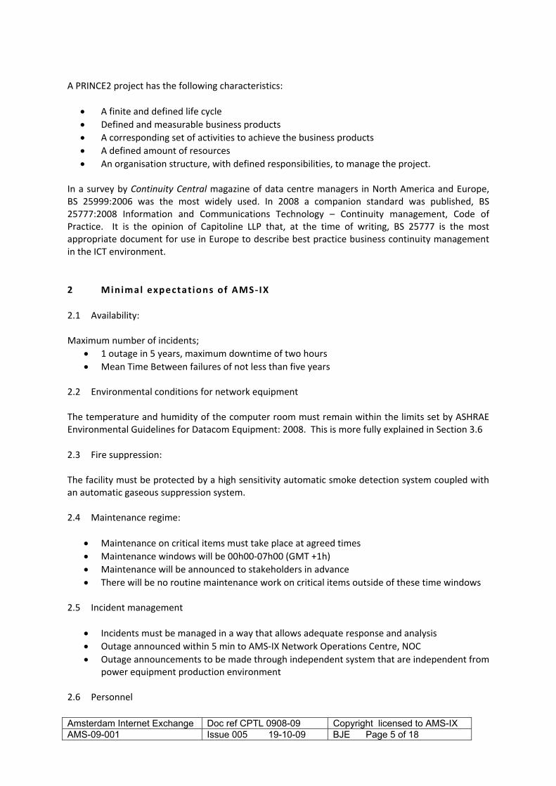
3.5.16 The energy storage mechanism of the UPS will be sufficient that there will beadequate time for the standby generator to start and come on line
3.5.17 Each UPS will have its own dedicated energy storage medium, e.g. battery string,kinetic energy system etc.
3.5.18 The UPS will be centralised
3.5.19 The capacity of the UPS will be greater than the peak projected load. The averagerunning load capacity will not be more than 80% of the UPS capability
3.5.20 The UPS will have a software based monitoring, reporting and alarm system
3.5.21 The UPS will be capable of an automatic and manual bypass onto raw mains feed inthe event of maintenance requirements or complete UPS failure
3.5.22 UPS unit connected in parallel will have been fully tested under load and will beguaranteed by the manufacturer for that configuration
3.5.23 The UPS will distribute power to the ICT equipment via Power Distribution Unit(PDU)switchgear
3.5.24 Two power cables will be available to each rack location fed from two separate PDUs
3.5.25 A rack designated as a communications rack will be able to be supplied with at leasttwo 32 amp single phase feeds
3.5.26 Racks requiring more power will be supplied with more 32 amp feeds but preferablywith a three phase distribution system
3.5.27 Three phase power distribution systems throughout the data centre will be evenlyloaded to within 5% of each other and this must be easily measurable at all significantpoints e.g. UPS output
3.5.28 Two power strips will be available in each rack each fed from a separate PDU. Eachpower strip must have a local current monitoring facility
3.5.29 The building will be protected with a lightning protection system
3.5.30 External plant such as generators and condensers will have all external metalworkearthed so that surge currents cannot enter the building
3.5.31 Incoming copper communications cables will be protected with surge suppressorsbefore they enter the computer room
3.5.32 The computer room will have an exposed copper main earth terminal that will be theearth reference point for the room
3.5.33 The following items will connected to the earthing system; all equipment racks, atleast every 6th leg of any floor pedestal arrangement, all metallic cable containment,all electrical switchgear, HVAC units and metallic ducting, all metallic pipes, theexposed structural steel of the building
3.5.34 If power is lost to a rack or racks then the system must be able to restartautomatically without causing circuit breakers to trip out due to high inrush currents.This may be achieved by using 'soft start' equipment, automatic sequential start upprocedures or by having sufficient overcapacity in the power supply train.
Amsterdam Internet Exchange Doc ref CPTL 0908-09 Copyright licensed to AMS-IX AMS-09-001 Issue 005 19-10-09 BJE Page 9 of 18

Note that transfer switchesand synchronisationdevices may be seen as asingle point of failure butthe probability of failure isregarded as sufficiently low
Figure 1Minimum acceptable power supply arrangement. Generally in an N+1 format
Amsterdam Internet Exchange Doc ref CPTL 0908-09 Copyright licensed to AMS-IX AMS-09-001 Issue 005 19-10-09 BJE Page 10 of 18

3.6 Provision of cooling and ventilation
Minimum requirements3.6.1 The computer room must maintain temperature and humidity control according to
the ASHRAE 2008 requirements listed below. Battery rooms must be limited to 250C.The system must maintain this capability at full load and with an externaltemperature of 360 C
3.6.2 HVAC equipment shall be connected to the mains input and backed up with a standbygenerator as described in section 3.5
3.6.3 HVAC equipment shall supply cooling capacity in an N+1 format
3.6.4 HVAC equipment shall be rated to at least 20% more capacity than the maximumexpected steady state load of the computer room even after one CRAC unit has failedor been turned off
3.6.5 Humidity control must be provided
3.6.6 A ventilation system must be in place to change the air in the computer, telecomsroom, plant room at approximately one air change per hour
3.6.7 All incoming air must be filtered according to EN 779 60% standard. Smoke detectorsmust be fitted to the incoming air, after filtration, that will shut off the air intakes ifsmoke is detected
3.6.8 A means of purging gas protected rooms must be in place for removal of firesuppression gas after a discharge event
ASHRAE 2008 computer room environmental requirements
Low end temperature 180 CHigh end temperature 270 CLow end moisture 5.50 C dew point (note, this may be taken as a minimum RH
of 35% for simple measuring)High end moisture 60% RH and 150 C dew point
In addition
Minimum cold aisle temperature 180 CMaximum cold aisle temperature 240 CMaximum hot aisle temperature 350 C
If there is no defined �‘hot aisle cold aisle�’ layout in place then measurements will be taken at the airinput and air exhaust sections of all appropriate racks.
3.7 Provision of Cabling and cable management
Minimum requirements3.7.1 A standards based structured cabling system is to be in place to provide connectivity
to every rack3.7.2 All interior cabling shall be of a low flammability type. Any new cabling must be
specified as low flammability and zero halogen type3.7.3 External cables, i.e. flammable construction, shall not be taken more than 5 m into
the building before they are terminated or enclosed in a non flammable conduitsystem
Amsterdam Internet Exchange Doc ref CPTL 0908-09 Copyright licensed to AMS-IX AMS-09-001 Issue 005 19-10-09 BJE Page 11 of 18

3.7.4 Every rack will have access to a cable containment system, above and or below it,that will allow cables to be properly managed between racks
3.7.5 Data and single phase power cables will be separated by at least 200 mm
3.7.6 Data and three phase power cables will be separated by at least 600 mm
3.7.7 No cable will be trapped in doors, laid out on the floor, strung between racks orforced into right angle bends
3.7.8 Every cable will have a unique identity label at both ends denoting origin, destinationand if necessary, owner
3.7.9 Every equipment rack will have a unique identity and if necessary, owner�’s label
3.7.10 There will be a separate telecommunications room or dedicated �‘comms�’ area in thecomputer room for connecting separate external telecommunications cables inputs.
3.7.11 Telecommunications rooms or areas, that contain active equipment, will provide; airconditioning and fire protection to the same standard as the computer room, changefrom external grade to internal grade cable, provide overvoltage protection on allcopper cables, provide a clear demarcation between ownership of cables andequipment
3.7.12 All cables passing through fire walls will be sealed against fire and smoke to nationalor EU regulations
3.7.13 All metallic cable containment items to be correctly earthed
3.7.14 Each equipment rack will provide adequate vertical and horizontal cablemanagement items to prevent patchcords from obscuring any item of equipment
3.8 Building Management Systems and monitoring
Minimum requirements3.8.1 The computer room will have one general temperature sensor and one general
humidity sensor for the room3.8.2 Telecommunications and plant rooms will have a general temperature and humidity
sensor3.8.3 There will be a water sensor under every raised floor, every CRAC unit and every
water cooled rack and also in every plant room3.8.4 Every sensor will be wired back to a dedicated BMS panel in one of the
telecommunications rooms3.8.5 A software based BMS will monitor
every temperature, humidity and water sensorthe status of the fire alarm panelthe status of the security/access control systemthe status of the incoming mains and automatic transfer switchthe status of the generatorsthe status of each UPS and CRAC unitthe status of any fire/smoke control or HVAC dampersits own status
3.8.6 This information will be displayed on a dedicated BMS terminal with graphicalinterface
3.8.7 The essential items of the BMS system will have a dedicated UPS supply with at leastone hour of battery time or with other power backup methods.
3.8.8 A management strategy will be in place that will describe the reaction to each alarm,who will respond and response outside of normal working hours
3.8.9 Essential alarms will connect via an external telecommunications circuit to an agreedlist of stakeholders
3.8.10 The BMS will store historical trends and generate incident logs and reports
Amsterdam Internet Exchange Doc ref CPTL 0908-09 Copyright licensed to AMS-IX AMS-09-001 Issue 005 19-10-09 BJE Page 12 of 18

3.8.11 The BMS will be fail safe in that if it should fail it will not affect the operation of anysystem that it purely monitors
4 Operat ional Requirements
Management techniques must be put in place that give operating procedures and protocols thatensure the continuing efficient and reliable operation of the data centre and timely communicationto all stakeholders.
4.1 Good work practices in the building
Minimum requirements4.1.1 The data centre will have one central manned pedestrian entrance and one general
loading bay area4.1.2 All equipment will be unpacked and assembled in a dedicated �‘build�’ area and not in
a live computer room4.1.3 There will be a dedicated control room or area. All control and monitoring functions
will be connected into and displayed in the control room
4.2 Operational Management Documentation required
Minimum requirements4.2.1 A general operations manual is required that brings together all the operating
requirements and settings of the data centre4.2.2 All major items of equipment, e.g. UPS, HVAC, generator etc shall be included in an
asset register which will include a settings and operational procedure to include Location Serial number Data of procurement Manufacturer contact details Maintenance/call out contact details Service history Dates of calibration if required Settings and set points to be observed e.g. RH and return temperature on CRACunits
4.2.3 A checklist is required of all items that need to be left in an �‘automatic�’ status andwhere these controls are located, e.g. fire control panel and gas suppression system,activation of standby generator etc
4.2.4 Site documentation information to include Building and floor plans Locations of racks and other major items of equipment Rack layout Logical and physical interconnectivity of equipment
4.2.5 A �‘call list�’ is to be available which will list all principle staff of the data centre, theirfunction and contact details plus any appropriate suppliers, maintenance companies
Amsterdam Internet Exchange Doc ref CPTL 0908-09 Copyright licensed to AMS-IX AMS-09-001 Issue 005 19-10-09 BJE Page 13 of 18
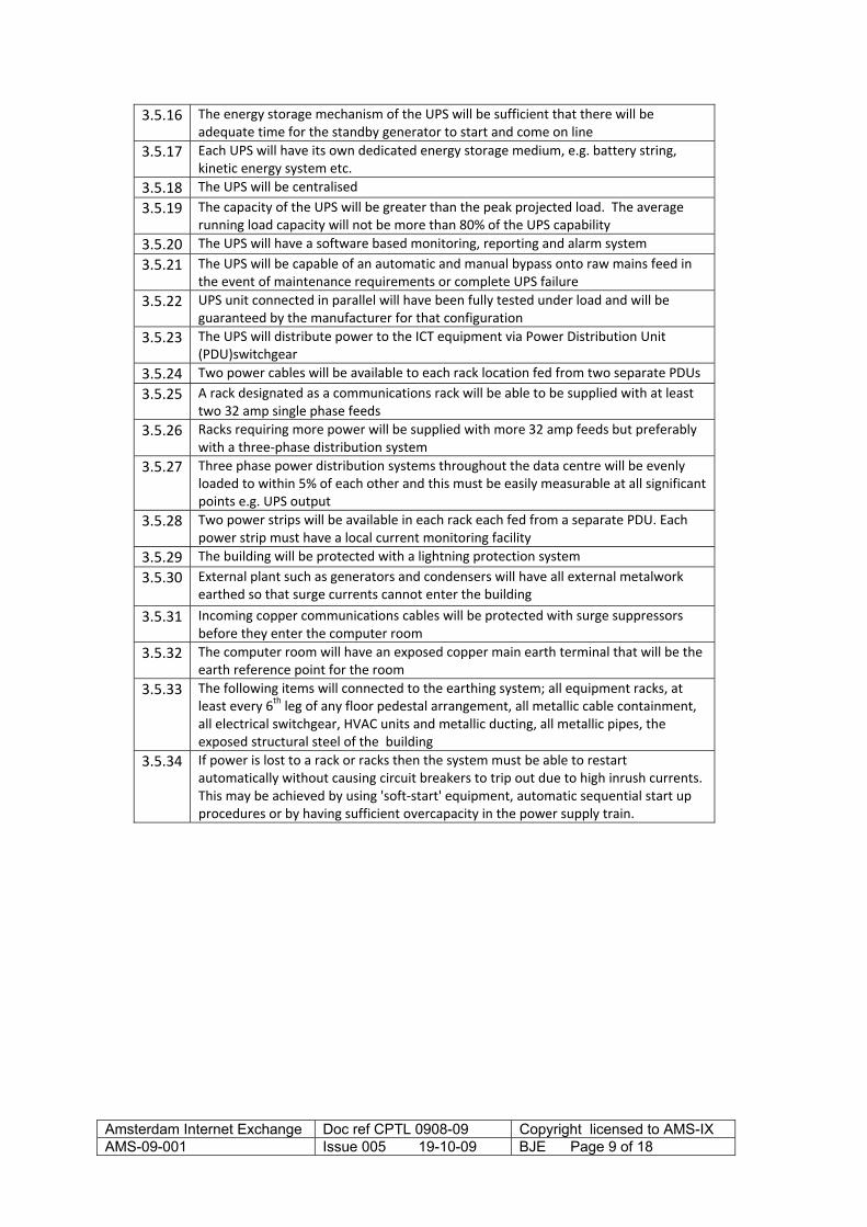
and emergency services4.2.6 The data centre will have a safety operations manual that will detail
Safe working at height Safe use of electricity Use of laser transmission equipment Lifting heavy loads Monitoring of noise in the workplace Use of barriers around work areas such as missing floor tiles etc
4.2.7 An algorithm chart is required that will detail the cause and effect of all related Fire detection Alarm states Activation of gas suppression Control of dampers Powering off of power supply equipment Powering off of HVAC units Restart procedures
4.2.8 A method statement is required detailing how visitors will be identified and escortedaround the site
4.2.9 A method statement is required detailing how external contractors may enter andwork on the site and how their work is monitored, controlled and recorded
4.2.10 An audit trail is required that demonstrates how changes to the design and fabric ofthe data centre are made. This could be by a Change Control Document and WorkOrder method
4.2.11 A written plan must be in place that details how all alarms states and system failureswill be handled by the data centre staff
4.3 Maintenance procedures
Minimum requirements4.3.1 Any internal staff involved in maintenance must be trained and qualified to do so. A
personal statement must demonstrate how this competence has been achieved e.g.,professional/trade qualifications, attendance at manufacturers�’ training courses etc
4.3.2 Any external contractor involved in maintenance must also be able to demonstratecompetence
4.3.3 All equipment requiring maintenance shall have a maintenance log detailing theequipment, maintenance dates, outcomes, contact details etc. See 4.2.2
4.3.4 Maintenance on critical items must take place at agreed times. These will be during07h00 12h00 (GMT +1h). Incident Management, i.e., to bring a component back intoproduction after a failure, should be done between 00h00 and 07h00Maintenancewill be pre announced to stakeholders at least one week in advance. There will be noroutine maintenance work on critical items outside of these time windows.
5 Business Continuity requirements
Recovery plans must be in place that has an established and rehearsed procedure for dealing withany incident that impairs the operation of the data centre and puts in to place a recoveryprogramme.
Amsterdam Internet Exchange Doc ref CPTL 0908-09 Copyright licensed to AMS-IX AMS-09-001 Issue 005 19-10-09 BJE Page 14 of 18

An ICT continuity programme must
Understand the threats to, and vulnerabilities of, ICT services Identify the potential impacts of disruption to ICT services Provide collaboration between data centre staff, internal and external service providers and
stakeholders Demonstrate competence by credible responses through exercising ICT continuity plans and
test ICT continuity arrangements
The data centre must be able to
Protect the ICT environment through resilient design and best practice engineering Detect incidents at the earliest opportunity React to an incident in an appropriate manner Recover the data processing and communications systems in a prioritised manner Operate in a disaster recovery mode until normal operations are possible Return to a normal business position
5.1 Incident handling and disaster recovery
Minimum requirements5.1.1 The data centre must have a risk assessment analysis that details risks, the impact of
these risk and the strategy to obviate these risks, e.g. Site: fire, flooding Operations: power supply failure Personnel: major epidemic etc Communications: main cable damage
5.1.2 All critical systems such as UPS status, fire conditions etc, must be automaticallymonitored. These are detailed in section 3.8
5.1.3 Any critical failure or loss of service must be communicated to AMS IX by telephonewithin five minutes
5.1.4 Any critical failure or loss of service must be automatically communicated to allrelevant personnel, management and other stakeholders within five minutes
5.1.5 The method of communication to external agencies and stakeholders must beindependent of the same critical facilities that have failed e.g. essential monitoringand communications equipment must be powered by an independent battery backedsupply
5.1.6 A written plan must be in place that details how all alarms states and system failureswill be handled by the data centre staff
5.1.7 All major incidents will be subject to a management review that will detail What the incident was Where it happened When it happened What was the impact on service provision How was it dealt with What changes can be made to prevent a similar incident happening again
5.1.8 A statement is required that will detail the impact of a sudden and complete loss ofpower on the ICT equipment and how a restart will be managed
Amsterdam Internet Exchange Doc ref CPTL 0908-09 Copyright licensed to AMS-IX AMS-09-001 Issue 005 19-10-09 BJE Page 15 of 18

5.1.9 A �‘call list�’ is to be available which will list all principle staff of the data centre, theirfunction and contact details plus any appropriate suppliers, maintenance companiesand emergency services. Contact details must also include �‘out of hours�’ contactdetails and define responsibilities of all the parties.
5.1.10 The effects of power cuts must be simulated to prove the operation of UPS andgenerator start up routines. These simulations must be treated as maintenanceepisodes and take place and be communicated as 4.3.3
References
ANSI/TIA 942:2005 Telecommunications Infrastructure Standards for Data CentersASHRAE 2008 computer room environmental requirementsTier Classifications define site infrastructure performance. The Up Time Institute, 2008BS 6266:2002 Code of practice for fire protection for electronic equipment installationsEN 779:2002 Particulate air filters for general ventilation. Determination of the filtrationperformanceEN 50173 5: Information technology: Generic Cabling for Data CentresISO 14520 1:2006 Gaseous fire extinguishing systems. Physical properties and system design.General requirementsNFPA 75: Standard for the Protection of Information Technology Equipment, 2009 EditionVdS 2095:2005 02 VdS guidelines for automatic fire detection and fire alarm systems Planning andinstallation
Bibliography
Access for the disabled
Council Directive 2000/78/EC of 27 November 2000 establishing a general framework for equaltreatment in employment and occupationBS 8300:2008 Design of buildings and their approaches to meet the needs of disabled people �— Codeof practice
Business Continuity
BS 7799 3:2006 Information security management systems. Guidelines for information security riskmanagementBS ISO/IEC 20000 1:2005 Information technology. Service management. SpecificationBS ISO/IEC 27001:2005 Information technology. Security techniques. Information securitymanagement systems. RequirementsBS ISO/IEC 27002:2005, Information technology. Security techniques. Code of practice forinformation security managementBS 25999 1:2006 Business continuity management, Part 1: Code of practiceBS 25777:2008 Information and Communications Technology �– Continuity management, Code ofPractice
Amsterdam Internet Exchange Doc ref CPTL 0908-09 Copyright licensed to AMS-IX AMS-09-001 Issue 005 19-10-09 BJE Page 16 of 18

BS ISO/IEC 17799:2005 Code of practice for information security managementISO/PAS 22399:2007 Societal security Guideline for incident preparedness and operationalcontinuity managementNFPA 1600;2007 Standard on Disaster/Emergency Management and Business Continuity Programs
Designs to minimize fire risk
British Building Regulations: 2000 Part B, Fire stoppingThe Construction Products Directive (Council Directive 89/106/EEC)BS 5839 6:2004 Fire detection and fire alarm systems for buildings. Code of practice for the design,installation and maintenance of fire detection and fire alarm systems in dwellingsBS 6266:2002 Code of practice for fire protection for electronic equipment installationsISO 14520 1:2006 Gaseous fire extinguishing systems. Physical properties and system design.General requirementsBS 7273 1:2006 Code of practice for the operation of fire protection measures. Electrical actuationof gaseous total flooding extinguishing systemsEN 54 20:2006 Fire detection and fire alarm systems. Aspirating smoke detectorsEN 779:2002 Particulate air filters for general ventilation. Determination of the filtrationperformanceBFPSA Code of Practice for Design, Installation, Commissioning & Maintenance of Aspirating SmokeDetector (ASD) Systems 2005BFPSA Guidance on EC Regulation No 842/2006 on Certain FluorinatedGreenhouse Gases 2006Regulation (EC) No 842/2006 of the European Parliament and of the Council of 17 May 2006 oncertain fluorinated greenhouse gasesNFPA 72: NATIONAL FIRE ALARM CODE:2007NFPA 75: Standard for the Protection of Information Technology Equipment, 2009 Edition
Electrical Safety
BS 7671 (IEE 17th Edition) �– Requirements For Electrical InstallationsBS 6701 �–Telecommunications Equipment and cablingEN 50310 �– Bonding & Earthing in Buildings With IT equipmentEN 60950 1:2002, Information technology equipment Safety ~ General requirementsNEN 1010:2007 Dé norm voor laagspanningsinstallaties
Emergency Lighting and signage
BS 5266 : Part 1 : 1999 Code of Practice for Emergency LightingBS 5499 5:2002 Graphical symbols and signs ~ Safety signs, including fire safety signs Signs withspecific safety meaningsStatutory Instrument 2005 No. 1541 The Regulatory Reform (Fire Safety) Order 2005
Energy consumption and optimisation
EU Energy performance of Buildings Directive 2002/91/ECEU Energy Services Directive 2006/32/ECEnergy savings at Data Hotels, The Environmental and building department of the Municipality ofAmsterdam, ECN, April 2008
Amsterdam Internet Exchange Doc ref CPTL 0908-09 Copyright licensed to AMS-IX AMS-09-001 Issue 005 19-10-09 BJE Page 17 of 18

Amsterdam Internet Exchange Doc ref CPTL 0908-09 Copyright licensed to AMS-IX AMS-09-001 Issue 005 19-10-09 BJE Page 18 of 18
EU Code of Conduct on Data Centres Energy Efficiency Version 1.0 EUROPEAN COMMISSIONDIRECTORATE GENERAL JRC JOINT RESEARCH CENTRE Institute for Energy Renewable Energies Unit,October 2008
Health and safety
The Construction (Design and Management) Regulations 2007Workplace (Health, Safety and Welfare) Regulations 1992ANSI Z136.2 Safe Use of Lasers in Optical Fiber Communication Systems Utilizing Laser Diode andLED SourcesIEC 60825 2. Safety of Laser Products Part 2: Safety of optical fibre communication systems (OFCS).
HVAC
ASHRAE Thermal Guidelines for Data Processing Environments 2004CIBSE Guide B. Heating, ventilation, air conditioning and refrigerationThe Building Regulations Approved Document F VentilationTIA 942 Telecommunications Infrastructure Standard for Data CentersVDI 2054 Air conditioning for computer areas
Raised Access Floors
EN 12825:2001 Raised access floorsProperty Services Agency (PSA) Method of Building Performance Specification 'Platform Floors(Raised Access Floors)', MOB PF2 PSRIBA NBS K41 Raised access floors
System Design
EN 50173 2: IT Generic IT Cabling For Customers PremisesEN 50172 3: IT Generic Cabling for Industrial PremisesEN 50173 4: IT Generic Cabling for HomesEN 50173 5: IT Generic Cabling for Data CentresISO 11801:2001 IT Generic CablingTIA 942 Telecommunications Infrastructure Standard for Data Centers
System Installation and quality assurance
EN 50174 1 (2000) Information technology �– cabling installation �– Part 1: Specification and qualityassuranceEN 50174 2 (2000) Information technology �– Cabling installation �– Part 2: Installation and planningpractices inside buildings,ISO/IEC TR 14763 2 �–Information technology �– Implementation and operation of customer premises�– part 2: Planning and installation
System Test
EN 50346:2002 Information technology Cabling installation Testing of installed cablingIEC 61935 1 Generic cabling systems �– Specification for the testing of balanced communicationcabling in accordance with ISO/IEC 11801 �– Part 1: Installed cabling


![[Internet]. Amsterdam: Elsevier; 2012 [cited 2013 Dec 11].](https://static.fdocuments.us/doc/165x107/589aeae61a28abeb468bc2a0/internet-amsterdam-elsevier-2012-cited-2013-dec-11.jpg)