I-N-D-E-P-E-N-D-E-N-T variables, dependent variables, and constants

51076092972359 Instruction rev 0.0 03/25/2019 CAD
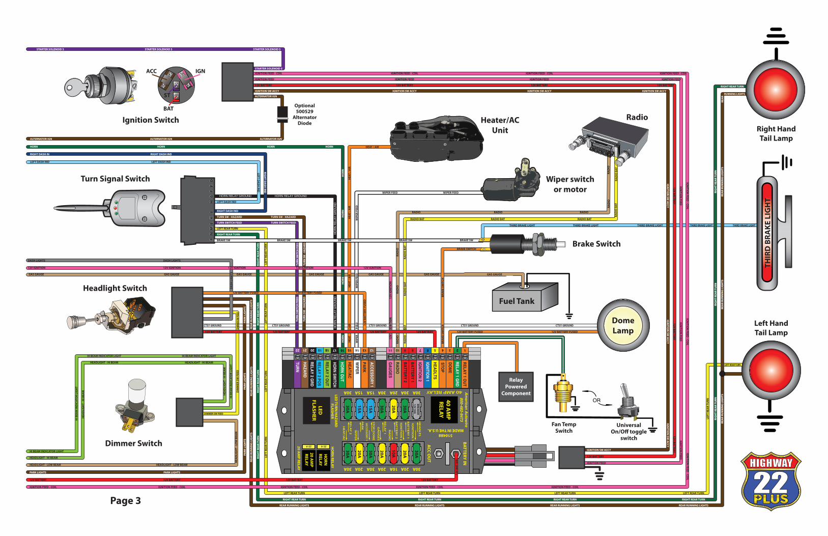
Full Vehicle Schematic
This wiring kit is designed for ease of installation. Please read the guidelines below, BEFORE STARTING YOUR INSTALLATION, to guarantee a successful job!
STEP 1: DISCONNECT YOUR BATTERYDisconnect the battery before installing the wiring kit to prevent any accidental shorting caused by loose bare wire ends.
STEP 2: MOUNT YOUR PANELIt is recommended that you mount your panel under the dash, in the kick panel, or under the front seat. The fuse panel can be found in bag 510488.
STEP 3: START INSTALLING KIT
This kit is broken down into individual steps that are identi�ed by a letter printed on the instruction sheets visible through each bag. These letters are the order of operation for installing your kit.Start with the bag letter "A", then "B", etc. The order of installation is shown below.
A 510494 Ignition Switch and Starter Wiring KitB 510493 Alternator Connection KitC 510490 Headlight Switch KitD 510489 Steering Column / Turn Signal Connection KitE 510491 Gauge Connection Kit (Sending Unit Side)F 510492 Accessory Connection Kit
STEP 4: RECONNECT YOUR BATTERY
When you have completed the installation and are ready to reconnect the battery, make sure that the following electrical system grounds are in place:
A. Battery is grounded to the engine block.B. Battery is grounded to the frame.C. Engine block is grounded to the frame.D. Body is grounded to the frame.
STEP 5: CHECK ALL ELECTRICAL FUNCTIONS
Any non-functioning items should be checked for proper installation. Any problems with your wiring and electrical circuit functions should be addressed with American Autowire Systems, Inc. as soon as possible to avoid any warranty problems.
If you have any questions concerning this or any of our products, please feel free to call us at 1-800-482-WIRE.
"AMERICAN AUTOWIRE MAKES WIRING THAT EASY!”
OPTIONAL ACCESSORY KITS
Battery cables See page 4Brake Switch p/n 500097 Button type, 2 blade contact to operate brake lightsBrake Switch p/n 500145 Button type, 4 blade contact to operate brake lights and cruiseBrake Switch p/n 500098 Lever type, water resistantBrake Switch p/n 500240 Adjustable lever design, water resistantCourtesy Light Kit p/n 500081 Under dash lighting harness complete with lamp socketsUniversal 40 amp Relay Kit p/n 500479 Complete kit wired with relay and fuse.Fan Temperature switch p/n 500493 On at 210 deg, o� at 195 deg. Used with 500067 Fan relay kit.Fan Temperature switch p/n 500491 On at 195 deg, o� at 180 deg. Used with 500067 Fan relay kit. Fan Temperature switch p/n 500492 On at 180 deg, o� at 160 deg. Used with 500067 Fan relay kit.Grounding kit - Full vehicle p/n 500717 Complete vehicle grounding system customizable to any vehicle.Grounding / Splice kit p/n 500544 Complete 12 to 1 splice kit for grounding or power connection.Heater Switch p/n 500144 3 position heater switchL.E.D. indicator lights Amber, blue, green, and red in both 5/32' and 1/4" sizes.Master Disconnect switch p/n 500003 Master battery disconnectUniversal Relay Kit - Waterproof p/n 500093 Use for any heavy duty application requiring a relay.Wiper Switch p/n 500146 Two speed switch for wiper.Ground Strap p/n 500350 12” with 3/8” mounting holesGround Strap p/n 500656 18” with 3/8” mounting holes11 Volt Warning Module p/n 510287 For use with one wire alternators using an indicator light.
INSTALLATION INSTRUCTIONS
150 Heller Place Bellmawr, NJ 08031 856-933-0801
THIS KIT DOES NOT SUPPORT STOCK (ORIGINAL) GENERATORS. THE DESIGN OF THE KIT IS DESIGNED TO SUPPLY MORE POWER THAN THE GENERATOR IS ABLE TO SUPPLY.
VE T E R A N O W
NE
D
M
A D E I N U S A
150 Heller Place Bellmawr, NJ 08031 856-933-0801
Page 1

LEFT
DA
SH IN
D
Right HandHeadlight
TemperatureSwitch
MEGA175A
LITTLEFUSE
MEGA175A
LITTLEFUSE
10SI Alternator
R S
Starter
MEGA-Fuse Assembly
Oil SenderHEI Distributor
Optional NeutralSafety Switch
Right HandPark Lamp
Left HandPark Lamp
Left HandHeadlight
GaugeCluster
Positive Battery Cable (not included)
Horns
COIL--> TACH COIL--> TACHCOIL--> TACH
COIL
-->
TACH
COIL--> TACH
COIL
-->
TACH
COIL--> TA
CHCO
IL--> TACH
COIL--> TACH GROUND GROUND
GRO
UN
DG
ROU
ND
GROUND
GRO
UN
D
12V IGNITION 12V IGNITION 12V IGNITION
OIL
PRE
SSU
RE S
END
ER
OIL PRESSURE SENDER
OIL
PRE
SSU
RE S
END
ER
O
IL P
RESS
URE
SEN
DER
WAT
ER T
EMPE
RATU
RE S
END
ER
WATER TEMPERATURE SENDER
WAT
ER T
EMPE
RATU
RE S
END
ER
GAS GAUGE GAS GAUGE GAS GAUGE
LEFT DASH IND
LEFT
DA
SH IN
DLE
FT D
ASH
IND
RIG
HT
DAS
H IN
DRI
GH
T D
ASH
IND
RIGHT DASH IND
HI BEAM INDICATOR LIGHT
HI B
EAM
IND
ICAT
OR
LIG
HT
DASH LIGHTS DASH LIGHTS DASH LIGHTS
HI B
EAM
IND
ICAT
OR
LIG
HT
HI BEAM INDICATOR LIGHT
HORNHORNHORNHORNHORNHORN
HO
RN
HORN
STARTER SOLENOID SSTARTER SOLENOID S
IGNITION FEED - COILIGNITION FEED - COILIGNITION FEED - COILIGNITION FEED - COILIGNITION FEED - COIL
IGN
ITIO
N F
EED
- CO
ILIG
NIT
ION
FEE
D -
COIL
IGN
ITIO
N F
EED
- CO
IL
IGNITION FEED - COIL
LEFT DASH IND
RIGHT DASH IND
LEFT DASH IND
RIGHT DASH IN
LEFT FRONT TURN
RIGHT FRONT TURN
LEFT FRONT TURN
RIGHT FRONT TURN
LEFT FRONT TURN
RIGHT FRONT TURN
LEFT FRONT TURN
RIGHT FRONT TURN
LEFT FRONT TURN
LEFT
FRO
NT
TURN
LEFT
FRO
NT
TURN
LEFT
FRO
NT
TURN
RIGHT FRONT TURN
RIG
HT
DA
SH IN
D
HEADLIGHT - LOW BEAM
HEADLIGHT - HI BEAM
PARK LIGHTS
HEADLIGHT - LOW BEAM
HEADLIGHT - HI BEAM
PARK LIGHTS
HEADLIGHT - LOW BEAM
HEADLIGHT - HI BEAM
PARK LIGHTS
HEADLIGHT - LOW BEAM
HEADLIGHT - HI BEAM
PARK LIGHTS
HEADLIGHT - LOW BEAM
HEADLIGHT - HI BEAM
PARK LIGHTS
HEADLIGHT - LOW BEAM
HEADLIGHT - HI BEAM
HEA
DLI
GH
T - L
OW
BEA
M
HEA
DLI
GH
T - H
I BEA
M
HEA
DLI
GH
T - L
OW
BEA
M
HEA
DLI
GH
T - H
I BEA
M
HEA
DLI
GH
T - L
OW
BEA
M
HEA
DLI
GH
T - H
I BEA
M
PARK
LIG
HTS
PARK
LIG
HTS
PARK
LIG
HTS
PARK
LIG
HTS
12V BATTERY
12V
BAT
TERY
12V
BAT
TERY
12V
BAT
TERY
12V
BAT
TERY
12V
BAT
TERY
12V
BAT
TERY
12V BATTERY 12V BATTERY 12V BATTERY12V BATTERY
ALTERNATOR IGNALTERNATOR IGNALTERNATOR IGNALTERNATOR IGNALTERNATOR IGNALTERNATOR IGN
ALT
ERN
ATO
R IG
N
Page 2
Fuel Tank
Right HandTail Lamp
PN
ML
KJ
HG
FE
DP
NM
LK
JH
GF
ED
Ignition Switch
Turn Signal Switch
Headlight Switch
Fan TempSwitch
OR
UniversalOn/O� toggle
switch
Wiper switchor motor
ACC
BAT
ST
IGN
Brake Switch
Dimmer Switch
Optional500529
AlternatorDiode
DomeLamp
Left HandTail Lamp
RelayPowered
Component
THIR
D B
RAKE
LIG
HT
RadioHeater/ACUnit
12V IGNITION 12V IGNITION 12V IGNITION 12V IGNITION 12V IGNITION
12V
IGN
ITIO
N12
V
IG
NIT
ION
GAS GAUGE GAS GAUGE GAS GAUGE GAS GAUGE GAS GAUGE GAS GAUGE GAS GAUGE
DASH LIGHTS DASH LIGHTS
DA
SH L
IGH
TS
HI BEAM INDICATOR LIGHT
HI B
EAM
IND
ICAT
OR
LIG
HT
HI BEAM INDICATOR LIGHT HI BEAM INDICATOR LIGHT
HI B
EAM
IND
ICAT
OR
LIG
HT
RAD
IO
HO
RN
WIP
ER
F
EED
WIP
ER F
EED
HEA
T
/
AIR
HEA
T / A
IRH
EAT
/ AIR
HEA
T / A
IR
HEAT / AIR
WIP
ER F
EED
WIPER FEED WIPER FEED
HO
RNH
ORN
HO
RN
HORNHORNHORNHORN
RAD
IORA
DIO
RADIO RADIO RADIO
RAD
IORA
DIO
RAD
IO B
ATRA
DIO
BAT
RADIO BATRADIO BATRADIO BAT
RAD
IO B
ATRA
DIO
BAT
RAD
IO
B
AT
STARTER SOLENOID S
STARTER SOLENOID SSTARTER SOLENOID SSTARTER SOLENOID S
IGNITION FEED - COIL
IGNITION FEED IGNITION FEED IGNITION FEED IGNITION FEED
IGN
ITION
FEEDIG
NITIO
N FEED
IGN
ITION
FEED
IGNITION FEED
IGNITION FEED - COIL IGNITION FEED - COIL IGNITION FEED - COIL
IGN
ITION
FEED - CO
ILIG
NITIO
N FEED
- COIL
IGN
ITION
FEED - CO
IL
IGNITION FEED - COILIGNITION FEED - COILIGNITION FEED - COILIGNITION FEED - COILIGNITION FEED - COIL
12V BATTERY 12V BATTERY 12V BATTERY 12V BATTERY
12V BATTERY
12V BATTERY
12V BATTERY
12V BATTERY
IGNITION SW ACCY IGNITION SW ACCY IGNITION SW ACCY IGNITION SW ACCY
IGN
ITION
SW A
CCYIG
NITIO
N SW
ACCY
IGN
ITION
SW A
CCY
IGNITION SW ACCY
LEFT DASH IND
LEFT DA
SH IN
D
RIGHT DASH IND
RIGH
T DA
SH IN
D
LEFT DASH IND
RIGHT DASH IND
LEFT DASH IND
RIGHT DASH IN
TURN SW - HAZARD
TURN SWITCH FEED
LEFT REAR TURN
RIGHT REAR TURN
LEFT
REA
R TU
RN
RIG
HT
REA
R TU
RN
LEFT
REA
R TU
RN
RIG
HT
REA
R TU
RN
LEFT
REA
R TU
RN
RIG
HT
REA
R TU
RN
LEFT
REA
R TU
RN
RIG
HT
REA
R TU
RN
BRAKE SW
TURN SW - HAZARD
TURN SWITCH FEED
TURN
SW
- H
AZA
RD
TURN
SW
ITCH
FEE
D
TURN
SW
- H
AZAR
D
TURN
SW
ITCH
FEE
D
BRAKE SW BRAKE SW BRAKE SW BRAKE SW
LEFT REAR TURN
RIGHT REAR TURN
LEFT REAR TURN
RIGHT REAR TURN
LEFT REAR TURN
RIGHT REAR TURN
LEFT REAR TURN
RIGHT REAR TURN
LEFT
REA
R TU
RN
RIG
HT
REA
R TU
RNRI
GH
T RE
AR
TURN
RIG
HT
REA
R TU
RN
RIGHT REAR TURN
LEFT REAR TURN
THIRD BRAKE LIGHT THIRD BRAKE LIGHT THIRD BRAKE LIGHT THIRD BRAKE LIGHT THIRD BRAKE LIGHT
BRAKE SWITCH
BRA
KE S
WIT
CHBR
AKE
SW
ITCHCTSY GROUND CTSY GROUND CTSY GROUND CTSY GROUND CTSY GROUND
12V BATTERY FUSED12V BATTERY FUSED12V BATTERY 12V BATTERY 12V BATTERY 12V BATTERY
DIM
MER
SW FE
EDD
IMM
ER S
W F
EED
DIMMER SW FEED
HEA
DLI
GH
T - L
OW
BEA
M
HEADLIGHT - LOW BEAMHEADLIGHT - LOW BEAM
HEA
DLI
GH
T - H
I BEA
M
HEADLIGHT - HI BEAMHEADLIGHT - HI BEAM
HEA
DLI
GH
T - H
I BEA
M
HEADLIGHT - HI BEAM
PARK LIGHTS PARK LIGHTS
PARK
LIG
HTS
PARK
LIG
HTS
PARK
LIG
HTS
REA
R RU
NN
ING
LIG
HTS
REA
R RU
NN
ING
LIG
HTS
REA
R RU
NN
ING
LIG
HTS
REAR RUNNING LIGHTS REAR RUNNING LIGHTS REAR RUNNING LIGHTS REAR RUNNING LIGHTS
REA
R RU
NN
ING
LIG
HTS
REA
R RU
NN
ING
LIG
HTS
REA
R RU
NN
ING
LIG
HTS
RUNNING LIGHTS
T UR
N
SW R
ELA Y
HAZ
A
20 A20 A
1213141517 161820 1922 21 123456710 811 9
RELAY 1 OUT
RELAY 1 GRDDOM
E
STOP
IGNITION 1HEADLTS
IGNITION 2
BATTERY 1
RADIO
BATTERY 2
GAUGES
ACCESSORY 1
PARKW
IPER
HEAT/AC
HORN OUT
HORN SWITCH
RELAY 2 OUT
RELAY 2 POSRELAY 2 GRDHAZARD
TURN
BREAKER
12V 30A
30A
30A 30A30A 20A15A30A 15A
20A 30A20A 10A20A30A 30A
20A
30A
15A
15A
30A
20A
30A
10A
20A
30A
20A
30A
Am
erican Autow
ire800-482-9473
BATTERY IN
ACC O
UT
HO
RN RELAY
20 AM
P RELAY
LED TU
RN/H
AZA
RD
FLASH
ER
HO
RNRELAY
20 AM
PRELAY
LEDFLA
SHER
40 AM
PRELAY
510488MADE IN THE U.S.A.
40 AMP RELAY
BA
TT
ER
Y 1
IGN
ITIO
N 2
HE
AD
LTS
IGN
ITIO
N 1
BA
TT
ER
Y 2
RA
DIO
RE
LA
Y 1
GA
UG
ES
ST
OP
/DO
ME
ACC
ESSORY
1P
AR
K
WIP
ER
RE
LA
Y 2
HE
AT
/AC
12V
BAT
TERY
12V BATTERY 12V BATTERY12V BATTERY12V BATTERY
ALTERNATOR IGN
ALTERNATOR IGNALTERNATOR IGNALTERNATOR IGN
REA
R
Page 3
12V BATTERY FUSED 12V BATTERY FUSED
12V
BAT
TERY
FU
SED
HORN RELAY GROUND HORN RELAY GROUND
HO
RN
REL
AY G
RO
UN
DH
OR
N R
ELAY
GR
OU
ND

Additional Accessories
500350 - 12”500656 - 18”
Ground Straps
Medium duty ground straps are 100% tinned copper. Both sizes have a 3/8” hole on both ends.
500097Brake Switch
Pedal mounted brake switch.Universal �t. Comes complete
with connectors and terminals.Many di�erent styles available
in our catalog.
510643Terminal Kit
We’ve included the most common terminals and connectors that will help you with troubleshooting, repairing, or replacing connections. All contents are compartmentalized in a durable case with a heavy duty latching closure. The inside of the lid has a diagram detailing the contents by image and description.
510451Weather Pack Kit
This 429 piece weather pack kit provides you with plenty of connection options that will help you with troubleshooting, repairing, or replacing connections. All contents are compartmentalized in a durable case with a heavy duty latching closure. The inside of the lid has a diagram detailing the contents by image and description.
500081Courtesy Kit
For connecting two under dash lamps to headlight switch & door switches. Has sockets w/ mounting brackets & terminals for bullet, blade, or screw type door switches.
510587Wire Crimpers
The single crimper is used for wire sizes ranging from 14 to 20 gauge, and the double crimper is used for sizes from 10 to 18 gauge, or terminals receiving a two wire connection.
Page 4
510451Weather Pack Kit
500717All Copper Grounding Kit
Copper Grounding Kit eliminates the frame rail as a conductor a by using three grounding boxes connected by 6 gauge copper cables. The ground "loop" attaches to your existing negative battery cable to make for a solid, continuous connection. Includes 20 coils of pre-labeled wire, terminal lugs and a 6 gauge crimping tool.
500834Remote Master Disconnect
SwitchControl your battery disconnect with a small remote mounted switch. Can be used with remote control modules. SPST latching solenoid with two 5/16” studs Rated at 110 amps continuous.
510287Volt Module
The 11 volt module can be used to trigger an in-dash warning light when charging system voltage drops below 11 volts. This makes it the perfect solution to control a dash indicator light when installing a one-wire alternator, or simply as piece of mind in addition to a voltmeter.