A CRITICAL INVESTIGATION INTO MISSING PERSONS IN ...
238
i A CRITICAL INVESTIGATION INTO MISSING PERSONS IN UNDERGROUND MINES AND THE RELATED TRACKING TECHNOLOGY PHILANI LARRANCE NGWENYAMA PRESENTED AS FULLFILMENT FOR THE DEGREE M.Eng. (Mining Engineering) FACULTY OF ENGINEERING, BUILT ENVIRONMENT AND INFORMATION TECHNOLOGY DEPARTMENT OF MINING ENGINEERING UNIVERSITY OF PRETORIA 2018
Transcript of A CRITICAL INVESTIGATION INTO MISSING PERSONS IN ...

i
A CRITICAL INVESTIGATION INTO MISSING PERSONS IN
UNDERGROUND MINES AND THE RELATED TRACKING
TECHNOLOGY
PHILANI LARRANCE NGWENYAMA
PRESENTED AS FULLFILMENT FOR THE DEGREE
M.Eng. (Mining Engineering)
FACULTY OF ENGINEERING, BUILT ENVIRONMENT AND INFORMATION TECHNOLOGY
DEPARTMENT OF MINING ENGINEERING
UNIVERSITY OF PRETORIA
2018

ii
NAME OF AUTHOR: ________________________________________________________
SIGNATURE: _________________________________ (signature on copy of final document)
DATED THIS ________DAY OF _____________ 2018.
iii
UNIVERSITY OF PRETORIA
FACULTY OF ENGINEERING, BUILT ENVIRONMENT AND INFORMATION
TECHNOLOGY
DEPARTMENT OF MINING ENGINEERING
The Department of Mining Engineering places great emphasis upon integrity and ethical
conduct in the preparation of all written work submitted for academic evaluation. While
academic staff teaches you about systems of referring and how to avoid plagiarism, you too
have a responsibility in this regard. If you are at any stage uncertain as to what is required,
you should speak to your lecturer before any written work is submitted.
You are guilty of plagiarism if you copy something from a book, article or website without
acknowledging the source and pass it off as your own. In effect you are stealing something
that belongs to someone else. This is not only the case when you copy work word-by-word
(verbatim), but also when you submit someone else’s work in a slightly altered form
(paraphrase) or use a line of argument without acknowledging it. You are not allowed to use
another student’s past written work. You are also not allowed to let anybody copy your work
with the intention of passing if of as his/her work.
Students who commit plagiarism will lose all credits obtained in the plagiarised work. The
matter may also be referred to the Disciplinary Committee (Students) for a ruling. Plagiarism
is regarded as a serious contravention of the University’s rules and can lead to expulsion
from the University. The declaration which follows must be appended to all written work
submitted while you are a student of the Department of Mining Engineering. No written work
will be accepted unless the declaration has been completed and attached.
I (full names) : PHILANI LARRANCE NGWENYAMA
Student number : 10142127
Topic of work : A CRITICAL INVESTIGATION INTO MISSING PERSONS IN
UNDERGROUND MINES AND THE RELATED TRACKING
TECHNOLOGY
Declaration
1. I understand what plagiarism is and am aware of the University’s policy in this regard.
2. I declare that this THESIS is my own original work. Where other people’s work has
been used (either from a printed source, internet or any other source), this has been properly acknowledged and referenced in accordance with departmental requirements.
3. I have not used another student’s past written work to hand in as my own.
4. I have not allowed, and will not allow, anyone to copy my work with the intention of passing it off as his or her own work.
Signature: __________________________________

iv
LANGUAGE EDIT
I, _____________________________________ hereby declare that I performed an
English language edit on the final version of this project report.
_____________________ ___________________
Signature Date

v
ABSTRACT
A CRITICAL INVESTIGATION INTO MISSING PERSONS IN UNDERGROUND
MINES AND THE RELATED TRACKING TECHNOLOGY
Even though mining has always been at the heart of the economy, it is also regarded as one
of the most hazardous industries. Miners and any other persons who work underground can,
not only be fatally injured during mining accidents, but also from being trapped underground.
This study shows that there is a significant number of fatalities caused by miners going missing
underground. These miners are deceased due to being trapped underground for an extended
period of time without any help. These fatalities are often incorrectly reported, attributing the
fatalities to the initial event. This study shows that the miners can survive the initial event, but
become trapped in unknown, life threatening locations. Several accidents that led to miners
going missing were investigated. It was found that the lack of positioning information regarding
the missing miners causes search-and-rescue operations to either fail or last longer.
This study shows that the miners who were deceased from being trapped/lost underground
could have been saved by such a system that can urgently provide their locations. A slow
implementation of these systems in mines could suggest a failure to learn by the industry; in
realising the need and value of these systems. The aim of this study was to firstly emphasize
the need and value of these systems in underground mines. Secondly, to make the industry
aware of the availability of different systems in the market. Lastly, to define and recommend a
suitable and fit for purpose system. The identified systems are mainly classified into Through-
the-Wire (TTW), Through-the-Air (TTA) and Through-the-Earth (TTE) systems according to
their signal transmission techniques and frequency spectrum. TTW systems transmit signals
through cable connections. The TTW systems are used as phones or network infrastructure.
TTA systems enable the exchange of signals wirelessly in the air as a medium of signal
transmission. TTE systems propagate seismic or electromagnetic signals through rock.
The functions, capabilities and limitations of these systems were investigated. Furthermore,
devices used for similar purposes in related industries with the potential to be adopted in the
mining industry were studied. Several factors that can affect the suitability and applicability of
these systems in underground mining environments were investigated. With a wide variety of
systems commercially available, there was a need to determine the most suitable and fit for
purpose system. This was done by, firstly developing user requirements that resemble an ideal
system. Secondly, the underground areas in which miners are expected to work and travel
were identified. Lastly, from the investigated accidents, scenarios in which miners can go
missing were derived. These parameters were used to evaluate the suitability of the systems.
Therefore, the most suitable and fit for purpose system can thus be selected based on the
evaluation outcomes. Even though all these systems worked well, it was found that no single
system could satisfy all the user requirements, no single system was suitable in all the
underground areas and no single system was suitable for all the going missing scenarios. This
necessitated the need to assess the possibility of integrating different systems to improve
suitability and effectiveness. It was recommended that mining operations identify further
scenarios in which persons can go missing, especially those that are more relevant to their
underground areas. The user requirements and underground areas should be considered and
used for selecting a suitable system. The mining industry needs to learn and realise the need
and value of these systems to save lives.

vi
ACKNOWLEDGEMENTS
The author wishes to acknowledge the following persons/organisations:
The Department of Mining Engineering at the University of Pretoria, for granting me
the opportunity to undertake this study and complete this thesis, as well as the support
provided during the study;
Professor RCW Webber-Youngman – my supervisor and Head of Department in the
Department of Mining Engineering;
Mr EP Preis – for his input and encouragement;
Mr WW de Graaf – for his support and encouragement;
My mother SE Fakude – for being there for me all the way;
My girlfriend Clementine – for her love and support during the study;
My colleagues at the Department of Mining Engineering – for their support;
My brothers (Bernard, Senzo, Sakhile, Khulekani, Mlungisi and Anele) and sister
(Nonjabulo);
My friends – for their support.
vii
TABLE OF CONTENTS
ABSTRACT .......................................................................................................................... v
ACKNOWLEDGEMENTS .................................................................................................... vi
LIST OF FIGURES ............................................................................................................ xi
LIST OF TABLES ............................................................................................................ xiv
LIST OF ABBREVIATIONS AND SYMBOLS .................................................................... xv
CHAPTER 1: MOTIVATION FOR THIS STUDY ................................................................... 1
1.1. AN OVERVIEW OF THE SOUTH AFRICAN MINING INDUSTRY .............................. 1
1.2. SAFETY PERFORMANCE OF THE SOUTH AFRICAN MINING INDUSTRY ............. 2
1.3. MISSING PERSONS IN SOUTH AFRICA RELATED ACCIDENTS (U/G) .................. 5
1.3.1. KUSASALETHU MINE (25 AUGUST 2017) ......................................................... 5
1.3.2. TAU LEKOA MINE (22 JULY 2017) ..................................................................... 6
1.3.3. IMPALA PLATINUM SHAFT (17 MAY 2016) ........................................................ 6
1.3.4. LILY MINE (15 FEBRUARY 2016) ....................................................................... 7
1.3.5. KUSASALETHU MINE (22 FEBRUARY 2015) ..................................................... 9
1.3.6. DOORNKOP MINE (4 FEBRUARY 2014) ............................................................ 9
1.3.7. WEST RAND MINE (25 NOVEMBER 2013) ...................................................... 10
1.3.8. BATHOPELE SHAFT (20 JULY 2013) ............................................................... 10
1.3.9. SIGNIFICANCE OF AVAILABLE INFORMATION (1.3.1 – 1.3.8) ....................... 11
1.4. INTERNATIONAL MISSING PERSONNEL ACCIDENTS (U/G) ............................... 14
1.4.1. SAN JOSE MINE (5 AUGUST 2010) .................................................................. 14
1.4.2. CRANDALL CANYON MINE (6 AUGUST 2007) ................................................ 15
1.4.3. PIKE RIVER MINE (19 NOVEMBER 2010) ........................................................ 18
1.4.4. SAGO MINE (2 JANUARY 2006) ....................................................................... 18
1.4.5. UPPER BIG BRANCH MINE (5 APRIL 2010) .................................................... 19
1.4.6. HENAN MINE (8 SEPTEMBER 2009) ................................................................ 20
1.4.7. SHANXI MINE ACCIDENT (21 FEBRUARY 2009) ............................................ 20
1.4.8. LUOTUOSHAN COAL MINE (1 MARCH 2010) .................................................. 21
1.4.9. WANGJIALING COAL MINE (28 MARCH 2010) ................................................ 21
1.4.10. YUANYANG MINE (13 MAY 2010) .................................................................. 21
1.4.11. XIAOJAWAN COAL MINE (29 AUGUST 2012) ................................................ 22
1.4.12. ERMENEK MINE (28 OCTOBER 2014) ........................................................... 22
1.4.13. SOMA MINE (13 MAY 2014) ............................................................................ 22
1.4.14. GLEISION MINE (15 SEPTEMBER 2011) ....................................................... 23
1.4.15. ZONGULDAK MINE (17 MAY 2010) ................................................................ 24

viii
1.4.16. VORKUTA MINE (25 FEBRUARY 2016).......................................................... 24
1.4.17. BEACONSFIELD MINE (25 APRIL 2006) ........................................................ 24
1.4.18. RASPADSKAYA MINE (8 MAY 2010) .............................................................. 25
1.4.19. ZASYADKO COAL MINE (4 MARCH 2015) ..................................................... 25
1.4.20. SIGNIFICANCE OF AVAILABLE INFORMATION (1.4.1 – 1.4.19) ................... 26
1.5. SIGNIFICANCE OF THE ACCIDENTS (1.3 AND 1.4) .............................................. 30
1.6. THE NEED FOR A MISSING PERSON LOCATOR SYSTEM .................................. 31
1.7. PROBLEM STATEMENT ......................................................................................... 36
1.8. OBJECTIVES AND METHODOLOGIES ................................................................... 37
CHAPTER 1: LIST OF REFERENCES ............................................................................ 39
CHAPTER 2: LITERATURE REVIEW ................................................................................ 50
2.1. UNDERGROUND BACKBONE INFRASTRUCTURE ............................................... 50
2.1.1. UNDERGROUND COMMUNICATION SYSTEMS ............................................. 50
2.1.2. EVOLUTION OF UNDERGROUND MINING COMMUNICATIONS SYSTEMS .. 53
2.1.3. LOCATION TRACKING SYSTEMS USED ON SURFACE OPERATIONS ......... 54
2.1.4. FUNCTIONS OF UNDERGROUND MINING COMMUNICATIONS SYSTEMS.. 56
2.1.5. SIGNIFICANCE OF AVAILABLE INFORMATION (2.1.1 – 2.1.4) ....................... 59
2.2. THROUGH THE WIRE SYSTEMS ........................................................................... 60
2.2.1. FUNCTIONS OF TTW COMMUNICATION SYSTEMS ...................................... 60
2.2.2. ETHERNET AND FIBRE OPTICS ...................................................................... 62
2.2.3. LEAKY FEEDER SYSTEMS .............................................................................. 64
2.2.4. SIGNIFICANCE OF AVAILABLE INFORMATION (2.2.1 – 2.2.3) ....................... 69
2.3. THROUGH-THE-AIR TRACKING AND COMMUNICATION SYSTEMS ................... 71
2.3.1. RFID .................................................................................................................. 73
2.3.2. RECEIVED SIGNAL STRENGTH INDICATION ................................................. 80
2.3.3. WI-FI CONNECTIVITY FOR UNDERGROUND MINING ................................... 81
2.3.4. BLUETOOTH CONNECTIVITY FOR UNDERGROUND MINING....................... 83
2.3.5. ZIGBEE CONNECTIVITY FOR UNDERGROUND MINING ............................... 84
2.3.6. A COMPARISON OF WI-FI, BLUETOOTH AND ZIGBEE .................................. 87
2.3.7. INERTIAL NAVIGATION TRACKING SYSTEM ................................................. 89
2.3.8. WIRELESS MESH NETWORKS ........................................................................ 91
2.3.9. POSITIONING AND LOCALISATION TECHNIQUES OF TTA SYSTEMS ......... 94
2.3.10. SIGNIFICANCE OF AVAILABLE INFORMATION (2.3.1 – 2.3.9) ..................... 95
2.4. COMMERCIALLY AVAILABLE TAGGING AND TRACKING AND TWO-WAY
COMMUNICATION SYSTEMS........................................................................................ 97
2.4.1. IDENTIFIED SYSTEMS ..................................................................................... 97

ix
2.4.2. SIGNIFICANCE OF AVAILABLE INFORMATION ............................................ 112
2.5. THROUGH THE EARTH TRACKING AND COMMUNICATION SYSTEMS ........... 115
2.5.1. THE MECHANISM OF TTE SYSTEMS ............................................................ 115
2.5.2. TTE SEISMIC WAVES SYSTEM ..................................................................... 117
2.5.3 TTE ELECTROMAGNETIC SYSTEMS ............................................................. 120
2.5.4. SIGNIFICANCE OF AVAILABLE INFORMATION (2.5.1- 2.5.3) ....................... 135
2.6. SIGNAL PROPAGATION ....................................................................................... 138
2.6.1. FACTORS AFFECTING SIGNAL PROPAGATION .......................................... 138
2.6.2. NETWORK COVERAGE UNDERGROUND .................................................... 138
2.6.3. SIGNAL TRANSMISSION MECHANISM ......................................................... 139
2.6.4. SIGNIFICANCE OF AVAILABLE INFORMATION (2.6.1 – 2.6.3) ..................... 145
2.7. SYSTEMS AND INFRASTRUCTURE SURVIVABILITY ......................................... 146
2.7.1. SURVIVABILITY OF SYSTEMS ....................................................................... 146
2.7.2. RELIABILITY OF SYSTEMS ............................................................................ 146
2.7.3. SIGNIFICANCE OF AVAILABLE INFORMATION (2.7.1 - 2.7.2) ...................... 148
2.8. RELEVANT INDUSTRIES AND DIRECT SEARCH SYSTEMS .............................. 149
2.8.1. ROBOTIC SCOUTING ..................................................................................... 149
2.8.2. THERMAL IMAGING CAMERAS ..................................................................... 153
2.8.3. UNMANNED AERIAL VEHICLES .................................................................... 155
2.8.4. ROBO-WORMS ............................................................................................... 155
2.8.5. SPECIAL TRAINED DOGS .............................................................................. 157
2.8.6. HEART-BEAT DETECTING DEVICE ............................................................... 158
2.8.7. BREATH AND SWEAT SENSING DEVICE ..................................................... 158
2.8.8. SIGNIFICANCE OF AVAILABLE INFORMATION (2.8.1 – 2.8.7) ..................... 160
2.9. EVALUATING THE EFFECTIVENESS OF LOCATOR, TRACKING AND TWO-WAY
COMMUNICATION SYSTEMS...................................................................................... 161
2.9.1. SYSTEM EFFECTIVENESS AND PERFORMANCES ..................................... 161
2.9.2. SYSTEM EVALUATION PARAMETERS.......................................................... 161
2.9.3. SIGNIFICANCE OF AVAILABLE INFORMATION (2.9.1 - 2.9.2) ...................... 163
2.10. SIGNIFICANCE OF AVAILABLE INFORMATION – CHAPTER 2 ......................... 164
LIST OF REFERENCES: CHAPTER 2 .......................................................................... 166
CHAPTER 3: METHODOLOGY ....................................................................................... 177
CHAPTER 4: RESULTS AND DISCUSSION OF RESULTS ............................................ 179
4.1. CAPABILITIES AND LIMITATIONS OF THE IDENTIFIED SYSTEMS ................... 179
4.2. MISSING PERSON TRACKING, TWO-WAY COMMUNICATION AND LOCATOR
SYSTEM USER REQUIREMENTS ............................................................................... 183

x
4.2.1. MISSING PERSON TRACKING, TWO-WAY COMMUNICATION AND LOCATOR
SYSTEM USER REQUIREMENTS ............................................................................ 184
4.2.2. MISSING PERSON TRACKING AND LOCATOR SYSTEM SUITABILITY
EVALUATION AGAINST USER REQUIREMENTS ................................................... 189
4.3. APPLICATION OF SYSTEMS IN UNDERGROUND AREAS ................................. 194
4.4. GOING MISSING SCENARIOS .............................................................................. 199
4.5. EVALUATION OF MISSING LOCATOR SYSTEMS AGAINST ACCIDENT
SCENARIOS ................................................................................................................. 205
4.5. FACTORS OF CONSIDERATION FOR DETERMINING THE SUITABILITY OF A
SYSTEM ....................................................................................................................... 211
4.6. SYSTEMS INTEGRATION FOR IMPROVED EFFECTIVENESS ........................... 213
CHAPTER 5: CONCLUSION ............................................................................................ 217
CHAPTER 6: RECOMMENDATIONS .............................................................................. 221
CHAPTER 7: SUGGESTIONS FOR FURTHER WORK ................................................... 223

xi
LIST OF FIGURES
Figure 1: Percentage of South African contribution in various commodities .......................... 1
Figure 2: Safety trends in fatality rates across various commodities in South Africa: 1993-2015
(Chamber of Mines, 2016) .................................................................................................... 3
Figure 3: Types of accidents in the South African mining industry that cause fatalities.......... 4
Figure 4: The sinkhole that occurred after the Lily mine disaster where three mine workers are
trapped underground............................................................................................................. 8
Figure 5: Boreholes drilled from surface in search of the trapped 33 workers in the Chilean
disaster (RTE News, 2010) ................................................................................................. 15
Figure 6: Plan view of the underground sections with presumed locations of trapped workers
and positions of boreholes .................................................................................................. 16
Figure 7: The seven boreholes drilled in search of the trapped mine workers at the Crandall
Canyon mine (KSL.com News, 2007) ................................................................................. 17
Figure 8: Fire flames coming out the ventilation shaft after the Pike River disaster (The
National Business Review, 2013) ........................................................................................ 18
Figure 9: Point A to B shows the route that the mine workers who escaped used to exit the
mine (The Health and Safety Executive, 2015) ................................................................... 23
Figure 10: Personnel tracking system as a component of the mine communications
infrastructure (PBE Group, 2017) ........................................................................................ 52
Figure 11: The concept of trilateration used on the global positioning system for accurate
positioning of objects (Garg, 2015) ...................................................................................... 55
Figure 12: Functions, capabilities and the applicability of Ethernet in typical underground
mining environments (MOXA Group, 2017) ......................................................................... 63
Figure 13: Signal radiation in leaky feeder system (Raveon Company, 2017) ..................... 65
Figure 14: Components of a typical leaky feeder cable system used in shafts and tunnels (Wall
to Wall Communications, 2017) .......................................................................................... 66
Figure 15: Leaky feeder cable connection in underground mines (NIOSH, 2013) ............... 67
Figure 16: Leaky feeder cable communication with RFID tags (NIOSH, 2013) .................... 67
Figure 17: Two miners communicating with each other over a leaky feeder system at a certain
distance apart (NIOSH, 2013) ............................................................................................. 68
Figure 18: Amplifier of a leaky feeder system installed on the hangingwall of a mine haulage
(www.meglab.ca/en/products/wireless-communication/, 2017) ........................................... 69
Figure 19: Through the air radio frequency based tracking and communication system with its
backbone infrastructure ....................................................................................................... 72
Figure 20: Communication between RFID tags and readers through the air as transmission
medium (Bouet and Dos Santos, 2008) .............................................................................. 74
Figure 21: Reader and tag RFID communication in a configuration layout that avoids blind
spots (NIOSH, 2013) ........................................................................................................... 75
Figure 22: Reader and tag RFID communication in a configuration that has blind spots
(NIOSH, 2013) .................................................................................................................... 75
Figure 23: The concept of received signal strength indication between two tags (NIOSH, 2013)
........................................................................................................................................... 80
Figure 24: ZigBee technology - mine personnel tracking system and infrastructure for
underground mining applications ........................................................................................ 86
Figure 25: Data rate versus reach range comparison of different types of data transmission
technologies (DeLisle, 2014) ............................................................................................... 89
Figure 26: Mechanism of the inertial navigation system using the gyroscope and
accelerometer sensors (Reid et al., 2012) ........................................................................... 90
Figure 27: Types of mesh network connectivity configurations (NIOSH, 2013) .................... 91
Figure 28: Mine Site Technologies wireless mesh network system ..................................... 93

xii
Figure 29: Tagging and tracking system display interface on surface control room (Mine Site
Technologies, 2017) ........................................................................................................... 98
Figure 30: Wi-Fi access point installed in an underground mine to provide network coverage
(Mine Site Technologies, 2017) ........................................................................................... 99
Figure 31: Tagging and tracking system developed by Becker mining using BECKERTAGS
(Becker Mining South Africa, 2017) ................................................................................... 100
Figure 32: Becker Mining backbone infrastructure using radiating cables to provide coverage
(Becker Mining, 2017) ....................................................................................................... 101
Figure 33: Becker Mining backbone infrastructure using fibre optic and copper cables to
enable underground network (Becker Mining, 2017) ......................................................... 101
Figure 34: Becker Mining backbone infrastructure using Ethernet and Wi-Fi to enable
underground coverage (Becker Mining, 2017) .................................................................. 102
Figure 35: StrataConnect system showing the locations of mine personnel underground in
real-time (Strata Worldwide, 2017) .................................................................................... 103
Figure 36: Minelert Lost Person Detector system for underground mining ........................ 104
Figure 37: The IWT Sentinel system components for coal, hard rock mining and tunnelling
(Innovative Wireless Technologies, 2017) ......................................................................... 106
Figure 38: The IWT Accolade system components for coal, hard rock mining and tunnelling
(Innovative Wireless Technologies, 2017) ......................................................................... 106
Figure 39: PBE Tags connected into the cap lamp (PBE Group, 2017) ............................. 108
Figure 40: Mine personnel locations display in real-time (PBE Group, 2017) .................... 108
Figure 41: Tagging and tracking system amongst other systems integrated in the backbone
infrastructure (SAZU Technologies, 2017) ........................................................................ 109
Figure 42: Minetec real-time coordinates tracking system for underground mining (Minetec,
2017) ................................................................................................................................ 110
Figure 43: MineSafe smartwatch (Mining.com, 2015) ........................................................ 111
Figure 44: EasyM2M smartwatch device for tracking, communication and (International
Mining, 2015; Mining.com, 2015) ...................................................................................... 111
Figure 45: Trapped miner pounding against the sidewall of a mine to communicate his location
and strategic placement of geophones (University of Utah, 2009) ..................................... 120
Figure 46: Through the Earth wireless communication system with surface and underground
antennas (Yenchek et al., 2012) ....................................................................................... 122
Figure 47: Aligning loop antennas to obtain good coupling between surface and underground
transceivers (Yenchek et al., 2012) ................................................................................... 124
Figure 48: Trapped Miner Locator system (Booyco Electronics, 2017) .............................. 127
Figure 49: Surface transceivers and loop antennas transmitting signals through the Earth from
surface (Vital Alert, 2017) .................................................................................................. 128
Figure 50: Electromagnetic waves propagating between surface and underground through the
Earth overburden (Vital Alert, 2017) .................................................................................. 129
Figure 51: Electromagnetic waves propagating across haulages - horizontally ................. 129
Figure 52: Underground transceiver units of the through the Earth MagneLink Magnetic
Communication System (Lockheed Martin, 2017) ............................................................. 130
Figure 53: Rescue teams attempting to communicate with persons trapped inside the mine
from surface and from tunnels (Lockheed Martin, 2017) ................................................... 131
Figure 54: Through the Earth communication system with surface and underground
transceivers and loop antennas (Barkand et al., 2006) ...................................................... 133
Figure 55: The TeleMagnetic signalling system (Conti and Yemen, 1997) ........................ 134
Figure 56: Signal propagation testing based on antenna orientation and location within a coal
mine entry (Coal Age, 2016) ............................................................................................. 139
Figure 57: Wireless propagation phenomena in a typical underground mining environment
(Forooshani et al., 2013) ................................................................................................... 140

xiii
Figure 58: A pathloss model with three signal breakpoints ................................................ 141
Figure 59: Through the Earth system set up for testing at the NIOSH Experimental Mine in
Pittsburgh, USA (Reyes of Coal Age News, 2016) ............................................................ 147
Figure 60: A robotic vehicle leading a rescue team to search for trapped persons in a confined
and poor visibility tunnel (Murphy, 2008) ........................................................................... 150
Figure 61: Search robot vehicle (Sandia's Gemini-Scout Mine Rescue Robot, 2017) ........ 152
Figure 62: The electromagnetic spectrum and electromagnetic radiation .......................... 153
Figure 63: Radiation of a heated object (Cool Cosmos, 2013) .......................................... 154
Figure 64: Infrared thermal imaging camera detecting and locating the body of a human being
on the floor in a dense smoke area (Cool Cosmos, 2013) ................................................. 154
Figure 65: RoboWorm design concept to replicates worm’s movements (Emami Design, 2017)
......................................................................................................................................... 156
Figure 66: RoboWorm moving around confined spaces of collapsed buildings in search of
trapped persons (Emani Design, 2017) ............................................................................. 157
Figure 67: An overview of the methodology of the study ................................................... 177
Figure 68: Critical questions during an emergency where persons have gone missing
underground ..................................................................................................................... 183
Figure 69: Overall summary of missing locator system evaluation .................................... 214

xiv
LIST OF TABLES
Table 1: Summary of South African accidents that led to mine personnel missing underground
........................................................................................................................................... 12
Table 2: Summary of international accidents that led to persons trapped underground ....... 27
Table 3: Objectives and Methodologies for the study .......................................................... 37
Table 4: Frequency spectrum for communication systems (Bandyopadhyay et al., 2010) ... 57
Table 5: Types of underground mining phones as part of the TTW communication systems
(Bandyopadhyay et al., 2010; Yarkan et al., 2009) .............................................................. 61
Table 6: A summary of TTW communication systems (Ethernet and leaky feeder) for
underground mining applications ........................................................................................ 70
Table 7: Comparing active and passive RFID tags .............................................................. 78
Table 8: Summary of frequency bands for the different types of RFID (passive or active)
tracking and communication systems .................................................................................. 79
Table 9: Advantages and disadvantages of Wi-Fi technology ............................................. 83
Table 10: Comparison between Wi-Fi, ZigBee and Bluetooth technologies in the context of
tracking mine personnel in underground mines (Bandyopadhyay et al., 2010) .................... 88
Table 11: Mechanisms of signal interpretation for positioning ............................................. 94
Table 12: Comprehensive summary of the through the air communication and tracking
systems............................................................................................................................... 96
Table 13: Summary of TTA tracking and two-way communication systems ...................... 113
Table 14: Signal transmission techniques of through the Earth systems ........................... 123
Table 15: Comprehensive summary of the through the Earth communication and tracking
systems (Yarkan et al., 2009; Laliberte, 2009; Schiffbauer and Mowrey, 2008; Forooshani et
al., 2013) ........................................................................................................................... 125
Table 16: A summary of commercially available TTE communication systems ................. 136
Table 17: Factors that affect signal propagation in underground mines ............................. 143
Table 18: Factors and challenges that limit signal propagation for TTA, TTE and TTW systems
......................................................................................................................................... 145
Table 19: Direct search devices with a potential for locating missing persons ................... 160
Table 20: System evaluation metrics for different industries .............................................. 162
Table 21: Summary of locator, tracking and communication systems applicable in tracking and
locating missing persons in underground mines ................................................................ 164
Table 22: System capabilities and limitation for underground applications ........................ 180
Table 23: Missing person tracking, two-way communication and locator system user
requirements used to evaluate suitability ........................................................................... 185
Table 24: Systems suitability evaluation matrix against user requirements ....................... 190
Table 25: System application in different underground areas ............................................ 195
Table 26: Underground accidents or scenarios that lead to miners going missing ............. 200
Table 27: Suitability of available systems versus accident scenarios ................................ 206
Table 28: Phases of system implementation planning ....................................................... 212
Table 29: An example of an integrated system.................................................................. 216
Table 30: Conclusions of the study ................................................................................... 217
Table 31: Recommendations of the study ......................................................................... 221

xv
LIST OF ABBREVIATIONS AND SYMBOLS
$ American Dollar
% Percent
bps/kbps/Mbps Bytes/kilobytes/megabytes per second
CAPEX Capital expenditure
CEO Chief Executive Officer
GDP Gross Domestic Product
GNSS Global navigation satellite system
GPS Global Positioning System
HF High frequency
Hz/kHz/MHz/GHz Kilohertz/Megahertz/Gigahertz
IEEE Institute of Electrical and Electronics Engineers
INU Inertial navigation unit
LAN Local Area Network
LF Low frequency
m/cm/km Metre/centimetre/kilometre
MF Medium frequency
MHSA Mine Health and Safety Administration
MHSC Mine Health and Safety Council
MINER Act Mine Improvement and New Emergency Response Act
NASA National Space Agency Administration
NFC Near field communication
NIOSH National Institute of Occupational Safety and Health
OFDM Orthogonal frequency division multiplexing
OPEX Operating expenditure
PGM Platinum Group Minerals
R Rand (South African)
RF Radio frequency
RFID Radio frequency identification
RSP Received signal phase
RSS/RSSI Received signal strength/indication
RTLS Real-time location system
SAMI South African Mining Industry
SIG Special interest group
LPD Lost Persons Detection
SOP Standard Operating Procedure
TDOA Time difference of arrival
TOA Time of arrival
TTA Through the Air
TTE Through the Earth
TTR Through the Rock
TTW Through the Wire
UHF Ultra-high frequency
USA United States of America
UTP Unshielded twisted pair
UWB Ultra-wide band
VHF Very high frequency
VoIP Voice over Internet Protocol
PoE Power over Ethernet
Wi-Fi Wireless fidelity
WRN Wireless repeater node
WSN Wireless sensor network

1
CHAPTER 1: MOTIVATION FOR THIS STUDY
1.1. AN OVERVIEW OF THE SOUTH AFRICAN MINING INDUSTRY
Mining is one of the oldest and successful industries worldwide. The mining industry played
an imperative role in socio-economic developments and continues to contribute significantly
towards economic growth (Fedderke and Pirouz, 2002; Antin, 2013). Many infrastructural
developments (e.g. buildings, roads, railways, schools, universities, etc) are a result of the
mining industry (Griffith, 2017). The South African mining industry started after the discovery
of diamonds in 1867 in the Northern Cape Province (Chamber of Mines, 2017). Further
deposits of various other mineral resources such as gold, PGM’s and coal were explored and
exploited. The discovery of economically mineable resources attracted investments into the
country. This led to the creation of a global competitive mining industry (Antin, 2013). Figure
1 shows some of the world percentage of reserves available in the country. It can also be seen
that South Africa produces and contributes a significant percentage towards the global
production output.
Figure 1: Percentage of South African contribution in various commodities (Baxter, 2016: Chamber of Mines)
The mining industry became an important source of employment in South Africa (Fedderke
and Pirouz, 2002; Masia and Pienaar, 2011; Chamber of Mines, 2017). Approximately 500 000
people are directly employed in the industry and an additional 500 000 people are indirectly
employed (Chamber of Mines, 2016). This is mainly because the industry employs labour
intensive mining methods such as the conventional narrow-reef mining methods. This is
substantiated by the fact that labour costs constitute about 60% of the operating costs of deep-
level conventional mines (PwC, 2016). Even though the contribution made by the mining
industry to the gross domestic product (GDP) of South Africa has been on a decline, it remains
significant at 8.1% in 2017 (Chamber of Mines, 2017). According to Kantor (2013), the
economy of South Africa is still dependent on the export of metals and minerals. The export
of metals and minerals accounts for about 60% of the revenue generated from the export
market (Kantor, 2013).
Platinum and Palladium

2
1.2. SAFETY PERFORMANCE OF THE SOUTH AFRICAN MINING INDUSTRY
While mining has been important to the economy, researchers around the world have
classified the industry as one of the most hazardous and risky workplaces (van den Honert,
2014; Bonsu et al., 2013; Eiter et al., 2016; Zhang et al., 2016; Saleh and Cummings, 2011).
Kane-Berman (2017) uses the 1942 coal mine accident in China where 1 549 people were
fatally injured, as an example to illustrate the potential consequences of the hazards
associated with the industry. Martin Creamer, editor of Mining Weekly, describes the South
African mining industry as a deep, dark and dangerous business (Mail & Guardian, 2007).
Safety is a critical aspect in mining industry and must always put first. The Mine Health and
Safety Act (29) of 1996 requires mines to ensure safe working environments by implementing
the necessary control measures (Department of Mineral Resources, 2018).
One of the milestones between the stakeholders (employers, employees and the state) of the
South African mining industry is to eliminate fatalities and achieve zero harm by 2020 (Mine
Health and Safety Council, 2014). The Mine Health and Safety Council of South Africa has
been conducting research on improving the occupational health and safety of employees
(Mine Health and Safety Council, 2017). This research has been aimed at reducing and
ultimately eliminate fatalities in the industry. This is often being done through collaborations
with experts in the respective fields (e.g. falls of ground). The Chief Inspector of Mines in South
Africa urges all mines to target for zero fatalities (Msiza, 2014). Not only mining companies
are required to ensure safety in the mines, but all the stakeholders must collaborate effectively
to ensure that this milestone is achieved (Msiza, 2014).
Mining accidents often result in injuries, disabilities, fatalities, loss of property and
production/financial losses. Fatalities and injuries are often caused by the occurrences of
mining accidents as a result of the failure of control measures. The graph in Figure 2 shows a
trend in the number of fatalities per year in the South African mining industry between 1993
and 2015. The highest number of fatalities was recorded in gold mines, followed by the
platinum and coal mines respectively. Nonetheless, the gold sector has shown the largest
improvement in the reduction of fatalities while the other sectors have also improved
significantly. The number of fatalities across all the commodity mines has been reduced by
over 87% since 1993. A total of 615 fatalities in 1993 has been reduced to 77 in 2015.
However, the current numbers fatalities in the industry are still high and thus there is still a
need to improve safety in the mines.

3
Figure 2: Safety trends in fatality rates across various commodities in South Africa: 1993-2015 (Chamber of Mines, 2016)
Due to the continuous occurrence of fatalities in the industry, researchers around the world
have seen the need to study and analyse the root causes of mining accidents (Bonsu, 2013;
Blank et al., 1996; Mitchell et al., 1998; Ruff et al., 2011; Jacinto and Soares, 2008; Cawley,
2003). Various root causes such as routine violations, inadequate leadership and high
production pressure exerted on the workers have been identified and studied. Other causes
include human error, unacceptable human behaviour, poor visibility in the mines, failure to
shut down machines and loss of control over vehicles. According to a study by Masia and
Pienaar (2011), unrealistic production targets can result in miners taking shortcuts, and thus
jeopardising their own safety. Neal Froneman, CEO of Sibanye Resources was quoted in the
Business Report (2016) saying “There could be production pressure that result in people
putting production ahead of safety – not that we condone that”.
Studies in the USA show that some of the major causes of accidents and fatalities are machine
related (Grooves et al., 2007; Kecojevic et al., 2007; Komljenovic et al., 2008;). According to
the Chamber of Mines (2017), the major causes of accidents during 2017 in South Africa were
falls of ground at 33%, generally classified accidents at 21%, and transportation and mining
at 14%. A majority of these accidents came from underground gold and platinum operations
(the so called hard rock mines). In Figure 3, the major causes of accidents that resulted in
fatalities in the South Africa mining industry since 1993 are highlighted. Falls of ground,
transportation and mining, and machinery related accidents are the major contributors to
fatalities rates. Even though these accidents have been significantly reduced since 1993, there
is still a continuous occurrence.
0
100
200
300
400
500
600
700
199
3
199
4
199
5
199
6
199
7
199
8
199
9
200
0
200
1
200
2
200
3
200
4
200
5
200
6
200
7
200
8
200
9
201
0
201
1
201
2
201
3
201
4
201
5
Nu
mb
er o
f F
atal
itie
sFatalities per Commodity between 1993 and 2015
Gold Platinum Coal Other All

4
Figure 3: Types of accidents in the South African mining industry that cause fatalities (Chamber of Mines, 2016)
Figure 2 and Figure 3 collectively show that there is still a significant number of accidents and
fatalities in the mining industry. There were 89 fatalities in 2017 and 84 in 2018, which was a
slight increase from the previous years (Department of Mineral Resources, 2018). Amongst
the major causes of fatalities, mine employees can also be fatally injured from going missing
(being trapped or lost in unknown locations) underground after an accident and evacuation
proceedings. The fatalities due to miners going missing are often neglected and/or incorrectly
reported. These fatalities are often attributed to the initial event. The Department of Mineral
Resources of South Africa publishes monthly fatalities and the causes of these fatalities
(Department of Mineral Resources, 2018). However, fatalities due to miners going missing
underground do not appear in the monthly publications. Also, in Figure 3, there is no indication
of fatalities due to miners going missing underground.
It was realised that these publications classify the going missing fatalities according to the
initial event (e.g. fall of ground or gas explosion) and not as a standalone category. Miners
may survive the initial event, but remain trapped in unknown locations underground. These
miners are trapped underground for an extended period of time without help. For example,
miners who are fatally injured after having been trapped underground due to a fall of ground,
are often classified under fall of ground fatalities, whereas it was due to being trapped. The
missing persons were fatally injured after having been trapped underground for several days.
However, these accidents are not indicated in the monthly statistics reports released by the
Department of Mineral Resources.
The following section identifies and investigates accidents that resulted in underground
missing persons. Most of these accidents and information provided was obtained from online
news publications which may be inaccurate. Some of the information was obtained from official
publications of the accidents. However, a sufficient number of sources for each accident were
used to ensure the accuracy of the information provided.
0
50
100
150
200
250
300
350
199
3
199
4
199
5
199
6
199
7
199
8
199
9
200
0
200
1
200
2
200
3
200
4
200
5
200
6
200
7
200
8
200
9
201
0
201
1
201
2
201
3
201
4
201
5
Nu
mb
er o
f F
atal
itie
sMajor Causes of Fatalities between 1993 and 2015
Fall of ground Transportation and mining Machinery General Other
5
1.3. MISSING PERSONS IN SOUTH AFRICA RELATED ACCIDENTS (U/G)
This section discusses accidents that resulted in miners going missing underground in South
African mining industry. A total of eight accidents from different mines were investigated,
between 2013 and 2017. Key observations and learnings related to the missing persons were
derived from these accidents. These accidents were investigated by taking into consideration
the different mining methods and commodities. Different mining methods incur different types
of accidents. Some of the accidents are common in the different mining methods, but with
different magnitudes and frequencies.
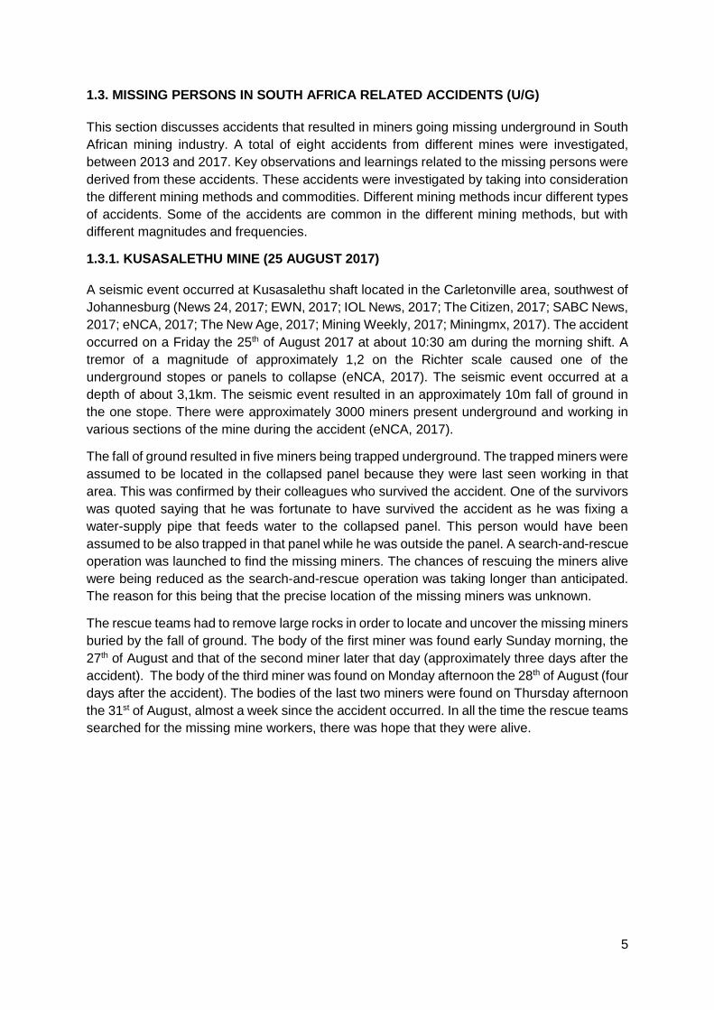
1.3.1. KUSASALETHU MINE (25 AUGUST 2017)
A seismic event occurred at Kusasalethu shaft located in the Carletonville area, southwest of
Johannesburg (News 24, 2017; EWN, 2017; IOL News, 2017; The Citizen, 2017; SABC News,
2017; eNCA, 2017; The New Age, 2017; Mining Weekly, 2017; Miningmx, 2017). The accident
occurred on a Friday the 25th of August 2017 at about 10:30 am during the morning shift. A
tremor of a magnitude of approximately 1,2 on the Richter scale caused one of the
underground stopes or panels to collapse (eNCA, 2017). The seismic event occurred at a
depth of about 3,1km. The seismic event resulted in an approximately 10m fall of ground in
the one stope. There were approximately 3000 miners present underground and working in
various sections of the mine during the accident (eNCA, 2017).
The fall of ground resulted in five miners being trapped underground. The trapped miners were
assumed to be located in the collapsed panel because they were last seen working in that
area. This was confirmed by their colleagues who survived the accident. One of the survivors
was quoted saying that he was fortunate to have survived the accident as he was fixing a
water-supply pipe that feeds water to the collapsed panel. This person would have been
assumed to be also trapped in that panel while he was outside the panel. A search-and-rescue
operation was launched to find the missing miners. The chances of rescuing the miners alive
were being reduced as the search-and-rescue operation was taking longer than anticipated.
The reason for this being that the precise location of the missing miners was unknown.
The rescue teams had to remove large rocks in order to locate and uncover the missing miners
buried by the fall of ground. The body of the first miner was found early Sunday morning, the
27th of August and that of the second miner later that day (approximately three days after the
accident). The body of the third miner was found on Monday afternoon the 28th of August (four
days after the accident). The bodies of the last two miners were found on Thursday afternoon
the 31st of August, almost a week since the accident occurred. In all the time the rescue teams
searched for the missing mine workers, there was hope that they were alive.
6
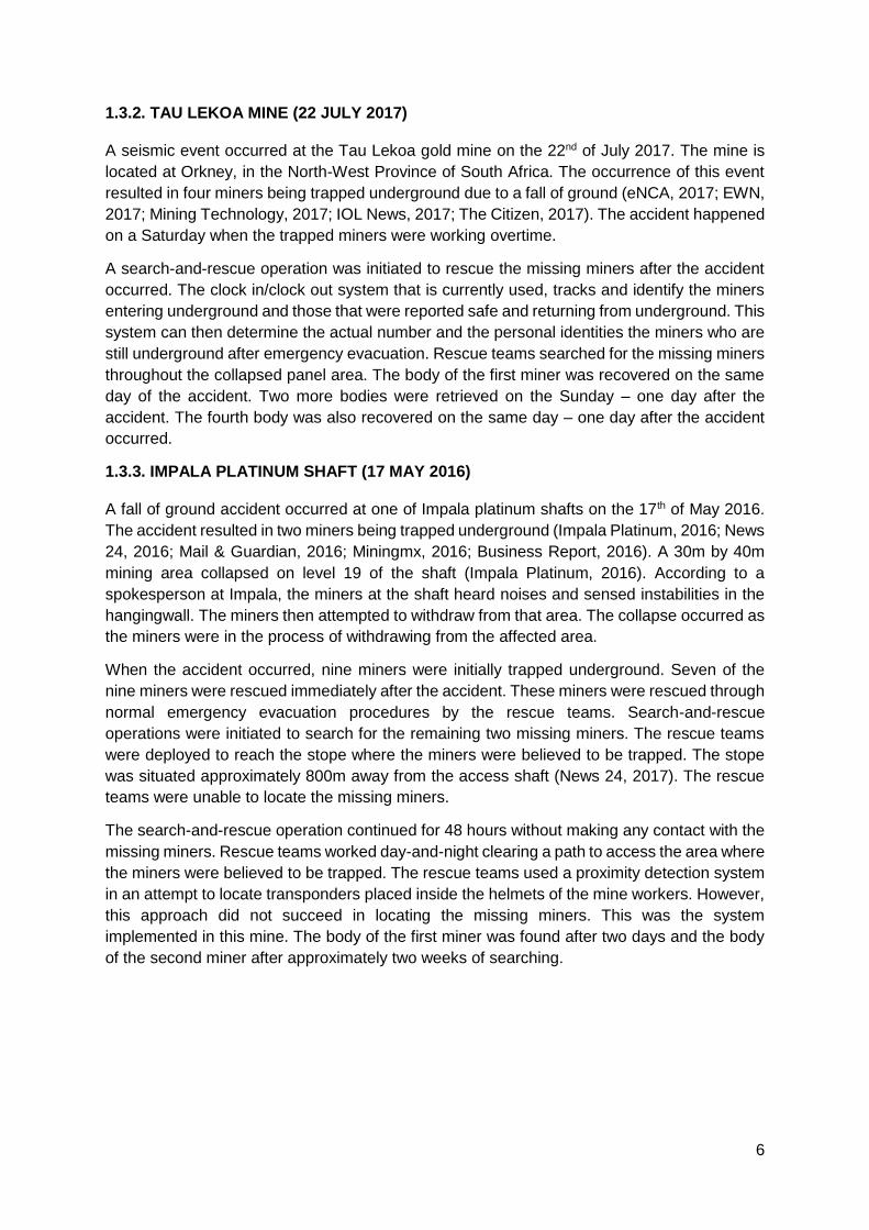
1.3.2. TAU LEKOA MINE (22 JULY 2017)
A seismic event occurred at the Tau Lekoa gold mine on the 22nd of July 2017. The mine is
located at Orkney, in the North-West Province of South Africa. The occurrence of this event
resulted in four miners being trapped underground due to a fall of ground (eNCA, 2017; EWN,
2017; Mining Technology, 2017; IOL News, 2017; The Citizen, 2017). The accident happened
on a Saturday when the trapped miners were working overtime.
A search-and-rescue operation was initiated to rescue the missing miners after the accident
occurred. The clock in/clock out system that is currently used, tracks and identify the miners
entering underground and those that were reported safe and returning from underground. This
system can then determine the actual number and the personal identities the miners who are
still underground after emergency evacuation. Rescue teams searched for the missing miners
throughout the collapsed panel area. The body of the first miner was recovered on the same
day of the accident. Two more bodies were retrieved on the Sunday – one day after the
accident. The fourth body was also recovered on the same day – one day after the accident
occurred.
1.3.3. IMPALA PLATINUM SHAFT (17 MAY 2016)
A fall of ground accident occurred at one of Impala platinum shafts on the 17th of May 2016.
The accident resulted in two miners being trapped underground (Impala Platinum, 2016; News
24, 2016; Mail & Guardian, 2016; Miningmx, 2016; Business Report, 2016). A 30m by 40m
mining area collapsed on level 19 of the shaft (Impala Platinum, 2016). According to a
spokesperson at Impala, the miners at the shaft heard noises and sensed instabilities in the
hangingwall. The miners then attempted to withdraw from that area. The collapse occurred as
the miners were in the process of withdrawing from the affected area.
When the accident occurred, nine miners were initially trapped underground. Seven of the
nine miners were rescued immediately after the accident. These miners were rescued through
normal emergency evacuation procedures by the rescue teams. Search-and-rescue
operations were initiated to search for the remaining two missing miners. The rescue teams
were deployed to reach the stope where the miners were believed to be trapped. The stope
was situated approximately 800m away from the access shaft (News 24, 2017). The rescue
teams were unable to locate the missing miners.
The search-and-rescue operation continued for 48 hours without making any contact with the
missing miners. Rescue teams worked day-and-night clearing a path to access the area where
the miners were believed to be trapped. The rescue teams used a proximity detection system
in an attempt to locate transponders placed inside the helmets of the mine workers. However,
this approach did not succeed in locating the missing miners. This was the system
implemented in this mine. The body of the first miner was found after two days and the body
of the second miner after approximately two weeks of searching.

7
1.3.4. LILY MINE (15 FEBRUARY 2016)
On the 5th of February 2016, at Lily gold mine, near Barberton in the Mpumalanga Province,
a subsidence accident occurred. The collapse occurred near the entrance of the mine after a
crown pillar collapsed (EWN, 2016; Radio 702, 2016; ANN7, 2016; Mining Review Africa,
2016; BBC News, 2016; Sunday Times, 2016; Mail & Guardian, 2016; The Citizen, 2016;
News 24, 2016; The Telegraph, 2016; Mining Weekly, 2016; The New Age, 2016; IOL News,
2016). The collapse caused a cave-in of an 80m depth of rock material that trapped a container
in which three mine workers were working.
A total of 76 underground miners were rescued after the accident and brought to surface
safely. The rescued miners were retrieved through a ventilation shaft of the mine. However,
the three surface workers disappeared into the sinkhole during the collapse with the lamp
room container. Figure 4 shows the aerial view of the collapse, similar to a sinkhole. The
workers were unaccounted for and a search-and-rescue operation was launched.

8
Figure 4: The sinkhole that occurred after the Lily mine disaster where three mine workers are trapped underground (Lowvelder, 2016)

9
1.3.5. KUSASALETHU MINE (22 FEBRUARY 2015)
A fire accident occurred at Kusasalethu shaft on the 22nd of February 2015. There were 486
people present and working underground during the occurrence of the accident. The shaft is
located near the Carletonville area in Johannesburg (News 24, 2015; Harmony Gold, 2015;
BBC News, 2015; Daily Mail, 2015; eNCA, 2015). A fire broke out during maintenance work
on one of the bulk air cooler on level 75 in the mine. At the time of the accident, all mine
employees were notified and advised to follow normal emergency escape procedures and to
withdraw to the nearest refuge bays.
Rescue teams were deployed to contain the fire and rescue the trapped miners. The rescue
teams started reducing ventilation supply to the fire area in order to control and reduce the
burning rate of the fire. The rescue teams then started escorting the miners from the refuge
chambers, level to level, to surface through the shaft. Some of the miners were trapped
approximately 3,5km underground. All employees were safely rescued and brought to surface
without injuries.
1.3.6. DOORNKOP MINE (4 FEBRUARY 2014)
The Doornkop shaft fire accident occurred on the 4th of February 2014. The accident was
caused by a fire break-out that was followed by a fall of ground accident (Reuters, 2014; Mail
& Guardian, 2014; IOL News, 2014; Harmony Gold, 2014; eNCA, 2014). The accident trapped
17 miners at approximately 1,7km below surface. Search-and-rescue operations were initiated
to save the underground missing miners. However, the locations of the trapped miners were
unknown. The mine managed to make contact with eight miners who managed to escape to
the refuge bays. The locations of the remaining nine workers were still unknown.
The fire occurred at a stope (working face) on level 192 that intersected a main intake haulage.
The mine stated that its priority was to simultaneously get the fire under control in order to
reach the eight miners in the refuge bays and locate the other missing miners (Harmony Gold,
2014). The priority was to reach the eight workers in the refuge bays because they were
believed to be still alive. Rescue teams were deployed to search for the missing persons in
various areas underground. The search progress was hampered by smoke and subsequent
rock falls when accessing the affected areas. This was due to the fact that the rescue team
members could not see through these conditions (such as poor visibility due to smoke).
On the 6th of February 2014, rescue teams were still searching for the missing miners. Eight
of the nine missing miners were found dead. Rescue operations continued to search and
locate the one missing miner. The bodies of the eight trapped miners were discovered two
days after the accident. The body of the last missing miner was discovered three days later.
The bodies of the miners were underground for at least 48 hours before being found due to
their locations being unknown.

10
1.3.7. WEST RAND MINE (25 NOVEMBER 2013)
Four persons were trapped at the abandoned West Rand mine near Robertsville in
Johannesburg (eNCA, 2013; IOL News, 2013; Mining Review Africa, 2013). The accident
occurred at an old, unused shaft. The trapped persons had entered the mine illegally. The
illegal miners were trapped underground for at least three days, from the 25th of November
2013. Rescue teams were deployed to search and rescue the trapped illegal miners. The
rescue teams searched in various areas. The rescue teams managed to reach the locations
of the trapped persons after searching in random areas.
Locating the trapped miners took time due to not knowing the exact locations of the trapped
miners. Rescue teams managed to reach the trapped people safely. The people were then
removed from the mine with no major injuries sustained although they were trapped for three
days. Even though these people were mining illegally, there was still a need to rescue them
from underground. These people would not have been accounted for by the mine.
1.3.8. BATHOPELE SHAFT (20 JULY 2013)
Two miners were found dead at Bathopele shaft in Rustenburg after being trapped
underground (News 24, 2013). The accident occurred on the 20th of July 2013 due to a sudden
fall of ground inside the mine (News 24, 2013). The fall of ground accident resulted in two
miners being trapped underground. The bodies of the two miners were found after a long
search-and-rescue operation. The search process was prolonged due to not knowing the
locations of the trapped miners. The duration of the search-and-rescue operation lasted for
almost five days. It is unknown whether the two miners died from being trapped underground
for a long time or they died instantly during the fall of ground.

11
1.3.9. SIGNIFICANCE OF AVAILABLE INFORMATION (1.3.1 – 1.3.8)
Section 1.3.1 to 1.3.8 shows that there is significant number of miners who are fatally injured
after having been trapped or lost underground. The miners become trapped or lost in unknown
locations after the occurrence of accidents. Falls of ground, gas explosions and underground
fires are amongst the most common accidents that trap miners in the South African mining
industry. These accidents occurred in the different mining methods. The missing miners may
die instantly from these accidents, but also from being trapped underground for a longer period
without emergency assistance. The longest search-and-rescue operation lasted for 14 days
while the Lily mine workers are yet to be found. The minimum search-and-rescue operation
took at least 2 days. The effectiveness of search-and-rescue operations is determined by the
minimum time taken to locate and rescue the missing persons.
The lack of essential positioning information such as the exact locations and number of the
missing persons often result in failed and/or prolonged search-and-rescue operations. This
does not only result in long lasting search-and-rescue operations, but subsequent fatalities. In
some cases, it cannot be proved whether the miners died instantly during the accident or as
a result of being trapped underground. Search-and-rescue operations last longer than
expected due to the locations of the missing persons being unknown. As a result, the rescue
teams were deployed to search for the missing persons in random and presumed areas.
The presumed locations can be classified as the areas in which the missing miners were last
seen and the areas where they were expected to be working before the accident occurred.
However, this information is often insufficient and inaccurate in locating the missing persons.
Even at the presumed locations it can be challenging to locate the missing miners. Key
observations were made to understand how and why miners go missing for longer
underground. The key learnings will be used in in the results section in Chapter 4 to derive
going missing scenarios – scenarios in which miners can go missing.

12
Table 1: Summary of South African accidents that led to mine personnel missing underground
Mine Year of
accident
Cause of
accident
Number
of
trapped
or
missing
persons
Number
of
rescued
persons
Number
of
fatalities
Duration
of search-
and-
rescue
(days)
Rescue attempt Key observations
Kusasalethu 2017 Fall of
ground
5 0 5 6 A search-and-rescue operation was
conducted at presumed locations. The
operation could have been quicker if a
missing person locator system was
implemented beforehand. The only
available information was the number of
missing persons.
The mine was fortunate that the missing
persons were actually trapped at their
presumed locations. If multiple panels
were affected, during shift change, it
would have been difficult to presume the
locations of missing persons without a fit
for purpose system.
Tau Lekoa 2017 Fall of
ground
4 0 4 ~5 A search-and-rescue operation was
conducted at the proximity of the
collapsed panel. The rescue teams
searched for the missing persons in the
areas where the trapped persons were
last seen working.
The missing persons succumbed to their
injuries due to the search-and-rescue
operation lasting longer. The rescue
teams did not have accurate locations of
the missing persons for quicker rescue
operation.
Impala 2016 Fall of
ground
9 7 2 >14 A search-and-rescue operation was
conducted at the area that had collapsed.
The rescue teams had to remove large
amounts of broken rock to locate the
trapped workers at presumed locations.
The exact area in which the persons were
trapped was known, but the exact
locations of the trapped persons were
unknown. The rescue teams searched in
random areas within the collapsed area.
Lily mine 2016 Ground
collapse
and
sinkhole
3 0 3 Pending Various rescue attempts were initiated.
None of these attempts were successful,
even though the locations of the trapped
miners were reasonably known from
surface.
Unstable ground conditions caused
delays during the search-and-rescue
operation. The workers were trapped by
the ground collapse and the exact
location of the container was presumed.

13
Mine Year of
accident
Cause of
accident
Number
of
trapped
or
missing
persons
Number
of
rescued
persons
Number
of
fatalities
Duration
of search-
and-
rescue
(days)
Rescue attempt Key observations
Kusasalethu 2015 Fire 486 486 0 - The rescue teams were required to firstly
contain the fire, before even starting with
the search-and-rescue operation. This
affected the chances of rescue teams
saving potential survivors.
The missing persons could not be
detected easily due to smoke from the
fire. The workers were trapped by fire and
this required adequate sizing of rescue
efforts.
Doornkop 2014 Fire 17 9 8 >2 A search-and-rescue operation was
initiated. The rescue teams searched for
the missing workers in various
workplaces due to not knowing the exact
locations of the missing miners.
Search progress was hampered by
smoke and subsequent rock falls, and
this made it difficult to locate the missing
persons. The rescue teams struggled to
see through the smoky areas.
West Rand 2013 Shaft
collapse
4 4 0 >3 Rescue teams were deployed to search
and rescue the illegal miners
underground. The rescue teams search
for an unknown number of trapped
persons in random areas.
The trapped persons were illegal miners
who entered an old shaft illegally. The
number of trapped persons could not be
determined and even an available
system could not have helped.
Bathopele 2013 Fall of
ground
2 0 2 5 Rescue teams were deployed for the
search-and-rescue operation. The rescue
teams searched at the proximity of the fall
of ground as a starting point to locate the
missing workers.
The information used to locate the
missing workers was presumed and not
guaranteeing success in locating and
rescuing the missing persons in time to
save lives.

14
1.4. INTERNATIONAL MISSING PERSONNEL ACCIDENTS (U/G)
This section discusses accidents that resulted in miners going missing underground in various
countries around the worldwide. These accidents were investigated from various mining
operations that employ different mining methods. The common and major causes of the
accidents are investigated to derive useful learnings related to missing persons. These
accidents where investigated between 2006 and 2016. These accidents cover a wide range
of commodities in which the mining methods and working conditions are different from one
mine another (e.g. number of miners and depth of operation).
1.4.1. SAN JOSE MINE (5 AUGUST 2010)
An underground cave-in or ground collapse occurred at San Jose copper-gold mine on the 5th
of August 2010 in Chile (Varas, 2015; CNN, 2010; BBC News, 2010; Reuters, 2010; The
Guardian, 2010; The Star, 2010; The Guardian, 2010; The Telegraph, 2010). The 121-year-
old mine is located approximately 45km north of the Copiapo city in Chile. As a result of the
cave-in, 33 miners (now known as “The 33”) became trapped underground. The workers were
trapped at a depth of approximately 700m underground and approximately 5km away from
the mine entry point. The trapped workers attempted to escape through a ventilation shaft
system but failed to do so because the shaft was still experiencing ground movements.
Search-and-rescue operations were initiated to save the missing miners who were believed to
be still alive. The 33 miners managed to escape the accident and moved into a refuge
chamber. The refuge bay was resourced with survival items such as canned foods and water.
Multiple rescue attempts were launched to rescue the 33 missing miners. The first attempt
was to enter the mine through an alternative passage. However, the passage was found to be
blocked by fallen rock and threats from ground movement as a result of the collapse.
A second attempt, after another collapse occurred on 7 August 2010 and forced the rescue
team to try an access the mine via a ventilation shaft. This rescue approach was halted as it
could cause further rock strata movements. Thirdly, drill rigs were taken to drill boreholes of
16cm in diameter in order to locate and rescue the missing miners. Figure 5 shows the
boreholes that were drilled during the rescue attempts. The hardness of the rock and depth
caused the boreholes to diverge from targeted areas. The boreholes were drilled to the areas
in which the miners were believed to be trapped. Seven boreholes in total were drilled in
search of the location of the trapped mine workers.

15
Figure 5: Boreholes drilled from surface in search of the trapped 33 workers in the Chilean disaster (RTE News, 2010)
On the 22nd of August 2010, after 17 days of searching, an eighth borehole was drilled to a
depth of 688m, about 20m from the refuge chamber where the miners had escape to. This
borehole located the trapped workers and rescue plans were prepared. Even though the
drilling method worked, it was time consuming and could have led to the missing miners dying
if the refuge bay was not well stocked with the survival items. It took a multinational effort that
costed up to R280 million to safely rescue the 33 workers that were trapped underground for
69 days before being rescued.
1.4.2. CRANDALL CANYON MINE (6 AUGUST 2007)
On the 6th of August in 2007, Crandall Canyon mine experienced strata collapse, and six
miners became trapped underground in the USA (The Salt Lake Tribune, 2007; KSL News,
2007; CNN, 2007; BBC News, 2007; The New York Times, 2007; Physics.org, 2013). The
miners were trapped at a depth of 457m and at approximately 5,5km from the entrance of the
mine. Rescue teams were dispatched throughout the mine to search for the trapped workers.
However, search-and-rescue operations were hindered by additional seismic activities
causing further delays in the process of locating the trapped miners. The search-and-rescue
process was estimated to last up to six weeks due to the required clearing of rubble material
and installing supports on the passage ways.

16
Figure 6: Plan view of the underground sections with presumed locations of trapped workers and positions of boreholes (University of Utah, 2007)

17
On the 9th of August 2007 (3 days later) after the initial search-and-rescue attempt failed,
drilling was used to attempt to locate the trapped miners. Figure 6 shows the areas that
collapsed and the positions of the boreholes. Firstly, a 6,3cm diameter boring machine was
brought to drill up to a depth of 549m into the presumed location of the trapped miners. After
the first drill, there were no signs of human activities. Drilling accuracy was a problem and the
drill missed the targeted areas in which the trapped workers were presumed to be located. A
total number of seven boreholes were drilled to try and locate the missing miners (Figure 7).
However, the drilling method was unsuccessful in locating the missing miners.
Figure 7: The seven boreholes drilled in search of the trapped mine workers at the Crandall Canyon mine (KSL.com News, 2007)
The first two boreholes were targeted to the locations where the miners were believed to be
located during the collapse. This is the same area in which they were last seen working.
Robotic cameras were other attempts tried to locate the missing miners. These robots were
lowered through the second borehole but could not locate any of the trapped miners. The
cameras were affected by poor lighting at the bottom of the borehole.
A second collapse in the mine occurred on the 16th of August 2007 and this delayed the
search-and-rescue operation further. The collapse resulted in three fatalities and six injuries
of the rescue teams. The rescue operation was then suspended, and the rescue teams were
withdrawn from the tunnels. The sixth borehole was drilled to the location where the trapped
workers were last known to be working (see Figure 7). The sixth borehole was said to be the
last attempt after no signs of life were detected. Search efforts were officially called off on the
1st of September 2007 after the seventh hole was unsuccessful and this was after four weeks
of searching. The trapped miners were never found and later declared dead as the bodies
were never recovered.

18
1.4.3. PIKE RIVER MINE (19 NOVEMBER 2010)
The Pike River mine accident happened on the 19th of November 2010 as a result of a
methane explosion in New Zealand (Reuters, 2010; The Courier Mail, 2010; The New Zealand
Herald, 2010; The Australian, 2010). A series of other explosions occurred after the initial
event. During the series of these explosions, the exact number of people remaining
underground was unknown. Different sources reported various figures which were incorrect
ranging between 25 and 33. It was eventually confirmed that there were 31 miners and
contractors present inside the mine during the explosion. Two of the 31 people managed to
escape the accident and with the other 29 miners remaining trapped underground. A second
explosion occurred on the 24th of November 2010 and after this explosion the remaining 29
trapped miners were presumed dead.
Figure 8: Fire flames coming out the ventilation shaft after the Pike River disaster (The National Business Review, 2013)
A borehole was drilled to an area in which the miners were believed to be located. Figure 8
shows the damage that was caused by the first explosion on the ventilation shaft. A search-
and-rescue operation was initiated, but it was delayed as rescue teams were attempting to
enter the mine. The rescue operation was stopped as it was declared impractical and very
unsafe for the rescue teams. The rescue teams tried to search for miners tapping on pipe
columns or voices shouting for help coming from survivors, but unfortunately nobody was
found. Several robotic vehicles were dispatched underground during the search, rescue, and
recovery operation. Four robotic vehicles were hindered by water accumulations and cave-
ins.
1.4.4. SAGO MINE (2 JANUARY 2006)
The Sago mine accident in the USA was caused by an underground explosion that occurred
on the 2nd of January 2006 at around 06H30 during the morning shift (The New York Times,
2006; BBC News, 2006; ABC News, 2006). A blast caused a ground collapse in the mine and
13 miners became trapped for almost two days. The explosion occurred during the first
working shift. This was after the mine had re-opened from the New Year’s holidays. Two utility
vehicles were transporting miners to the working areas. The vehicle at the back managed to
escape the explosion while the other vehicle had passed the point of the explosion. After the
explosion, 13 miners were trapped and only one person survived.

19
Boreholes were drilled to the last known position of the trapped workers. However, the rescue
operation was delayed due to high levels of methane and carbon dioxide. Water seepages,
explosive gas concentrations and unsafe roof conditions were some of the other hazards that
were delaying the progress of the search-and-rescue teams. The rescue teams used
telephones to communicate with one another during the search-and-rescue operation. The
telephones were disconnected in every checkpoint in order to avoid methane explosions. A
robotic scouting vehicle was deployed underground during the search-and-rescue operation.
However, the robotic vehicle was withdrawn from underground after it became stuck in mud
at about 790m from the mine entrance. The rescue teams were also withdrawn from the
search after nine hours due to a risk of further explosions.
Microphones and video cameras were lowered through the boreholes to search for signs of
life. As a third borehole was being drilled, it encountered groundwater and it could not be
completed. A third borehole (the fourth when including the abandoned borehole) was drilled
in the area where the miners were trained to escape to and barricade themselves in the case
of an explosion. The miners carry Self-Contained Self-Rescuer (SCSR) devices supplying
them with breathing oxygen-air lasting for an hour. This gives the rescue teams about an hour
to locate the missing miners in order to save lives.
The first body was found on the 3rd of January 2006 and there was a rumour that the other
bodies were also found which was not true as confirmed by the rescue teams. On the 4th of
January 2006 (which was 41 hours since the first explosion occurred), 12 of the trapped
workers were found dead. One person was found alive, but the person was in a critical
condition. The remaining bodies were located at the face, which was approximately 4km from
the mine entrance.
The only survivor of the accident, Mr Randal L. McCloy Jr, wrote a letter, three weeks after
the disaster. Some extracts from the letter stated “the mine filled quickly with fumes and thick
smoke and that breathing conditions were nearly unbearable…at least four of the rescuer’s
emergency oxygen packs were not functioning…they attempted to signal our location to the
surface by beating on the mine bolts and plates. We found a sledgehammer, and for a long
time we took turns pounding away. We had to take off the rescuers in order to hammer as
hard as we could. This effort caused us to breathe much harder. We never heard a responsive
blast or shot from the surface. After becoming exhausted, they stopped trying to signal”.
1.4.5. UPPER BIG BRANCH MINE (5 APRIL 2010)
The Upper Big Branch mine accident occurred on 5th of April 2010 at the coal mine located in
West Virginia, USA (West Virginia Office of Miner’s Health, Safety and Training, no date;
McAteer et al., 2011; Mine Safety and Health Administration, 2014; West Virginia Public
Broadcasting, 2017). A coal dust explosion occurred at approximately 300m below surface.
The accident resulted in 29 out of 31 miners being killed. The accident was reported to have
been caused by flagrant safety violations. The main cause of the explosion could not be
confirmed. Initial reports stated that 25 miners died after the explosion and four others went
missing underground. The remaining four missing workers were found after four days.
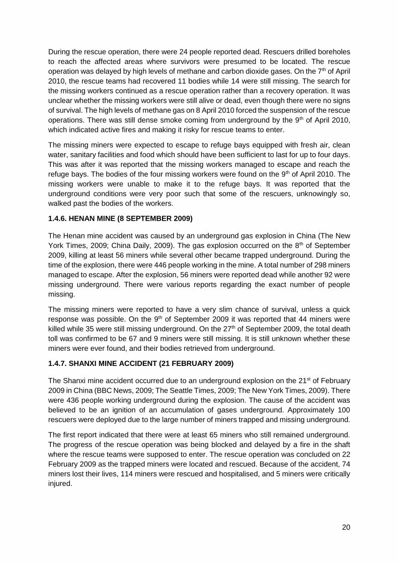
20
During the rescue operation, there were 24 people reported dead. Rescuers drilled boreholes
to reach the affected areas where survivors were presumed to be located. The rescue
operation was delayed by high levels of methane and carbon dioxide gases. On the 7th of April
2010, the rescue teams had recovered 11 bodies while 14 were still missing. The search for
the missing workers continued as a rescue operation rather than a recovery operation. It was
unclear whether the missing workers were still alive or dead, even though there were no signs
of survival. The high levels of methane gas on 8 April 2010 forced the suspension of the rescue
operations. There was still dense smoke coming from underground by the 9th of April 2010,
which indicated active fires and making it risky for rescue teams to enter.
The missing miners were expected to escape to refuge bays equipped with fresh air, clean
water, sanitary facilities and food which should have been sufficient to last for up to four days.
This was after it was reported that the missing workers managed to escape and reach the
refuge bays. The bodies of the four missing workers were found on the 9th of April 2010. The
missing workers were unable to make it to the refuge bays. It was reported that the
underground conditions were very poor such that some of the rescuers, unknowingly so,
walked past the bodies of the workers.
1.4.6. HENAN MINE (8 SEPTEMBER 2009)
The Henan mine accident was caused by an underground gas explosion in China (The New
York Times, 2009; China Daily, 2009). The gas explosion occurred on the 8th of September
2009, killing at least 56 miners while several other became trapped underground. During the
time of the explosion, there were 446 people working in the mine. A total number of 298 miners
managed to escape. After the explosion, 56 miners were reported dead while another 92 were
missing underground. There were various reports regarding the exact number of people
missing.
The missing miners were reported to have a very slim chance of survival, unless a quick
response was possible. On the 9th of September 2009 it was reported that 44 miners were
killed while 35 were still missing underground. On the 27th of September 2009, the total death
toll was confirmed to be 67 and 9 miners were still missing. It is still unknown whether these
miners were ever found, and their bodies retrieved from underground.
1.4.7. SHANXI MINE ACCIDENT (21 FEBRUARY 2009)
The Shanxi mine accident occurred due to an underground explosion on the 21st of February
2009 in China (BBC News, 2009; The Seattle Times, 2009; The New York Times, 2009). There
were 436 people working underground during the explosion. The cause of the accident was
believed to be an ignition of an accumulation of gases underground. Approximately 100
rescuers were deployed due to the large number of miners trapped and missing underground.
The first report indicated that there were at least 65 miners who still remained underground.
The progress of the rescue operation was being blocked and delayed by a fire in the shaft
where the rescue teams were supposed to enter. The rescue operation was concluded on 22
February 2009 as the trapped miners were located and rescued. Because of the accident, 74
miners lost their lives, 114 miners were rescued and hospitalised, and 5 miners were critically
injured.

21
1.4.8. LUOTUOSHAN COAL MINE (1 MARCH 2010)
The Luotuoshan mine accident occurred on the 1st of March 2010 in China after a large amount
of water accumulated and flooded the coal mine (BBC News, 2010; SINA, 2010; People’s
Daily, 2010). There was a total of 77 miners working underground during the accident. A
mining crew broke into a large pool of limestone water during the morning shift. The accident
required the largest rescue mobilization as 20 384 people in 40 rescue teams were called to
the mine (SINA News, 2010). During the evening of the accident, 45 miners were rescued,
and one person was confirmed dead. After 14 days of search, there were still 31 miners
trapped and missing underground.
The probability of survival of the trapped workers decreased with time while water continued
to flood the mine. The rescue operation continued for an additional 14 days. Infrared
surveillance cameras and echo megaphones were deployed to the mine, but there were no
signs of life detected. There were still no signs of life after the two-week long rescue operation.
The rescue operation was declared a failure on the 14th of March 2010. The missing miners
could not be located.
1.4.9. WANGJIALING COAL MINE (28 MARCH 2010)
The Wangjialing coal mine flooding accident occurred on the 28th of March 2010 in China (BBC
News, 2010; CBS News, 2010; Reuters, 2010). Some parts of the underground workings
became flooded when miners broke through to an abandoned mine. The abandoned mine
consisted of old shafts filled with water. Rescue teams were called to the mine and began
pumping out water before searching for the missing miners. A total of 261 people were working
underground when the flooding incident occurred. Over 100 miners were reported to have
escaped the accident but 153 were trapped and missing underground. The missing miners
were trapped underground in various working areas. By the 5th of April 2010 (three days after
the accident occurred), a number of miners were still missing underground.
The rescue efforts consisted of over 3 000 rescuers who were pumping out water from the
mine. Only nine of the trapped miners were rescued after a week. An additional 115 of the
missing miners were rescued on the same day, while there were still 15 trapped miners
underground. On the 9th of April 2010, 23 miners were confirmed to have died. There were
difficulties in reaching the trapped miners. On the 8th of April 2010 (12 days after the accident
occurred), officials from the rescue teams stated that the chances of survival of the 14 trapped
workers amongst the 15 were almost zero. During the search-and-rescue operation, the
rescue teams were delayed by poor visibility, mud, high water flow rates and low oxygen
levels.
1.4.10. YUANYANG MINE (13 MAY 2010)
The Yuanyang Colliery outburst occurred on the 13th of May 2010 in Guizhou, China. An
underground outburst occurred while there were 31 people working underground at the time.
At least 21 people were reportedly killed instantly as a result of the accident (BBC News, 2010;
China Daily, 2010; Euro News, 2010). Seven mine workers escaped the outburst while 24
miners became trapped underground. Rescue teams were called to the mine to conduct
search-and-rescue operations to save the missing miners.

22
It was difficult to determine the exact number of missing miners. The identities of the missing
miners were also not available at the time of the accident. The rescue teams started searching
for the trapped miners in random areas throughout the mine. An unknown number of illegal
miners was also underground at the time of the accident. It was later realised that the accident
was caused by a toxic gas outburst during an illegal mining operation that was happening in
the mine.
1.4.11. XIAOJAWAN COAL MINE (29 AUGUST 2012)
The Xiaojawan coal mine accident occurred on the 29th of August 2012 due to a gas explosion
in China. The accident killed at least 45 miners, while others were trapped underground
(Reuters, 2012; CRIEnglish, 2012). The explosion occurred when there was a total of 154
miners working underground. Out of the 154 miners trapped underground, 107 managed to
escape without the help of rescue teams. Search-and-rescue operations began with more than
300 rescuers were called to the mine to rescue the trapped miners.
1.4.12. ERMENEK MINE (28 OCTOBER 2014)
The Ermenek mine accident occurred on the 28th of October 2014 at a coal mine in Ermenek
town, Turkey (Reuters, 2014; BBC News, 2014; MINING.com, 2014; Middle East Eye, 2014;
Candemir, 2014). The accident was caused by a broken water pipe that flooded the mine. The
mine operations were between 300 - 350m deep underground. As a result of the flooding, 18
miners became trapped and were reported missing underground, while another 20 miners
escaped from the accident. Rescue teams were called to rescue the trapped miners.
The rescue teams included a team of divers that continued the search for the missing miners.
The chances of survival of the trapped miners were slim, unless the trapped miners managed
to reach the refuge bays. The Ermenek mine accident resulted in eight officials of the mine
arrested as only two bodies out of the 18 trapped miners were located and retrieved from
underground.
1.4.13. SOMA MINE (13 MAY 2014)
The Soma mine accident occurred on the 13th of May 2014 after an explosion occurred at the
mine in Turkey (The Guardian, 2014; Aksogan et al., 2014; The Telegraph, 2014; BBC News,
2014). The explosion caused underground fires that lasted for almost 3 days. This accident
was categorised as one of the worst mining disasters in Turkey, with 301 fatalities. The
explosion occurred during shift change while there were 787 people present underground at
the time. The bodies of the miners were retrieved on the 17th of May 2014, which was four
days after the accident.
Most of the miners were killed from carbon monoxide poisoning and nearly 600 were trapped
underground during the accident. The number of people underground at the time of the
explosion was uncertain. This is due to the large number of people present underground
during shift change, some having exited while others still entering the shaft. Following the
accident, rescue teams were deployed to the mine. The miners were believed to be trapped
approximately 4km from the mine entrance. The fires made it difficult for the rescue teams to
locate the missing miners.

23
1.4.14. GLEISION MINE (15 SEPTEMBER 2011)
The Gleision mine accident happened on the 15th of September 2011 in Swansea Valley,
Wales (Health and Safety Executive, 2011). A blast released a large volume of water from old
workings, which rushed into the active mining areas. This occurred when six out of eight
miners went underground to detonate the first round of explosives on the face. The volume
and speed of the water inrush trapped four of the six miners while the other two managed to
escape to surface.
The Mine Rescue Services of Wales was called to the mine after the four miners were reported
missing underground. The mine did not have all the necessary resources to conduct the
search-and-rescue operation. Neighbouring mines and mining equipment suppliers were
required to provide assistance. The mine plans appeared to be inaccurate when it was used
to search of the missing mine workers. The miner who escaped travelled a long distance to
reach the surface.
Figure 9: Point A to B shows the route that the mine workers who escaped used to exit the mine (The Health and Safety Executive, 2015)
The rescue teams were deployed underground to explore the route that the miners who
escaped used. In Figure 9, route A to B is the route that the other miners used to travel to
surface. Divers searched all the accessible roadways, but could not find any signs of life. The
rescue teams were assisted by Urban Search and Rescue teams to search in any open
spaces. The area in which the inrush occurred was unsafe to enter while the missing miners
were believed to be in that area. The rescue teams had to tunnel through a stone pack in order
to gain access to the breach from the opposite side of the inrush stall. All four missing miners
were located around the inrush source area, some partly submerged in silt. The search-and-
rescue lasted for about 32 hours involving hundreds of rescuers.

24
1.4.15. ZONGULDAK MINE (17 MAY 2010)
The Karadon mine accident occurred on the 17th of May 2010. A methane explosion occurred
at coal mine in Zonguldak Province, Turkey (CNN News, 2010; MINING.COM, 2013). The
explosion resulted in a total number of 30 miners being fatally injured underground. Rescue
teams were deployed to locate the missing 30 miners who were working underground at the
time of the accident. The rescue teams managed to retrieve 28 bodies on the 20th of May 2010
(four days after the explosion). The remaining two bodies were only recovered after eight
months of searching all over the mine. Even though the miners were killed instantly by the
explosion, there was still a need to retrieve their bodies.
1.4.16. VORKUTA MINE (25 FEBRUARY 2016)
The Vorkuta mine accident occurred on the 25th of February 2016 at the Severnaya coal mine
located in Vorkuta, Russia (Los Angeles Times, 2016; TASS Russian News Agency, 2016;
BBC News, 2016; CNN News, 2016). The accident was a result of an underground methane
explosion. There were 111 people working underground when the accident occurred in the
mine. A series of further explosions occurred, killing 36 people including 31 miners and 5
rescue personnel who were searching for the trapped miners.
The explosion occurred at approximately 780m below surface and some distance from the
mine entrance. The mine also experienced a partial collapse due to a fall of ground in which
four miners were killed immediately and trapping 26 miners underground. During the
explosion, 81 miners were safely evacuated from the mine with minor injuries sustained. At
least 500 people were called to the mine to assist with the rescue operation.
The rescue operation was suspended after it was declared that all the missing miners were
deceased. Special robotic equipment, equipped with several video cameras, gas sensors and
infrared sensing devices were deployed underground to survey the mine for damages and
determine if it was safe for rescue teams to re-enter. The robots were designed to work in
complete darkness conditions, excessive smoke and heavy dust. At this time, it was believed
that the trapped miners would not survive the explosions.
1.4.17. BEACONSFIELD MINE (25 APRIL 2006)
The Beaconsfield mine accident occurred on the 25th of April 2006 at the gold mine in Australia
(News.com.au, 2006; The Sydney Morning Herald, 2006; CNN News, 2006; ABC News, 2006;
The Sydney Morning Herald, 2007; ABC News, 2006). A seismic event triggered a fall of
ground inside the mine when 17 miners were present and working underground. The accident
trapped three miners underground, while the other 14 managed to escape to a safe area.
Regarding the three missing miners, one was killed after the rock fall accident and the other
two were still alive and trapped underground.
The two missing miners managed to survive from groundwater seeping from and through
collapsed rock. The trapped miners stayed underground without eating for a few days, and
only shared a muesli bar. Experts believed that there was no way out for the trapped miners
based on the magnitude of the collapse. The two missing miners were trapped 925m
underground for a total 321 hours (about 14 days).

25
Search and rescue efforts started on the 26th of April 2006 by clearing the collapsed rock. The
rescue operation made use of a remote-controlled earth-mover to clear rock at the collapsed
area. The body of the killed miner was found and retrieved on the 27th of April 2006 within the
vicinity of the shaft. On the 29th of April 2006, the rescue teams started blasting a new tunnel
using explosives to access blocked areas of the mine. Two rescuers (the underground
manager and a supervisor at the mine) breached safety protocols to enter into a level (level
925) where the rock fall occurred. The two rescuers shouted out and the trapped mine workers
responded. The trapped miners were only located on the 30th of April 2006 using thermal
imaging cameras and microphones picking up voices.
1.4.18. RASPADSKAYA MINE (8 MAY 2010)
The Raspadskaya mine accident occurred due to an underground methane explosion gas on
the 8th of May 2010 in Russia (CNN News, 2010; The Independent, 2010; BBC News, 2010).
Four hours later, a second explosion occurred and caused a collapse in the ventilation shaft.
A search-and-rescue operation was launched to rescue the 24 trapped miners. It was reported
that 66 miners were fatally injured, at least 99 miners were injured and 24 were still trapped in
unknown locations.
Search-and-rescue operations continued for 10 days without locating the missing miners. The
government wanted search-and-rescue operations to continue until it was clear that all
possible efforts have been taken to locate and save the lives of the miners trapped
underground. It was only after the 18th of May 2010 that the underground locations and
conditions of the miners could be confirmed.
1.4.19. ZASYADKO COAL MINE (4 MARCH 2015)
The Zasyadko coal mine accident occurred on the 4th of March 2015 in Ukraine (BBC News,
2015; KyivPost, 2015; CNN News, 2015; IndustriALL, 2015; World Social Web Site, 2015; The
Independent, 2015). The accident was caused by a gas explosion when 230 people were
working underground. There were conflicting reports over the actual number of miners fatally
injured and those missing. The first report indicated that 23 people died instantly while other
sources reported that about 50 miners were still trapped underground. Officials from the
Ukraine government suspected that as many as 33 people might have died. Search-and-
rescue operations recovered over 200 bodies. It was believed that there were still 32 miners
missing underground.

26
1.4.20. SIGNIFICANCE OF AVAILABLE INFORMATION (1.4.1 – 1.4.19)
The exact number of people missing underground was unknown in some of the accidents (e.g.
Zasyadko, Shanxi, Yuangang and Luotuoshang mine accidents). The underground missing
persons may include unregistered people such as illegal miners (e.g. Yuanyang mine
accident) present underground at the time of the accident. The number of persons or
employees present underground is expected to be the highest during change of shift. The
largest number of people who were fatally injured by a single accident was during a shift
change (Soma coal mine). The time of the accident is critical regarding the total number of
persons that can be potentially trapped underground. The larger the number of people
missing, the more complicated and complex the search-and-rescue operation will be.
The commonly used method for finding missing persons in the past accidents was to drill into
presumed locations (e.g. San Jose, Crandall Canyon and Sago mine accidents). However,
this method was ineffective in locating missing miners. This method was also found to be
costly and time consuming as several boreholes needed to be drilled in search of the missing
persons. It can take several days to drill a single borehole, depending on the depth of the mine
and the presumed locations of the missing persons. The boreholes are drilled without any
guarantee that the missing persons are located in those areas.
Some search-and-rescue operations were successfully planned and executed, some were
only successful by luck, and some failed completely, leaving workers trapped underground.
The past mining accidents have shown that mine rescue teams usually do not have sufficient
information regarding the locations and total number of the missing persons. This information
is necessary for the planning of search-and-rescue operations.
The accidents also shown that missing persons do their utmost best to stay alive and hope
that help is underway (e.g. Beaconsfield and San Jose mine accidents). In some accidents,
the missing miners were declared dead without evidence or retrieving their bodies from
underground (e.g. Pike River and Henan mine accidents). Table 2 summarises the past
accidents from various international countries that resulted in people going missing
underground. Table 2 illustrates the number of people who were trapped, number of people
who were rescued, number of fatalities as well as the duration of the search-and-rescue
operation. Furthermore, key learnings were drawn from each accident-scenario.

27
Table 2: Summary of international accidents that led to persons trapped underground
Mine Year of
accident
Cause of
accident
Number
of trapped
or missing
persons
Number
of
rescued
persons
Number
of
fatalities
Duration
of search-
and-
rescue
(days)
Rescue attempt Key observations
San Jose
copper-gold
mine (Chile)
2010 Cave-in due to
ground
collapse
33 33 0 69 Various rescue attempts were
launched to rescue the trapped
workers. The rescue attempts
included entering the mine and
drilling boreholes.
The rescue operation was conducted
by drilling boreholes to presumed
locations and this process was time
consuming and risky to the trapped
persons.
Crandall
Canyon coal
mine (USA)
2007 Strata collapse 6 0 Unclear 28 Several boreholes were drilled at
presumed areas to intersect the
locations of the trapped miners.
The drilling technique to locate the
trapped miners was long-lasting,
ineffective, costly and time consuming.
Pike River coal
mine (New
Zealand)
2010 Methane
explosion
31 2 29 Unclear Rescue attempts launched
included drilling into presumed
locations, robotic scouting and
search-and-rescue operations.
There was a series of explosions and
this prevented rescue teams to enter
underground to search for the trapped
persons.
Sago coal
mine (USA)
2006 Underground
gas explosion
13 1 12 2 Robotic vehicles were used to
locate the trapped miners due to
the risk of further explosions
underground.
The trapped miners tried to stay alive
and made use of a system that was in
place to signal their location and the
current system failed.
Upper Big
Branch coal
mine (USA)
2010 Coal dust
explosion
31 2 29 4 A search-and-rescue operation
was launched to locate and rescue
the trapped miners.
The rescue operation was hampered
by high levels of methane gas which
posed a threat to the rescuers.
Henan coal
mine (China)
2009 Underground
gas explosion
446 298 Unclear Unclear A search-and-rescue operation
was launched to locate an
unknown number of workers.
There were inconsistencies regarding
the number of missing persons and
those who had died after the explosion.
Shanxi coal
mine (China)
2009 Ignition of
accumulated
gases
436 362 74 2 The total number of missing
persons during the rescue
operation was not clear.
The unknown number of missing
persons could have affected the sizing
of the required rescue efforts.

28
Mine Year of
accident
Cause of
accident
Number
of trapped
or missing
persons
Number
of
rescued
persons
Number
of
fatalities
Duration
of search-
and-
rescue
(days)
Rescue attempt Key observations
Luotuoshan
coal mine
(China)
2010 Water
inundation
77 56 31 14 and
pending
The launched search-and-rescue
operation lasted for two weeks
without locating the missing
persons.
The continued inflow of water affected
the rescue operation and the rescue
operation was eventually declared a
failure
Wangjialing
coal mine
(China)
2010 Mine was
flooded by
water
153 Unclear 23 Unclear The search-and-rescue operation
consisted of over 3000 rescuers,
but the missing persons were only
located after about a week.
Rescue operations were delayed by
poor visibility, mud, turbulent water and
low oxygen, making it difficult for the
rescue teams to locate the persons.
Yuanyand coal
mine (China)
2010 Underground
outburst
24 Unclear 21 Unclear Rescue teams conducted search-
and-rescue operations throughout
the mine to locate the missing
persons.
The identities of the missing persons
were unknown. There was also an
unknown number of unregistered
people at the time of the accident.
Xiaojawan
coal mine
(China)
2012 Underground
gas explosion
47 Unclear Unclear Unclear The launched search-and-rescue
operations was severely delayed
by the blockage of underground
access.
Rescue teams were required to wear
gas masks because the area was
smoky, and this affected visibility to
locate trapped persons.
Ermenek coal
mine (Turkey)
2014 A broken
water pipe
flooded the
mine
18 Unclear Unclear Unclear The search-and-rescue operation
commenced by dewatering the
mine as the locations of the
missing miners were unknown.
The chances of survival of the trapped
persons were declared slim due to the
magnitude of the accident.
Soma coal
mine (Turkey)
2014 Underground
explosion and
fires
Unclear 486 301 4 The search-and-rescue was
affected by smoke as the rescue
teams could not locate the missing
persons through smoke.
The accident occurred during shift
change while 787 people were present
underground. The highest number of
workers present in the mine is usually
during shift change.

29
Mine Year of
accident
Cause of
accident
Number
of trapped
or missing
persons
Number
of
rescued
persons
Number
of
fatalities
Duration
of search-
and-
rescue
(days)
Rescue attempt Key observations
Gleision coal
mine (Wales)
2011 Blast released
water from old
workings
4 0 4 <2 The search-and-rescue operation
consisted of rescuers from
neighbouring mines and
equipment suppliers.
The missing persons were slightly
submerged in silt and could not be
easily seen. The rescue teams
searched throughout the mine.
Zonguldak
coal mine
(Turkey)
2010 Firedamp
explosion
30 0 30 8 months The search-and-rescue operation
recovered 28 bodies while others
remained.
The duration of retrieving the two
bodies lasted for up to eight months of
searching.
Vorkuta coal
mine (Russia)
2016 Methane gas
explosion
26 0 36 Pending Members of the rescue teams
were killed by an explosion during
the search-and-rescue operation.
The search-and-rescue operations
were dangerous and the locations of
the missing miners were unknown.
Beaconsfield
gold mine
(Australia)
2006 Fall of ground 3 2 1 15 A search-and-rescue operation
lasted for up to 15 days using
several methods.
The rescue teams located the missing
persons by shouting and the trapped
persons responded.
Raspadskaya
coal mine
(China)
2010 Methane gas
explosion
24 Unclear Unclear Unclear A search-and-rescue operation
was launched. The rescue teams
searched in random areas.
Nine rescue teams were searching for
the missing persons in locations where
they were last seen.
Zasyadko coal
mine (Ukraine)
2015 Methane gas
explosion
Unclear Unclear Unclear Unclear A search-and-rescue operation
was launched and the bodies of
the missing persons were
recovered in the process, after a
lengthy search operation.
Various reports reported different
figures regarding the number of
missing persons. It was unclear as to
how many people were trapped
underground.

30
1.5. SIGNIFICANCE OF THE ACCIDENTS (1.3 AND 1.4)
A total of 27 accidents that resulted in underground missing persons, in which eight were
based in South African and nineteen were from several international countries, were identified
and analysed. These accidents occurred between 2006 (older accidents) and 2017 (recent
accidents). This shows that the situation whereby miners die from going missing underground
has been happening for a long time and is still happening. This study covers accidents that
were publicly reported. The author acknowledges that there may be other accidents that are
not covered in this study. The accidents were based on publicly reported accidents based on
news reports and therefore some of the information may be inaccurate.
The following key learnings were derived from the accidents:
Unknown locations of the missing persons: The missing persons were trapped or lost
in unknown locations underground.
Unknown number of missing persons: The was no clear indication of the exact number
of the missing persons.
It was unknown whether the missing persons were still alive or dead.
The identities of the missing persons were not available.
Failed systems: Some of the currently used systems failed and were ineffective during
the search-and-rescue operations.
This information will be used in the results section Chapter 4 as part of the process of deriving
user requirements for an ideal system.

31
1.6. THE NEED FOR A MISSING PERSON LOCATOR SYSTEM
A significant number of miners become fatally injured due to going missing underground. This
has been seen from the study of the past mining accidents in South Africa and internationally
(Table 1 and Table 2). In most of the accidents, missing persons were fatally injured because
the rescue teams could not locate and rescue them as quickly as possible. The missing
persons succumbed to the injuries that they sustained during the initial event. The missing
persons were also died due to the lack of supply of fresh-air, water and food, and excessive
heat while trapped underground. The missing persons were rescued after several days of
searching in random and presumed areas due to their locations being unknown. The was also
a need to retrieve the bodies of missing persons who were presumed deceased after a lengthy
search-and-rescue operation.
The occurrence of mining accidents where miners go missing shows a critical need for a
system that can locate underground missing persons as quickly as possible. The lack of
positioning information often resulted in failed and/or prolonged search-and-rescue
operations. The system should ultimately enable rescue teams to reach and save the missing
persons. Mining accidents occur rapidly and unexpectedly (Mining Safety, 2017). This
prevents early evacuation during emergencies. With the miners expected to work and travel
in various areas underground, the miners can be trapped anywhere in the mine.
The expansion in size and complexity of underground operations and increasing number of
workers escalates the need for tracking and communication systems (Setiawan and
Sunitiyoso, 2012). The extent of the area affected by an accident is most likely to influence
the duration of the search-and-rescue operations. The larger the area affected by an accident,
the longer the duration of the search-and-rescue operations is likely to last. Huo et al (2011)
emphasises that regardless of the scale of the event, the most important factor in saving the
lives of missing or trapped persons is the rapid location of all survivors.
Underground mining environments (stopes and tunnels) can collapse, become humid, dusty
and poorly illuminated after an accident. These factors can largely affect and significantly delay
the duration of the search-and-rescue operations. This is because the naked eye of human
beings cannot see clearly through these conditions. The rescue teams cannot easily detect
missing persons buried in collapsed ground, trapped behind rock, trapped in dense smoke
and miners who fell in ore-passes.
The ability to detect, track and communicate with underground missing persons is an important
aspect during routine mining activities, but very critical during emergencies (Schafrik et al.,
2013; Yarkan et al., 2009; Forooshani et al., 2013). The missing persons can be located in
random areas in the mine during an accident and this increases the area that needs to be
searched. Miners also often move between different sections of the mine and sometimes
without informing or notifying their supervisors.

32
LEGISLATIONS REGARDING MISSING PERSONS
In the USA, the urgent need for tracking and two-way communication systems for underground
mines gained prioritisation after a series of accidents that resulted in trapped persons in 2006
(Schiffbauer and Mowrey, 2006; Douglas, 2014; Damiano et al., 2014). However, the idea of
tracking miners was realised prior to the occurrence of the series of accidents in 2006
(Meiksin, 2004). This led to the creation and introduction of the MINER Act of 2006 in the USA
(Mine Health and Safety Administration, 2018).
This legislation required underground mines to implement tracking and two-way
communication systems (Douglas, 2014; Fiscor, 2008; Nutter, 2007). According to Kononov
(1998), the possibilities of implementing trapped miner locator systems in underground mines
was realised as early as the 1920’s. Today, there are various systems, technologies and
devices commercially available for finding missing persons in underground mines (Laliberte,
2009; Schiffbauer and Mowrey, 2006; Damiano et al., 2014; Yarkan et al., 2009; Forooshani
et al., 2013). These systems include tracking, on-scene locator, two-way voice/text/data
communication systems, and on-scene or direct search special devices.
According to Setiawan and Sunitiyoso (2012), the need to account for all persons working or
temporarily visiting underground mines should not only be seen as a government regulation,
legislation or requirement, but part of the core values of mining companies for protecting the
health and safety of mine workers. The currently used universal identification clock-in/clock-
out systems in the mines are inefficient and ineffective. The clock-in/clock-out systems cannot
provide accurate locations of all mine personnel present and working underground during
massive evacuations. It only indicates the time into and the time out of the mine, but not where
the workers are located. This system has a number of deficiencies in accounting for all mine
personnel and visitors entering underground.
CHALLENGES IN IMPLEMENTING LOCATOR SYSTEMS UNDERGROUND
According to Kononov (1998), the possibilities of implementing trapped miner locator systems
in underground mines was realised as early as the 1920’s. There are various systems,
technologies and devices that are commercially available and used to locate missing persons
in underground mining environments (Laliberte, 2009; Schiffbauer and Mowrey, 2006;
Damiano et al., 2014; Yarkan et al., 2009; Forooshani et al., 2013). This includes tracking,
locator, two-way voice/text/data communication systems and search devices. However, there
seems to be a slow implementation of these systems in the industry. Various factors have
hindered the implementation of these systems.
Underground mining environments are usually confined, and this makes it difficult to
implement these systems underground. Tracking and communication systems are challenging
to install in underground areas. The continuous expansion and advancing of underground
working faces will require the systems to be extended along with the working faces. Accidents
such as inrushes, outbursts, vehicle interactions, falls of ground, explosions, underground fires
and health related problems are some of the common reasons why miners go missing in
unknown locations underground. Some of these accidents can damage the systems and their
infrastructure (e.g. flooding or explosion and underground fires).
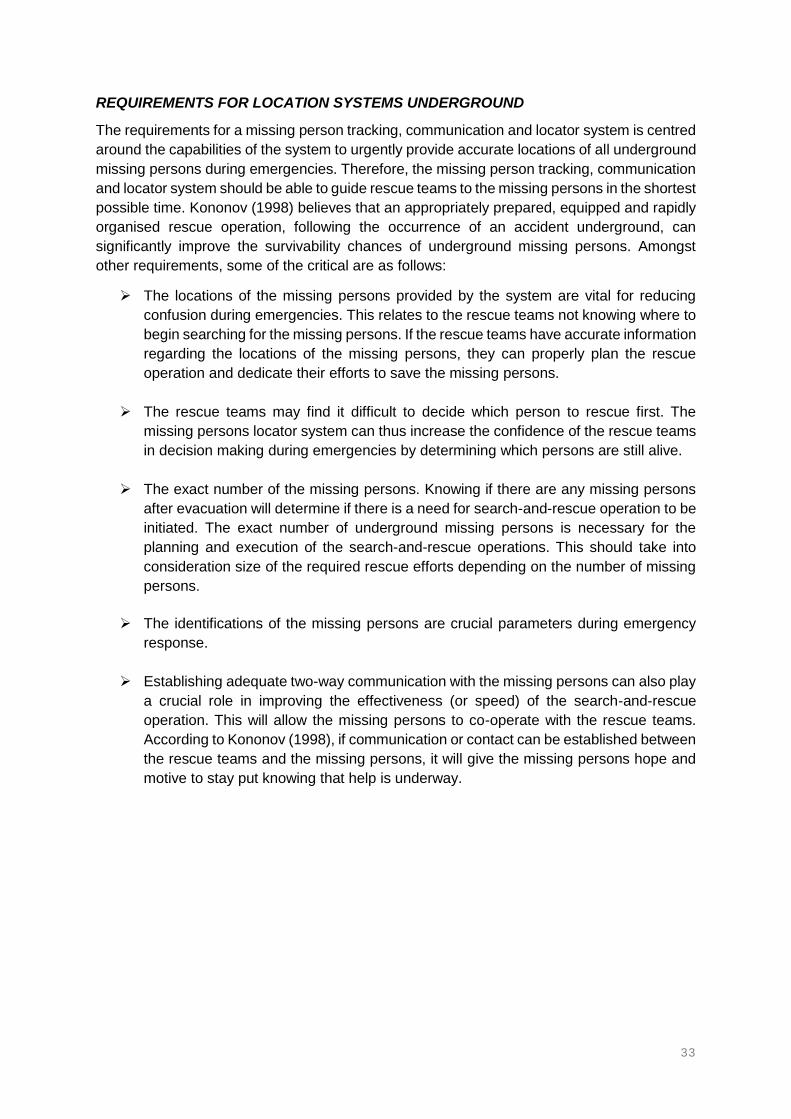
33
REQUIREMENTS FOR LOCATION SYSTEMS UNDERGROUND
The requirements for a missing person tracking, communication and locator system is centred
around the capabilities of the system to urgently provide accurate locations of all underground
missing persons during emergencies. Therefore, the missing person tracking, communication
and locator system should be able to guide rescue teams to the missing persons in the shortest
possible time. Kononov (1998) believes that an appropriately prepared, equipped and rapidly
organised rescue operation, following the occurrence of an accident underground, can
significantly improve the survivability chances of underground missing persons. Amongst
other requirements, some of the critical are as follows:
The locations of the missing persons provided by the system are vital for reducing
confusion during emergencies. This relates to the rescue teams not knowing where to
begin searching for the missing persons. If the rescue teams have accurate information
regarding the locations of the missing persons, they can properly plan the rescue
operation and dedicate their efforts to save the missing persons.
The rescue teams may find it difficult to decide which person to rescue first. The
missing persons locator system can thus increase the confidence of the rescue teams
in decision making during emergencies by determining which persons are still alive.
The exact number of the missing persons. Knowing if there are any missing persons
after evacuation will determine if there is a need for search-and-rescue operation to be
initiated. The exact number of underground missing persons is necessary for the
planning and execution of the search-and-rescue operations. This should take into
consideration size of the required rescue efforts depending on the number of missing
persons.
The identifications of the missing persons are crucial parameters during emergency
response.
Establishing adequate two-way communication with the missing persons can also play
a crucial role in improving the effectiveness (or speed) of the search-and-rescue
operation. This will allow the missing persons to co-operate with the rescue teams.
According to Kononov (1998), if communication or contact can be established between
the rescue teams and the missing persons, it will give the missing persons hope and
motive to stay put knowing that help is underway.

34
EFFECTS OF EMERGENCY RESPONSE
The success of search-and-rescue operations is heavily dependent on emergency response,
emergency escape and reactive search-and-rescue operations. Kowalski-Trakofler et al
(2010) discovered that factors such as mine emergency planning, communication, training
and decision-making are crucial during the first moments of underground mine emergency
responses. However, these factors may not necessarily fast track the search-and-rescue
operations if the locations of missing persons are unknown. Jansky et al (2016) discusses
factors that can influence the behaviour of rescue teams during emergency response.
Kowalski-Trakofler and Vaught (2012) investigated the factors that can influence mine
emergency evacuation and some factors that can improve mine emergency response and
preparedness. These factors include planning, psychological-support, decision-making and
action-plan. While the preparedness of mine emergency response is fundamental, adequate
information regarding the people remaining underground is critical and of utmost importance
during emergencies. This information can be obtained from the missing person tracking, two-
way communication and locator system. The system can provide the locations of mine
personnel affected by an accident and rescue teams can attend to the persons as quickly as
possible.
BENEFITS OF QUICK RESPONSE DURING EMERGENCIES
According to the Mining Safety (2018), it is of utmost importance that the miners who have
been affected by an accident be provided with the best possible assistance and emergency
medical treatment. The medical treatment must be provided within the Golden Hour in order
to stand a chance of surviving. The Golden Hour concept stipulates that the chances of
survival become slimmer if medical care is not provided within the first hour after an accident
(Lerner and Moscati, 2001; Bledsoe, 2002). Therefore, the missing persons stand a good
chance of surviving if located and evacuated in the shortest possible time. Entrapments mostly
occur if the miners fail to evacuate or escape (Yarkan et al., 2009).
Reaching the missing persons in the shortest possible time may save the lives of the trapped
miners who survived the accident. This will allow rescue teams to provide medical care to the
survivors as soon as possible. Medical emergency response can play a significant role in
saving the lives of missing miners who may be injured. The missing persons must therefore
be located in the shortest possible time. This is because the missing persons could still be
alive and unharmed, slightly injured or severely injured. Obtaining the locations of the missing
persons will significantly reduce the amount of time spent searching, and subsequently quicker
rendering medical assistant to the missing miners. The benefits of rescuing missing persons
include:
Reduction in number of fatalities in the industry
Reduction is lost production time
Avoid affecting the reputation of the mining industry and the state
Trust from the surrounding communities
Shareholder confidence

35
FAILED AND/OR PROLONGED SEARCH-AND-RESCUE OPERATIONS
Prolonged search-and-rescue operations are most likely to result in fatalities. The lengthy
search-and-rescue operations will cause an increase in the number of fatalities. Failure to
locate the missing persons will result in an increase in the number of fatalities. It was realised
from the past accidents that miners can survive the initial event but are fatally injured from the
lack of emergency medical assistance while trapped underground. When miners go missing
underground, mining operations will be suspended in that shaft until such time that all the
missing persons have been found and retrieved from underground. This is regardless whether
the persons are still alive or deceased. Furthermore, the operations remain suspended
regardless of the number of people remaining unaccounted for underground. Therefore,
accidents involving missing persons in underground mines do not only affect the safety
statistics, but also the profitability of the mine.
The issuing of Section 54 stoppages has been found to be a financial burden to mines (Gloy,
2014; Miningmx, 2014; Miningmx, 2015). As a result of prolonged search-and-rescue
operations, mines will remain closed for a longer period and may be issued with the Section
54. As a result, the mines can be subjected to financial losses due to lost production time while
the search-and-rescue operation is ongoing. Mining operations can lose millions of Rands
during the suspension of operations, while search-and-rescue operations are underway.
Failure to locate the missing persons may result in failure to even recover the bodies of the
missing miners. Being able to recover the bodies will give the families of the missing persons
closure. This can cause the mine to shutdown permanently. The closure of mines has an
impact on the surrounding communities in terms of job opportunities. This can also result in
job losses if the mine cannot be reopened. Job losses will affect the families, friends and
colleagues of the miners who were working for that particular mine. Failure to locate and
rescue the missing miners does not only affect the communities, but also the reputation of the
country and the mining industry.
MISSING PERSONS IN OTHER INDUSTRIES
People going missing in confined spaces and unknown locations does not only occur in
underground mining environments, but also on surface environments. This happens as a
result of natural disasters such as earthquakes and collapsed buildings in which people were
present (Huo et al., 2011; Chen et al., 2000; Zade and Badnerkar, 2011). These events often
result in the people trapped and lost beneath rubble material such that the human eye cannot
detect them as quickly as possible. Dogs, optical devices, acoustic life detectors and robots
are some of the common existing and applicable methods used for detecting people trapped
in earthquake rubble and buried in collapsed buildings (Zade and Badnerkar, 2011).
The trapped people are likely to be injured during these events and thus require emergency
medical response. However, the medical assistance can only be provided once the trapped
persons have been located. Adults uninjured during an event, with a supply of air and water,
has a high probability of survival, but only if they are recovered within 72 hours since the
entrapment occurred (Huo et al., 2011). Other studies have shown that people who survived
entrapments were recovered within 48 hours, while the survival chances reduced rapidly after
72 hours and become very slim after 120 hours of being trapped (Huo et al., 2011).
.

36
1.7. PROBLEM STATEMENT
The failure and/or delay in search-and-rescue operations is often due to the lack of the
necessary positioning information that can be useful in locating missing persons – how many
persons are lost or trapped underground; where these persons are located; how many are
they; and how to prioritise rescue efforts over recovery efforts. This information can and should
be obtained from a missing person tracking, two-way communication and locator system that
can urgently determine the whereabouts of the missing persons. In this study, the need and
value these systems in the mining industry have been emphasised. In order to the save lives
of the missing persons, the system should be able to guide rescue teams to the locations of
the missing persons as quickly as possible. A wide variety of systems, technologies and
search devices that are characterised by different functions, capabilities and limitations are
commercially available worldwide. The study exposes the availability of these systems to the
mining industry. However, it was found from previous investigations that these systems are
challenging to implement and operate in underground mines. As such, a slow embracement
of these systems in the industry has been realised. This, therefore necessitated the need into
research to define a suitable and fit for purpose system for the mining industry. The main aim
of this study was therefore to investigate and propose a much more suitable and fit for purpose
missing person locator system for underground mining environments.

37
1.8. OBJECTIVES AND METHODOLOGIES
The objectives and methodologies for the study can be seen in Table 3. The methodology is
further discussed in more detail in Chapter 3.
Table 3: Objectives and Methodologies for the study
OBJECTIVES METHODOLOGY
1. Identify and investigate mining
accidents that resulted in
persons going missing
underground mines in South
Africa and internationally and
define going missing scenarios.
Past accidents, in South Africa and internationally, that resulted in
persons going missing underground were identified and
investigated. From the study of the accidents, the factors that
contributed to persons going missing underground were identified.
These accidents were then used to formulate a list of scenarios in
which persons can go missing underground after an accident.
2. Evaluate the availability and
utilisation of systems,
technologies and devices
(including their functions,
capabilities and limitations) that
can track and locate missing
persons in underground mines.
A literature review was conducted to identify systems, technologies
and devices that have the capabilities to track and detect the
locations of missing persons in underground mines. Apart from the
currently available and used systems, the literature review was
conducted to also identify systems, technologies and devices that
are under development as well as systems and technologies that
can be adopted in the mining industry. Systems, technologies and
devices used in relevant industries, but with potential application to
track and locate missing persons in the mining industry were also
identified.
3. Evaluate the suitability of the
identified systems in (2)
against the going missing
scenarios identified and
investigated in (1).
Use the list going missing scenarios to evaluate the systems that
can be suitable and those that may be unsuitable to track and
locate missing persons in that scenario. Use a matrix diagram for
the evaluation exercise of the systems against the going missing
scenarios.
4. Derive system user
requirements of an ideal
system and use these system
user requirements to evaluate
the suitability of the identified
systems.
Use the information and findings obtained from (1) – (3) to develop
and define system user requirements that can be used to evaluate
the suitability of potential missing person tracking and locator
systems that become commercially available in the market. The
system user requirements were developed according to
specifications of an ideal missing person tracking and locator
system suitable for underground mining. A list of critical questions
related to emergency scenario were used as part of the user
requirements development.
5. Evaluate the application of the
identified systems into the
different underground travelling
and working areas.
The active underground areas where people are often expected to
work and travel were identified. The identified systems were then
evaluated according to these areas. This was done to determine
the systems that can work in the different areas of the mine where
people are expected to be present in case an accident happens.

38
OBJECTIVES METHODOLOGY
6. Evaluate the possibility and
impact of integrating different
systems to function as a single
system.
The outcomes of (1) to (5) were used to assess the possibility of
improving suitability by combining different systems. The
capabilities and/or advantages of the different systems were
combined to form one system. This was also done to minimise the
limitations of the systems by benefiting from the different systems.
7. Make conclusions on the
findings of the study.
Conclusions were made based on the findings of the study.
8. Make recommendations on the
findings of the study.
Recommendations were made based on the findings and
conclusions of the study.
9. Identify areas the will require
further studies beyond this
study.
Suggestion for further future studies based on the new research
stemming from, but did not form part of this study were made,
based on the findings and recommendations of the study.

39
CHAPTER 1: LIST OF REFERENCES
ABC News. (2006). Mine rescue operation ‘slower than expected’. Available online: https://web.archive.org/web/20060505162352/http://www.abc.net.au/news/newsitems/200605/s1631149.htm
ABC News. (2006). Mine rescuers within metres. Available online: https://web.archive.org/web/20071117044706/http://www.abc.net.au/news/newsitems/200605/s1632287.htm
Aksogan, P., Bayram, D. and Ciftci, I. (2014). Soma coal mine disaster information report.
http://priceofoil.org/content/uploads/2014/06/Soma-Coal-Mine-Disaster-Report-GPMED.pdf
ANN7 News. (2016). Trapped Lily Mine workers ‘dead’. http://www.ann7.com/trapped-lily-mine-workers-dead/
Antin, D. (2013). The South African mining sector: An industry at a crossroads. Economy Report South Africa. Available online: https://southafrica.hss.de/fileadmin/user_upload/Projects_HSS/South_Africa/170911_Migration/Mining_Report_Final_Dec_2013.pdf
Bandyopadhyay, L.K., Chaulya, S.K. and Mishra, P.K. (2010). Wireless communication in underground mines: RFID-based sensor networking. Springer, New York, USA.
BBC News. (2009). Toll climbs in China mine blast. Available online: http://news.bbc.co.uk/2/hi/asia-pacific/7904122.stm
BBC News. (2010). At least 21 miners killed in China colliery blast. Available online: http://news.bbc.co.uk/2/hi/asia-pacific/8681855.stm
BBC News. (2010). China flooded mine traps dozens in Inner Mongolia. Available online: http://news.bbc.co.uk/2/hi/asia-pacific/8544682.stm
BBC News. (2010). Hundreds join Chinese mine rescue effort. Available online: http://news.bbc.co.uk/2/hi/asia-pacific/8591547.stm
BBC News. (2010). Toll rises in Russia mine blast. Available online: http://news.bbc.co.uk/2/hi/europe/8671702.stm
BBC News. (2014). As it happened: Turkey mine disaster. Available online: http://www.bbc.com/news/world-europe-27406195
BBC News. (2014). Turkey mine: Hopes fade for 18 trapped coal miners. Available online: http://www.bbc.com/news/world-europe-29816242
BBC News. (2015). South Africa Harmony Gold mine fire to be probed. http://www.bbc.com/news/world-africa-31586104
BBC News. (2015). Ukraine coal mine: Dozens feared dead in Zasyadko gas blast. Available online: http://www.bbc.com/news/world-europe-31725243
BBC News. (2016). Russian mine accident leaves 36 dead. Available online: http://www.bbc.com/news/world-europe-35681242
BBC News. (2016). Trapped South Africa mine workers 'still alive'. http://www.bbc.com/news/world-africa-35520980
Blank, V. G., Diderichsen, F., and Andersson, R. 1996. Technological development and occupational accidents as a conditional relationship: A study of over eighty years in the Swedish Mining industry. Journal of Safety Research, 27(3), 137−146

40
Bledsoe, B.E. (2002). The Golden Hour: fact or fiction? Emergency Medical Services, 31(6), 105.
Bonsu, J. (2013). A systemic study of mining accident causality: an analysis of 91 mining accidents from a platinum mine in South Africa. Master’s Thesis, University of Cape Town.
Bonsu, J., van Dyk, W., Franzidis, J-P., Petersen, F. and Isafiade, A. (2017). A system approach to mining safety: an application of the Swiss Cheese Model. Journal of the Southern African Institute of Mining and Metallurgy, 116(8), 777 – 784.
Business Day. (2016). Trapped Rustenburg miner’s body found. https://www.businesslive.co.za/bd/companies/mining/2016-05-20-trapped-rustenburg-miners-body-found/
Business Report. (2016). SA mine deaths rise after years of improving safety. Available online: https://www.iol.co.za/business-report/economy/sa-mine-deaths-rise-after-years-of-improving-safety-2063416
Candemir, Y. (2014). Turkey recovers last bodies from flooded Ermenek coal mine. The Wall
Street Journal. Available online: https://www.wsj.com/articles/turkey-finds-last-bodies-from-
flooded-ermenek-coal-mine-1417697084
Carreno, J.P., de Silva, L.S., de Almeida Neves, S.O., Aguayo, L., Braga, A.J., Barreto, A.N. and Garcia, L.G.U. (2016). Through-The-Earth (TTE) communications for underground mines. Journal of Communications and Information systems, 31(1), 164 – 176.
Cawley, J.C. 2003. Electrical accidents in the mining industry. IEEE Transaction On Industry Applications, 39(6), 1570 – 1577.
CBS News. (2010). Flood traps 153 Chinese miners underground. Available online: https://www.cbsnews.com/news/flood-traps-153-chinese-miners-underground/
Chamber of Mines. (2016). Safety in the mining industry: Performance at a glance. Chamber of Mines of South Africa. Available online: https://www.mineralscouncil.org.za/industry-news/publications
Chamber of Mines. (2017). Safety in the mining industry: Performance at a glance. Chamber of Mines of South Africa. Available online: https://www.mineralscouncil.org.za/industry-news/publications
Chen, K-M., Huang, Y., Zhang, J. and Norman, A. (2000). Microwave life-detection systems for searching human subjects under earthquake rubble or behind barrier. IEEE Transactions on Biomedical Engineering, 27(1), 105 – 114.
China Daily. (2009). Coal mine toll at 44; 35 still trapped. Available online: http://www.chinadaily.com.cn/china/2009-09/11/content_8679090.htm
China Daily. (2010). 24 miners trapped after S.W. China coal-gas outburst. Available online: http://www.chinadaily.com.cn/2010-05/14/content_9847231.htm
CNN News. (2006). Drill readied for trapped miners. Available online: https://web.archive.org/web/20060505040721/http://edition.cnn.com/2006/WORLD/asiapcf/05/02/australia.miners.ap/
CNN News. (2010). 52 dead in Russian mine blasts. Available online: http://edition.cnn.com/2010/WORLD/europe/05/11/russia.mine.blast/index.html
CNN News. (2010). Bodies of 28 trapped Turkish miners found. Available online: http://edition.cnn.com/2010/WORLD/europe/05/20/turkey.miners/

41
CNN News. (2015). Officials: 33 bodies recovered from eastern Ukraine mine disaster. Available online: http://edition.cnn.com/2015/03/04/europe/ukraine-miners-trapped/index.html
CNN News. (2016). Russian mine disaster death toll hits 36 after explosion during failed rescue effort. Available online: http://edition.cnn.com/2016/02/28/europe/russia-mine-explosions-severnaya/index.html
CRIEnglish. (2012). Chinese rescuers race to save trapped miners. Available online: http://english.cri.cn/6909/2012/08/30/2724s719740.htm
Daily Mail. (2015). Nearly 500 South African miners escape after fire. http://www.dailymail.co.uk/wires/afp/article-2964145/Nearly-500-workers-trapped-fire-S-Africa-gold-mine.html
Damiano, N., Homce, G. and Jacksha, R. 2014. A Review of underground coal mine emergency communications and tracking system installations. CoalAge. Available online: http://www.coalage.com/features/4078-a-review-of-underground-coal-mine-emergency-communications-and-tracking-system-installations.html#.WlxlJ6iWaM8
Douglas, A.D. (2014). Status of communication and tracking technologies in underground coal mines. Master’s Thesis, University of Kentucky.
Eiter, B.M., Kosmoski, C.L., and Connor, B.P. (2016). Defining hazard from the mine worker’s perspective. Mining Engineering Author Manuscript, 68(11), 50 – 54.
eNCA. (2013). Mine collapse traps four. https://www.enca.com/south-africa/mine-collapse-traps-four
eNCA. (2013). Trapped West Rand miners freed. https://www.enca.com/south-africa/trapped-west-rand-miners-freed
eNCA. (2014). Eight Harmony miners die underground. https://www.enca.com/south-africa/eight-die-after-harmony-fire
eNCA. (2015). Hundreds trapped underground following fire at Harmony gold mine. https://www.enca.com/south-africa/underground-fire-contained-harmony-golds-kusasalethu-mine
eNCA. (2017). Miners trapped after seismic incident at Tau Lekoa mine. https://www.enca.com/south-africa/miners-trapped-after-seismic-incident-at-tau-kekoa-mine
eNCA. (2017). Rescue operation continues for trapped Kusasalethu miners. https://www.enca.com/south-africa/rescue-operation-continues-for-trapped-kusasalethu-miners
eNCA. (2017). Search for two miners at Kusasalethu difficult. https://www.enca.com/south-africa/search-for-two-trapped-miners-at-kusasalethu-continues
Euro News. (2010). China mine blast leaves 21 dead. Available online: http://www.euronews.com/2010/05/14/china-mine-blast-leaves-21-dead
Eyewitness News. (2016). Retrieving bodies of lily mine workers unlikely. http://ewn.co.za/2017/02/08/retrieving-bodies-of-lily-miner-workers-unlikely-parliament-hears
Eyewitness News. (2017). Harmony gold to hold memorial service for dead Kusasalethu miners. Available online: http://ewn.co.za/2017/08/31/harmony-gold-to-hold-memorial-service-for-dead-kusasalethu-miners
Eyewitness News. (2017). NW premier to visit Tau Lekoa mine after death of miners. http://ewn.co.za/2017/07/24/nw-premier-to-visit-tau-lekoa-mine-after-death-of-miners

42
Fedderke, F. and Pirouz, J. (2002). The role of mining in the South African economy. South African Journal of Economic and Management Sciences, 5(1), 1 – 34.
Fiscor, S. (2008). Underground communications and tracking systems update. Coalage. Available online: https://products.rfsworld.com/userfiles/pdf/coal_age_reprint_jan08.pdf
Forooshani, A.E., Bashir, S., Michelson, D.G. and Noghanian, S. (2013). A survey of wireless communications and propagation modelling in underground mines. IEEE Communications Surveys and Tutorials, 15(4), 1524 – 1545.
Frankel, P.H. (2013). Between the rainbows and the rain: Marikana, migration, mining, and the crisis of modern South Africa. Google Books. Available online: http://www.africanbookscollective.com/books/between-the-rainbows-and-the-rain
Ganguli, R., Beer, S. and Watson, M. (2011). Mine communications, monitoring, and control: Chapter 9.3. Society for Mining, Metallurgy, and Explorations, Inc. Google Books. Available online: https://books.google.co.za/books?id=5uq-kdfHLWUC&pg=PA717&lpg=PA717&dq=Mine+communications,+monitoring,+and+control:+Chapter+9.3&source=bl&ots=wprnzprZXN&sig=ACfU3U2JbD6IcEVbzMo1yCPxY05mEQaVwA&hl=en&sa=X&ved=2ahUKEwjq9rrN55PgAhVSuHEKHT-pAmsQ6AEwAHoECAcQAQ#v=onepage&q=Mine%20communications%2C%20monitoring%2C%20and%20control%3A%20Chapter%209.3&f=false
Gloy, M. (2014). The use of Section 54 stoppage orders in terms of the Mine Health and Safety Act. Magister Legum Mini-dissertation.
Griffith, C. (2017). Launch of the Mining Resilience Research Centre (MRRC). Department of Mining Engineering, University of Pretoria. Available online: http://www.up.ac.za/en/news/post_2489184-mining-resilience-research-centre-established-at-up https://www.youtube.com/watch?v=U9vRtbzNv3w&t=2722s
Grooves, W.A., Kecojevic, V.J. and Komljenovic, D. (2007). Analysis of fatalities and injuries involving mining equipment. Journal of Safety Research, 38(4), 461 – 470.
Harmony Gold. (2014). Fire underground at Doornkop mine. https://www.harmony.co.za/investors/news-and-events/company-announcements-2/announcements-2014/770-fire-underground-at-doornkop-mine
Harmony Gold. (2015). Underground fire at Kusasalethu gold mine: rescue operation in progress. https://www.harmony.co.za/investors/news-and-events/company-announcements-2/announcements-2015/838-underground-fire-at-kusasalethu-gold-mine-rescue-operation-in-progress
Health and Safety Executive. (2011). Gleison mine incident. A factual report by the Health and Safety Executive. http://www.hse.gov.uk/mining/gleison-mine-incident-report.pdf
Huo, R., Agapiou, A., Bocos-Bintintan, V., Brown, L.J., Burns, C., Creaser, C.S., Devenport, N.A., Gao-Lau, B., Guallar-Hoyas, C., Hildebrand, L., Malkar, A., Martin, H.J., Moll, V.H., Patel, P., Ratiu, A., Reynold, J.C., Sielemann, S., Sledzynski, R., Statheropoulos, M., Turner, M.A., Vautz, W., Wright, V.E. and Thomas, C.L.P. (2011). The trapped human experiment. Journal of Breath Research, 5(4). Available online: https://www.ncbi.nlm.nih.gov/pubmed/21908906
Impala Platinum. (2016). http://www.implats.co.za/
IndustriALL. (2015). 9 miners dead and 23 missing after explosion in Ukrainian coal mine. Available online: http://www.industriall-union.org/9-miners-dead-and-23-missing-after-explosion-in-ukrainian-coal-mine

43
IOL News. (2013). Four miners trapped on West Rand. https://www.iol.co.za/business-report/companies/four-miners-trapped-on-west-rand-1611736
IOL News. (2014). Escape from mine shaft hell. https://www.iol.co.za/capetimes/news/escape-from-mine-shaft-hell-1642642
IOL News. (2017). Memorial service for trapped Lily Mine workers. https://www.iol.co.za/news/south-africa/mpumalanga/memorial-service-for-trapped-lily-mine-workers-7574520
IOL News. (2017). NUM saddened by death of mineworkers at Tau Lekoa Mine. https://www.iol.co.za/news/num-saddened-by-death-of-mineworkers-at-tau-lekoa-mine-10445903
IOL News. (2017). Trapped Kusasalethu miners’ cry for help. Available online: https://www.iol.co.za/news/south-africa/gauteng/trapped-kusasalethu-miners-cry-for-help-10982256
Jacinto, C. and Soares, C. G. 2008. The added value of the new ESAW/Eurostat variables in accident analysis in the mining and quarrying industry. Journal of Safety Research, 39, 631–644.
Jansky, J.H., Kowalky-Trakofler, K.M., Brnich, M.J. and Vaught, C. (2016). Factors influencing mine rescue team behaviors. Journal of Emergency Management, 14(1).
Kane-Berman, J. (2017). Mining in SA: Then, now, and into the future – IRR. Politicsweb. Available online: http://www.politicsweb.co.za/archive/mining-in-sa-then-now-and-into-the-future--irr
Kantor, B. (2013). How important is mining to the SA economy. It depends on how you measure it. A Blog on the South African Economy and its Financial Markets, ZAeconomist. Available online: http://www.zaeconomist.com/sa-economy/how-important-is-mining-to-the-sa-economy-it-depends-on-how-you-measure-it/
Kecojevic, V., Komljenovic, D., Groves, W. and Radomsky, M. (2007). An analysis of equipment-related fatal accidents in U.S. mining operations: 1995–2005. Safety Science, 45(8), 864 – 874.
Kemljenovic, D., Groves, W. and Kecojevic, V. (2008). Injuries in U.S. mining operations—a preliminary risk analysis. Safety Science, 46(5), 792–801.
Kononov, V.A. (1998). Develop a trapped miner location system and an adequate rescue strategy and associated technologies. GEN 502 Final Project Report, CSIR Division of Mining Technology.
Kowalski-Trakofler, K.M. and Vaught, C. (2012). Psycho-social issues in mine emergencies: The impact on the individual, the organization and the community. Minerals, 2, 129 – 168.
Kowalski-Trakofler, K.M., Vaught, C., Brnich, M.J. and Jansky, J.H. (2010). A study of first moments in underground mine emergency response. Available online: https://www.cdc.gov/niosh/mining/UserFiles/works/pdfs/asofm.pdf
Kumar, A., Chaulya, S.K., Kumar, S. and Bandyopadhyay, L.K. (2003). Trapped miners detection, location and communication system. Minetech, 24(6), 1-13.
KyivPost. (2015). Death toll rises to 34 in Zasiadko coal mine disaster. Available online:
https://www.kyivpost.com/article/content/ukraine-politics/death-toll-rises-to-34-in-zasiadko-
coal-mine-disaster-382782.html

44
Laliberte, P. (2009). Summary study of underground communications technologies. Final Project Report CANMET-MMSL. Available online: http://www.wvminesafety.org/PDFs/UndergroundCommunicationsReport.pdf
Lerner, E.B. and Moscati, R.M. (2001). The Golden Hour: Scientific Fact or Medical “Urban Legend”. Academic Emergency Medicine, 8(7), 758 – 760.
Los Angeles Times. (2016). Methane explosions in Russian coal mine kill 36; cause dispute. Available online: http://www.latimes.com/world/europe/la-fg-russia-mine-36-20160228-story.html
Lowvelder. (2016). Lily mine accident. Available online: https://lowvelder.co.za/314520/lily-mine-hope-vanishes-as-days-go-by/
Mail & Guardian. (2007). Mining in SA: ‘Deep, dark and dangerous’. Available online: https://mg.co.za/article/2007-10-11-mining-in-sa-deep-dark-and-dangerous
Mail & Guardian. (2014). Eight miners' bodies recovered at Harmony after fire. https://mg.co.za/article/2014-02-06-eight-miners-bodies-recovered-at-harmony-after-fire-report
Mail & Guardian. (2016). Lily Mine rescue hopes dashed as AfroCan withdraws and Vantage plans to sue. https://mg.co.za/article/2016-07-05-lily-mine-rescue-hopes-dashed-as-afrocan-withdraws-and-vantage-plans-to-sue
Mail & Guardian. (2017). Search and rescue continues for trapped Impala Platinum mine workers. https://mg.co.za/article/2016-05-18-search-and-rescue-continues-for-trapped-mine-workers
Masia, U. and Pienaar, J. (2011). Unravelling safety compliance in the mining industry: examining the role of work stress, job insecurity, satisfaction and commitment as antecedents. SA Journal of Industrial Psychology, 37(1), 937 – 947.
McAteer, J.D., Beall, K., Beck, J.A., McGinley, P.C., Monforton, C., Roberts, D.C., Spence,
B. and Weise, S. (2011). Upper Big Branch: The April5, 2010, explosion: a failure of basic
coal mine safety practices. Report to the Governor. Available online:
https://www.npr.org/documents/2011/may/giip-massey-report.pdf
Middle East Eye. (2014). Turkish rescuers struggle to reach trapped miners. Available online: http://www.middleeasteye.net/news/turkish-rescuers-struggle-reach-trapped-miners-1346563669
Mine Health and Safety Administration. (2006). Mine Improvement and New Emergency Response Act of 2006. United States Public Laws. Available online: https://arlweb.msha.gov/MinerAct/2006mineract.pdf
Mine Health and Safety Council. (2014). Annual Report 2014/2015. Available online: http://www.mhsc.org.za/sites/default/files/MHSC%20ANNUAL%20REPORT%202014%202015%20.pdf
Mine Health and Safety Council. (2014). Every mine worker returning from work unharmed every day. Striving for zero harm. Available online: http://www.mhsc.org.za/sites/default/files/2014%20OHS%20Summit%20Milestones.pdf
Mine Health and Safety Council. (2017). Available online: http://www.mhsc.org.za/
Mine Safety and Health Administration. (2014). Upper Big Branch mine-south, Performance coal company. Available online: https://www.msha.gov/data-reports/reports/Upper%20Big%20Branch%20Mine-South%2C%20Performance%20Coal%20Company

45
Mining Review Africa. (2013). Trapped mine workers freed. https://www.miningreview.com/news/trapped-mine-workers-freed/
Mining Review Africa. (2016). Lily mine: Rescue operations suspended indefinitely. https://www.miningreview.com/news/lily-mine-rescue-operations-suspended-indefinitely/
Mining Safety. (2017). Emergency medical response and mining safety. Available online: www.miningsafety.co.za
Mining Technology. (2017). Tremor kills miners at Tau Lekoa gold mine in Orkney, South Africa. http://www.mining-technology.com/news/newsseismic-incident-kills-four-people-at-tau-lekoa-gold-mine-in-orkney-south-africa-5881159
Mining Weekly. (2017). Bodies of two last remaining trapped Kusasalethu miners recovered. Available online: http://www.miningweekly.com/article/bodies-of-two-last-remaining-trapped-kusasalethu-miners-recovered-2017-08-31
Mining Weekly. (2017). Lily mine secures funding and will resume search in September. http://www.miningweekly.com/article/lily-mine-secures-funding-and-will-resume-search-in-september-2017-06-09
MINING.com. (2013). 300 coal miners barricade themselves inside Turkish mine. Available online: http://www.mining.com/300-coal-miners-barricade-themselves-inside-turkish-coal-mine-38854/
MINING.com. (2014). At least 18 Turkish miners trapped in coal mine after collapse. Available online: http://www.mining.com/at-least-23-turkish-miners-trapped-in-coal-mine-after-collapse-35062/
Miningmx. (2015). Safety stoppages cost SA mining R13.6bn. Available online: http://www.miningmx.com/news/off-the-wires/13932-safety-stoppages-cost-sa-mining-r13-6bn/
Miningmx. (2016). Miners missing at Implats’ Rustenburg after ‘fall of ground’. http://www.miningmx.com/news/platinum/27271-miners-missing-at-implats-rustenburg-after-fall-of-ground/
Miningmx. (2016). Section 54s cost SA mines R4.8bn in 2015, and 2016 may be worse. Available online: http://www.miningmx.com/opinion/columnists/27866-stoppages-lop-r4-8bn-off-2015-revenue-2016-worse/
Miningmx. (2017). Death of third mineworker confirmed at Harmony’s Kusasalethu mine. Available online: https://www.miningmx.com/news/gold/30334-three-miners-still-missing-harmonys-kusasalethu-mine/
Mitchell, R. J., Driscoll T. R., and Harrison J.E. 1998. Traumatic work-related fatalities involving mining in Australia. Safety Science, 29(2), 107-123.
Moridi, M.A., Kawamura, Y., Sharifzadeh, M., Chanda, E.K. and Jang, H. (2014). An investigation of underground monitoring and communication system based on radio waves attenuation using ZigBee. Tunnelling and Underground Space Technology, 43, 362 – 369.
Msiza, D. (2014). The road to zero harm new milestones. Mine Occupational Health and Safety SMMIT Presentation. Available online: https://www.mhsc.org.za/sites/default/files/Mr%20Msiza%202014%20Milestones_0.pdf
Murphy, J.N. and Parkinson, H.E. (1978). Underground mine communication. Proceedings of the IEEE, 66(1), 26 – 50.
National Institute for Occupational Safety and Health. (2013). Tutorial on wireless communications and electronic tracking, Part 2: Advanced. Available online:

46
https://www.cdc.gov/niosh/mining/content/emergencymanagementandresponse/commtracking/advcommtrackingtutorial1.html
News.com.au. (2006). Fears for miners caught in rockfall. Available online: https://web.archive.org/web/20070814123629/http://www.news.com.au/story/0%2C10117%2C18932778-1702%2C00.html
News24. (2013). Trapped Amplats miners found dead. https://www.fin24.com/Companies/Mining/Trapped-Amplats-miners-found-dead-20130724
News24. (2015). All 486 trapped mineworkers rescued - as it happened. https://www.fin24.com/Companies/Mining/LIVE-184-of-almost-500-trapped-mineworkers-rescued-20150222
News24. (2016). Unions unhappy as Lily Mine goes into business rescue. https://www.fin24.com/Economy/Labour/News/unions-unhappy-as-lily-mine-goes-into-business-rescue-20160411
News24. (2017). Bodies of last two missing Kusasalethu miners recovered. Available online: http://www.news24.com/SouthAfrica/News/bodies-of-last-two-kusasalethu-miners-recovered-20170831
News24. (2017). Desperate bid to save trapped men at Rustenburg mine. http://www.news24.com/SouthAfrica/News/desperate-bid-to-save-trapped-men-at-rustenburg-mine-20160518
Nutter, R.S. (2007). Underground coal mine communications and tracking status SAGO plus one year. Industrial Applications Conference IEEE. Available online: https://ieeexplore.ieee.org/document/4348064
Pajaanen, S.K., Tran, T.T. and Dubreuil, P. (2012). Case study: Underground real-time locating system selection criteria. Available online: http://www.bestech.com/download/case-study-underground-real-time-locating-system-selection-criteria-2012/
Patri, A., Nayak, A. and Jayanthu, S. (2013). Wireless communication systems for underground mines – A critical appraisal. International Journal of Engineering trends and Technology (IJETT), 4(7), 3149 – 3153.
People’s Daily. (2010). Rescue efforts stopped for 31 trapped miners in N China. Available online: http://en.people.cn/90001/90776/90882/6919739.html
Primedia Broadcasting: Radio 702. (2017). 'Everything was done to try rescue trapped Lily Mine workers'. http://www.702.co.za/articles/243625/everything-was-done-to-try-rescue-trapped-lily-mine-workers
Probst, T.M. and Brubaker, L. (2001). The effects of job security on employee safety outcomes: Cross-section and longitudinal explorations. Journal of Occupational Health Psychology, 6(2), 139 – 159.
PwC South Africa. (2015). SA’s mining industry sees steep decline in financial performance impacted by a slump in commodity prices and increased cost pressures. Available online: http://www.pwc.co.za/en/press-room/sa_s-mining-industry-sees-steep-decline-in-financial-performance.html
Ranjan, A. and Sahu, H.B. (2014). Communication challenges in underground mines. Search and research, 5(2), 23 – 29.
Reuters. (2010). Flood in new China coal mine traps 123 miners. Available online: https://www.reuters.com/article/us-china-mine/flood-in-new-china-coal-mine-traps-123-miners-idUSTRE62R0VK20100328
http://www.news24.com/SouthAfrica/News/desperate-bid-to-save-trapped-men-at-rustenburg-mine-20160518

47
Reuters. (2012). At least 26 killed, 21 missing in Chinese mine blast: Xinhua. Available online: https://www.reuters.com/article/us-china-mine/at-least-26-killed-21-missing-in-chinese-mine-blast-xinhua-idUSBRE87T0S520120830
Reuters. (2014). At least eight dead in South African gold mine accident. http://www.reuters.com/article/us-safrica-miners/at-least-eight-dead-in-south-african-gold-mine-accident-idUSBREA1506A20140206
Reuters. (2014). Hopes dim for 18 workers trapped in Turkish mine. Available online: https://www.reuters.com/article/us-turkey-mine-collapse/hopes-dim-for-18-workers-trapped-in-turkish-mine-idUSKBN0IH18520141028
Ruff, T., Coleman, P. and Martini L. 2011. Machine-related injuries in the US mining industry and priorities for safety research. International Journal of Injury Control and Safety Promotion, 18(1), 11 – 20.
Saleh, J.H. and Cummings, A.M. (2011). Safety in the mining industry and the unfinished legacy of mining accidents: Safety levers and defense-in-depth for addressing mining hazards. Safety Science Journal, 49, 764 – 777.
Schafrik, S.J., Dietrich, C. and Harwood, C. (2013). Geolocation for underground coal mining applications: classification of systems and limitations. SME Mining Engineering Online, 66(4). Available online: http://me.smenet.org/abstract.cfm?preview=1&articleID=4766&page=22
Schiffbauer, W.H. and Mowrey, G.L. (2006). Preliminary assessment of communication systems for underground mines for normal and emergency operations. Available online: http://www.wvminesafety.org/PDFs/communications/Additional%20Documents/Prelim_Assessment_of_Communications.pdf
Setiawan, J. and Sunitiyoso, Y. (2012). Design and implementation plan of a real-time personnel and asset tracking system for underground mine at PT Freeport Indonesia. The Indonesian journal of Business Administration, 1(5), 327 – 334.
SINA. (2010). Rescue workers struggle to plug flooded north China mine. Available online: http://english.sina.com/china/2010/0324/310544.html
Sun, Z. and Akyildiz, I.F. (2009). Underground wireless communication using magnetic induction. Proceedings of the IEEE International Conference on Communication. Available online: https://ieeexplore.ieee.org/document/5199549
Sunday Times. (2016). Lily mine disaster: tears, fears, and prayers. https://www.timeslive.co.za/sunday-times/news/2016-02-14-lily-mine-disaster-tears-fears-and-prayers-video/
TASS Russian News Agency. (2016). Two explosions, rock collapse and fire occurred in Russian coalmine. Available online: http://tass.com/economy/859036
The Citizen. (2016). Lily Mine rethinks rescue operation. https://citizen.co.za/news/south-africa/1033424/lily-mine-rethinks-rescue-operation/
The Citizen. (2017). Bodies of last two miners trapped at Harmony Gold’s Kusasalethu mine recovered. https://citizen.co.za/news/south-africa/1634951/bodies-of-last-two-miners-trapped-at-harmony-golds-kusasalethu-mine-recovered/
The Citizen. (2017). Zwane to visit Tau Lekoa mine in NW following seismic incident trapping four miners. https://citizen.co.za/news/south-africa/1582405/zwane-to-visit-tau-lekoa-mine-in-nw-following-seismic-incident-trapping-four-miners/

48
The Guardian. (2014). Turkey mine explosion: more than 200 dead and hundreds trapped. Available online: https://www.theguardian.com/world/2014/may/13/turkey-mine-blast-people-killed-trapped-rescue-operation
The Independent. (2010). Coal mine blasts kill 12 and trap 83. Available online: https://www.independent.co.uk/news/world/europe/coal-mine-blasts-kill-12-and-trap-83-1970017.html
The Independent. (2015). Almost 500 miners trapped underground in Ukraine after shelling hits power station. Available online: http://www.independent.co.uk/news/world/europe/almost-500-miners-trapped-underground-in-ukraine-after-shelling-hits-power-station-10002856.html
The New Age. (2016). Trapped Lily Mine workers ‘dead’. http://www.thenewage.co.za/trapped-lily-mine-workers-dead/
The New Age. (2017). Third miner trapped at Harmony gold’s Kusasalethu Mine dies. http://www.thenewage.co.za/third-miner-trapped-at-harmony-gold-dies/
The New York Times. (2009). At least 74 miners are killed in China blast. Available online: http://www.nytimes.com/2009/02/23/world/asia/23miners.html?hp
The New York Times. (2009). Gas explosion kills 35 miners and traps 44, China says. Available online: http://www.nytimes.com/2009/09/09/world/asia/09china.html
The Seattle Times. (2009). China governor apologizes for deadly mine blasts. Available online: https://web.archive.org/web/20090226125437/http://seattletimes.nwsource.com/html/nationworld/2008770602_apaschinamineaccident.html
The Sunday Morning Herald. (2007). I still have nightmares: mine accident survivor. Available online: http://www.smh.com.au/news/national/i-still-have-nightmares-mine-survivor/2007/04/14/1175971402532.html
The Sydney Morning Herald. (2006). New bid to reach missing miners. Available online: http://www.smh.com.au/articles/2006/04/27/1145861446863.html
The Telegraph. (2014). Turkey mine explosion: rescuers search for trapped workers as death toll rises further. Available online: http://www.telegraph.co.uk/news/worldnews/europe/turkey/10828189/Turkey-mine-explosion-rescuers-search-for-trapped-workers-as-245-confirmed-dead.html
The Telegraph. (2016). South Africa gold mine collapse traps more than 100 people. http://www.telegraph.co.uk/news/worldnews/africaandindianocean/southafrica/12142063/South-Africa-gold-mine-collapse-traps-more-than-100-people.html
TODAY. (2013). 9/11 'hero dog' saved woman trapped in rubble for 27 hours. Available online: https://www.today.com/pets/9-11-hero-dog-saved-woman-trapped-rubble-27-hours-8C11125763
van den Honert, A. (2014). Estimating the continuous risk of accidents occurring in the South African mining industry. Master’s Thesis, Stellenbosch University.
West Virginia Office of Miner’s Health, Safety and Training. (no date). Upper Big Branch
mine disaster investigative report, Summary. Available online:
http://www.wvminesafety.org/PDFs/Performance/EXECUTIVE%20SUMMARY.pdf
West Virginia Public Broadcasting. (2017). April 5, 2010: Explosions rock the Upper Big
Branch mine. Available online: http://wvpublic.org/post/april-5-2010-explosions-rock-upper-
big-branch-mine#stream/0

49
Wojtas, P. and Wisznioski, P. (2012). GPS-less positioning, tracking and navigation services for underground mining applications. Advances in Sensors, Signals, Visualization, Imaging and Simulation. Available online: http://www.wseas.us/e-library/conferences/2012/Sliema/SENVIS/SENVIS-22.pdf
World Social Web Site. (2015). Dozens killed in fatal methane blast at east Ukraine coal mine. Available online: https://www.wsws.org/en/articles/2015/03/05/mine-m05.html
Yarkan, S., Guzelgoz, S., Arslan, H. and Murphy, R.R. (2009). Underground mine communications: A survey. IEEE Communications Surveys and Tutorials, 11(3), 125 – 142.
Yenchek, M.R., Homce, G.T., Damiano, N.W. and Srednicki, J.R. (2012). NIOSH-Sponsored research in Through-the-Earth communications for mines: A status report. IEEE Transactions on Industry Applications, 48(5). Available online: https://ieeexplore.ieee.org/xpl/RecentIssue.jsp?punumber=28
Zade, G.N. and Badnerkar, S.S. (2011). A modern microwave life detection system for human being buried under rubble. International Journal of Advanced Engineering Research and Studies, 1(1), 69 – 77.
Zhang, Y., Shao, W., Zhang, M., Li, H., Yin, S. and Xu, Y. (2016). Analysis 320 coal mine accidents using structural equation modelling with unsafe conditions of the rules and regulations as exogenous variables. Accident Analysis and Prevention Journal, 92, 189 – 201.

50
CHAPTER 2: LITERATURE REVIEW
2.1. UNDERGROUND BACKBONE INFRASTRUCTURE
This section discusses the need and role of communication systems used in underground
mining operations. These systems are not necessarily tracking or locator systems, but play an
important role in the operation and functionality of some of the tracking systems. This section
begins by discussing the need, functions and applications of communication systems in
underground mining operations. The evolution of communication systems is then discussed
to see how these systems have evolved and improved over the years.
The global positioning system, as used for tracking objects and persons on the surface of the
earth is also discussed. This system is discussed because it is believed to be one of the most
accurate and efficient systems that can track locations. Lastly, the main functions of
communication systems are discussed as well as factors and challenges that can affect these
systems in underground mines.
2.1.1. UNDERGROUND COMMUNICATION SYSTEMS
Underground communication systems form the backbone or network infrastructure of a mine
or mining environments to enable an exchange of information (Patri et al., 2013). The
exchange of information, in the form of data or signals, is usually between surface and
underground through signal transmission. These systems are comprised of a sender and a
receiver of the data or signals. These systems do not only provide safety benefits, but also a
productivity aspect that can benefit the profitability of mines (Gupta et al., 2016).
The productivity benefit may not only be a direct contribution, but also an indirect one. Various
tracking and two-way communication systems are operated over the primary communication
systems and cannot serve their purpose without the network backbone infrastructure.
Underground communication systems have been widely used for various applications such as
personnel tracking, two-way voice and text communication, remote monitoring and control in
the mines (Gupta et al., 2016; Forooshani et al., 2013; Patri et al., 2013; Yarkan et al., 2009;
Wojtas and Wiszniowski, 2012; Ranjan and Sahu, 2014). All these applications are operated
as sub-systems to a single network or backbone infrastructure layout.
Since then, underground mining communication systems have become a vital importance for
the safety of personnel and productivity in the mining industry. Two-way communication and
location tracking systems were developed specifically for emergency responses where people
became trapped underground. The inherent nature of underground mining conditions, due to
the dynamic, confined and hazardous environments, requires such systems to safeguard
personnel (Bandyopadhyay et al., 2010).

51
Applications such as atmospheric monitoring, equipment and personnel tracking, two-way
voice/data/text communication and proximity detection systems (collision avoidance systems)
are usually dependent on the communication systems. Most of these systems have been
developed for protecting and improving the health and safety of mine workers while others are
purely for productivity purposes (e.g. fleet management). Dohare et al (2015) investigated the
application of underground communication systems for environment monitoring. This was
intended at ensuring that the underground workings are safer using wireless sensor networks.
The study covered applications related to real-time systems (e.g. video surveillance).
An underground mine personnel tracking system is shown in Figure 10 and is one of several
sub-systems that can be integrated into the communication system of a mine. It also shows a
typical installation of the communication system with its sub-systems by the PBE Group
(2017). The communication system shown in Figure 10 makes use of a single backbone
infrastructure that integrates and operates the various applications. The infrastructure of the
system is installed from surface to all parts of the underground workings where people are
expected to work and travel.

52
Figure 10: Personnel tracking system as a component of the mine communications infrastructure (PBE Group, 2017)

53
2.1.2. EVOLUTION OF UNDERGROUND MINING COMMUNICATIONS SYSTEMS
The need for safety systems, such as locator, tracking and two-way communication systems
were introduced in underground mines since the early years of mining (Murphy and Parkinson,
1978). Communication systems evolved from the use of bells and whistles for signalling and
communicating in underground mining operations (Bandyopadhyay et al., 2010). This
happened in the past when these items were used for conveying messages and instructions
underground. The universal clock-in/clock-out system was later introduced to record the
number of mine workers entering underground to those returning from underground (Setiawan
and Sunitiyoso, 2012). This system was mainly developed for recording purposes
(confirmation of workers that went underground and recorded back on surface) rather than
tracking locations of miners underground.
The need to improve the effectiveness of underground two-way communication and tracking
systems became critical during the early 2000’s. This was mainly due to the fact that several
government bodies (e.g. MINER Act of USA) required their mines to implement safety systems
that can account for underground missing persons after accidents (Douglas, 2014; Laliberte,
2009; Patri et al., 2013; Schiffbauer and Mowrey, 2006; Bandyopadhyay et al., 2010;
Forooshani et al., 2013; Pajaanen et al., 2012; Burnos et al., 2010; Forney and Armatin, 2001;
Kononov, 1998). The urgency to implement two-way voice/text/data communication and
personnel tracking technologies becomes an important aspect and necessity after accidents
where miners become trapped or lost in unknown locations underground.
Communication, as well as tracking and two-way communication systems have evolved
significantly over the years. Some of this improvement was also due to the introduction of new
legislations as was seen in the USA (Nieto, 2012; Tien, 2008). These systems were initially
used in outdoor (surface) industries and later modified for applications in underground mining
and tunnelling environments (indoor). The systems further evolved from wired to wireless
connectivity technologies for signal transmission. The modes of data transmission between
surface and underground have advanced from hard-wired electric cables to radio signals, light
pulses and electromagnetic waves.
Personnel tracking and two-way communication systems have become commercially
available over the last decades (Laliberte, 2009; Schiffbauer and Mowrey, 2006; Damiano et
al., 2014). However, mines have been reluctant to implement these systems. Various factors
such as realising the need and value of these systems, costs and difficulty of installation
affected the implementation of these systems. Tracking systems are required to account for
mine personnel and visitors going underground. Two-way communication systems enable
voice, text or data communication between surface and underground.
Underground mining safety has become an important item of communications systems (Patri
et al., 2013). The use of tracking and two-way communication systems is essential for
improving safety in underground mining operations. Ganguli et al (2011) emphasises that the
need to track and locate mine personnel who went missing underground following an accident
requires that the capabilities of tracking or locator systems are improved. The system should
enable rescue teams to locate missing persons as quickly as possible. This can lead to saving
the lives of survivors after such accidents where miners become trapped in unknown locations
underground.

54
2.1.3. LOCATION TRACKING SYSTEMS USED ON SURFACE OPERATIONS
There has always been attempts to adopt similar systems to the global navigation satellite
system (GNSS) in underground mining environments, which includes the global positioning
system (GPS). The GPS has been used successfully on surface operations and relevant
industries. The GPS can be regarded as one of the most reliable, accurate, fastest and
common location, positioning or tracking system used since the 1980’s.
The system was industrialised by the USA Air Force for determining the positions of stationary
and mobile objects that possess signal transceivers and is used in various industries. The
USA Air Force finances, operates and maintains the availability of at least 24 satellites that
orbit the surface of the Earth twice per day, at about 20 200 km above surface (McNeff, 2002;
GPS.gov, 2017). The GPS is a global navigation satellite system that determines the
geolocations and time information of devices having GPS-signal receiving devices. These
satellites orbit the surface 24 hour per day (Barnard, 1992).
Tracking systems that employ the global positioning system can obtain extremely accurate
positions, velocity and time information of any object (Brown et al., 1993). The global
positioning system is comprised of a receiver that receives radio wave signals transmitted
from at least three or more satellites (Garg, 2015; McNeff, 2002; Masumoto, 1992). The
satellites continuous orbit around the surface of the Earth and emit navigation signals. The
system determines the positions of reception points where the receivers have received the
radio waves (Masumoto, 1992).
The GPS works almost everywhere or anywhere on the surface of the Earth, where there is
no obstruction to line-of-sight from at least three or more GPS-satellites. This system can also
be defined as a space-based navigation system, which provides locations points on the
surface of the Earth. GPS is easily, and widely used in surface mining operations with
applications in drilling, fleet management, asset tracking, collision avoidance and pit survey.
The system, as it is commonly known for real-time tracking and positioning, has become an
integral part of productivity improvement in surface mining operations. The GPS is an open
architecture and has been made available for use to the public by the USA government.
Figure 11 illustrates the use of the trilateration concept of the GPS. A trilateration location is
determined from three diameters intersecting at a common point. A triangulation location is
determined from a point intersected by two angles. GPS has tremendous potential and
possibilities for finding trapped miners, equipment mechanization and asset management
systems (InfoMine, 2015). However, this is only possible on surface where GPS-signals are
available. An underground positioning system would require a smaller, replicated network of
satellites around the atmospheres of the underground workings to replicate GPS (InfoMine,
2017). This technology, referred to as underground-GPS is already available for use in
underground mines with up to a sub-meter accuracy (Minetec, 2017).

55
Figure 11: The concept of trilateration used on the global positioning system for accurate positioning of objects (Garg, 2015)
The GPS uses trilateration (Figure 11) rather than triangulation, because it does not involve
measuring angles. GPS uses the trilateration concept, where the common point of
intersection-radius between three or more satellites confirms an absolute location. The
satellites use the speed of signals and time taken to reach a receiver, to calculate the radius
distance between the receiver (device receiving the signals) and the transmitting satellite.
Unfortunately, GPS cannot work in underground environments. This is because GPS-satellite
signals cannot penetrate through the Earth strata for underground applications (Radinovic and
Kim, 2008; Svensson, 2015; Wadhwa et al., 2015; Wojtas and Wiszniowski, 2012). As
mentioned before, GPS receivers require at least three satellites to generate precise location-
points and time on Earth (Physics.org, 2017), but it usually makes use of four or more satellites
for better positioning accuracy. The more satellites are detected by the signal transceiver
device, the more accurate the locations. The use of three or more satellites is referred to as
trilateration. Trilateration is often confused with triangulation, but the two terms refer to two
different techniques that can be used to calculate a location.

56
2.1.4. FUNCTIONS OF UNDERGROUND MINING COMMUNICATIONS SYSTEMS
Communication systems play a vital role in the provision of network coverage in all parts of
the mine. These systems are often referred to as the mine network or backbone infrastructure.
The communication systems are installed throughout the mine to enable real-time data
transmission between surface and underground. There are various configurations in which
communications systems can transmit data and this includes hard-wired and wireless
connections (Patri et al., 2013; Ganguli et al., 2011). A potential missing person tracking, two-
way communication and locator system will largely depend on the availability, reliability and
capabilities of the underground communication system.
Communication systems used in the conventional mines made use of hard-wired connections
for two-way voice communication. These systems have been improved significantly and
current systems make use node-readers, end-devices and leaky feeder infrastructures to
convey information between surface and underground. One of the major disadvantages of
communication systems that operate over physical infrastructure is that they can be easily
damaged during mining accidents such as rock fall and explosions. Burnos et al (2010) classify
communication systems as contact systems that can be significantly used in normal operating
conditions and used in emergency rescue operations.
The information conveyed over network infrastructure is usually between a control room
located on surface and an underground station used by the people working in a section
underground. The information could be about the location(s) of missing persons to speed up
search-and-rescue operations (Maity, 2015). Two-way communication (voice, text or data) is
more effective when compared to one-directional communication. Two-way communication
allows the interaction between two parties in real-time. This can ensure that the information
conveyed is reliable and accurate. Accurate information may lead to improved productivity and
safety during operations.
CLASSIFICATION OF MISSING PERSON TRACKING AND LOCATOR SYSTEMS
Mine personnel can be located by tracking their real-time proximities relative to reference
node-readers installed underground. Alternatively, any means of two-way communication
between two or more people is another step towards locating missing persons. Tracking and
two-way communication systems are comprised of a transmitting and a receiving unit.
According to Waynert (2011), the two devices communicate with each other through a
transmission medium such as a hard-wired cable, through the air or through solid rock. The
other form of locating missing persons has a function that can detect signals transmitted
through solid or collapsed rock (Kononov, 1998; Yencheck et al., 2012; Forooshani et al.,
2013). This system or method is less dependent on the communication system.
Tracking and two-way communication systems can be described as any means of making
contact between two or more devices. The underground mining tracking and communication
process can be described as a signal transmission activity (Patri et al., 2013; Maity, 2015).
The signals are transmitted for enabling an exchange of information. The communication can
be provided in a one-way and a two-way transmission. Underground mining communication
can be provided in the form of voice, text-messaging and data exchange. Communication
systems often require network infrastructure to operate, but some communication systems
can operate without the need of infrastructure such as electromagnetic and seismic waves
systems (Yencheck et al., 2012; Forooshani et al., 2013; Yarkan et al., 2009).

57
Missing person tracking, two-way communication and locator systems are classified into
Through-the-Wire (TTW), Through-the-Air (TTA) and Through-the-Earth (TTE) techniques
(Bandyopadhyay et al., 2010; Forooshani et al., 2013; Yarkan et al., 2009; Schiffbauer and
Mowrey, 2006; Laliberte, 2009). This is based on the frequency spectrum (Table 4) in which
they operate. Researchers preferred TTE and TTA communication systems over the
conventional TTW systems. However, the transformation of data network systems from wired-
connections to wireless technologies has been slower in underground mining environments
(Kennedy and Bedford, 2014). TTW systems are connected directly from one end to the other
by some form of hard wire cables forming a physical connection link. A transmitter on one end,
send signals through the wired connections or cable transmission medium to a receiver on the
other end.
Table 4: Frequency spectrum for communication systems (Bandyopadhyay et al., 2010)
Spectrum Abbreviation Wavelength Frequency range
Voice frequency VF 106 – 105 m 3 Hz – 3 kHz
Very low frequency VLF 105 – 104 m 3 kHz – 30 kHz
Low frequency LF 104 – 103 m 30 kHz – 300 kHz
Medium frequency MF 103 – 102 m 300 kHz – 3 MHz
High frequency HF 102 – 101 m 3 MHz – 30 MHz
Very high frequency VHF 10 – 1 m 30 MHz – 300 MHz
Ultra-high frequency UHF 1 – 0.1 m 300 MHz – 3 GHz
Super high frequency SHF 10 – 1 cm 3 GHz – 30 GHz
Extremely high frequency
EHF 1 – 0.1 cm 30 GHz – 300 GHz

58
CHALLENGES FACING WIRED COMMUNICATION SYSTEMS UNDERGROUND
A communication network in a typical mine is created from connecting additional phones to
various parts of the mine. However, these phones do not allow private or simultaneous
conversations between persons in different locations. The TTW communication system is
generally not robust. The hardware parts of the system are susceptible to damages and this
can cause the system to fail immediately. This has led to researching alternatives or improved
different types of tracking, locating and two-way communication techniques. The TTW, TTA
and TTE systems are developed by various manufacturers with competitive capabilities and
functionalities (Schiffbauer and Mowrey, 2006; Laliberte, 2009; Damiano et al., 2014).
The disadvantages of TTW systems have been surpassed by the TTA and TTE
communication systems. These systems provide wireless communication in real-time.
However, the application of the wireless systems was traditionally restricted in underground
mining environments. Wireless technologies do not only offer safety aspects, but also the
potential for major benefit in productivity (Kennedy and Bedford, 2014; Patri et al., 2013;
Reddy et al., 2011; Akyildiz et al., 2009). The main safety aspect of wireless technologies is
with gas monitoring, people tracking and collision avoidance, while the productivity aspect can
be related to applications in fleet management, and ground movement and slope stability
monitoring (Moridi et al., 2014).
CHALLENGES FACING WIRELESS COMMUNICATION SYSTEMS UNDERGROUND
Underground mining is a very challenging environment for wireless communications systems
(Sun and Akyildizi, 2009; Akyildiz et al., 2009). This led to the development of TTE systems in
which the signals are propagated through rock strata between surface and underground; and
not through the air as on surface environments (Sun and Akyildizi, 2009). The medium in
which signals are propagated (wires, air or strata) has an effect on efficient data transmission
underground. Data transmission entails the amount of data and speed at which radio waves
and electromagnetic waves are transferred from one point to another.
Tracking and two-way communication systems depend on the data transmission infrastructure
between a sender and a receiver. Data transmission is characterised by the amount of data
and the speed at which the data can be transferred (Patri et al., 2013). TTW communication
systems do not offer electronic tracking capabilities or functions. The TTW systems comprise
of the conventional pager phones, magneto phones, dial phones and powered phones used
in the early days of mining. TTA systems are heavily dependent of the ability to efficiently
transmit signals (Akyildiz et al., 2009). Signal propagation can be affected by various factors
in underground mining environments.
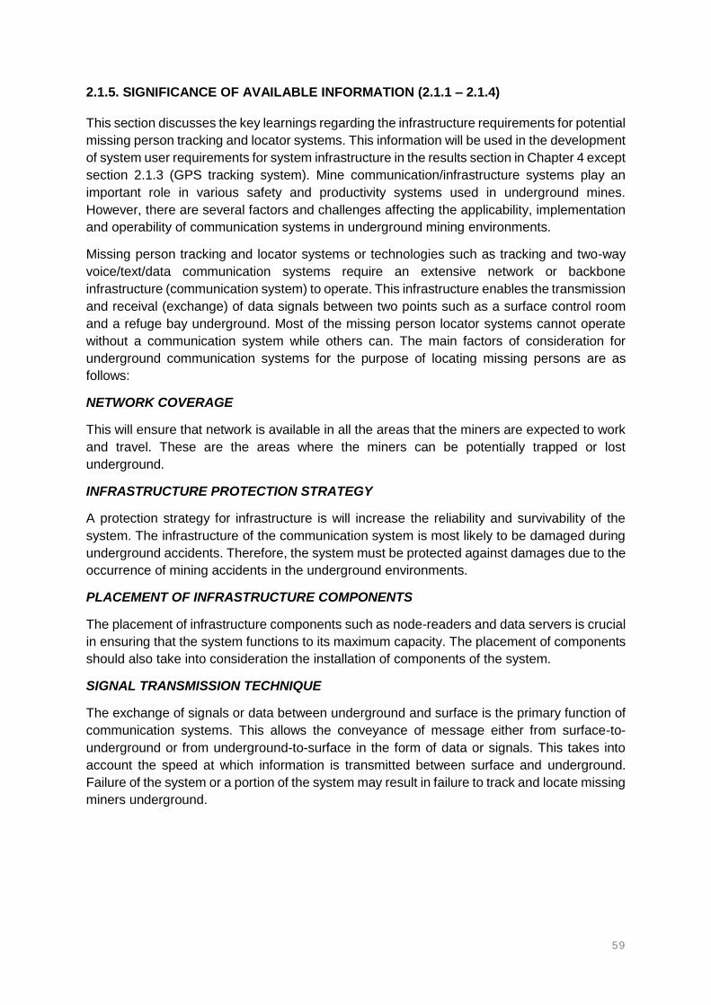
59
2.1.5. SIGNIFICANCE OF AVAILABLE INFORMATION (2.1.1 – 2.1.4)
This section discusses the key learnings regarding the infrastructure requirements for potential
missing person tracking and locator systems. This information will be used in the development
of system user requirements for system infrastructure in the results section in Chapter 4 except
section 2.1.3 (GPS tracking system). Mine communication/infrastructure systems play an
important role in various safety and productivity systems used in underground mines.
However, there are several factors and challenges affecting the applicability, implementation
and operability of communication systems in underground mining environments.
Missing person tracking and locator systems or technologies such as tracking and two-way
voice/text/data communication systems require an extensive network or backbone
infrastructure (communication system) to operate. This infrastructure enables the transmission
and receival (exchange) of data signals between two points such as a surface control room
and a refuge bay underground. Most of the missing person locator systems cannot operate
without a communication system while others can. The main factors of consideration for
underground communication systems for the purpose of locating missing persons are as
follows:
NETWORK COVERAGE
This will ensure that network is available in all the areas that the miners are expected to work
and travel. These are the areas where the miners can be potentially trapped or lost
underground.
INFRASTRUCTURE PROTECTION STRATEGY
A protection strategy for infrastructure is will increase the reliability and survivability of the
system. The infrastructure of the communication system is most likely to be damaged during
underground accidents. Therefore, the system must be protected against damages due to the
occurrence of mining accidents in the underground environments.
PLACEMENT OF INFRASTRUCTURE COMPONENTS
The placement of infrastructure components such as node-readers and data servers is crucial
in ensuring that the system functions to its maximum capacity. The placement of components
should also take into consideration the installation of components of the system.
SIGNAL TRANSMISSION TECHNIQUE
The exchange of signals or data between underground and surface is the primary function of
communication systems. This allows the conveyance of message either from surface-to-
underground or from underground-to-surface in the form of data or signals. This takes into
account the speed at which information is transmitted between surface and underground.
Failure of the system or a portion of the system may result in failure to track and locate missing
miners underground.
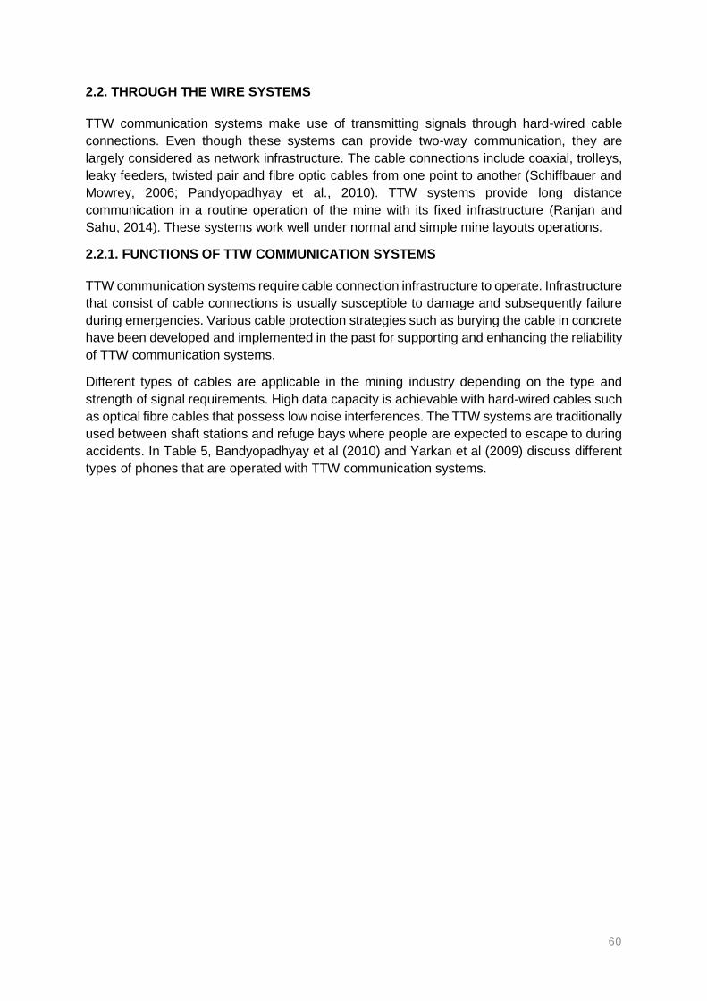
60
2.2. THROUGH THE WIRE SYSTEMS
TTW communication systems make use of transmitting signals through hard-wired cable
connections. Even though these systems can provide two-way communication, they are
largely considered as network infrastructure. The cable connections include coaxial, trolleys,
leaky feeders, twisted pair and fibre optic cables from one point to another (Schiffbauer and
Mowrey, 2006; Pandyopadhyay et al., 2010). TTW systems provide long distance
communication in a routine operation of the mine with its fixed infrastructure (Ranjan and
Sahu, 2014). These systems work well under normal and simple mine layouts operations.
2.2.1. FUNCTIONS OF TTW COMMUNICATION SYSTEMS
TTW communication systems require cable connection infrastructure to operate. Infrastructure
that consist of cable connections is usually susceptible to damage and subsequently failure
during emergencies. Various cable protection strategies such as burying the cable in concrete
have been developed and implemented in the past for supporting and enhancing the reliability
of TTW communication systems.
Different types of cables are applicable in the mining industry depending on the type and
strength of signal requirements. High data capacity is achievable with hard-wired cables such
as optical fibre cables that possess low noise interferences. The TTW systems are traditionally
used between shaft stations and refuge bays where people are expected to escape to during
accidents. In Table 5, Bandyopadhyay et al (2010) and Yarkan et al (2009) discuss different
types of phones that are operated with TTW communication systems.

61
Table 5: Types of underground mining phones as part of the TTW communication systems (Bandyopadhyay et al., 2010; Yarkan et al., 2009)
Type of
phone
Description of phone
Magneto-type
phones
These phones usually consist of a battery, hand generator, bells, hook
switches, line coupler, transmitter and receiver. The magneto phones the
lack signal strength when used for multiple phones.
Sound-
Powered
phones
These phones enable voice communication from the voice of the speaker
without requiring external energy. These phones benefit high efficiencies
from converting voices of the transmitter and receiver into electrical
energy. The receiver and transmitter are usually connected by a single-
line wire. Good quality voice communication can be achieved over short
distances and under quiet conditions.
Bell signaling
phones
These are commonly used phones in shaft systems between a cage
operator and a person requesting a cage at a certain level. The phones
operate by pulling a pull-bottle that causes an associated switch to close.
When the pull-bottle is pulled, voltage is applied to a buzzer at that level,
buzzer at hoist room and other buzzers in the shaft.
Pager phones These are also amongst the commonly used type of phones for
communication in underground mines. The phones operate on a two-wire
cable, which can only enable one conversation at one time. The phones
usually consist of a self-contained battery, speaker and switch circuit.
These phones operate on the press-to-talk mode. This prevents
simultaneous conversations within the same line-wire system.
Dial and pager
phones
These phones are highly restricted by their potential hazard in methane
prone environments due to their high voltage power requirements. The
phones lack the ability to locate a person who is not in range to the phone
station.
TTW communication systems such as magneto phones, paging phones and sound powered
phones have been widely used in conventional underground mines. However, these hard-
wired communication systems can only provide limited voice communication, with no
electronic tracking capabilities (Reddy et al., 2011). Whilst no tracking is provided by the wired
systems, TTW two-way voice communication systems can be used to locate people by
phoning stations, talking or exchanging instructions over the phone between surface, shaft
station and the refuge chambers.
The factors restricting TTW systems include the fact that the radio frequency signals fed into
the underground cables can only be distributed along the length of the cable (Bandyopadhyay
et al., 2010). One of the biggest disadvantages of TTW systems is the lack of redundancy
(Bandyopadhyay et al., 2010). Redundancy can be described as factor of increasing the
survivability of a system against damage by duplicating its function.

62
TTW systems lack the ability to maintain communication with surface after an accident has
occurred and the cables are damaged. This is mainly due to the fact that the system has a
single pathway between surface and underground. Wired systems are unlikely to withstand
mining accidents (Maity, 2015). However, redundancy provides the opportunity to enable a
single system to have two or more pathways of communication between surface and
underground or alternatively installing two or more systems with different pathways. In this
way, communication can be maintained even when one pathway is disrupted.
2.2.2. ETHERNET AND FIBRE OPTICS
Ethernet is described as the technology of connecting computer devices to each other and to
the internet in a local area networks (LAN) system using Ethernet cables. Ethernet is the most
extensively used and installed LAN technology in various industries and applications. As
Ethernet operates according to the IEEE 802.3 standards, it uses coaxial, fibre optic and
unshielded twisted pair (UTP) cables (Bandyopadhyay et al., 2010). These cables are
commonly known for their capability to transmit data at high rates (capacity).
Ethernet connectivity requires a physical communications link between two devices that are
connected some distance apart (NIOSH, 2013). Ethernet operates on the IEEE 802.3
communication standard that creates and is used on LAN. Ethernet can be used to form the
LAN for mines, either wirelessly or through cables. The communication link is between a
transmitter (device emitting or transmitting signals) and a receiver (device receiving radio wave
signals). Information carried over radio wave signals is transferred from the sender to the
receiver along Ethernet cables as the medium of transmission.
LAN allows several computers to connect with one another. The computers form an Ethernet
LAN. The LAN allows the computers to exchange and share information with each other over
the Ethernet cable connections. Ethernet cables are internet connection cables precisely used
for LAN. Each computer starts by checking and verifying that the network line is clear before
sending information over the LAN. If one computer is already sending or transmitting
information, the next computer waits for the line to be clear before it can transmit its
information. This is done to ensure that there is no collision of signals over the cable. A collision
of signals would affect the accuracy of data being transmitted. Signals traffic in the cables may
also affects the speed of transmission (NIOSH, 2013).
Multiple computers in various locations can be connected to each other through Ethernet
cables and can easily exchange information with each other. Data from the mine can be
transferred through Ethernet cables between surface (control room) and underground.
However, one of the drawbacks of Ethernet cables is the required wire connections that can
be limited by the length of the cable (NIOSH, 2013).
The use of hard wired connections limits the installation of Ethernet in various parts of the
mine. A typical Ethernet infrastructure is comprised of network servers and data transmission
cables that enable internet connectivity. Various sub-systems can be connected or integrated
into the Ethernet network backbone. The MOXA Ethernet network backbone (MOXA Group,
2017) is an example of the integration of sub-systems such as personnel positioning, wireless
communication, control and monitoring. The sub-systems are connected to a single Ethernet
backbone with capabilities of transmitting data, voice and video transmission in real-time as
can be seen in Figure 12. The network infrastructure is installed from surface and extended
underground through the shaft.

63
Figure 12: Functions, capabilities and the applicability of Ethernet in typical underground mining environments (MOXA Group, 2017)

64
Ethernet network connections involve an extensive cabling work in the area that requires
network coverage. Figure 12 also illustrates the complexity of extending and installing network
infrastructure in the various working areas of a typical underground mine. Various types of
cables exist for potential application in underground mines, and this includes copper wires,
fibre optic, coaxial and unshielded twisted pair (UTP) cables.
DESCRIPTION OF FIBRE OPTIC CABLES
Fibre optic cables use light pulses for the transmission of information through fibre-wired lines,
rather than using electronic pulses for transmitting information as with the traditional copper
lines. Fibre optic cable connections are used to create backbone infrastructures. These cables
have higher transmission rate capabilities (Forooshani et al., 2013). The cables also have the
capability to enable wireless connectivity in underground mines. The cables possess
numerous advantages as compared to copper cables, such as its low attenuation properties.
Its low attenuation characteristics allow the cable to transmit signals over longer distances
without noise interferences.
The fibre optic cables may work together with or alternatively require a data-translating device
in order to establish communication between two or more devices. The translator, or
translating device, receives coded electronic pulse data from the fibre optic cables. The
translator is responsible for processing and translating the data into equally coded light pulses.
This is in the form of data that can be transmitted from one device to another through the air
as a transmission medium.
DESCRIPTION OF UTP CABLES
The UTP cables are made of two insulated copper cable wires that are twisted around each
other throughout the length of the cable. A UTP cable connection system is one of the least
expensive transmission medium over commercially available cables in the market (NIOSH,
2013). These cables are commonly used for standard pager telephones to provide
communication between surface and underground.
DESCRIPTION OF COAXIAL CABLES
Coaxial cables are often used in conjunction with the fibre optic and twisted pair cables.
However, the coaxial cables have lower signal losses and good shielding characteristics when
compared to the other cables. These cables may also be more expensive compared to twisted
pair cables (NIOSH, 2013).
2.2.3. LEAKY FEEDER SYSTEMS
Leaky feeder systems make use of cables that are designed to transmit and receive radio
signals through small holes or slots that exist over the length of a cable (Wand and Mei, 2001).
The leaky feeder cable comprises of coaxial cables that permit signals to leak out (emit) or
feed into the cable (receive). The configurations of the cable connection can be either of a
twin-core or of a coaxial cable, being analogous to a surface antenna. The leak in-and-out of
signals allows the transmission of radio waves to radiate over the length of the cable
(Schiffbauer and Mowrey, 2006; Forooshani et al., 2013; Raveon Company, 2017; Douglas,
2014; NIOSH, 2013). These cables are one of the most commonly installed in underground
operations for the distribution of voice and data signals (Bandyopadhyay et al., 2010).

65
Farahneh and Fernando (2014) emphasise that leaky feeder systems are the most extensively
used medium of transmitting data signals in underground mining environments and tunnels.
The cables consist of special, coaxial cables that are made of core and partially shielded slots
such that the signals can radiate or fall out of the cable (Douglas, 2014; Schafrik et al., 2013).
The cable allows radio signals to “leak out” from the cable into the mine environment as radio
waves (Douglas, 2014; Schafrik et al., 2013; Forooshani et al., 2013).
The cable allows an inflow of signals into the leaky feeder system as illustrated in Figure 13.
The signals are then transported to a surface central unit as data or information (Novak et al.,
2009). The signals travelling along the cable may be lost due to radiation. This necessitates
the need for amplifiers at regular intervals to maintain signal strength (Schafrik et al, 2013).
The leaky feeder cable acts as an antenna to provide clear communication as signals radiate
in and out of the cable.
Figure 13: Signal radiation in leaky feeder system (Raveon Company, 2017)
According to Forooshani et al (2013), leaky feeder systems have an increased signal
transmission range. This is because the degree of attenuation over the length of the cable is
lower than that of the free-space propagation in a typical mine environment. These cables
become extremely crucial in areas where direct line of contact with standard antennas is
difficult to achieve. The cables, as an analogous antenna, with the signal radiating and
receiving slots that are cut into the outer shielding to allow the signals to radiate in and out
over the length of the cable. This allows the cable to create a good network coverage range
in areas that are difficult to reach.
The purpose of the outer shielding of the cables is to contain signals inside the cable as much
as possible and at the same time preventing interferences from external cables
(Bandyopadhyay et al., 2010). The outer shielding is aimed at reducing attenuation. The
weakening of signal strength in the cable necessitates the use of amplifiers (Forooshani et al.,
2013) at certain intervals, approximately 300 to 350m apart according to Raveon Company
(2017). Figure 14 shows the main components of the leaky feeder cable (Wall to Wall
Communications, 2017).

66
Figure 14: Components of a typical leaky feeder cable system used in shafts and tunnels (Wall to Wall Communications, 2017)
Leaky feeder cables are capable of simultaneously transmitting voice and data in the same
cable line. A good leaky feeder system is characterised by basic two-way voice and data
communication applications. The cables use either of a very high frequency (VHF) or of an
ultra-high frequency (UHF) bands for underground mining applications. The VHF operates at
a frequency of about 150 MHz for data transmission and the UHF operates at about 450 MHz
and is capable of voice data transmission (Elia et al., 2013).
The VHF frequencies experience reduced line attenuation and coupling losses than the UHF
cables (Elia et al., 2013). However, the UHF cables can accommodate larger bandwidths. The
UHF cables can also propagate signals more efficiently than VHF around corners and crosscut
(tunnel openings) excavations in underground mines (NIOSH, 2013). The reach range of UHF
is greater than that of VHF cables. The leaky feeder cables can operate over the 2.5 GHz
frequency band to support Wi-Fi standards (Elia et al., 2013). However, this is not a common
practice in the mining industry.
The leaky feeder cables establish communication between radio transceivers and receivers
(carried by the mine personnel) underground. The cables and the receiving devices are linked
with each other wirelessly and air is used as the medium of signal exchange. The data signals
leaking from the cable are received by nearby end-devices (Fisahn et al., 2005). The cables,
usually attached against the hangingwall, and act as distributed antennas. The cable is then
able to transmit signals to the underground workings (Figure 15) as well as establish
communication with tags wirelessly (Figure 16).

67
Figure 15: Leaky feeder cable connection in underground mines (NIOSH, 2013)
Figure 16: Leaky feeder cable communication with RFID tags (NIOSH, 2013)
Figure 15 and Figure 16 demonstrate the installation and operation of a leaky feeder system
in a typical underground mining environment. The presence of the cables in a particular area
provides network coverage. The quality and quantity of information transmitted over leaky
feeder cables can be affected by attenuation. A reduction in signal strength has a negative
influence on the efficiency and effectiveness of leaky feeder systems. Loss in the strength of
a signal, referred to as attenuation, can occur in any type of signal transmission technique,
whether it is digital or analogous.
According to Elia et al (2015) attenuation in underground mining leaky feeder applications is
caused by the accumulation of dust on the cable, which subsequently affects the performance
of the cables. The accumulation of dust around the perimeter of the cable affects the
performance of leaky feeder cables in terms of attenuation. Elia et al (2015) found that the
refining of amplifier distance intervals as the solution to maintaining sufficient coverage. The
study by Elia et al (2015) showed that an increase in dust thickness around the perimeter of
the cable requires that the distance between the amplifiers be reduced.

68
The distance that separates amplifiers becomes a function of the dust thickness. Therefore,
to reduce the effect of attenuation, the solution found by Elia et al (2013) was to determine the
right distance between amplifiers without suggesting major variations in the existing
infrastructure (Elia et al., 2013).
Consider Figure 17; Miner 1 who is within read range to the leaky feeder cable communicates
with Miner 2 who is also within read range of the leaky feeder. Miner 1 and Miner 2 can
exchange voice and data signals through the leaky feeder system to establish a
communication line. If Miner 1 and Miner 2 are carrying location tags, then their locations can
also be detected from surface in real-time. This is because the leaky feeder system can also
act as a network infrastructure and can relay information between surface and underground.
However, leaky feeder systems are commonly used for two-way voice applications.
In Figure 17, Miner 1 and Miner 2 can report their locations in two-way voice communication
to the control room on surface by talking over handheld radios. Power is usually lost in the
process, as signals leak out of cable. The inner core supplies DC voltage to some in-line
amplifiers to maintain signal strength (Douglas, 2014; Schafrik et al, 2013). Multiple
frequencies are used for transmitting signals, therefore providing many channels for
communication to a single central base server on surface. All the channels are capable of
transmitting signals in and out of the cable.
Figure 17: Two miners communicating with each other over a leaky feeder system at a certain distance apart (NIOSH, 2013)
Leaky feeder cables for underground applications usually operate at 150 to 450 MHz while it
can operate at 900 MHz to 1800 GHz in other industries (Schafrik et al, 2013). Leaky feeder
cables have a read range of approximately 30m in typical underground mining conditions and
up to 90m where line of sight is available. Signal transmission range of leaky feeder cables is
between 40 and 50m (Schafrik et al, 2013), where the transmission range is about 30m and
the receive range is reaches 90m (Schiffbauer and Mowrey, 2006). A typical leaky feeder
amplifier installed underground is shown in Figure 18.

69
Figure 18: Amplifier of a leaky feeder system installed on the hangingwall of a mine haulage (www.meglab.ca/en/products/wireless-communication/, 2017)
2.2.4. SIGNIFICANCE OF AVAILABLE INFORMATION (2.2.1 – 2.2.3)
TTW voice communication systems have been used extensively in underground mining
operations. These systems were initially used for two-way voice communication at fixed points
such as shaft stations and the refuge bays. TTW communication systems have recently been
transformed into creating network infrastructure for underground mining environments. This
included leaky feeder systems and Ethernet infrastructure with application in underground
mining.
The advantages and disadvantages of Ethernet and leaky feeder systems in terms of
underground mining applications are discussed in Table 6. The individual characteristics of
these systems will be used in the results section in Chapter 4 to determine the most suitable
infrastructure system for underground mining environments. The information on the different
types of phones will not be used further, but the study will use TTW two-way voice
communication system in Chapter 4.

70
Table 6: A summary of TTW communication systems (Ethernet and leaky feeder) for underground mining applications
Communication
system
Functionality Advantages Disadvantages
Leaky feeder Radiates signals in and
out of the cable to
provide underground
network for two-way
communication for
locating missing miners.
Leaky feeder systems provide good network
coverage in various parts of the mine where
the cables are present. These cables can be
well installed in areas that are hard to reach.
Therefore, miners can be tracked in confined
spaces of the mine.
Leaky feeder communication systems are limited
by line of sight. Obstacles can prevent the system
from tracking and establishing communication
between the rescue teams and the missing
persons. Objects that affect line of sight should be
investigated and removed to enable adequate
line of sight.
Leaky feeder systems do not require the
installation of readers that are used for
receiving and transmitting radio frequency
signals for tracking miners.
The system and its cables are sensitive to
damage. Therefore, the cables must be protected
from accidents such as explosions, falls of ground
and inrushes.
Multiple voice communication channels are
possible on the same leaky feeder cable. This
will allow adequate communications at the
same time.
Relatively short-range connectivity between cable
and devices. The tags or handheld radios must be
relatively close to the node-readers to enable
communication.
The leaky feeder system is capable of
achieving voice, data and video
communications for effectiveness.
No Ethernet solution via cable modem.
Fibre
Optics/Ethernet
cables
Provides LAN to the
underground mining
environment all the way
from surface to enable
tracking and two-way
communication.
High data transmission capabilities. This
allows the system to track a large amount of
tags at the same time without interferences.
The system is highly susceptible to damage
during accidents. The system must therefore be
protected against accidents that can cause
damages on the cables.
Longer reach range communication between
the readers and tags carried by personnel.
Tags at longer distances can be detected by
the node-readers.
Requires power supply for the cable and readers.
Adequate power supply must be available at all
times for the system to operate adequately.

71
2.3. THROUGH-THE-AIR TRACKING AND COMMUNICATION SYSTEMS
TTA communication systems operate on a low to medium frequency band, wirelessly (without
any cable connections) to enable radio transmission technologies in both coal and metal
underground mines (Bandyopadhyay et al., 2010; Schiffbauer and Mowrey, 2006; Forooshani
et al., 2013; Yarkan et al., 2009). The TTA communication systems make use of radio
frequency identification (RFID) node-readers or access points such as Wi-Fi, ZigBee or
Bluetooth for transmitting signals to the underground mining environment (Bandyopadhyay et
al., 2010; Forooshani et al., 2013; Yarkan et al., 2009; Radinovic and Kim, 2008).
COMPONENTS OF TTA COMMUNICATION SYSTEMS
A typical wireless, RFID communication system consist of tags (carried by mine personnel),
node-readers (installed on the tunnels), antennas (connect tags and readers), a server
computer and backbone network infrastructure (see Figure 19). These components of the
system are installed underground throughout. Lee et al (2007) conducted a comparative study
of the wireless connectivity protocols. Four wireless protocols were investigated and includes
Bluetooth, ultra-wide band (UWB), ZigBee and Wi-Fi. The node-readers require strategic
placement, usually on the hangingwall, to provide adequate coverage in a wide area where
personnel are expected to work and travel. The various types of TTA communication systems
are capable of providing two-way voice, video and data transmission (Bandyopadhyay et al.,
2010). TTA communication technologies differ by their frequency bands in which they operate
(Radinovic and Kim, 2008).
Devices of TTA wireless systems comprise of an antenna for signal transmission, a signal
transmission medium and a signal-receiving antenna. This type of communication system is
heavily dependent on the network coverage or reach range, which can be substantiated by
the maximum distance between the transmitting and receiving devices to maintain adequate
communication during signal exchange. Signal propagation can be extended through a
distributed antenna system. However, the extension of a TTA wireless system can be heavily
affected by environmental atmospheric (e.g. dust, moisture content in the air and air velocity)
and external factors (presence of equipment, type of rock, sizes of tunnels and curving and
straight tunnels) in underground mines (Zhang et al., 2001).
APPLICATIONS OF TTA COMMUNICATION SYSTEMS
According to Forooshani et al (2013), TTA communication systems are applicable in a wide
range of services such as two-way voice communication, personnel and equipment tracking,
data communication, atmospheric sensing and remote-control features. Radinovic and Kim
(2008) investigated the applicability and feasibility of RFID, Wi-Fi and Bluetooth wireless
technologies for tracking mine personnel in underground mining operations. Radinovic and
Kim (2008) evaluates the applicability and limitations of real-time location systems.
The study then suggests that RFID is better suited for relatively small areas, while Wi-Fi has
been seen as a promising technology due to its broad variety of positioning devices that
already exist in the market. However, Wi-Fi tags are usually costly when compared to RFID
tags. Wi-Fi tags costs about USD 100 per unit while RFID tags cost between USD 65 to 75
per unit (Radinovic and Kim, 2008). According to Forooshani et al (2013), wireless LAN mesh
network systems that are redundant, self-learning and self-healing provide adequate reliability
for wireless communication systems.

72
Figure 19: Through the air radio frequency based tracking and communication system with its backbone infrastructure (Forooshani et al., 2013)

73
Figure 19 also illustrates a typical TTA communication system with its backbone infrastructure
as employed in an underground mine. Wireless communication technologies offer relatively
short range, low-power positioning capabilities in general (Forooshani et al., 2013). The
capabilities and performance of communication and tracking systems are very important
factors to be considered when selecting a system.
Over-engineering the system might be needlessly expensive and at the same time under-
engineering the system affects and reduces the reliability of the system (Forooshani et al.,
2013). TTA communication systems require a wireless link, with the air used as the medium
for signal transmission. These systems are free from damage due to explosions and fall of
ground accidents. The performances of any communication system are characterised by
signal propagation. Attenuation in underground mines increases due to the roughness and
unevenness of the walls (Ranjan and Sahu, 2014).
2.3.1. RFID
RFID is a wireless method of storing and retrieving data signals through the transmission of
radio waves. This method is widely used in industries such as mining, airports and facilities
(Radinovic and Kim, 2008; Mahmad et al., 2016). NIOSH (2013) conducted extensive
research on RFID communications and tracking systems for underground mining applications.
The RFID technique is one specific topic widely studied for the purpose of tracking missing
persons in underground mining environments. This is provided through real-time data
collection (Mahmad et al., 2016).
Radio frequency systems provide information storage technology in the form of coded signals
through microchips. The information is read and stored remotely with no physical contact, but
only using energy in the radio frequency spectrum. RFID is the technology of electromagnetic
and radio waves for the detection of numbers that identifies objects uniquely (Radinovic and
Kim, 2008). The unique numbers are stored on an integrated circuit that is connected to an
antenna. This can be used for various applications in mining (Mahmad et al., 2016).
Chiu et al (2011) defines radio frequency as an automatic identification mechanism via radio
waves as commonly used and developed for the retailing and logistics sectors. The retail and
logistics sectors have been using RFID technology for stock management, theft prevention,
and safe and secure supply chain for better inventory control. The integrated circuit and
antenna of the RFID system combines some form a device called a transponder, generally
referred to as a tag. The second device required in RFID systems is the reader, which
communicates with the tag to identify the numbers stored in the tag. The reader then transmits
the numbers detected from the tag into an information system form that interprets, processes
and stores the data.
RFID is classified into passive, semi-passive and active tags (Mishra et al., 2014; Chiu et al.,
2011). Active tags require an external power source, whereas passive tags draw energy from
the readers. Semi-passive RFID tags consist of a chip circuit that runs on a battery, while the
device communicates by drawing power from the reader (Chiu et al., 2011). The readers emit
radio frequency signals via the antennas, the signals are received by other antennas on the
tags. The RFID system is greatly dependent on inductive and capacitive coupling.

74
RFID systems make use of node readers and tags that communicate with each other to
provide the locations of mine personnel. The readers are strategically installed at known
locations as reference points, and the mine workers wear or carry the tags at all times when
they enter the mine. The tags can either passive or active, and are uniquely assigned to each
mine worker with a unique identification feature. The miners wear the unique tags that
communicate locations or their presence to the read range of the node-readers installed
around the mine. The tags worn by the miners are detected when entering a radio frequency
(RF) range of the node readers, hence detecting the location of the miner wearing that tag.
The tag-and-reader communication information is relayed to a central point (server) on surface
through data cables and/or wireless mesh networks as illustrated in Figure 20. The surface
central point (control room) will immediately know that the miner is within a certain radius. In
the RFID system, the location of the miner is a function of the RF range or detection radius of
the node readers. The control room will only know of the radius in which the miner is being
detected within. When the miners move across at least two readers, the direction in which the
miner is travelling can be determined and hence giving a more precise location.
Figure 20: Communication between RFID tags and readers through the air as transmission medium (Bouet and Dos Santos, 2008)
The RFID system cannot determine the locations of the miners if the tags are not within the
detection range of any reader. The readers require strategic placements to avoid creating blind
spots and overlapping as illustrated in Figure 21 and Figure 22. This is required to ensure that
full coverage detection is achieved underground. Full coverage is characterised by shaft-to-
face detection and is achieved through effective and strategic installation of the readers. The
reader-and-tag detection works on line-of-sight, even if the tags are within range. The
effectiveness of the RFID system is a function of the reference positions or placement of the
node readers and the number of readers required. This can give the location and direction in
which the miner was moving (NIOSH, 2013).
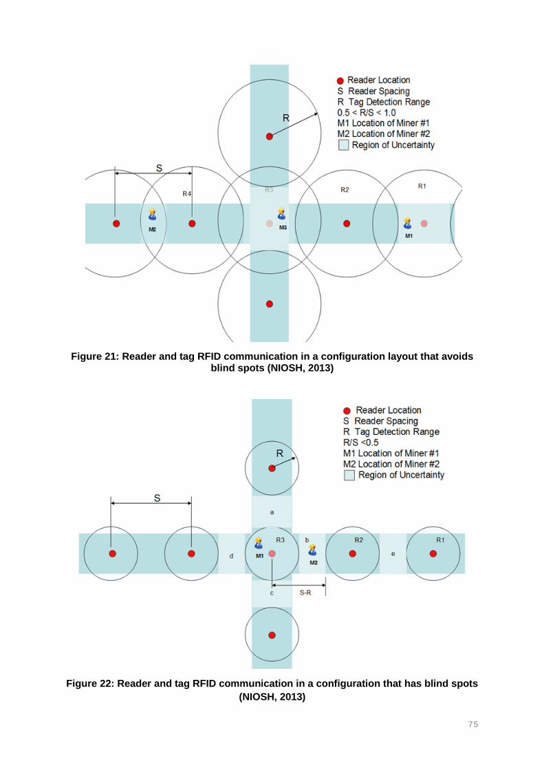
75
Figure 21: Reader and tag RFID communication in a configuration layout that avoids blind spots (NIOSH, 2013)
Figure 22: Reader and tag RFID communication in a configuration that has blind spots
(NIOSH, 2013)

76
The distance between two node-readers and tags is an important factor in RFID systems as
signals becomes weaker with an increase in distance between two node-readers. The RFID
technology can be used to track mining personnel under hostile environments (Mishra et al.,
2014). This requires strategic placement of the node-readers to ensure maximum coverage in
the workings.
RFID technologies can also enhance the management and control of production fleet, and the
control of hazardous materials such as tracking explosives and detonators (Mishra et al., 2014;
Mahmad et al., 2016). All these applications depend on the installation of node-readers.
According to Mishra et al (2014) RFID tagging and tracking systems present a new opportunity
for mines to become pervasive computing environments.
The RFID technology is widely determined and defined by frequency ranges and
characteristics of the technology. The efficiency of communication between the tag and the
node-reader is a function of the read range of the readers. The readers have a limited radius
range. Tags that enter into read range can be detected by the reader. The interval spacing
between adjacent readers is a crucial factor in terms of areal tracking coverage. When the
readers are too far apart, a blind spot occurs (Figure 27). Tags within the blind spots cannot
be detected by any readers. When the readers are too close to each other, an overlap in the
tracking coverage area occurs (Figure 27). The overlap area may cause confusion between
the two readers.
Mishra et al (2014) continues to explain that the frequency ranges, characteristics and
properties of RFID technologies. The frequency of the node-readers determines the distance
between two node-readers, as shown in Figure 26 and Figure 27. The low frequency RFID
involves passive tagging with short-range distance for tracking. Active RFID systems require
antennas and can achieve relatively long-range distances. UHF tend to be imperfect in
underground mining environments with some tags having a possibility of not being detected
(Mishra et al., 2014). Semi-passive RFID tags show some potential for applications in
underground mines, especially with regards to tracking personnel, mobile equipment and
assets.
Active RFID technologies have numerous advantages due to their longer read range
compared to passive RFID. Signal transmission between a reader and tag can be affected by
the presence of metallic objects that can reflect the radio frequency (RF) signals and hence
causing confusions between the readers and tags. RFID systems can also be affected by
superimposed signals; this refers to multiple tags communicating with the same reader.
The RFID system has a limited number of tags that can be detected by the same reader at a
certain time. The RFID system is electronic or automated in nature; the readers automatically
detect the tags as soon they enter into the RF range. This makes the system very easy to use
and operate by the mine personnel and control room operators. The RFID systems make use
of normal electricity from current mine infrastructure and may have back up battery supply in
case of emergency.
The communication and tracking data from the tags and node readers is transmitted to surface
for processing. Data transmission is possible using wired fibre optic and leaky feeder data
cables, or any other wireless link dedicated for the readers. The transmission of data from the
readers to the control room should be effective and reliable to ensure accurate results. The
underground data reports to surface stations in real-time.

77
The node-readers and data transmission cables may be easily damaged by accidents. This
will lead to a loss of data if the readers and cables are damaged. Wireless RFID systems use
air as a signal transmission medium before the data received from the readers is transmitted
to surface servers. In the case of cable damage, the system will show the last known locations
of the mine personnel. The last known location will remain stored on display. The classification
of passive, semi-passive and active RFID tags is discussed in the next sections.
PASSIVE TAGS RFID
A typical passive RFID tags does not require any form of internal power source. These tags
are powered by electromagnetic energy that is drawn from the RFID reader. The tags operate
without the need for batteries and are only powered by the readers when they are within
proximity. The passive tags rely on radio energy generated by the antennas while the readers
required external power supply in order to transmit signals to the tags. Passive tags only
consist of antennas and an integrated circuit forming the RFID system.
Passive tags wait for signals from the readers in order to respond. The passive tags use a
backscattering process to reflect radio waves back to the readers. In passive tags, energy is
transferred from the readers to the antennas of the tags. The antennas convert the energy
into radio frequency waves. The antennas in the tags draw energy from the radio frequency
waves, which moves to the integrated circuit.
The energy, through the radio waves, powers a chip that generates a signal back to the RF
system. The transfer of signals back from the tag cause a change in electromagnetic or radio
frequency waves which is detected and interpreted by the reader. The frequency range
influences the read range of the tags. The read range of passive tags depends on the size of
the tags, frequency range and effective isotropic radiated power of the antennas (Mishra et
al., 2014).
ACTIVE TAGS RFID
Active RFID tags require an internal power source such as batteries to operate. Active RFID
tags continuously broadcast or radiate their own signals and hence require a continuous power
supply. The read range of active tags can be up to 100m in open spaces, but can be increased
in underground as tunnels form a wave-guide. The wave-guide increases the read range due
to efficient transfer of electromagnetic power from one point to another (Mishra et al., 2014).
The active tags work as beacons that transmit signals to accurately and in real-time, track the
positions or locations of objects, people or mobile equipment.
The active RFID tags consist of a reader, an antenna and the tag. Active tags need to possess
their own source of power in order to enable long-range read and memory banks. The tags
are classified into transponders and beacons. RFID readers send signals first, and then the
transponder tags send signals back in response to the reader. The transponders become
inactive when they are out of range of the reader. On the other hand, the beacon tags do not
wait to receive signals from the readers. The beacon tags automatically emit signals every 3
to 5 seconds. The signals can reach long ranges at low transmission power (Mishra et al.,
2014).
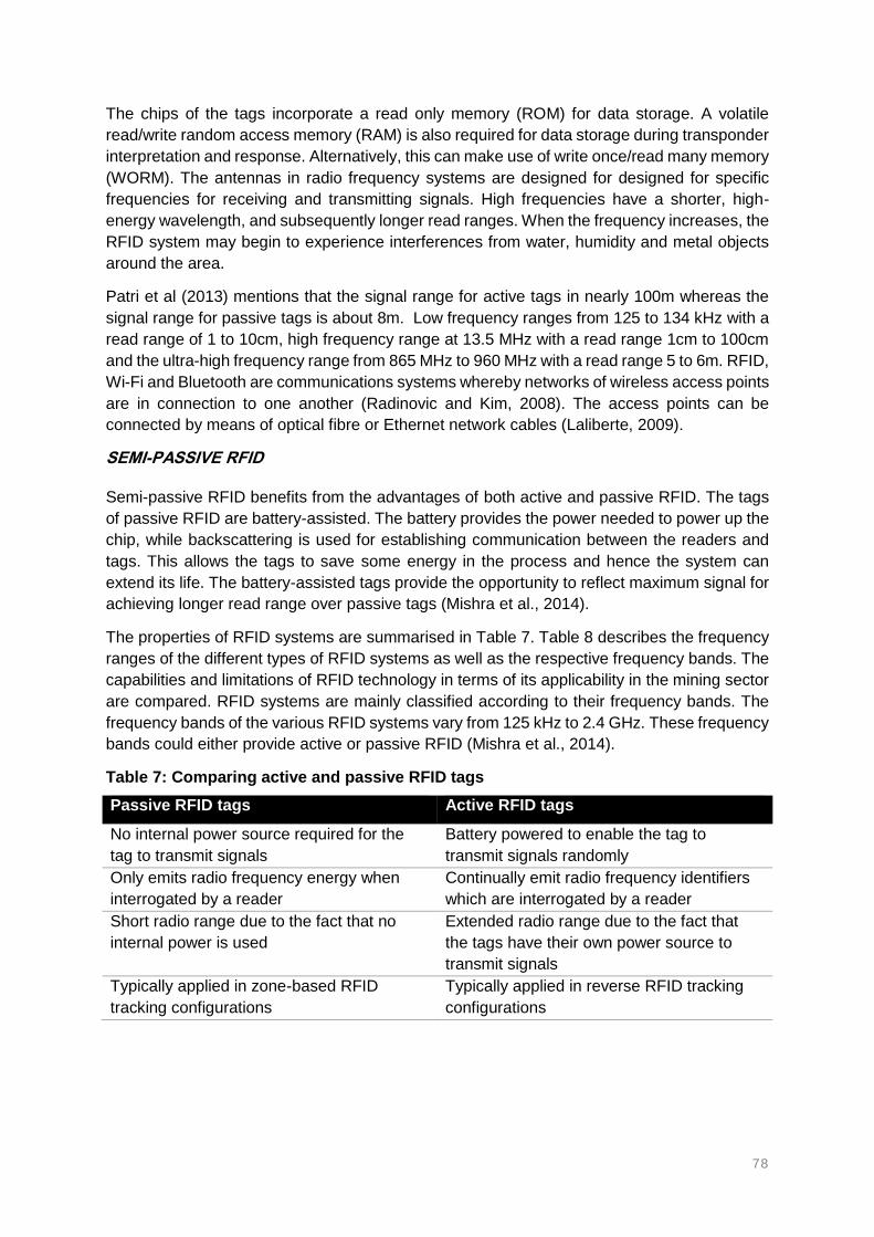
78
The chips of the tags incorporate a read only memory (ROM) for data storage. A volatile
read/write random access memory (RAM) is also required for data storage during transponder
interpretation and response. Alternatively, this can make use of write once/read many memory
(WORM). The antennas in radio frequency systems are designed for designed for specific
frequencies for receiving and transmitting signals. High frequencies have a shorter, high-
energy wavelength, and subsequently longer read ranges. When the frequency increases, the
RFID system may begin to experience interferences from water, humidity and metal objects
around the area.
Patri et al (2013) mentions that the signal range for active tags in nearly 100m whereas the
signal range for passive tags is about 8m. Low frequency ranges from 125 to 134 kHz with a
read range of 1 to 10cm, high frequency range at 13.5 MHz with a read range 1cm to 100cm
and the ultra-high frequency range from 865 MHz to 960 MHz with a read range 5 to 6m. RFID,
Wi-Fi and Bluetooth are communications systems whereby networks of wireless access points
are in connection to one another (Radinovic and Kim, 2008). The access points can be
connected by means of optical fibre or Ethernet network cables (Laliberte, 2009).
SEMI-PASSIVE RFID
Semi-passive RFID benefits from the advantages of both active and passive RFID. The tags
of passive RFID are battery-assisted. The battery provides the power needed to power up the
chip, while backscattering is used for establishing communication between the readers and
tags. This allows the tags to save some energy in the process and hence the system can
extend its life. The battery-assisted tags provide the opportunity to reflect maximum signal for
achieving longer read range over passive tags (Mishra et al., 2014).
The properties of RFID systems are summarised in Table 7. Table 8 describes the frequency
ranges of the different types of RFID systems as well as the respective frequency bands. The
capabilities and limitations of RFID technology in terms of its applicability in the mining sector
are compared. RFID systems are mainly classified according to their frequency bands. The
frequency bands of the various RFID systems vary from 125 kHz to 2.4 GHz. These frequency
bands could either provide active or passive RFID (Mishra et al., 2014).
Table 7: Comparing active and passive RFID tags
Passive RFID tags Active RFID tags
No internal power source required for the
tag to transmit signals
Battery powered to enable the tag to
transmit signals randomly
Only emits radio frequency energy when
interrogated by a reader
Continually emit radio frequency identifiers
which are interrogated by a reader
Short radio range due to the fact that no
internal power is used
Extended radio range due to the fact that
the tags have their own power source to
transmit signals
Typically applied in zone-based RFID
tracking configurations
Typically applied in reverse RFID tracking
configurations

79
Table 8: Summary of frequency bands for the different types of RFID (passive or active) tracking and communication systems (Mishra et al., 2014)
Frequency range
Frequency band
Types of RFID Capabilities and application in mining Limitation for application in mining
Low frequency (LF)
125 – 134 kHz
Passive tags Propagate very well through solid overburden rock and soil
Short range reach distance
Good properties near water and metallic objects
Tags size tends to be larger
131 kHz Active LF RuBee (IEEE standards 1902.1)
Capable of detecting objects in coal slurry and floods
Requires relatively large read antennas
Capable of detecting misfired explosives The use of active tags makes the system expensive
High frequency (HF)
13.56 MHz Used in smartcards and near-field communications with passive RFID tags
Widely used for access control The technology is of very short reach range
Ultra-high frequency (UHF)
433 MHz Active RFID Provides long range communication The maturity of the technology has not been realized in the mining industry
Enables the detection of tags carried by personnel and/or assets
Extensive research is still required to allow implementation
Allows atmospheric environmental conditions
900 MHz Passive and semi-passive RFID
Enables the tracking and tracing of assets and personnel
Relatively small read range compared to active tags
Imperfect accuracies with reading
Microwaves 2.4 GHz Active tags Real-time tracking of locations of personnel and assets
Cannot penetrate through rock and soil
Applied in proximity detection and collision avoidance
Atmospheric environment conditions monitoring

80
2.3.2. RECEIVED SIGNAL STRENGTH INDICATION
Received Signal Strength Indication (RSSI) is a simple, but less accurate wireless sensor
network (WSN) system based on a received signal strength measurement (Wojtas and
Wiszniowski, 2012; Pu et al., 2011; NIOSH, 2013). The RSSI technique is often compared to
the time difference of arrival (TDOA) concept, which has an improved performance. The RSSI
technology has a wide range of applications in underground mines, particularly on personnel
tracking. Node-readers and tags are used in the RSSI systems. The node-readers are
distributed at pre-determined strategic positions in the underground mine workings to detect
mobile tags carried by mine personnel. This provides pre-incident personnel deployment
locations based on proximity, triangulation and trilateration (Pu et al., 2011).
The RSSI tracking information can be used during search-and-rescue operations when mine
personnel are missing underground, especially during the first stage of the rescue operation
when their locations are urgently needed. The RSSI system works well in open spaces, but
has several limitations due to multipath effects in confined spaces. The RSSI technique was
investigated and found to be unsuitable for distance estimation in typical underground mining
tunnels or galleries as demonstrated in Figure 23 (NIOSH, 2013; Dong and Yang, 2015).
The performance of the RSSI system can be negatively affected by errors in distance
measurements of the strength of the received signal-based ranging. Zonal location in RSSI
technique is used to determine the distance of a mobile tag from a coordinator or router as
can be seen in Figure 23. ZigBee and Wi-Fi transceivers estimate the distance between
adjacent nodes based on the RSSI distance. The accuracy of RSSI techniques in indoor
environments is still a challenge. The RSSI systems are often affected by the environments of
indoor conditions. Underground barriers and randomly walking people are amongst some of
the factors affecting the accuracy of the RSSI technique.
Figure 23: The concept of received signal strength indication between two tags (NIOSH, 2013)

81
2.3.3. WI-FI CONNECTIVITY FOR UNDERGROUND MINING
Wi-Fi, short for Wireless Fidelity, is an information transmission, wireless connectivity, radio
waves technology that possesses two-way voice, text and data communication capabilities.
Wi-Fi technology is simply described as the ability to connect to the internet (LAN) wirelessly.
Laliberte (2009) defines Wi-Fi as an open architecture of a network of wirelessly connected
access points through optical fibre or Ethernet cables. Wi-Fi allows multiple devices to connect
to the same router wirelessly or through the air. Wi-Fi can cover a wide area with high
communication speed, and provides adequate communication (Moridi et al., 2014). However,
this will require high power consumption, which is often provided through cabling for
continuous supply and access points connections (Moridi et al., 2014).
Wi-Fi is capable of transmitting voice, texts and videos through its high data rate capacities
(Laliberte, 2009). Wi-Fi technology is quickly evolving in indoor and underground mines and
can be well used for tracking of equipment and mineworkers (Pathak et al., 2014). Wireless
tags and readers can be easily used in conjunction with Wi-Fi connection for tracking missing
people in underground environments. Wi-Fi is operated, managed and continuously improved
by the global Wi-Fi Alliance (Wi-Fi Alliance, 2017). The Wi-Fi Alliance defines the standards
of Wi-Fi and is comprised of a worldwide network of companies.
Wi-Fi technology works between a receiving device and a transmitting device (access points
or readers). The wireless access points convert either information into radio waves or radio
waves into information, depending on the direction of communication. Information transferred
from surface to underground in the form of data is converted into signals to create a local area
network. The signal strength of the radio waves determines the reach range and area of
connectivity (network coverage). The strength of the signals decreases further away from the
position of the access point. The communication process, from access point to local area
network is reversible. The reversible process works where an active tag emits signals that are
received by the reader. The active tags require an external power source to be able to send
signals backwards to the router (Radinovic and Kim, 2008).
Unlike Ethernet, Wi-Fi allows wireless connectivity between the receiver and transmitter.
However, Ethernet provides faster speed, lower latency and experience less interferences.
Wi-Fi defines the equivalent of Ethernet, but for wireless local area network. In underground
mining applications, access points connect to each other through Ethernet or optical fibre
cables to expand network connectivity (Laliberte, 2009). It is now possible to connect access
points wirelessly, without Ethernet cables. However, the speed of transmission becomes very
low. The technique of connecting access points wirelessly is referred to as a mesh network.
Wi-Fi operates on the 2.4 GHz (IEEE 802.11a, b and g standard) direct sequence spread
spectrum in which a maximum transmission rate of 54 bits per second can be reached
(Radinovic and Kim, 2008; Zhang et al., 2009; Laliberte, 2009). The transmission rate of Wi-
Fi signals can be greatly influenced by the relatively higher strength of the signals. Wi-Fi
technology uses a coding technique referred to as the orthogonal frequency division
multiplexing (OFDM) as explained by Bandyopadhyay et al (2010). The OFDM is an efficiency
coding technique that splits the radio signals into several sub-signals prior reaching the
receivers as the end user. The transmission rate can be adjusted to 5.5, 2 or 1 bit per second
(bps) in accordance to the strength of the signals (Zhang et al., 2009).

82
A typical Wi-Fi network system will comprise of access point nodes, network servers and the
wireless site of connectivity. As the transmission speed of Wi-Fi reaches up to 54 Megabytes
per second (Mbps), this means a long reach range can be achieved (Zhang et al., 2009). Wi-
Fi 802.11-standard is compatible with many devices that exist today. Wi-Fi, as a mine
personnel location tracking system, consist of readers, access points, electronic tags worn by
the mine personnel, serial interfaces as well as connecting cables (Zhang et al., 2009). The
access points are installed around the mine complex where people are expected to work and
travel.
The accuracy of tracking information is dependent on the number of installed access point
nodes. The access point nodes are installed at certain intervals according to the read range,
which can be up to 200m depending on the type of environment, and the installation intervals
are reduced to about 50m at the working face (Zhang et al., 2009). The strategic placement
of the access points creates an automatic communications network, which is the location
network. The main function of the network nodes is to read signal strength from the mobile
tags attached to the mine personnel. The accuracy of Wi-Fi tracking can be increased up to 2
– 2,5m through trilateration (Pathak et al., 2014).
The tags worn by the mine personnel have a Wi-Fi built-in transmitting-and-receiving module.
Data transmission, between underground and surface, includes sub-line connectors, cable
connectors and network connections cables. The node-readers, access points, automatically
detect and read the signals. This is then used to determine their signal strength as they are
transmitted from the mobile tags. The node-readers are then connected to wired
communications cables extending between surface and underground. The data captured by
the readers from the tags is uploaded into an incoming signal processing system through fibre
optic cables (Pathak et al., 2014). The original signals collected by the node readers still needs
converting analogous signals that are transmitted to gateway servers (Zhang et al., 2009).
The information from the gateway servers is transmitted to control rooms located on surface
(Zhang et al., 2009). Wi-Fi provides additional features such as environmental atmospheric
monitoring (gas concentration and air humidity) and vital signs of personnel (pulse, blood
pressure and body temperature) due to their good signal strength. According to Radinovic and
Kim (2008) the coverage range of Wi-Fi ranges between 30 and 100m, while it can reach up
to 300m in open spaces. The coverage range of Wi-Fi, Mine Site Technologies system is
350m on each side of the node, and 914m in front of the direction of the antenna, 107m behind
the antenna and 76m on the sides (Laliberte, 2009). Table 9 gives some of the notable
advantages and disadvantages, by different authors, of Wi-Fi technology.

83
Table 9: Advantages and disadvantages of Wi-Fi technology (Laliberte, 2008; Bandyopadyay et al., 2010; Radinovic and Kim, 2008; Zhang et al., 2009)
Advantages Disadvantages
High voice, data and video rate capacity Location resolution limited to the distance
between two wirelessly connected access
points
Multiple devices connectivity Infrastructure requires network and power
supply cables that can be susceptible to
damage
Accuracy through signal strength
Integrate-able with other systems as well
as existing infrastructure
Higher accuracy (signal strength
detection)
Wi-Fi tags are active RFID tags with a
long-lasting battery life
The connectivity and signal strength of Wi-Fi technology can be widely affected by the distance
of propagation. The readers and tags at a short distance are connected at a high speed. As
the distance apart increases, the speed of data transmission decreases, because the strength
of the signals reduces (Radinovic and Kim, 2008). The access point nodes and readers
measure the strengths of the signals arriving from the tags to determine distance-based
locations of personnel. The node readers measure the signal strength. As the signal strength
is higher, the closer the transmitting device is presumed. The signal strength is also used to
detect the motion of the device. A change in signal strength occurs as the tag is in motion and
this allows real-time tracking.
A single access point node can detect multiple tags that are within read range, however, the
accuracy of tracking may be reduced as the number of tags in range increases. The tracking
capabilities of Wi-Fi can also be affected by the density of access points. When the density of
access point nodes is high, a substantial amount of inter-access-point interference, that can
affect the network connectivity may occur (Radinovic and Kim, 2008).
2.3.4. BLUETOOTH CONNECTIVITY FOR UNDERGROUND MINING
Bluetooth is another TTA, radio frequency technology, commonly used between cell phones
and computers. This technology was formed and is managed and controlled by the Bluetooth
Special Interest Group (SIG) since 1998. Bluetooth technology is a wireless communications
system that enables devices to send and receive information between each other when paired
up. According to Radinovic and Kim (2008) the Bluetooth technology is a short-range radio
standard that permits numerous devices to connect wirelessly for communication over short
distances. Similar Wi-Fi, Bluetooth operates within the 2.4 GHz frequency band. However,
unlike Wi-Fi, Bluetooth devices hop through 1600 frequency bandwidth channels per second,
whereby 800 channels are for transmitting and the other 800 for receiving information.

84
The information is interchangeable between two devices connected to each other through
radio waves. Bluetooth links up the two devices to connect wirelessly. Bluetooth is a short-
range technology with wireless connectivity, which provides simultaneous data and voice
transmission. Bluetooth has limited applications due to its short-range communication
distance and low network capacity (Moridi et al., 2014). The short-range communication
distance of Bluetooth will require the number of nodes installed underground to be increased
considerably in order to cover a wide area.
Bluetooth has the capability to function well even in noisy radio frequency areas. The
technology is applicable in tracking as a positioning technology, which can also provide
messaging and web content services. Devices connected through Bluetooth are thus able to
interchange information; however, the system has a limited accuracy. Bluetooth devices have
to detect or discover each other in order to connect and be able to exchange or share
information with each other. Tagging and tracking with Bluetooth provides a real-time
communication and location system.
2.3.5. ZIGBEE CONNECTIVITY FOR UNDERGROUND MINING
The radio frequency identification technology involves another system called ZigBee. The
ZigBee technology can be a tracking system and was evaluated by several researchers in
terms of applicability in the underground mining environments (Boddu et al., 2012;
Bandyopadhyay et al., 2009; Kumar and Rao, 2013; Reddy et al., 2011). The ZigBee-
compliant active RFID is applicable in people and mobile equipment tracking as well
atmospheric environments monitoring in underground mines (Krithika and Seethalakshmi,
2014). Special ZigBee transceivers, usually mounted on the hard hats of mine personnel are
capable of data acquisition with a secured monitoring system.
Krithika and Seethalakshmi (2014) realised the important aspect of ZigBee technology in
underground mines. The technology can be used for various applications such as observing
temperatures, humidity levels and toxic gas levels, as well as rescuing trapped mine personnel
following a catastrophic event. ZigBee IEEE 802.15.4 network, is a unified wireless mesh
network infrastructure used for locating, tracking and managing mobile assets and people
(Reddy et al., 2011; Bandyopadhyay et al., 2009). The ZigBee technology is a short distance,
wireless communications system for safe and reliable transmission of data through sensors,
with a wired data transmission portion connected to the computer and monitor display (Boddu
et al., 2012). ZigBee is managed by the ZigBee Alliance, which is formed by several members
from around the world.
The ZigBee sensor nodes are installed in the underground sections to send data through a
wireless network infrastructure. ZigBee-compliant active RFID devices can work as tags,
routers or as coordinators that can enable an IEEE 802.15.4-based mesh network (Reddy et
al., 2011; Bandyopadhyay et al., 2009). ZigBee operates within the industrial, scientific and
medical (ISM) 2.4 GHz frequency band and meets the IEEE 802.15.4 standards (Boddu et al.,
2012).
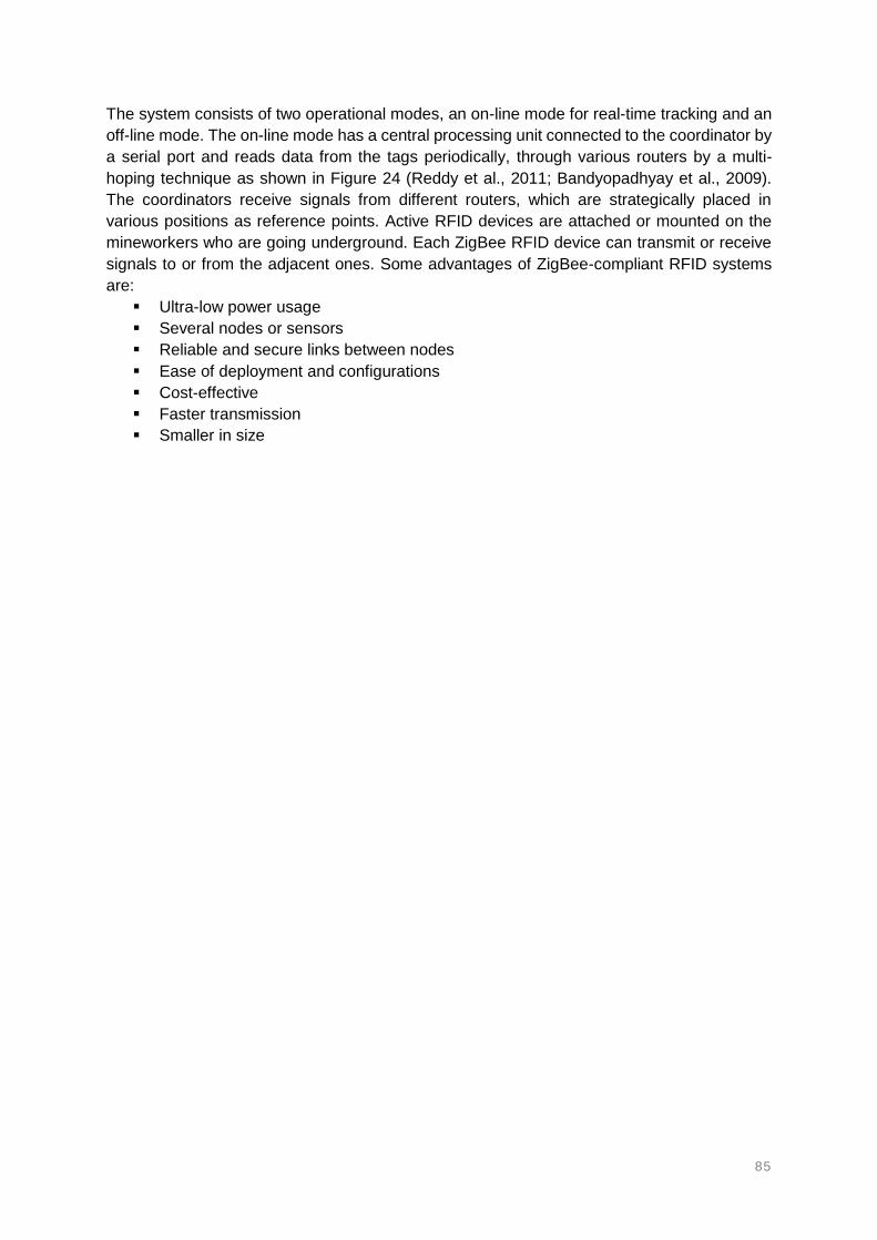
85
The system consists of two operational modes, an on-line mode for real-time tracking and an
off-line mode. The on-line mode has a central processing unit connected to the coordinator by
a serial port and reads data from the tags periodically, through various routers by a multi-
hoping technique as shown in Figure 24 (Reddy et al., 2011; Bandyopadhyay et al., 2009).
The coordinators receive signals from different routers, which are strategically placed in
various positions as reference points. Active RFID devices are attached or mounted on the
mineworkers who are going underground. Each ZigBee RFID device can transmit or receive
signals to or from the adjacent ones. Some advantages of ZigBee-compliant RFID systems
are:
Ultra-low power usage
Several nodes or sensors
Reliable and secure links between nodes
Ease of deployment and configurations
Cost-effective
Faster transmission
Smaller in size

86
Figure 24: ZigBee technology - mine personnel tracking system and infrastructure for underground mining applications
(Reddy et al., 2011)

87
ZigBee-compliant devices form a network system amongst themselves. The positions or
locations of persons are displayed numerically or graphically on display unit of the system.
The tracking data is stored and saved automatically by the system. The ZigBee tracking
system does not only detect the locations of personnel, but also provides the complete path
of that particular person being tagged. The system consists of an attendance records
monitoring aspect, which records the times going in-and-out of the mine for each person.
The ZigBee system consist of a monitoring computer, coordinator, router and an end device
(the tag). The computer is connected to the coordinators through cables, the routers are
connected to the coordinators wirelessly at a distance approximately 60m apart. A number of
routers are connected to each other at about 50m intervals. The tags are carried by the
mineworkers and communicate with the routers wirelessly. According to Reddy et al (2011)
and Bandyopadhyay et al (2009) the system capabilities of ZigBee active RFID technologies
are:
Tracking and monitoring the locations of mine personnel and mobile equipment in
underground mines. ZigBee-enables tags and carried by mine personnel and mounted
on equipment to report location to ZigBee readers that are strategically placed around
the mine.
Identification of mineworkers at shaft entry in order to keep track and monitor personnel
attendance.
Mobile equipment monitoring for enhanced productivity and collision avoidance.
Locating of mine personnel during and after the occurrence of accidents to speed up
rescue operations.
Provide early warning.
Provide real-time monitoring of atmospheric environment conditions of underground
mines.
Allows sending of coded messages to underground mine workers.
Enables the creation of networks amongst the undisturbed and reachable routers in
the case of accidents.
Applicable in surface mining operations.
Enables a low powered - intrinsically safe,
Ease of installation and cost-effective information to enhance the safety of mine
personnel.
2.3.6. A COMPARISON OF WI-FI, BLUETOOTH AND ZIGBEE
Wireless communication technologies in underground mining have been undergoing approval
processes conducted by the MHSA and has since then been installed in mines around USA.
Wireless communication is seen as the future technology for underground mines, not only in
the context of safety, but also has a productivity aspect. Wireless technologies have their
specific limitations and capabilities.
The applicability of wireless technologies has been studied extensively due to the dynamic
conditions of underground mining environments. Wireless technologies work very well in open
spaces, but face a number of challenges when used in underground mines. The drive behind
Wi-Fi, Bluetooth, ZigBee and other wireless systems is the fact that wired communications
can be easily damaged by flooding, explosions and rock collapse (Radinovic and Kim, 2008).
Table 10 shows a brief summary of the comparison of Wi-Fi, ZigBee and Bluetooth wireless
technologies.

88
Table 10: Comparison between Wi-Fi, ZigBee and Bluetooth technologies in the context of tracking mine personnel in underground mines (Bandyopadhyay et al., 2010)
Technology Wi-Fi ZigBee Bluetooth
Standard IEEE 802.11a, b and g IEEE 802.15.4 IEEE 802.15
Reach distance
(m)
50 - 100 10 - 100 10 – 100
Data rate 11 and 54 Mbps 250 kbps 1 Mbps
Frequency
bandwidth
2.4 GHz or 5 GHz 2.4 GHz 2.4 GHz
Power
consumption
High Ultra-low Medium
Topology or
type of
communication
Point to hub Ad hoc, mesh and
peer-to-peer
Ad hoc
Complexity High Low Medium
Applications Wireless LAN
connectivity,
broadband Internet
access
Industrial control and
monitoring, sensor
networks, automation
Wireless connectivity
Wi-Fi and Bluetooth communication technologies provide high data rate communication when
compared to other WSN systems such as near field communication (NFC) and ZigBee
technologies. However, Bluetooth has a widely limited reach distance. NFC is another form of
RFID wireless communication between devices. This system is usually used for access cards
applications. It is also widely used in the automotive industry (Steffen et al., 2017). It is very
short-range, fast, low power and secure communication method (DeLisle, 2014). The
technology allows very fast exchange of small amounts of data, which can only be activated
within very close proximity of devices.
All NFC standards are limited to 424 kbps data rate (DeLisle, 2014). This technology has been
evolving over the last decades with a purpose to support a wide scope of industries such as
the retail and smartphones industries. NFC technology uses peer-to-peer communication
between the connecting devices. The NFC devices can act as both a reader and a tag. This
allows NFC technology to read and interact with passive NFC tags, as well as passive high
frequency RFID tags that are compliant with ISO 15693. There is slight indication of near-field
communication technology used in the mining industry. Figure 25 compares the data rates
and distance of reach of the different communication technologies.

89
Figure 25: Data rate versus reach range comparison of different types of data transmission technologies (DeLisle, 2014)
2.3.7. INERTIAL NAVIGATION TRACKING SYSTEM
Inertial navigation systems are used to provide locations of missing persons in areas were Wi-
Fi, RFID, GPS and other technologies or systems are not applicable. Inertial navigation
systems use an Inertial Navigation Units (INU) to detect motion of objects such as
acceleration, rotations or any changes in magnetic fields when there is a change in position.
These systems are used for various applications such as surveying, automation and
positioning (Belyaev, 2017; Reid et al., 2012; Fan et al., 2014).
The inertial navigation systems can also provide guidance to mobile objects such as dump
trucks using their inertial sensors (Reid et al., 2012). Fan et al (2014) discuss how inertial
systems are used for mining machinery positioning in underground mines. According to
Svensson (2015), the inertial navigation system can be used to trace the locations of missing
people in underground mines following the occurrence of accidents. The motion of the missing
person is monitored by separate sensors that monitor motion and rotation in each of the X; Y;
Z coordinates axes of the object.
The system makes use of an accelerometer and a gyroscope (Svensson, 2015). The
gyroscope is a rotation motion sensor and the accelerometer measure linear acceleration. The
sensors have become smaller in size with low power consumption with continued
modernization. The inertial navigation technology is based on micro-electromechanical
systems (MEMS). The rescue team is issued with tracking devices during an emergency. The
performance inertial navigation can be improved by external aiding, such as adding velocity
sensors as shown in Figure 26.

90
Figure 26: Mechanism of the inertial navigation system using the gyroscope and accelerometer sensors (Reid et al., 2012)
Figure 26 also shows the process of locating missing persons by inertial navigation requires
initialisation and orientation from a known starting point of location. The miner starts moving
from a known location, the system interprets readings from the sensors, and then the readings
are integrated and interpreted to determine any changes in motion. Inertial navigation
technologies are independent of mine infrastructure.
The location of the missing person is determined solely from position changes relative to the
known initial location. However, the location data is processed by the INU device which is
carried by the miner. The location data or information in the INU device must then be relayed
to the control room on surface. The information can be linked to the backhaul system through
its own transmitter or an interface to a radio carried by the missing person.

91
One of the challenges of inertial navigation is the capability to maintain accuracy over time
(Reid et al., 2012). Minor errors accumulate within several minutes and meters, and may
become significant over extended periods of use. The errors are dependent and vary with the
movements of the missing person. These errors can be minimized and corrected by correlating
the INU device with a mine map. This is because the location of the missing person will be
limited to development ends and cross-cuts.
According to Svensson (2015), the accuracy of inertial navigation can be improved in various
methods such as adding the trilateration concept. The errors can be further reduced by
frequent re-initializing the system to a known location. The re-initialized location can be
obtained from the mine map and surveyed points. Another challenge with the location
accuracy of the system is associated with dynamic environments. The INU device may
misinterpret other shaky movements from the miner and distort it as the true motion and
location of the miner.
2.3.8. WIRELESS MESH NETWORKS
Mesh network systems consist of a series of interconnected node-readers that communicate
with one another through a multi-hop communication path (Griffin et al., 2010). Two or more
node-readers are required to create a network. Data, which is transmitted in the form signals,
is relayed through the interconnected node-readers, wirelessly. The node-readers
communicate with one another in distributing data in the network system.
According to Douglas (2014) the mesh network system makes use of signal-relaying points
that are strategically placed around the mine. The signal transmission points (node-readers)
communicate with end devices (handheld radios or tags) through wireless connection. Every
node-reader can exchange signals with any other reader. This is possible provided that there
are no obstacles restricting signal propagation and transmission. All the node-readers can
communicate with one another in an ideal situation, which is defined by a full-mesh system
(Novak et al., 2009), shown in Figure 27.
Figure 27: Types of mesh network connectivity configurations (NIOSH, 2013)

92
Figure 27 also shows the other various types of mesh network systems. The mesh network
consists of various connectivity paths. The connectivity path shows the signal propagation
path. Mesh networking with routing, a message-containing signal is propagated along a path
by hopping from one node to another (Wi-Fi or ZigBee connected node-readers) until it
reaches its destination. The mesh network systems are capable of transmitting high capacity
data in the air (Laliberte, 2009). This communication system benefits from the advantages of
both TTW and TTA communication techniques. This creates a better network coverage range
of the communication system for underground mining environments (Griffin et al., 2010;
Ranjan and Sahu, 2014).
Wireless mesh network systems are capable of re-establishing connectivity when some
portion of the system has been damaged. After an accident, the remaining part of the system
will continue to function (Forooshani et al., 2013). This is one of the biggest interests towards
tracking applications, as well as two-way voice, integrated into wireless LAN, fibre optic or
leaky feeder backbone infrastructure.
According to Douglas (2014) wired and wireless mesh systems have their own disadvantages
and advantages. However, a combination of the two mesh network systems can be used to
benefit from the advantages of each. The wired mesh system makes use of coaxial or fibre
optic cables while the wireless mesh networks makes use of radio frequency and Wi-Fi signal
access points (Douglas, 2014; Griffin et al., 2010).
In underground mining applications, mesh network systems utilise medium frequency and
ultra-high frequency propagation between node-readers. Data is relayed or propagated on a
direct node-to-node communication basis as an option to the wired network system. The node-
readers can continuously communicate with any other available node-reader, only if it is within
coverage range and this allows continuous connectivity. An example of a mesh network is
shown in the following section.
MINE SITE TECHNOLOGIES WIRELESS REPEATER NODE
Mine Site Technologies (2017) recently developed a wireless mesh network technology called
the wireless repeater node (WRN). This technology enables Wi-Fi network connectivity in all
parts of a mine. The system makes use of node-readers that are wirelessly connected to one
another. The wireless mesh network technology extends the existing Wi-Fi connection
underground. This becomes very essential in areas where power and data infrastructure are
impractical or challenging to install and extend. The node-readers of the WRN are battery
powered and can provide up to 120 hours of operational time. A demonstration of how the
node-readers communicate with one another is shown in Figure 28.
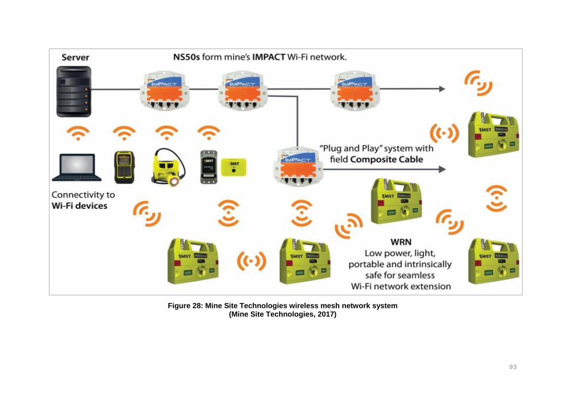
93
Figure 28: Mine Site Technologies wireless mesh network system (Mine Site Technologies, 2017)

94
2.3.9. POSITIONING AND LOCALISATION TECHNIQUES OF TTA SYSTEMS
TTA communication systems make use of five positioning techniques for localisation (Bouet
and Dos Santos, 2008). The techniques are based on the signals transmitted between a
sender and a receiver. These are the; received signal strength (RSS), time of arrival (TOA),
time difference of arrival (TDOA), and received signal phase (RSP). Table 11 summarises the
mechanisms of the different techniques. The propagation of radio waves in underground
mining environments is subject to various challenges that include severe multipath, limited
line-of-sight, absorption, diffraction and reflection:
Table 11: Mechanisms of signal interpretation for positioning
(Bouet and Dos Santo, 2008)
Localization
technique
Description
RSS The attenuation of signal strength is a function of the distance between
the transmitter and the receiver. The tag in proximity is localized with a
minimum of three reference points and the corresponding signal path
losses due to propagation. This algorithm is based on the difference
between the transmitted and received strength of the signals.
TOA The distance in between a reference point and the target tag is
proportional to the propagation time of the signals. The transmitters and
receivers must be precisely synchronized in order to yield accurate
distances estimations. The transmitted signals must include timestamps
to enable accurate evaluation of the travelled distance.
TDOA This principle depends on the relative location of the target tag by
measuring the difference in the time in which a signal was emitted and the
time the signal arrives at the reader. An intersection between three fixed
receivers gives an estimated location of the tag.
RSP This principle uses the delay during signal transmission which is often
expressed as a fraction of the wavelength of a signal to estimate distance
apart.

95
2.3.10. SIGNIFICANCE OF AVAILABLE INFORMATION (2.3.1 – 2.3.9)
A comparison of the TTA communication systems is summarised in Table 12 which will be
carried over to the results section (Chapter 4). The systems have potential applications for the
underground mining environments. Table 12 describes the functionalities, capabilities and
limitations of the different types of TTA communication systems and these are applied in the
results section (Chapter 4). Table 12 shows that all these systems have the potential to be
used in underground mining. However, certain systems are more suitable than others in
certain conditions.
TTA communication systems are mostly associated with tagging and tracking systems, which
often operate on the medium frequency (MF) band. Two-way voice, and tagging and tracking
technologies (tags and readers) provide wireless tracking systems that detect positions of
mine personnel in real-time. Various manufacturers are offering two-way voice, tagging and
tracking systems for underground mining applications.
These systems, from the various manufacturers may use a similar concept (communication),
but have different capabilities and limitations. TTA communication systems are mainly divided
into:
TTA two-way voice communication
o Handheld radio units
TTA passive RFID tagging and tracking
o Passive RFID
TTA active RFID tagging and tracking
o RFID tagging
o Wi-Fi
o ZigBee
o Bluetooth
o Inertial navigation
o Mesh network
o Underground GPS
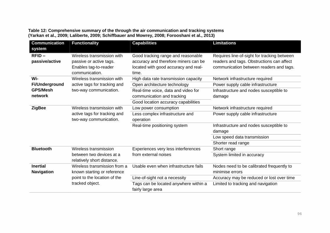
96
Table 12: Comprehensive summary of the through the air communication and tracking systems (Yarkan et al., 2009; Laliberte, 2009; Schiffbauer and Mowrey, 2008; Forooshani et al., 2013)
Communication
system
Functionality Capabilities Limitations
RFID –
passive/active
Wireless transmission with
passive or active tags.
Enables tag-to-reader
communication.
Good tracking range and reasonable
accuracy and therefore miners can be
located with good accuracy and real-
time.
Requires line-of-sight for tracking between
readers and tags. Obstructions can affect
communication between readers and tags.
Wi-
Fi/Underground
GPS/Mesh
network
Wireless transmission with
active tags for tracking and
two-way communication.
High data rate transmission capacity Network infrastructure required
Open architecture technology Power supply cable infrastructure
Real-time voice, data and video for
communication and tracking
Infrastructure and nodes susceptible to
damage
Good location accuracy capabilities
ZigBee Wireless transmission with
active tags for tracking and
two-way communication.
Low power consumption Network infrastructure required
Less complex infrastructure and
operation
Power supply cable infrastructure
Real-time positioning system Infrastructure and nodes susceptible to
damage
Low speed data transmission
Shorter read range
Bluetooth Wireless transmission
between two devices at a
relatively short distance.
Experiences very less interferences
from external noises
Short range
System limited in accuracy
Inertial
Navigation
Wireless transmission from a
known starting or reference
point to the location of the
tracked object.
Usable even when infrastructure fails Nodes need to be calibrated frequently to
minimise errors
Line-of-sight not a necessity Accuracy may be reduced or lost over time
Tags can be located anywhere within a
fairly large area
Limited to tracking and navigation

97
2.4. COMMERCIALLY AVAILABLE TAGGING AND TRACKING AND TWO-WAY
COMMUNICATION SYSTEMS
This section discusses systems that are commercially available. These systems are based on
the TTA communication technologies. The TTA communication systems discussed in this
section includes both tagging and tracking systems as well as two-way communications
systems. This section also covers systems manufactured and used in different countries
worldwide. There are several manufacturers available in the market and this study discusses
some of the commonly used systems as advertised on company websites, product brochures
and other relevant online reports.
2.4.1. IDENTIFIED SYSTEMS
The systems may have similar functions, but have different capabilities and limitations. This
section will also discuss the infrastructure that is required to operate these systems. The type
of infrastructure will highlight the main components of the systems and how these components
are installed underground. The installation of the components takes into considerations factors
such as spacing of readers. This section further explains how the systems are installed
underground for the purpose of locating missing persons.
MINE SITE TECHNOLOGIES
Mine Site Technologies (2017), known as MST Global specialises in communications,
proximity detection, vehicle and people tracking solutions for the mining industry. MST Global
provides a wide range of communications and tracking technologies for tracking and locating
missing persons in underground mines. The system is not only for tracking personnel, but also
assets and mobile equipment. The system is capable of reporting the real-time locations of
miners as they work and travel underground as shown in Figure 29.
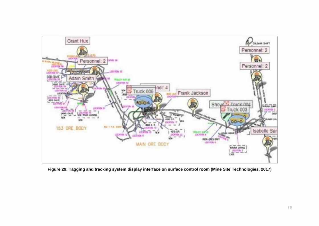
98
Figure 29: Tagging and tracking system display interface on surface control room (Mine Site Technologies, 2017)

99
The MST tagging and tracking system makes use strategically placed (within the mine) Wi-Fi
access points and node-readers. The readers are installed against the hangingwall as shown
in Figure 30. The readers detect active RFID tags that are within read range and report the
tags as the location of the person carrying the tags. The system has a read range of 60 to
120m in typical underground mining environments. The data obtained from the system is
reported and monitored in a control room located on surface. The tagging system does not
only report the exact locations of mine personnel, but can also be used various other features
such as fleet management and production control (asset utilisation).
The tags and node-readers, and access points operate in the 2.4 GHz frequency bandwidth
in which signals can be propagated for significant distances with accuracy and reliability in
underground environments. The backbone infrastructure comprises of Wi-Fi network that
provides reliable, mobile and high-performance data communication structure capable of
withstanding underground mining environments. The access points can be configured in a
single radio technique that detects the presence of tags only, or configured with two radios for
tag presence detection and directional antennas to determine direction of movement.
Figure 30: Wi-Fi access point installed in an underground mine to provide network coverage (Mine Site Technologies, 2017)
MST also provides a voice communication function for two-way voice communication. The
voice communication systems use either leaky feeder connections or Voice over Internet
Protocols (VoIP) technologies. Voice communication is provided by portable handset units,
called the MinePhone. The handsets are capable of making and receiving calls while in areas
with wireless network coverage. The handsets are IEEE 802.11b/g compliant for Wi-Fi
connectivity. The MinePhone can also send private messages to other phones.
The phones are generally lightweight measuring 250g with battery life of 14 hours, sufficient
to last the whole shift. The phone can also act as a tag to enable tracking. Data transmission
is provided by a wireless LAN data network based on rugged fibre optic, wired and wireless
networks. This allows high bandwidth network to support large data for video, voice and data
transmission. The phone is designed to be intrinsically safe due to the threats of explosive and
toxic gases underground. The phone is capable of private, person-to-person phone calls.

100
BECKER MINING SYSTEMS TAGGING AND TRACKING
Becker Mining Systems (2017) is a designer, manufacturer and supplier of various
underground mining services including communication and tracking systems. Becker Mining
developed a tagging and tracking system that enables the tracking of personnel, vehicles and
assets throughout the underground mining environment. The system comprises of an active
tag, the BECKERTAG, which transmits uniquely coded signals to tag readers. The tag readers
are strategically place in the mine and transmit the tagging data to a centralised database on
surface.
The tag readers can distinguish between personnel, vehicles and assets. The tag readers
utilise the RSSI algorithm to better the accuracy of positioning. The tag readers are connected
to one another over fibre optic cables, RF transmission or Wi-Fi based. The readers
communicate with the tags wirelessly. Figure 31 shows some of the components of the tagging
and tracking system. The components include the surface display unit, node-readers as well
as the end devices (tags, handheld radios and sensors).
Figure 31: Tagging and tracking system developed by Becker mining using BECKERTAGS (Becker Mining South Africa, 2017)
All mine personnel and vehicles are equipped with tags. The tags transmit unique identification
coded signals to node-readers at an approximately one-second interval. The tags and readers
communication have a read range of about 200m with minimal transmission time to avoid
collision of multiple tags.

101
The tags are designed to fit most commercial cap lamps available in the market. The tags are
then powered by the cap lamp battery to actively transmit signals. Alternatively, a tag that
contains a Lithium battery is available. Becker Mining uses leaky feeder, fibre optic cables or
Wi-Fi Ethernet (Figure 32 - 34) as the backbone communication system. This is advantageous
in mines that may already have either of these infrastructures in place, but maybe used for
other applications besides tracking.
Figure 32: Becker Mining backbone infrastructure using radiating cables to provide coverage (Becker Mining, 2017)
Figure 33: Becker Mining backbone infrastructure using fibre optic and copper cables to enable underground network (Becker Mining, 2017)

102
Figure 34: Becker Mining backbone infrastructure using Ethernet and Wi-Fi to enable underground coverage (Becker Mining, 2017)
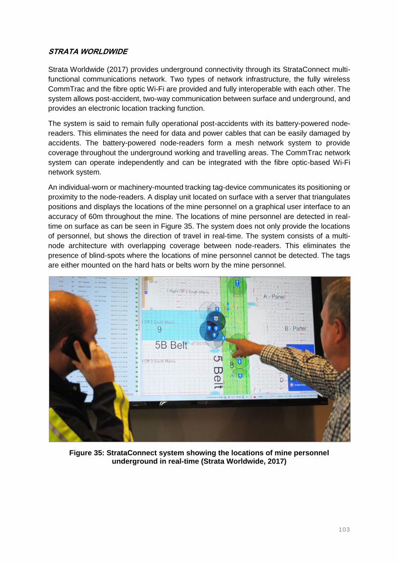
103
STRATA WORLDWIDE
Strata Worldwide (2017) provides underground connectivity through its StrataConnect multi-
functional communications network. Two types of network infrastructure, the fully wireless
CommTrac and the fibre optic Wi-Fi are provided and fully interoperable with each other. The
system allows post-accident, two-way communication between surface and underground, and
provides an electronic location tracking function.
The system is said to remain fully operational post-accidents with its battery-powered node-
readers. This eliminates the need for data and power cables that can be easily damaged by
accidents. The battery-powered node-readers form a mesh network system to provide
coverage throughout the underground working and travelling areas. The CommTrac network
system can operate independently and can be integrated with the fibre optic-based Wi-Fi
network system.
An individual-worn or machinery-mounted tracking tag-device communicates its positioning or
proximity to the node-readers. A display unit located on surface with a server that triangulates
positions and displays the locations of the mine personnel on a graphical user interface to an
accuracy of 60m throughout the mine. The locations of mine personnel are detected in real-
time on surface as can be seen in Figure 35. The system does not only provide the locations
of personnel, but shows the direction of travel in real-time. The system consists of a multi-
node architecture with overlapping coverage between node-readers. This eliminates the
presence of blind-spots where the locations of mine personnel cannot be detected. The tags
are either mounted on the hard hats or belts worn by the mine personnel.
Figure 35: StrataConnect system showing the locations of mine personnel underground in real-time (Strata Worldwide, 2017)

104
Strata Worldwide recently developed a Cordless tracking cap-lamp that integrates people
tracking and two-way communication systems. The light emitting diode (LED), cap lamp is
specifically designed for underground mining applications. The cap lamp has a built in blue
flashing LED notification for alerting mine personnel, a dual-function button for on/off, and a
panic button. A tracking tag is integrated into the cap lamp of the mine personnel entering
underground. The tags comprise of 12 primary and 24 secondary hours long lasting battery,
which can be recharged for 5 hours after shift hours. The tags have an operating temperature
ranging between 0 and 45 degrees Celsius.
MINELERT
Minelert (2017) has developed the Lost Persons Detection (LPD) for underground mining
applications. The system consists of an Ethernet backbone network infrastructure, a Master
controller, Tag controller, active Tags and LPD Scanning unit. The Ethernet backbone network
infrastructure together with its fibre optic cables is used for data transmission between
underground and surface.
The system provides Wi-Fi coverage for various types of mines, including the deep level mines
of South Africa. The Master controller is the database of the system. The tag controllers,
commonly referred to as the node-readers are located and installed in zonal areas where
people are expected to work and travel.
The readers are connected to the network via the Power over Ethernet (PoE) IEEE 802.3
Ethernet or the IEEE 802.11 Wi-Fi interfaces. Active tags are carried by the mine personnel
and communicate with the readers within the 2.4 GHz frequency band. The tags are also
equipped with a 13.5 MHz interface used for near-field authentication as well as tag activation.
The tags have a battery that can last for over 6 years through its utilisation of ultra-low power
technology. The battery lifespan is achieved by a four-second beacon interval transmission.
The system and its components are shown in Figure 36.
Figure 36: Minelert Lost Person Detector system for underground mining
(Minelert, 2017)

105
Minelert Tag Controller (node-readers): The node-readers are strategically placed around the
mine where they can detect the presence of tags within proximity. The readers are placed
starting from the mine lamp rooms, at the underground stations, waiting areas, refuge
chambers and through to the crosscuts. The readers continuously transmit 2.4 GHz signals.
It supports a dual scanning interface that improves the range and accuracy for sensing. The
node-readers also provides store-and-forward technology that enables the system to continue
tracking even if it has been disconnected from the network for up to 3 weeks. The system uses
Ethernet or Wi-Fi interfaces for underground network coverage.
Minelert Active Tag (tags): The tags operate within the 2.4 GHz frequency bandwidth
transmitted by the Minelert Tag Controller. The tags can also be developed to detect for
temperature and gas levels if needed by the client. The system also consists of LPD scanning
units used in search-and-rescue operations conducted by rescue teams.
The system is implemented in the underground hard rock mining industry by AngloGold
Ashanti and Harmony Gold:
Mponeng Shaft: 8000 LPD tags, 1000 Material Car Monitoring tags,
Moab Khotsong Shaft: 7400 LPD tags, 1000 Material Car Monitoring tags,
Kopanang Shaft: 1000 Material Car Monitoring tags,
Tau Tona Shaft: 1000 Material Car Monitoring tags, and
Doornkop Shaft: 1000 Material Car Monitoring tags.
The LPD system is a proximity (zoning) solution and is based on 2.4 GHz technology. The
LPD system was designed to overcome the challenges found in Real-Time Location System
(RTLS) technology within mining applications:
Reliable tracking information. Numerous Radio Frequency technologies (433 MHz,
868 MHz) were scientifically tested during development and it was proven that 2.45
GHz has the best propagation characteristics for reliable and repeatable tracking
accuracy.
Ease of installation and implementation. The reading range is fully adjustable from 1m
up to 200m. No need for any RSSI site surveys. Tags are independent of any electrical
subsystem and can be retrofitted to most target devices.
Superior battery life. Guaranteed battery life of over 6 years can be achieved on a 4-
second beacon interval.
No complicated tag license agreements are required.

106
INNOVATIVE WIRELESS TECHNOLOGIES
Innovative Wireless Technologies (IWT) (2017) provides the Sentinel and Accolade wireless
communication and tracking systems. The system makes use of tags and mesh networks for
tracking personnel in an underground mining environment. The mesh network system is
formed from antennas and beacons. The beacons are mounted and strategically placed
around the mine and the mine personnel carry the tags.
The system operates from a completely wireless infrastructure. The system is capable of
providing two-way voice, texting and tracking using a single handset. The system transmits
data through wirelessly connected beacons and antennas. The beacons are battery-powered
and consist of a battery-backup unit for long lasting power supply. The major components of
the system are shown in Figure 37 and Figure 38.
Figure 37: The IWT Sentinel system components for coal, hard rock mining and tunnelling (Innovative Wireless Technologies, 2017)
Figure 38: The IWT Accolade system components for coal, hard rock mining and tunnelling (Innovative Wireless Technologies, 2017)

107
MINETRACKER
Venture Designs and Helicomm collaborated and designed the MineTracer Miner Location
Monitoring system (Fiscor, 2008; Business Wire, 2008). Fiscor (2008) gives an update on the
available communications and tracking systems for underground mining. The system has
various features such as mine personnel tracking and two-way wireless communication based
on ZigBee technology. The system uses wireless mesh network, which was mainly selected
for its low power consumption and large monitoring and control area. However, the system
possesses low data rates. The low data rates were traded-off with the low power consumption,
which enables battery backup options.
The MineTracer system opts to use many small readers instead of trying to overcome
obstacles by increasing power for driving signals. This is because high power consumption
may become intrinsically unsafe. The readers are strategically placed around the mine and
become fixed access points with a read range close to 320m apart (Fiscor, 2008). The ZigBee
readers do not only act as access points but also relay nodes that seek an alternative path out
of the mine in case of an emergency. The access points are built with a battery backup that
lasts for 48 hours, extendable to 96 hours. The mine personnel carry tags that wirelessly
communicate with the readers.
NORTHERN LIGHT TECHNOLOGIES TRACKING AND LOCATION SYSTEMS
Northern Light Technologies (NLT) (2017) offers a Wi-Fi and RFID real time tracking system
for personnel working in underground mines. Digital Wi-Fi tracking makes use of tags that are
mounted and integrated into the cap lamps of the mine personnel and Wi-Fi access points are
used as node-readers for the detection of tags that are present within range. The tracking of
mine personnel is recorded in a software located in a control room on surface. Active RFID
tracking and location system is also used for tracking mine personnel. NLT also offers two-
way radio communication systems. The two-way radio phone allows mine personnel to talk
and text each other from underground. The phones are connected to the Wi-Fi.
PBE TAGGING AND TRACKING SYSTEM
PBE Group (2017) provides a real-time tagging and proximity tracking system. This system
identifies the locations of personnel and equipment equipped with long range RFID
transponders. The system comprises of stationary and portable tag readers distributed around
the underground workings. The wireless and wired tag readers can transmit data over either
leaky feeder systems or existing network infrastructure.
The components of the system (Figure 39) include long range RFID transponders, RFID
reading stations, positions markers, underground antennas, handheld units, RFID activation
and deactivation stations, and information display unit. PBE Group uses leaky feeder systems
for radio coverage and data communication.
The PBE tagging and tracking system enables the control room operator to know who, what,
when and where of all underground mine personnel at all times, as shown in Figure 40. The
tags issued to the mine personnel are connected into the cap lamps. The tags use RFID, GPS,
and electromagnetics and radar technologies to detect the real-time locations of mine
personnel. The tags are also compatible with proximity alert systems.
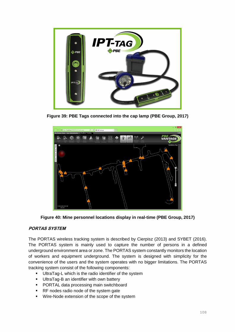
108
Figure 39: PBE Tags connected into the cap lamp (PBE Group, 2017)
Figure 40: Mine personnel locations display in real-time (PBE Group, 2017)
PORTAS SYSTEM
The PORTAS wireless tracking system is described by Cierpisz (2013) and SYBET (2016).
The PORTAS system is mainly used to capture the number of persons in a defined
underground environment area or zone. The PORTAS system constantly monitors the location
of workers and equipment underground. The system is designed with simplicity for the
convenience of the users and the system operates with no bigger limitations. The PORTAS
tracking system consist of the following components:
UltraTag-L which is the radio identifier of the system
UltraTag-B an identifier with own battery
PORTAL data processing main switchboard
RF nodes radio node of the system gate
Wire-Node extension of the scope of the system

109
SAZU TECHNOLOGIES
Sazu Technologies (2017) offers an underground communication, and a tagging and tracking
system. This technology is based on underground Wi-Fi network technology. The main focus
of this system is to track mine personnel, but can also integrate other features such as sensors
and asset monitoring functions. The system comprises of tags, Wi-Fi enables access points
as readers, information servers as well as a display software unit. The software continuously
updates the locations of tags detected by the readers. Not only are the locations of mine
personnel reported, but also the number of personnel inside and outside the mine.
The software displays the name of the tag holder, the time and location of the person. The
mine personnel are required to carry the tags with them at all times. The tags and readers
interact and communicate with each other in order to effectively provide the locations of
trapped persons to surface. The locations are detected in real-time. The tag and reader
communication have a range of 100-150m apart at a frequency of 125 kHz. The readers
transmit the tagging information to surface through Ethernet network in the mine. The
information is relayed to surface control room by fibre optic cable infrastructure. Figure 41
shows how data is relayed to surface from underground.
Figure 41: Tagging and tracking system amongst other systems integrated in the backbone infrastructure (SAZU Technologies, 2017)
MATRIX METS 2.1 SYSTEM
The METS (Miner and Equipment Tracking System) system provides wireless communication,
electronic tracking and atmospheric monitoring features (Matrix Design Group, 2017). The
system is said to be designed specifically for survivability and post-accident functioning in
underground mining environments. The system comprises of intrinsically safe, tracking tags
and atmospheric sensors connected through coaxial cables or by means of wireless
transmission.

110
AN UNDERGROUND-GPS SYSTEM BY MINETEC
The Minetec tracking system replicate the concept of trilateration as used in global positioning
system to provide coordinates and real-time tracking similar to that of the GPS (Minetec,
2017). The system requires at least three node readers to establish GPS-like motion tracking.
The node readers can be battery powered to enable wireless communication. Figure 42 shows
a typical underground map of tunnels and working areas where the system is installed. The
node-readers are installed throughout the mine where the miners are expected to work and
travel.
Figure 42: Minetec real-time coordinates tracking system for underground mining (Minetec, 2017)
MINESAFE SMARTWATCH
Vandrico Solutions collaborated with SAP Co-Innovation Lab and Illumiti to develop the
MineSafe Smartwatch capable of tracking mine personnel (Mining.com, 2015). The MineSafe
Smartwatch is designed to enable real-time communication between mine personnel trapped
underground and rescue teams on surface.
The watch provides a quick identification and prediction of potential hazards, provides urgent
notification (see Figure 43) to mine personnel of dangerous situations, identification of
locations of mine personnel during emergencies and provide safety guidance for evacuation.
The watch combines proactive and immediate features that can greatly assist with emergency
responses. The watch makes use of sensors and Wi-Fi to facilitate communications and
accelerate evacuation procedures.

111
Figure 43: MineSafe smartwatch (Mining.com, 2015)
I-WRIST SMARTWATCH DEVICE DEVELOPED
EasyM2M Technologies (2017) developed a Wi-Fi enabled wrist watch called the i-Wrist
smartwatch that enables Wi-Fi and Bluetooth connectivity. The watch is capable of enabling
real-time tracking and two-way communication between trapped miners and surface control
room. EasyM2M technologies also provides wireless mesh network for underground internet
connectivity at all times. The device also consists of gravity sensors that can detect trapped
and falling miners. The device records GPS coordinates and comprise of a 3 megapixels
camera for video calling. In addition, the smartwatch can measure and monitor the heart rate
and blood pressure. Some of these features are shown in Figure 44 of the interface of the
smartwatch.
Figure 44: EasyM2M smartwatch device for tracking, communication and (International Mining, 2015; Mining.com, 2015)

112
The Wi-Fi access points are strategically placed to create a sufficient mesh network for better
coverage. The Wi-Fi access points automatically detect the locations of the mine workers and
report the locations to the control room on surface in real-time. The wireless mesh network
was selected to mainly eliminate the use of hard-wired connection and to increase
underground network coverage.
The device has a Skype application that can be used by trapped mine workers to video-call
with rescue teams in real-time. The video calling can be initiated either by the trapped person
or the rescue team. The trapped person can video-talk with doctors for mental and health
advice while rescue is underway. The device includes various other features such as gas
detection and monitoring integrated with the tracking and communication features. The watch
is designed to be waterproof, lasting over two hours when submerged under water. The device
has been tested at some Indian mines, as at the Eastern Coalfield Limited in Odisha.
2.4.2. SIGNIFICANCE OF AVAILABLE INFORMATION
Several suppliers of TTA tagging and tracking systems available in the market. Table 13
provides a summary of commercially available TTA tracking and two-way communication
systems. The systems are operated over various types of backbone infrastructures that
network coverage underground. This information will be used in the results section (Chapter
4) in terms of system capabilities. However, the specific systems (e.g. Mine Site Technologies,
etc.) from the suppliers will not be carried over to the results section in Chapter 4. This
information is for knowledge purposes and to show the availability of commercial systems that
can be implemented in the mines.

113
Table 13: Summary of TTA tracking and two-way communication systems
System/Supplier Backbone
infrastructure
Tracking capabilities
and limitations
Two-way
communication
TTR Locator function Auxiliary functions
MST Fibre optic Wi-Fi network
and mesh, leaky feeder
and VoIP
Tagging and tracking
with 60-120m read
range
Two-way voice
communication using
handsets
- Proximity detection for
collision avoidance,
mobile vehicle tracking
Becker Mining Leaky feeder cables, fibre
optic and Wi-Fi or
Ethernet connectivity
Tagging and tracking
with 200m read range
tags and readers
Two-way voice
communication using
handheld radios
- -
Strata Worldwide Fibre optic wireless
backbone
Tagging and tracking
with 60m accuracy
Provides two-way
communication
- Early warning and
panic button
Minelert PoE or Wi-Fi backbone
infrastructure
Tagging and tracking - LPD scanning unit -
IWT Mesh network backbone Tagging and tracking Two-way voice and
text on a single
handset
Locator unit Mobile vehicle and
assets tracking
Minetracer ZigBee wireless mesh
network
Tagging and tracking
with 320m read range
Two-way voice
communication
- -
NLT Wi-Fi network backbone Tagging and tracking Talk and text radio
phone
- -
PBE Group Leaky feeder backbone Tagging and tracking Two-way radio and
data communication
- Proximity warning
system
SYBET - Tagging and tracking - - Equipment tracking
Sazu Fibre optic or Wi-Fi Tagging and tracking
with read range of 100-
150m
- - Assets monitoring
Matrix Wireless mesh network
and coaxial cables
Tagging and tracking Two-way voice - Atmospheric
monitoring
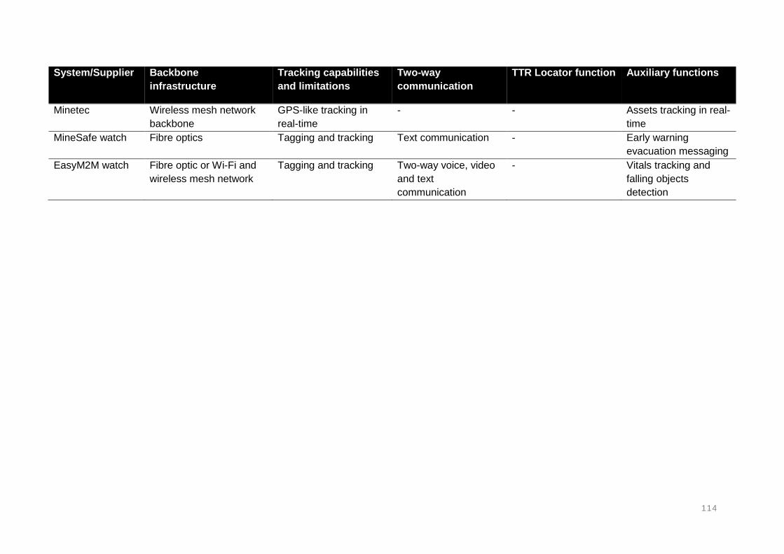
114
System/Supplier Backbone
infrastructure
Tracking capabilities
and limitations
Two-way
communication
TTR Locator function Auxiliary functions
Minetec Wireless mesh network
backbone
GPS-like tracking in
real-time
- - Assets tracking in real-
time
MineSafe watch Fibre optics Tagging and tracking Text communication - Early warning
evacuation messaging
EasyM2M watch Fibre optic or Wi-Fi and
wireless mesh network
Tagging and tracking Two-way voice, video
and text
communication
- Vitals tracking and
falling objects
detection

115
2.5. THROUGH THE EARTH TRACKING AND COMMUNICATION SYSTEMS
The most critical step during mine rescue operations is the quick and accurate location of
trapped mine personnel after an accident (Heasley and Shaw, 2014). Geophysical methods,
particularly seismic and electromagnetic wave systems, become the only available methods
for locating trapped mine personnel, as the primary systems can be severely damaged during
accidents (Heasley, 2012; Heasley and Shaw, 2014; Pronenko and Dudkin, 2016). TTE
communication methods are communication systems whereby a signal is propagated through
solid rock and soil using electromagnetic and magnetic waves at very-low to ultra-low
frequencies (Laliberte, 2009).
2.5.1. THE MECHANISM OF TTE SYSTEMS
The TTE communication technique enables rescue teams on surface to either detect or
communicate with trapped mine personnel underground in the mine (Kumar et al., 2003;
Barkand et al., 2006). TTE systems are usually one directional in terms of establishing
communications between surface and underground. TTE communication systems were
initially designed with a one-way (one-directional) communication feature, but recent versions
have the capabilities to enable two-way communication (Barkand et al., 2006; Ranjan and
Sahu, 2014; Pronenko and Dudkin, 2016).
TTE communications make use of ground conduction signalling, seismic wave signalling and
wireless signalling techniques to transmit signals between underground to surface
(Schiffbauer and Mowrey, 2006; Pronenko and Dudkin, 2016). Ground conduction signalling
makes use of injecting and receiving signals through interconnected rock layers. The distance
apart (overburden thickness or depth), water tables, conductive strata and others, are factors
that can affect the functionality and capabilities of TTE techniques.
Seismic signalling picks up rhythmic vibrations that are generated by the lost miner who starts
pounding against the roof, floor or roof-bolts in the mine (Kumar et al., 2003). Wireless TTE
communication systems now exist in underground environments. The TTE systems cannot be
easily damaged during accidents. This is because the systems do not make use of intensive
infrastructure (Pronenko and Dudkin, 2016). This plays a significant role in enhancing a
successful operation of the TTE communication systems (Heasley, 2012).
In an event where mine personnel managed to survive the initial accident, but became trapped
underground and their positions are unknown by the rescue teams on surface, locator systems
become the most crucial item. This is because the primary or standard communications and
tracking systems are usually damaged or interrupted by accidents, which also blocks passage
for the mine personnel remaining underground (Nessler, 2000). There arises the vital
importance of locating the trapped or missing mine personnel by means of an independent
method of finding missing persons, without relying on the primary systems.

116
Kumar et al (2003) describe the survival of mine employees underground during an accident
is a measure of a matter of minutes. The conventionally used early warning systems such as
horns and siren-alarms and text messages are usually too slow and ineffective to save
surviving mine employees. While the primary communication and tracking systems and
infrastructure fail or become damaged due to the occurrence of accidents, the locations of the
missing and trapped mine workers become unknown by the arriving rescue teams on surface
(Nessler, 2000). This has resulted in the need for a wireless, line-of-sight independent, ultra-
low frequency signalling system that will work through solid rock and independent of
communication infrastructure (Kumar et al., 2003).
Kumar et al (2003) notes that the currently existing technologies and systems such as
telephones, leaky feeder and optical fibre systems cannot meet all emergent requirements of
post-accident systems, especially in the event of mining accidents. The current systems fail
immediately in the event of an explosion, fall of ground and water inundation, and thus making
it difficult to locate and establish contact with the missing persons. As a result, the search-and-
rescue mission is affected and delayed significantly. Hence, the continued research projects
to improve TTE systems concerning signal processing, noise filtering, location accuracy and
other (Heasley and Shaw, 2014).
The consequences of all the challenges faced in locating trapped mine workers in the event
of an accident was focused on extremely low frequency communication and tracking systems
using the rock strata of the Earth as a medium to propagate radio wave signals (Kumar et al.,
2003). In addition, Maity (2015) believes that a perfect tracking system is one with the
capabilities to work through rock strata, collapsed or cave-ins grounds. Factors such as the
thickness of overburden, type of overburden material, surface obstructions, slope
characteristics, confinement, permissibility and portability are amongst some of the limitations
of this technology (Barkand et al., 2006).
According to Kumar et al (2003) ultra-low-frequency electromagnetic signals in the range of
630 Hz and 2 kHz can be propagated through the Earth up to about 1 600m to intrinsically
safe underground or surface receivers. There are mainly two types of TTE systems for
detecting and locating trapped persons in underground mining situations. These are the TTE
seismic wave and electromagnetic communication systems. The electromagnetic systems use
narrowband signalling while the seismic waves system senses vibrations created by a trapped
person. These systems provide coverage to various sections of the mine, with less chances
of damage during accidents as the antenna is located on surface. TTE technologies have
been limited to text messaging in the past because data rates at low frequencies are very poor
(Ranjan and Sahu, 2014).

117
2.5.2. TTE SEISMIC WAVES SYSTEM
Seismic waves systems consist of a network or array of geophones that are strategically
placed on the surface. The geophones must preferably be placed directly above the
underground workings where the trapped persons are located, or as close as possible. The
correct placement of the geophones creates a network that can detect seismic waves. The
seismic waves are created by a trapped miner, pounding or hitting the surrounding wall rock
of the underground workings. The resulting vibrations are detected on surface through the use
of transducers, sensometer or well known as geophones (Kumar et al., 2003).
The trapped mine personnel are required to pound the walls using a heavy object present in
the surroundings. These seismic waves, generated from the pounding travel to the surface
through rock as vibrations. The vibrations should be created at a particular pattern to transmit
unique vibrations. The geophones are responsible for converting the seismic signals to
voltages that can be amplified, filtered and recorded (Kumar et al., 2003). The seismic waves
are recorded in an array of geophone sensors on surface (Forney and Amartin, 2001). The
seismic system makes use of an array composed of several sub-arrays rather than the same
number of geophones in which the seismic signals are received (Kumar et al., 2003). This is
because the sub-array gives a better signal-to-noise ratio than a single geophone.
The location of the missing or trapped person, as the source of the seismic waves, is detected
using an analysis of travel time differences between the sensors or geophones (Forney and
Amartin, 2001). The resolution of the travel time difference of the seismic waves between the
source (point at which trapped person is pounding) and the receivers (geophone sensors) on
surface, is highly dependent on the strategic distribution of the sensors relative to the location
of the seismic wave source, as well as the choice of the velocity model (Forney and Amartin,
2001).
The seismic waves system consists of several subarrays of sensors, in which each subarray
consists of 7 or 24 geophones (Forney and Amartin, 2001). A single subarray can be sufficient
to identify seismic signals coming from a pounding mine personnel underground. More than
one subarrays are necessary for the identification of a more precise source of signals.
Locations identification requires at least three subarrays detecting common signals from the
same source of pounding. A minimum of five subarrays are required for a reasonable accurate
location of a trapped person.
The accuracy of the system is one of the crucial parameters, of any tracking or locator system,
as it serves to reduce the scale of search area in order to fast-track the rescue mission. The
seismic wave system requires a calculated or theoretic guess of the suspected area in which
the missing person is trapped. This will be guided by the knowledge or starting point in which
the accident occurred. The accuracy of seismic waves systems is characterised by the seismic
source in relation to the geometrical sensor arrays. The accuracy of seismic waves systems
varies between a sub-meter point to several meters (Forney and Amartin, 2001).
The geophones operate within the 28 Hz and 1 kHz frequency range, which falls under the
ultra-low frequency band (Forney and Amartin, 2001). One of the biggest effects of the system
is external noises. However, seismic waves systems are designed to eliminate external noises
from the signals transmitted from the pounding mine personnel. The geophone probes are
deployed to the site in which mineworkers are suspected to missing or trapped in the
underground workings.

118
The geophone probes are inserted in a 50mm diameter borehole that is between 5 and 10m
deep (Forney and Amartin, 2001). An analogous signal is transmitted to the acquisition unit
through cable connections on surface. The acquisition unit comprise of a noise-filtering device
that eliminates noise interferences from the system. The number of sensors responsible for
triggering seismic wave signals can be firstly tested in accordance with the environmental
interference. The detection of trapped mine personnel using the seismic waves system
depends on:
The number of sensors deployed on surface to listen for signals
The strategic placement or geometry of the geophones inserted on boreholes on
surface
The accuracy of velocity models
The conditions of the rock strata in which the seismic waves have to travel through
The seismic waves system has been extensively studied in the past (Heasley and Shaw,
2014). Heasley and Shaw (2014) conducted tests on the system to determine the capabilities
and limitations of the system under various geological and mining conditions. Various micro-
seismic systems or manufacturers have been assessed to fulfil the needs of a mine rescue
operation (Heasley et al., 2007; Heasley and Shaw, 2014). The system uses geophones to
detect ground waves generated by trapped miners who are pounding from an underground
location. The system required that the signals created from the pounding must exceed
background noises from the mine environments (Heasley and Shaw, 2014).
During testing of the system, signals were not detected from depths where the background
noise was larger than the signals generated from the pounding. This created the need for a
filtering system that would clean background noises from the signals. The strategic placement
of the geophones relative to the location in which the trapped miner is pounding was a crucial
factor in developing the system. It was realised that the geometry of the sensor-arrays should
preferably be in-line with the geometry of the gallery where the trapped persons are located
in order to overcome the background noises.
Maximum accuracy of the location of the trapped miners is obtained when the miners are
pounding the sidewalls of the tunnels facing the sensors (Forney and Amartin, 2001). The
accuracy is therefore limited when pounding the walls facing an opposite direction to the
sensors. In the event of an emergency where a miner becomes trapped underground, the
following procedure is followed:
The trapped person to barricade the area in order to limit exposure to noxious gases,
and then
The trapped person awaits a signal from the crew on surface before signalling back
The surface crew detonates three explosive charges that are sufficient enough to be
heard by the trapped person
After hearing the three shots, the trapped person to pound 10 times on the roof wall or
roof bolt with a heavy object in the surroundings
Rest for about 15 minutes and repeat the pounding
If the trapped person hears hear 5 shots from surface, it means his/her location has
been detected and help is underway
If there are still no shots heard, the trapped person continues pounding after every 15
minutes

119
Signals detected by one sub-array may be sufficient to identify the direction and distances of
signals coming from an underground location. However, the identification may be more
accurate if several sub-arrays can simultaneously detect the same signal. In addition, to
accurately locate the source of the signal, at least three sub-arrays are required, while five or
more sub-arrays are better for increased location accuracy (Kumar et al., 2003). Through the
Earth, seismic wave systems have been available for quite some time and the systems have
recently been test under various conditions by Heasley and Shaw (2014).
SUREWAVE SEISMIC WAVE SYSTEM
SureWave Technology Company (2017) has designed a micro-seismic that can detect signals
from great depths. The SureWave system comprised of a noise-filtering unit that allows the
system to see through noise and detect relatively accurate locations signals from pounding
(Heasley and Shaw, 2014). The system was tested successful at depths of about 240m and
320m for signals having a different spectrum than the background noise. The SureWave
system was further tested for various overburden thicknesses. During the tests, pounding
signals were found to be varying in frequencies between 25 and 110 Hz. This was influenced
by resonance of the roof material and the tool used for pounding.
LISTENING DEVICE DEVELOPED
The University of Utah (2009) devised a new approach to detect mine workers trapped in cave-
ins. The method makes use of stations, whereby iron plates and sledgehammers are installed
at regular intervals in the mine. Sensitive listening devices are placed on the surface. The
system is said to work regardless of noises generated from around the mining environment.
The system records seismic vibrations generated by underground trapped personnel.
The developers of the system Gerard Schuster explained that each location in the mine being
banged has a unique fingerprint. The system can only locate trapped mine personnel who are
still alive and physically able to band the sledgehammers on the iron plates. This also means
that the mine personnel who survive the fall of ground should also be able to reach the stations.
The system has been successfully tested at real environments, but it is unknown to what exact
depth has the system be successful tested at.
The geophones are placed along cable lines directly above the tunnels in which the base
stations are located underground as can be seen in Figure 50. The base stations are located
at regular intervals apart. The geophones wait and listen for seismic waves created from the
locations in which the trapped persons are banging the sledgehammer on the iron plates also
shown in Figure 50. The base stations are continuously added and calibrated as the mine
expands and advances.

120
Figure 45: Trapped miner pounding against the sidewall of a mine to communicate his location and strategic placement of geophones (University of Utah, 2009)
The developers of the system explain that each base station has a distinct seismic wave
fingerprint that allows the rescue teams to precisely determine which station was thumped.
However, in a situation where the trapped person is unable to reach the base station, that
person can actually on the walls of the mine with a rock and this can produce a fingerprint that
identifies the location of the nearest base station. The system is said to be improved with
intentions to enable two-way communication. To allow two-way communication, the system
will also comprise of computer and geophone units at each station.
2.5.3 TTE ELECTROMAGNETIC SYSTEMS
TTE electromagnetic wave communication systems are comprised of a large transmitting loop
antenna deployed on surface. Radio wave attenuation of seismic wave and electromagnetic
communication systems creates the biggest problem or challenge concerning TTE
technologies. Attenuation depends on the frequency of the radio waves being propagated, the
conductivity of the rock strata, transmission power in the system, type and size of the antenna
used, and the noise on surface and in the underground workings (Reddy et al., 2011).
Attenuation of TTE systems can be decreased by using low to very low frequency radio waves.
The use of more power for through the earth transmission is prohibited due to the risk of
igniting explosive gases present in underground mines (Reddy et al., 2011). TTE
communication and tracking systems allow rescue teams and trapped mine workers to
exchange signals directly through rock strata (Kumar et al., 2003).
Kumar et al (2003) acknowledges that the biggest objective of a search-and-rescue mission
is to locate and reach out to the trapped persons as quickly as possible. This must be achieved
in a timely manner before the effects of injuries and exposure to toxic gases result in fatalities.
The key to an early successful rescue mission depends on rapidly detecting the locations of
the trapped persons.

121
TTE technologies have the capability to provide wireless communication between surface and
underground. This has been regarded as one of the most crucial solutions to solve the problem
associated with post-accident reliable communication, as traditional systems such as hard-
wired and node-based systems are expected to fail after the occurrence of mining accidents
(Yenchek et al., 2012; Yan et al., 2015; Ghosh et al., 2008; Carreno et al., 2016). TTE wireless
communication systems require much less infrastructure than the traditional wired and node-
based TTA systems (Yenchek et al., 2012; Yan et al., 2015; Ghosh et al., 2008; Carreno et
al., 2016). Hence, these systems are more likely to survive mining accidents.
TTE communication systems require narrowband transmitters used by the trapped person to
send signals to surface. A radio wave can be propagated through rock for a significant distance
only if the rock strata has the necessary electrical and physical properties (Kumar et al., 2003).
Electromagnetic signal waves in very low frequency range of typically about 10 kHz and less
are capable of penetrating rock strata significantly (Shaydurov et al., 2016; Yenchek et al.,
2012; Yan et al., 2015; Ghosh et al., 2008; Carreno et al., 2016). The system requires an
underground antenna that is carried by the mine personnel as well as a surface antenna that
is deployed on surface during emergencies where people are trapped underground.
TTE communication systems operate at very low frequencies. These systems have a 4-kHz
typical operating frequency band (Yenchek et al., 2012). The transmission path is either
vertically through the overburden or horizontally across sections. However, the transmission
of signals through the Earth can be affected by various factors (Yenchek et al., 2012; Yan et
al., 2015; Shaydurov et al., 2016). Attenuation depends on the haulage properties such as the
cross-sectional areas, roughness of surrounding walls, tilt and obstacles present in the
transmission path (Kumar et al., 2003).
Low frequency electromagnetic fields can penetrate through rock at frequency bands between
600 Hz and 60 MHz (Kumar et al., 2003). The electromagnetic system is comprised of low
frequency transmitters that are strategically positioned on surface in selected locations to
produce electromagnetic waves. The system also consists of a receiving unit on surface for
detecting the signals. The transmitters are carried by the mine personnel and are powered by
cap lamp batteries. The transmitters serve as radio beacons that emit signals. The receivers
on surface detect the signals to locate source. Figure 46 shows a surface loop antenna and
an underground loop antenna coupled together to enable TTE communication.

122
Figure 46: Through the Earth wireless communication system with surface and
underground antennas (Yenchek et al., 2012)
The reception of signals TTE can also be influenced by surface and underground noises within
the mine. The ability of the system to establish communication becomes reliant on the
remaining energy of the signals being transmitted (Yenchek et al., 2012). The remaining
energy of the signal requirements to be sufficient enough to overcome the noise. One of the
biggest challenges in underground mining communication systems has been the propagation
of signals. Signal attenuation through the Earth decreases with a reduction in signal
transmission frequency (Shaydurov et al., 2016; Yenchek et al., 2012; Yan et al., 2015; Ghosh
et al., 2008; Carreno et al., 2016). However, at frequencies that are very low, the data rates
may be restricted with an increase in distance.
Magnetic antennas are capable of providing the required efficiencies in the process of
transmitting signals through strata. The magnetic component of the electromagnetic field is
required for the system (Nessler, 2000). The system of the location method is based on
magnetic dipole which is a loop antenna for near field conditions for attenuation based on field
component (Nessler, 2000). The method was developed based on a geometric approach
using the conditions of field intersections and angular relations, field strength approach using
distance relation, and a combined approach using all the features of the electromagnetic fields
under near field conditions (Nessler, 2000). The signal transmission techniques are discussed
in Table 14:
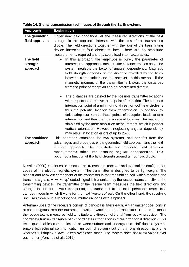
123
Table 14: Signal transmission techniques of through the Earth systems
Approach Explanation
The geometric
field approach
Under near field conditions, all the measured directions of the field
strength in this approach intersect with the axis of the transmitting
dipole. The field directions together with the axis of the transmitting
device intersect in four directions lines. There are no amplitude
measurements required and this could lead into inaccuracies.
The field
strength
approach
In this approach, the amplitude is purely the parameter of
interest. This approach considers the distance relation only. The
system neglects the factor of angular dependency. Magnetic
field strength depends on the distance travelled by the fields
between a transmitter and the receiver. In this method, if the
magnetic moment of the transmitter is known, the distances
from the point of reception can be determined directly.
The distances are defined by the possible transmitter locations
with respect to or relative to the point of reception. The common
intersection point of a minimum of three non-collinear circles is
thus the potential location from transmission. In addition, by
calculating four non-collinear points of reception leads to one
intersection and thus the true source of location. The method is
simplified by the mere amplitude measurement, which is perfect
vertical orientation. However, neglecting angular dependency
may result in location errors of up to 26%.
The combined
approach
This approach combines the two systems, and benefits from the
advantages and properties of the geometric field approach and the field
strength approach. The amplitude and magnetic field direction
measurements takes into account angular dependencies. This
becomes a function of the field strength around a magnetic dipole.
Nessler (2000) continues to discuss the transmitter, receiver and transmitter configuration
codes of the electromagnetic system. The transmitter is designed to be lightweight. The
biggest and heaviest component of the transmitter is the transmitting coil, which receives and
transmits signals. A “wake up” coded signal is transmitted by the rescue teams to activate the
transmitting device. The transmitter of the rescue team measures the field directions and
strength in one point. After that period, the transmitter of the mine personnel resets in a
standby mode in which it waits for the next “wake up” call. On the other hand, the receiving
unit uses three mutually orthogonal multi-turn loops with amplifiers.
Antenna cubes of the receivers consist of band-pass filters each. A transmitter code, consist
of coded signals from the transmitters which awakes another transmitter. The transmitter of
the rescue teams measures field amplitude and direction of signal from receiving position. The
coordinate transmitter sends back coordinates information in three orthogonal directions. This
technique enables communication between surface and underground. Half-duplex systems
enable bidirectional communication (in both directions) but only in one direction at a time
whereas full-duplex allows voices over each other. The system does not allow voices over
each other (Yenchek et al., 2012).

124
The ability to enable full-duplex communication is characterised by the data capacity and
speed of transmission. Half-duplex, only one person can be able to talk at a time and full-
duplex, two persons can talk simultaneously. Transmission rates as high as 2,5 kb/s permit
real-time digitized voice; rates as slow as 10 b/s only allow text messaging at one keystroke
per second (Yenchek et al., 2012). While real-time voice is preferred, through the Earth
transmission is affected by a number of factors due to the complexity of underground
environments.
Data transmission may be limited at very low frequencies. The lowest practical transmission
rates are capable of enabling the greatest penetration depth (Yenchek et al., 2012). At the
same time, the transmission range is influenced by the transmission power (Yenchek et al.,
2012). However, higher transmission power becomes unsafe for the use of electrical
components in methane prone environments.
Larger loop antennas with lower transmission power were used to overcome the safety
challenges. Other than the size of the loop antennas, signal transmission is optimised by
optimizing coupling between the surface and underground installed antennas. The surface
and underground antennas are placed in the same direction; the surface antenna is placed
over the underground antenna to obtain good coupling as shown in Figure 47. The sizes and
orientations of the underground and surface loop antennas have a major influence on the
signal transmission through the Earth.
Figure 47: Aligning loop antennas to obtain good coupling between surface and underground transceivers (Yenchek et al., 2012)
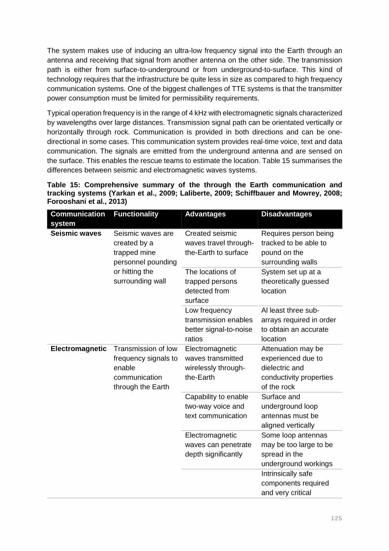
125
The system makes use of inducing an ultra-low frequency signal into the Earth through an
antenna and receiving that signal from another antenna on the other side. The transmission
path is either from surface-to-underground or from underground-to-surface. This kind of
technology requires that the infrastructure be quite less in size as compared to high frequency
communication systems. One of the biggest challenges of TTE systems is that the transmitter
power consumption must be limited for permissibility requirements.
Typical operation frequency is in the range of 4 kHz with electromagnetic signals characterized
by wavelengths over large distances. Transmission signal path can be orientated vertically or
horizontally through rock. Communication is provided in both directions and can be one-
directional in some cases. This communication system provides real-time voice, text and data
communication. The signals are emitted from the underground antenna and are sensed on
the surface. This enables the rescue teams to estimate the location. Table 15 summarises the
differences between seismic and electromagnetic waves systems.
Table 15: Comprehensive summary of the through the Earth communication and tracking systems (Yarkan et al., 2009; Laliberte, 2009; Schiffbauer and Mowrey, 2008; Forooshani et al., 2013)
Communication
system
Functionality Advantages Disadvantages
Seismic waves Seismic waves are
created by a
trapped mine
personnel pounding
or hitting the
surrounding wall
Created seismic
waves travel through-
the-Earth to surface
Requires person being
tracked to be able to
pound on the
surrounding walls
The locations of
trapped persons
detected from
surface
System set up at a
theoretically guessed
location
Low frequency
transmission enables
better signal-to-noise
ratios
Al least three sub-
arrays required in order
to obtain an accurate
location
Electromagnetic Transmission of low
frequency signals to
enable
communication
through the Earth
Electromagnetic
waves transmitted
wirelessly through-
the-Earth
Attenuation may be
experienced due to
dielectric and
conductivity properties
of the rock
Capability to enable
two-way voice and
text communication
Surface and
underground loop
antennas must be
aligned vertically
Electromagnetic
waves can penetrate
depth significantly
Some loop antennas
may be too large to be
spread in the
underground workings
Intrinsically safe
components required
and very critical

126
CSIR: TRAPPED MINER DETECTION AND LOCATION SYSTEM
The system comprises of loop antennas incorporated on a search device and a transponder.
A tag carried by the mine personnel provides at least 30m location range through rock. The
tags are battery powered and can last up to 3 years. The transmitter of the tags emits signals
only when interrogated by the search transmitter. The system consists of a short audio and
visual signal that alerts the trapped person that a rescue operation has been initiated. Also, to
alert that their location has been detected. An inbuilt LED light and a buzzer informs the
trapped persons that their location have been detected. The system allows the trapped person
to send a signal back and this allows the rescue team to confirm that the trapped person is
still alive or conscious.
The tag is inbuilt into the safety belt of the mine personnel. The tag goes to sleep for 29
seconds and wakes up for a couple of milliseconds. When awake, the tag searches for signals
from a transmitter. If no signals detected, the tag goes to sleep for another 29 seconds and
wake up again. If a signal with a valid code has been received, the tag responds by sending
back a coded signal to the transmitter. The transmitter then interrogates the tag for
identification.
The search unit is brought to the scene of accident or area where the trapped persons are
presumed to be by the rescue teams. The search unit continuously transmit signals in search
of a response from tags. Any tag that is within range of the search unit responds by sending
back a signal. When a tag has been detected, the search unit reports it but continues searching
for more tags. The exact location of the trapped person is determined by either ranging from
different angles or by rate of change of signal strength along the line of the trapped person.
The system has an operational distance coverage range of about 40m from the search unit.
In addition, the good thing with this system is that the trapped person can actually
communicate with the rescue team.
TRAPPED MINER LOCATOR: BOOYCO ELECTRONICS
The Selectronic Trapped Miner Locator system was introduced around the same time as the
CSIR Miningtek system. This system was compared with the CSIR Miningtek system, but it
did not meet the requirements of at least 30m through rock of the South African mining
industry. The system was designed and developed specifically for coal mines and this was the
main reason it was declined in the South African deep level mines. The system had a similar
operation with the CSIR Miningtek system.
The Selectronics Trapped Miner Locator system had 20m operational distance as compared
to the 30m of the CSIR Miningtek system. However, the Trapped Miner Locator system (Figure
48) has recently been upgraded to an increased range of up to 30m through rock. According
to the Booyco Electronics (2017), the Trapped Miner Locator system was specifically
developed in response to the South African mining conditions. The rescue teams carry a
locator unit that searches signals from a very low frequency tag mounted on the cap lamps of
the mine personnel. This was mainly due to that very low frequency signals offer pronounced
through-rock capabilities.

127
Figure 48: Trapped Miner Locator system (Booyco Electronics, 2017)
During an underground emergency where mine personnel become trapped, the very low
frequency locator unit together with an antenna are deployed with a rescue team. The locator
device transmits signals which are acknowledged by the tags mounted in the cap lamps of the
mine personnel. The system is capable of detecting trapped mine personnel and allows the
rescue teams to reach the trapped persons quicker than normal searching processes.
The Trapped Miner Locator system allows the tags to be on a permanent sleep mode until
activated by the locator unit. This ensures that tags conserve battery for longer periods such
that even if the person is trapped for a longer period the tag remains operational. Booyco
Electronics (2017) provides products such as proximity detection and collision avoidance
systems.
PJ TECH: CAP LAMP WITH POSITION TRANSMITTER
PJ Tech is a South African based company that was established in 1994. The company offers
cap lamps equipped with position transmitters. The cap lamps assigned to mine personnel are
equipped with a position transmitter unit for rescue purposes in case of emergencies as a
result of accidents. Missing persons, trapped behind collapsed ground can be located using a
Position Finding Receiver carried by a rescue team. The Position Finding Receiver can detect
Position Transmitters through a 30m wall of rock. The Position Finding Receiver carried by
the rescue team detects the distance and direction of trapped and lost mine personnel.

128
THROUGH-THE-EARTH CANARY 2 VITAL ALERT
Vital Alert (2017) is a wireless and through the Earth communication technologies specialist
company based in Canada. The company provides through the Earth, two-way
communication, both vertically (Figure 49) and horizontally (Figure 51). The CanaryComm and
CanaryComm-IS system (Figure 50) are developed specifically for the mining industry
underground environments. The CanaryComm system was specifically designed for situations
where text messaging, voice and data communication over significant depth is required. The
system is used for environments where TTA and through the wire systems have failed or
become ineffective.
Figure 49: Surface transceivers and loop antennas transmitting signals through the Earth from surface (Vital Alert, 2017)
The CanaryComm is used in situations where depth is priority over portability while the
CanaryComm-IS is an intrinsically safe system for mines with possibilities of explosive dust
and flammable gases such as methane. The system provides real-time, two-way voice and
text data for establishing two-way communication and tracking of trapped mine personnel.
Voice and text data is transmitted through solid rock up to 300m using low frequency digital
magnetic induction.
The system was tested successfully to penetrate 122m of rock strata. The CanaryComm
system creates waves that are used to carry proprietary, digitally modulated and magnetic
signals through the Earth rock strata. Wireless, through the Earth text messaging and voice
communication services are provided between surface unit and underground radio handsets.
The rescue team communicates with the missing person underground carrying radio
handsets. The CanaryComm system is integrate-able with existing infrastructure and systems,
but can also function independently. The system consists of additional features including gas
and temperature detection using sensors. The system is likely to become the best solution in
cases where Wi-Fi, RFID and primary networks have failed.

129
The systems utilise a digitally modulated magnetic induction unit to transmit signals as shown
in Figure 50. The system operates in the very low frequency bandwidth ranging between 1
and 9 kHz. The system is battery powered, lasting over 8 hours of continuous transmission
and are rechargeable. The system was designed to withstand the harsh conditions of mining.
It remains operational between -35 to 45 degrees Celsius, and for 0 to 95% humidity.
Figure 50: Electromagnetic waves propagating between surface and underground through the Earth overburden (Vital Alert, 2017)
The CanaryComm weighs 14 kg and the CanaryComm-IS weighs about 64 kg. This makes
the CanaryComm unit to be portable and the CanaryComm-IS to be a station fixed system.
The mine personnel are able to advance with the CanaryComm unit to the new development
areas. However, in the case of an emergency, the surviving mine personnel must manage to
reach to the CanaryComm-IS station in order to communicate their location to the surface
rescue teams.
Figure 51: Electromagnetic waves propagating across haulages - horizontally (Vital Alert, 2017)

130
THE GLON-GLOP SYSTEM
Burnos et al (2010) discusses the GLON-GLOP system used in Polish mines to locate trapped
mine personnel and how the system was improved from the first version. The system was
developed based on the fact that on-ground location systems cannot be used in Polish mines
due to the depth of the mining operations. The other reason was to avoid the dangers of
methane gas which could be ignited by electric devices. The system is comprised of a
transmitter (GLON) carried by mine personnel and a receiver (GLOP) used by the rescue
team. The transmitter operated in the frequency range of 4 000 to 6 000 Hz divided into eight
channels.
The strength of signals received is used to determine the distance between the rescue team
and the missing person. The system is capable of reaching up to 25m and consist of a
direction-finding function. It was reported that the system was not working to satisfactory levels
as it resulted to errors of up to 13% before and was found to be failing to pick signals at shorter
distances. This resulted in the redesign of the GLOP2 system that rectified the shortcomings
of the previous receiver. The GLOP2 receiver is equipped with a LCD display unit. The GLOP2
receiver enabled the locations of signals from a distance of up to 15m with an error less than
1m.
MAGNELINK MAGNETIC COMMUNICATION SYSTEM (MCS)
Martin Lockheed was requested by the National Institute of Occupational Safety and Health
(NIOSH) to develop and demonstrate a two-way, through the Earth communication system for
underground mining operations (Yenchek, no date). The MCS shown in Figure 52 was then
developed and tested by Lockheed Martin. The system was developed to be independent of
either surface or underground infrastructure.
The system comprised of a surface and underground transceiver and loop antenna units.
These units enable mine personnel trapped underground to communicate with rescue
personnel on surface wirelessly through the Earth. The operation of the system requires
placing of the surface station in a location that is in proximity with the underground station.
This is to enable the two stations to establish a communication link with each other. The
trapped persons and rescue teams on surface can be able to exchange voice and text
communication.
Figure 52: Underground transceiver units of the through the Earth MagneLink Magnetic Communication System (Lockheed Martin, 2017)

131
The system was designed with a focus on emergency situations where trapped mine workers
have no other means of communicating to people on surface. The underground station units
are portable and can be placed to an area close to where people are working. The
underground units are added or repositioned as the mine advances and expand in size.
Lockheed Martin was looking to further improve the communication range, remote activation
and monitoring functions of the system.
Figure 53 shows how the system was demonstrated and tested at the Contrary Portal of
CONSOL Energy’s Buchanan mine. This system was actually tested in various sites by
NIOSH. Results from tests proved that the system was successful in establishing two-way
voice communication and two-way text communication to over 470m underground depth. The
system met the intrinsic safety approval requirements of NIOSH.
Figure 53: Rescue teams attempting to communicate with persons trapped inside the mine from surface and from tunnels (Lockheed Martin, 2017)
THE PERSONAL EMERGENCY DEVICE (PED)
The PDE is a through the Earth communication device that works on ultra-low frequency
bands. The system uses its ultra-low frequency transmission capabilities to propagate text
messages through solid rock. The messages can be sent to mine personnel regardless of their
locations underground. The receiving unit (PED) is integrated into the cap lamp battery for
power source and operates at 400 Hz.
The main function of the system is not only to alert mine personnel of emergencies, but also
to provide evacuation instructions to the mine personnel. The system is often referred to as a
primary evacuation warning system. Although the PED system is not necessarily a tracking
system, the system allows communication from surface to the missing person underground.
However, one of the drawbacks of the system is the unidirectional issue. The system requires
installation of antennas both on surface and underground, though the underground antennas
could be damaged during an accident.

132
THE TELEMAG SYSTEM DEVELOPED
The TeleMag system provides through the Earth clear two-way voice, text and data
communication. The system operates between frequencies of 3,000 and 8,000 Hz to
propagate voice and data signals for up to 100m between surface to underground. The system
has been tested at 90m with design calculations indicating up to 300m depths reachable
(Burnos et al., 2010) and the system has been tested at 100m, with up to 330m depth possible
(Bandyopadhyay et al., 2010).
The system requires and underground station and a surface station. The surface and
underground stations are fixed which makes them not portable. The system uses a DSP-
based tracking in combination with a filter for attenuation harmonic-induced noises. The
purpose of the filter is to improve the signal-to-noise ratio during communication. This will
alternatively improve the reach distance of the system (Bandyopadhyay et al., 2010).
The TeleMag through the Earth, two-way voice communication system was first presented by
Barkand et al (2006). Barkand et al (2006) went on to conduct field tests at various types of
mines. The TeleMag system consist of two transceiver units and impedance vertically coupled
loop antennas. The transceiver units are equipped with two individual loop antennas. The one
loop is used for receiving signals and the other for transmitting signals. Transmission in the
system is half-duplex, which means it allows communication in both directions.
Communication is both from surface-to-underground and from underground-to-surface.
However, communication can only happen one at the time and not simultaneously.
Communication between the transceivers is established through magnetic coupling of low
frequency energies between the underground and surface transceivers. The low frequency
radio technology allows the TTE system to work even if the rock is wet (Pronenko and Dudkin,
2016). Figure 54 shows a transceiver and loop antenna located on surface, and the other
transceiver unit and loop antenna located underground. The surface loop antenna must be
positioned directly above the underground loop antenna. The system does not possess signal-
locating capabilities. The base station transceivers are comprised of a cord connected
handsets, push-to-talk intercoms, or mobile hand-held radios. These transceivers utilise single
band modulators to enable the propagation of voice-carrying signals.

133
Figure 54: Through the Earth communication system with surface and underground transceivers and loop antennas (Barkand et al., 2006)
The TeleMag system was tested at the NIOSH Lake Lynn experimental facility and at the
CONSOL, McElroy coal mine, both in the United States of America. At the Lake Lynn facility,
with an overburden thickness of about 83m, an underground transceiver and an 18m diameter
loop antenna were set up. The underground transceiver and loop antenna were placed directly
below the surface transceiver and 18m diameter loop antenna. The system was able to
provide an exchange of a series of voice transmissions both from underground to surface as
well as from surface to underground.
Communication was established using the transceivers and handheld radios. The tests were
successful, enabling real-time, two-way, quality voice communication. The handheld radios
could still enable voice transmission some distance farther from the TeleMag base station.
The McElroy coal mine tests were conducted at an active mine with a depth of 83m from
surface. The same set up, transceivers and 18m loop antennas aligned between underground
and surface, successfully established clear two-way voice communication. The underground
transceiver and loop antenna were moved off the alignment axis by approximately 50m. This
configuration enabled voice transmission from surface to underground, but the surface station
was unable to receive any underground transmission.
The tests were further carried on to a 180m thick overburden but using a 35m diameter loop
antenna to test for communication at greater depths. During this test, both the underground
and the surface units were unable to receive any communication signals. As such, this was
believed to be due to that the underground loop antenna could not be expanded into a perfect
circle because of space constraints underground. However, the system is planned for
extended through the Earth communication for a theoretic limit of 600m below ground.

134
THE TELEMAGNETIC SIGNALLING SYSTEM
NIOSH developed the TeleMagnetic Signalling System in 1997 for emergencies in
underground mines (Conti and Yemen, 1997). The system was developed on ultra-low
frequency, electromagnetic technology to provide communication between surface and
underground during emergencies. The system can transmit and receive warning signals to the
underground personnel. The system transmits emergency warning signals that rapidly reach
to the underground mine personnel. The system is comprised of a low frequency transmitter
that is strategically placed and installed to create electromagnetic signals without the need for
repeaters. However, in some mines, repeaters may be required to ensure and sufficient
network coverage.
The system comprises of a loop antenna located on surface and a receiver loop antenna
placed underground as can be seen Figure 55. The transmitted warning signals causes the
cap lamps and strobe lights to flash and alert mine personnel of an emergency. The system
was developed to be integrate-able with existing fire detection and warning systems. Upon
receiving an emergency or paging signal, the cap lamps begin to flash. The flashing alerts
mine personnel to evacuate or immediately call surface control room depending on the type
of signal received. This system also works for mobile vehicles in underground mines.
Figure 55: The TeleMagnetic signalling system (Conti and Yemen, 1997)

135
2.5.4. SIGNIFICANCE OF AVAILABLE INFORMATION (2.5.1- 2.5.3)
TTE communications systems make use of either seismic wave or electromagnetic wave
signals. The signals are propagated through solid and collapsed rock. The seismic wave and
electromagnetic wave systems use a similar concept of magnetic induction to transmit signals
between surface and underground. These systems do not require any significant infrastructure
to operate, as with the TTW and TTA systems. Nonetheless, these systems have the capability
to locate missing persons. Table 16 summarises the different types of TTE systems that can
potentially be used to locate missing persons. This information will be used in the results
section in Chapter 4. These systems have been found to be less dependent on backbone
infrastructure to operate.

136
Table 16: A summary of commercially available TTE communication systems
TTE Seismic Waves Systems
SureWave Technology The system makes use of micro-seismic waves to establish
communication. The micro-seismic signals enable the system to
reach great depths. The system has currently been tested
successfully at 240 and 320m below ground.
University of Utah The system requires a strategic deployment and placement of
geophones on surface. The geophones must not only be placed
strategically, but as close as possible to the locations of the
trapped persons. The system has been tested, but the depth of
penetration is unknown.
TTE Electromagnetic Waves Systems
CSIR Trapped Miner
Detection and Location
The system can detect the locations of persons trapped behind
rock fall and persons buried in collapsed ground. The system
determines the exact locations of trapped persons in terms of
distance and direction. The system can detect persons trapped
up to 40m through solid or collapsed rock.
Booyco Electronics
Trapped Miner Locator
The system locates persons trapped in solid or collapsed ground.
The system makes use of low frequency signals that can
penetrate through rock. The system has recently been improved
to reach up to 30m through rock. The unique feature of this
system is that the tags are put on a permanent sleep mode in
order to increase the life span of its battery.
Faser: GLON-GLOP The system is capable of detecting persons trapped from a fall of
ground accident. The trapped persons can be detected up to 25m
through rock. The also consists of a direction-finding feature.
PJ Tech: Position
Finding Receiver and
Position Transmitter
The system consists position transmitter unit (tag) and a position
finding unit (signal scanner) to locate persons trapped behind
collapsed ground. The system can penetrate up to 30m through
rock. The tags are integrated into the cap lamp battery.
Vital Alert: Canary 2 The system provides wireless through the Earth text messaging,
voice and data communication. The system has been designed
to penetrate up to 300m of solid rock, but has currently been
tested to 122m. The system is integrate-able with existing
systems with additional features such as gas monitoring.
Lockheed Martin:
MagneLink
The system provides two-way voice and text communication,
wireless through the Earth. The system has been tested to a
depth of 470m.
MST: Personal
Emergency Device
The system provides a warning function during emergencies. The
system enables a one-way text communication function to warn
mine personnel to evacuate. The system also provides
evacuation instructions to the affected workers.

137
Transnek: TeleMag The system is capable of propagating voice, text and data
communication up to 100m between surface and underground.
Communication is established in two-way direction configuration.
While the system is currently tested at 100m, it was designed for
up to 330m.
NIOSH: TeleMagnetic
Signalling System
The system provides warning functions to alert workers to
evacuate. The system is capable of transmitting data signals that
cause the cap lamps of the workers to flash. The cap lamps can
flash in different colours indicating different warnings.

138
2.6. SIGNAL PROPAGATION
TTW systems allow signals to be transmitted along the length of the cable. The wire-based
communication systems often fail after the occurrence of accidents as the cables are
susceptible to damaged. This opened an opportunity for wireless communication and tracking
systems that have a slight chance of surviving accidents. Wireless communication and
tracking systems struggled with clear path or open air for signal transmission. Sun et al (2005)
discusses some of the signal processing techniques.
2.6.1. FACTORS AFFECTING SIGNAL PROPAGATION
The main challenge with wireless systems is associated with signal propagation to establish
communication between readers and tags. Signals are propagated through hardwires using
longitudinal conductors along a tunnel. This system experiences are accessible throughout
the cross-section of the tunnel at the expense of power loss, which is due to an increased
power consumption by the tunnel walls. This kind of loss is reduced by using a two-wire
transmission line system.
Wojtas and Wiszniowski (2012) note that the GPS and GNSS systems are limited to open
space environments where the reference signals from the space satellites are still available.
Wireless technology solutions have the potential for accurate and reliable positioning in
confined spaces such as underground mines. The biggest challenge in underground mines is
associated with the propagation of RF signals to the stopes where miners usually spend a
majority of their time working and travelling. The propagation of signals in underground mining
environments is limited by line-of-sight, and this is also true for HF bands.
Underground mines differ significantly in terms of geological settings and multilevel network
of roadways and tunnels and this may have an influence on the propagation of signals (Wojtas
and Wisziniowski, 2012). Wireless technologies that are operating in microwave bands are
not only affected by line-of-sight and attenuation, but also multipath fading. Underground
mining areas are characterized by strong multipath propagation impact due to the presence
of highly reflective metal structures such as pipe columns, large equipment and machines,
roof bolts and rails.
2.6.2. NETWORK COVERAGE UNDERGROUND
Ranjan and Sahu (2014) realised the need for a tracking and communications system that has
the capability to cover the entire mine. However, the challenge faced is the unsuitable
conditions of mining for tracking and communication systems such as poor line-of-sight,
humidity and excessive dust. These factors have a significant influence on the propagation of
signals as the current data rates and read range can be affected. The relationships between
frequency, propagation or transmission distance and noise levels are always taken into
consideration when measuring the propagation and penetration through rock capabilities of
radio signals.

139
The criteria used in many communication systems are based on increased read range,
efficient use of the frequency bandwidth and the very low power consumption (Yarkan et al.,
2009). The presence of conductors such as metallic structures significantly increases the
coverage of radio signals (Yarkan et al., 2009). This resulted in some researchers investigating
the potential of improving coverage range by using metallic materials in conjunction with
antennas as shown in Figure 56 (Coal Age, 2016). Results showed that coverage range might
be enhanced at MF bands. This can happen in the presence of conductors when radio signals
are coupled and carried over conductors (Yarkan et al., 2009).
Figure 56: Signal propagation testing based on antenna orientation and location within a coal mine entry (Coal Age, 2016)
The types of commodity mined was one of the factors considered in RF signals propagation
characteristics. LF, MF and HF bands for radio waves propagation have been investigated
(Yarkan et al., 2009; Forooshani et al., 2013). The need for high data transmission through
HF communication was focused on increasing data rates and read range. Increasing data rate
using antenna arrays was considered for UHF band communication.
2.6.3. SIGNAL TRANSMISSION MECHANISM
The transmission of signals carrying data between surface and underground, either from
surface to underground or from underground to surface. The generation of large noises from
underground mining activities affects the propagation of radio waves. This is true for TTW,
TTA and TTE communication systems. The optimal frequency range of an RFID
communication system is determined by quantifying the electromagnetic noises that are
created from the underground environments (Mishra et al., 2014).
Attenuation is higher around corners or curves due to the diffraction and scattering of signals
by the roughness of surrounding walls, but relatively low in straight haulages with good line-
of-sight (Mishra et al., 2014). HF technologies usually suffer more from attenuation than low
frequency technologies. Low frequency technologies are capable of working through the rock
and soil. Signal loss increases as frequency increases when propagation is through rock,
metallic objects and obstacles. LF technologies are known to exhibit better signal-to-noise
ratios than HF technologies.

140
Forooshani et al (2013) conducted a comprehensive study and survey on wireless
communication, as well as signal propagation models for underground mining environments.
The study describes how signal transmission undergoes pathloss and fading from the point of
transmission until it reaches the receiver. The signals experience various transmission
phenomena as shown in Figure 57, which include reflection, diffraction, scattering and
refraction. The signals replicate during interactions with the surroundings and the replicas take
multiple paths. The replicas take various paths and directions from the transmitter to the
receiver.
The replicas of the signals reach the receivers after different and encountered delays (time
dispersion quantified by delay spread) and arrive at the receiver from different directions
(angular dispersion quantified by angular spread). If the replicated signals or one of the
transmitters is shifted, rapid changes in the phase relationship between multipath components
can cause the signals to fade (Forooshani et al., 2013). The fading of signals happens on a
small-scale which is characterised by rapid fluctuations of the received signal strength over
distances of propagation, and large-scale which is characterised by signals fading over a large
area. Forooshani et al (2013) also notes that there is a relationship between pathloss and the
distance between the transmitting and receiving device.
Figure 57: Wireless propagation phenomena in a typical underground mining environment (Forooshani et al., 2013)
Electromagnetic wave propagation is a function of frequency range. Electromagnetic fields of
RFID systems are potential sources of ignition in explosive atmospheres (Mishra et al., 2014).
The RFID systems must thus be tested to determine whether they are intrinsically safe,
especially for applications in underground mining environments. Active and passive tags of
the system must also be tested for intrinsic safety due to the on-board power of the batteries.
System with no energy or power storage must also be tested as they can draw enough energy
at very close proximity to the reader to cause ignitions. Figure 58 shows a typical profile of
breakpoints in which signals lose their strengths over a certain distance of propagation.

141
Figure 58: A pathloss model with three signal breakpoints
(Forooshani et al., 2013)
Most of the pathloss models comprise of one or more breakpoints as shown in Figure 58.
These breakpoints differentiate areas where RF waves experience diverse pathloss
exponents (Forooshani et al., 2013). The breakpoints location in a mine tunnel are dependent
on the largest cross-sectional area of the tunnel relative to the signal wavelength. Attenuation
is another factor affecting signal propagation. An attenuation constant is used in modelling the
propagation of electromagnetic waves. The attenuation constant, for example, will be equal to
zero in a vacuum because it is a lossless medium.
The geometry of underground mine tunnels (haulages) has a huge impact on the propagation
of signals. Previous signal propagation models regarded mine tunnels as smooth walls
(Forooshani et al., 2013). The tunnels are considered as wave-guides for radiate signals.
Recently, propagation loss and delay modelling has been done with precision with the use of
new, modified and enhanced software versions. The following parameters are used in the
models:
The mine tunnels act as waveguides for the electromagnetic waves. Overall signals
loss in tunnels consist of roughness loss, antenna insertion loss or equivalently
antenna coupling loss. This occurs due to inefficient coupling of dipole antennas to the
waveguide and reduces rapidly with an increase in wavelength. The tunnel waveguide
parameter takes into account the width, height, surface of sidewalls, footwall and
hangingwall, roughness, distance, tilt angle of sidewalls and the traversal positions of
the antennas.
Pathloss due to noise increases linearly with increasing distance of the tunnel. The
waveguide parameter may overestimate coverage distance if breakpoints of tunnels
are not considered. Pathloss comprises of two different sections that are separated by
the breakpoint. The pathloss parameter is influenced by the free-space region in close
proximity to the transmitter and waveguide in the region further from the transmitting
device.
142
Ray-optical modelling methods are based on reflections but not refractions. The
model assumes two perfectly reflecting sidewalls. The wall roughness was a big factor
in this model.
A full-wave model was then considered. The full-wave model was believed to be
accurate because it fully accounts for the effects of reflection, refraction and diffraction.
The full-wave model enables the provision of a complete solution for the signal
coverage information in a defined space.
Stochastic and numerical models have been recently developed for underground
mines. These models aid to improve the accuracy by focusing on the details of the
surroundings such as the roughness of the side walls. This model sees the roughness
of the wall as a critical parameter for signal propagation.
Various types of systems and technologies that possess tracking and communication potential
and capabilities are available in the market for surface or open environments, while these
systems and technologies face challenges for underground mining applications due to the
harsh conditions of mining. While there is wide variety of communication and tracking systems,
each system operating independently faces unique and complex challenges. Ranjan and
Sahu (2014) discuss the following challenges of communication systems in underground
mining. Table 17 describes the factors that affected the transmission of signals in a typical
underground mine.
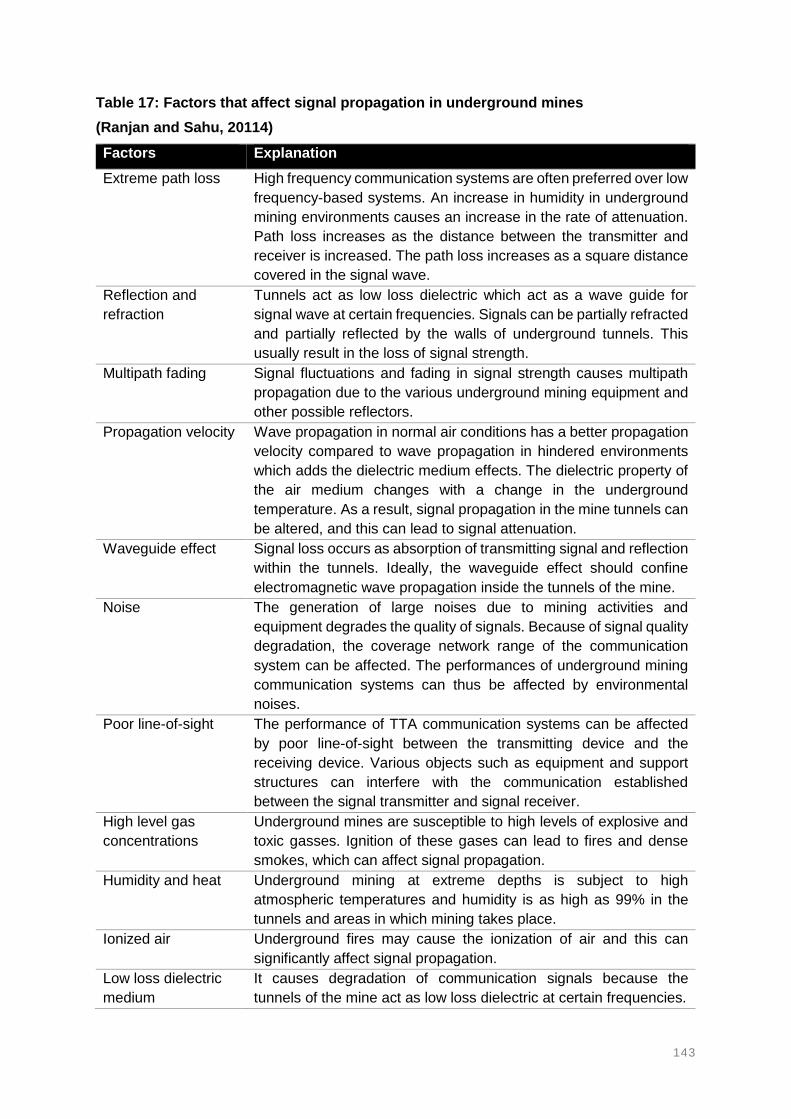
143
Table 17: Factors that affect signal propagation in underground mines
(Ranjan and Sahu, 20114)
Factors Explanation
Extreme path loss High frequency communication systems are often preferred over low
frequency-based systems. An increase in humidity in underground
mining environments causes an increase in the rate of attenuation.
Path loss increases as the distance between the transmitter and
receiver is increased. The path loss increases as a square distance
covered in the signal wave.
Reflection and
refraction
Tunnels act as low loss dielectric which act as a wave guide for
signal wave at certain frequencies. Signals can be partially refracted
and partially reflected by the walls of underground tunnels. This
usually result in the loss of signal strength.
Multipath fading Signal fluctuations and fading in signal strength causes multipath
propagation due to the various underground mining equipment and
other possible reflectors.
Propagation velocity Wave propagation in normal air conditions has a better propagation
velocity compared to wave propagation in hindered environments
which adds the dielectric medium effects. The dielectric property of
the air medium changes with a change in the underground
temperature. As a result, signal propagation in the mine tunnels can
be altered, and this can lead to signal attenuation.
Waveguide effect Signal loss occurs as absorption of transmitting signal and reflection
within the tunnels. Ideally, the waveguide effect should confine
electromagnetic wave propagation inside the tunnels of the mine.
Noise The generation of large noises due to mining activities and
equipment degrades the quality of signals. Because of signal quality
degradation, the coverage network range of the communication
system can be affected. The performances of underground mining
communication systems can thus be affected by environmental
noises.
Poor line-of-sight The performance of TTA communication systems can be affected
by poor line-of-sight between the transmitting device and the
receiving device. Various objects such as equipment and support
structures can interfere with the communication established
between the signal transmitter and signal receiver.
High level gas
concentrations
Underground mines are susceptible to high levels of explosive and
toxic gasses. Ignition of these gases can lead to fires and dense
smokes, which can affect signal propagation.
Humidity and heat Underground mining at extreme depths is subject to high
atmospheric temperatures and humidity is as high as 99% in the
tunnels and areas in which mining takes place.
Ionized air Underground fires may cause the ionization of air and this can
significantly affect signal propagation.
Low loss dielectric
medium
It causes degradation of communication signals because the
tunnels of the mine act as low loss dielectric at certain frequencies.

144
TTE communication systems propagate signals through solid rock and soil. Electromagnetic
waves are transmitted through the Earth strata. The transmission of electromagnetic waves
faces high attenuation problems. Low frequency bands become necessary for penetrating the
Earth strata up to 100m or more in depths. Large antennas, on either side of the strata are
often required to send and receive electromagnetic waves through rock. Magnetic fields in
TTE communications are preferred over electric fields. This is because the Earth does not
only attenuate magnetic fields, but also changes the magnetic field in a lesser amount than it
changes the electric field.
An increase in the size of the antennas is essential for coverage range. However, the power
supply for the underground antennas is restricted. This is solely due to permissibility
requirements of underground mining environments. This is a threat in mines that may contain
explosive gases. Forooshani et al (2013), and Schiffbauer and Brune (2006) state that the
likelihood of successfully establishing communication with the control room on surface using
TTE systems can be influenced by frequency, geology, noise and depth. The conductivity of
the overburden and the presence of any metallic conductors such as steel columns and cables
enhance the transmission through rock.

145
2.6.4. SIGNIFICANCE OF AVAILABLE INFORMATION (2.6.1 – 2.6.3)
Tracking and communication systems are highly dependent on the mechanism of propagating
signals. These signals carry the data that allows the system to operate. The signals are
transmitted either from underground to surface or from surface to underground. The signals
are transmitted through hard-wired cables, through the air or through rock, as the medium of
signal transmission. However, the transmission of signals over the different types of material
can be affected by several factors. Table 18 summarises factors that can affect signal
transmission in each of the three techniques. This information will be carried over to the results
section in Chapter 4.
Table 18: Factors and challenges that limit signal propagation for TTA, TTE and TTW systems
Technique Advantages Disadvantages
TTW Signals enable high data
rates
Less attenuation
incurred
Less noise interference
in the cable
Constant power supply
prevents attenuation
Signals are only transmitted over
the cable and this reduces
network coverage
Connectivity is lost completely if
cable is damaged
Network coverage areas are
limited
Signal transmission is inflexible
TTA Signals enable high data
rates
Increased network
coverage area
Signals transmitted
wirelessly
Wireless system has
less chances of damage
Signal transmission requires
extensive infrastructure
Signal propagation can be
affected by atmospheric
conditions
Requires line of sight to establish
communication link
Requires enough power supply to
transmit signals
TTE Signals are propagated
through rock at no line of
sight
No major infrastructure
required to enable signal
transmission
Low data rates
Distance of signal propagation
through rock is limited
The rock properties can affect the
propagation of signals
Limited network coverage

146
2.7. SYSTEMS AND INFRASTRUCTURE SURVIVABILITY
Communication and tracking systems have been extensively researched to improve the health
and safety of mines globally. Safety played an important role in the development and
introduction of new technology, and tracking and locator systems in underground mines. Some
of the safety systems were developed with additional functions that can also improve the
productivity of mining operations. Various systems and technologies were developed over the
last decades. However, these systems, when operated individually, have not been able to
solve some of the safety challenges in the mining industry according to Yarkan et al (2009).
2.7.1. SURVIVABILITY OF SYSTEMS
The main challenge facing communication and tracking systems for a long time has been the
protection of the systems from damage. Most of the wired and wireless systems are vulnerable
to damage and thus are expected to fail during mining accidents. Wireless communication
systems offered fundamental solutions to the failure of the wired systems (Yarkan et al., 2009).
Once the advantages of wireless systems were realised, many wireless technologies were
developed and implemented in underground mines.
Challenges such as interoperability and seamless connectivity were encountered, and this
necessitated researchers to continuously seek alternative solutions. A system that could work
without wired or wireless infrastructure was seen as the biggest solution to most of the
problems. This resulted in the exploitation of ideas for a system that can work through the
Earth. The TTE electromagnetic systems were actually one the earliest demonstrated systems
by the Bureau of Mines in the United States in 1922 with no success (Yarkan et al., 2009).
TTE communication systems research has been extensively conducted (Yarkan et al., 2009;
Forooshani et al., 2013). Their research highlights the fact that underground mines are
different from each other and therefore will have different problems that cannot be resolved
by a single existing system. The first electromagnetic through the Earth system was developed
in South Africa with little interest at the time (Yarkan et al., 2009). This technique became
critical after noting that regular communication and tracking systems become unavailable due
to impact from accidents, and this left the through the Earth technique as the only option
(Yarkan et al., 2009).
2.7.2. RELIABILITY OF SYSTEMS
Trials and tests were conducted to establish a reliable electromagnetic communication system
between underground and surface (Figure 59). This system operates without line-of-sight
between the two points of interest. One of the first findings was short distance of radio waves
penetration when the frequency was higher. The other challenges were related to the
characteristics of the overburden in which the radio waves are propagated. The failure of
tracking and communication systems in hostile and harsh environments is mainly due to
infrastructure damage and has created the need for a robust communication system that is
capable of withstanding emergencies (Ranjan and Sahu, 2014).

147
Figure 59: Through the Earth system set up for testing at the NIOSH Experimental Mine in Pittsburgh, USA (Reyes of Coal Age News, 2016)
With the exponential evolution of technology over the last decade, the challenges of locating
missing mine personnel after accidents were assessed in various perspectives. The use of
robotics has been recently realised for application in search-and-rescue operations (Yarkan
et al., 2009; Murphy et al., 2008; Yarkan et al., 2008). The use of robots was adopted from
relative industries and has made significant impact in the mining industry.
Robots are capable of transmitting video wireless to surface crew controlling the robots are
now available and applicable in tracking missing persons underground. The robots operating
on the 2.4 GHz frequency band are sent through boreholes to search for trapped mine
personnel in hazardous and confined areas for human access. Not only robots are some of
the relevant devices used, but also thermal imaging cameras, flying drones, heart beat
detectors, breath and sweat sensors have recently been seen working in relevant industries
and accident rescue missions (Murphy, 2004; Casper and Murphy, 2004; Scholtz et al., 2004;
Szajewska, 2017; Huo et al., 2011).

148
2.7.3. SIGNIFICANCE OF AVAILABLE INFORMATION (2.7.1 - 2.7.2)
The importance of communications and tracking systems were highlighted during a number
of mining accidents that trapped or resulted in mine personnel going missing underground for
extended periods of time. Locating mine personnel after accidents evolved from wired systems
when survivors were expected to evacuate and escape to the refuge bays.
The rescue teams on surface could then make phone calls to the phones at the refuge bays
to find out if there are any survivors. However, the wired systems were found to be completely
failing to accomplish the objective of locating underground missing mine personnel, as people
were not able to always escape to the refuge bays. This is because mining accidents would
result in tunnels blockages and hence preventing the mine personnel to evacuate from the
scenes of the accidents. Furthermore, the accidents would also damage the infrastructure and
components of the system. This information will be used in the results section in Chapter 4 for
the development of user requirements.

149
2.8. RELEVANT INDUSTRIES AND DIRECT SEARCH SYSTEMS
This section investigates systems, technologies and devices used in relevant industries for
locating missing persons. This section also investigates devices and related technologies that
have the potential of being adopted in the mining industry for locating missing miners. The
devices investigated in this section are developed in various countries around the world. These
devices were found to be mostly used in natural disaster accident where people became
trapped in rubble material of collapsed buildings or any other disasters (e.g. earthquakes).
2.8.1. ROBOTIC SCOUTING
According to the Human-Centered Robotics Lab (2017) natural and manmade disasters
across various industries and sectors can result in people being injured and trapped in
unknown and inaccessible spaces. The trapped persons will heavily rely on human rescue
teams to save their lives. However, the search-and-rescue operations are usually dangerous
and challenging for humans (Murphy, 2004; Casper and Murphy, 2003; Scholtz et al., 2004).
According to Murphy (2004) the Homeland Security of the USA has been using robots to
respond to disasters where people are trapped in rubble of collapsed buildings.
The first noticeable robotic scouting operation noted was after the World Trade Center disaster
that resulted in people trapped during the collapse of the two twin towers in the USA (Casper
and Murphy, 2003; Murphy, 2004). The disaster resulted in an urgent need for search-and-
rescue operations with sufficient resources. Specialised robotic vehicles were used during the
search-and-rescue operation. These vehicles were operated from a safe distance and used
to access miniature cavities and areas that were in high temperatures and unsafe for rescue
teams to enter (Casper and Murphy, 2003).
The idea of using robotic scouting vehicles gained recognition as a result of the challenges
and difficulties of using humans in hazardous areas. The robots did not only have to locate
survivors, but also recover bodies in the process. The search-and-rescue robotic vehicles
come in various sizes with some small enough to fit into back-packs (Murphy, 2004). The most
valuable robot is that of approximately the size of shoebox (Murphy, 2004). The robots were
quite advantageous and useful in that they could perform tasks that rescue teams were unable
to accomplish such as entering areas that were too small for the rescue teams to enter.
After an accident, some of the areas may be on fire and as such without breathable air. This
makes it difficult for humans (rescue personnel) to enter those areas. Scholtz et al (2004)
strongly suggest that robots need adequate mobility and robustness due to the harsh
conditions encountered during the search-and-rescue operations. Research by Scholtz et al
(2004) shows that a robotic vehicle could cause harm to itself, to the victims or even to the
environment if not used properly. This led to the development of human-robotic interfaces.
Figure 65 shows a robot being used in a search-and-rescue operation.

150
Figure 60: A robotic vehicle leading a rescue team to search for trapped persons in a confined and poor visibility tunnel (Murphy, 2008)
Robotic vehicles have been improved considerably over the last decade. The robots have
been equipped with two-way radio systems, sensors, remote reach-back and other features
necessary in search-and-rescue operations. These features have made robots to be one of
the most reliable ways of searching for survivors in disastrous areas. The robots are used
during the rescue phase to search and examine voids that cannot be examined by humans
(Casper and Murphy, 2003). Murphy (2004) notes that the lack of sensors on the robots
creates limitations on the application of robots. The limitation of sensors is due to the size of
the robots, as it is often lowered in boreholes to access confined areas.
The capabilities of robots to communicate information adequately remains a major issue. This
is due to micro-sized robots that may require a tethered connection. This connection is linked
back to the robot’s power and control source (Murphy, 2004). The tether tangles of the robots
serve as safety lines in cases where the robots are lowered in boreholes. The robots are built
with either wireless or with wired connectivity, which affects the expandability of the robotic
system. Wirelessly connected robots tend to be larger in size, but more mobile than wired
robotic systems. A safety line and communication are still required and can be easily lost in
complicated conditions such as dense smoke and rubble material.

151
A wirelessly connected robotic vehicle was lost during the World Trade Center disaster search-
and-rescue mission due to a lost connection link (Murphy, 2004). This led to researchers
conducting trade-offs between tethered and wireless connectivity for rescue robotic vehicles
(Murphy, 2004; Casper and Murphy, 2003). Ruggedness and ease of operation is one of the
critical requirements. Murphy (2004) further explains that robots cannot act on their own, and
require some level of skills from trained professionals.
Robots depend on the competency of the operators to function effectively and efficiently. Good
human-robot interaction is a critical parameter to the acceptance and success of search-and-
rescue robotic systems (Murphy, 2004). Robot-operator relationship can improve the success
of rescue missions using robots. The study by Murphy (2004) discovered that it takes two
persons from the rescue teams to operate a single robot.
During a search-and-rescue operation, the first person focuses on navigating the robot in the
search area (navigating through vertical drops without tangling the safety rope), while the
second person looks for signs of survivors (problem-holder). Casper and Murphy (2003) see
rescue safety and effectiveness as the two most serious issues of consideration during rescue
missions. This was based on the Mexico City Earthquake that 135 rescue personnel, in which
65 of them were searching in confined and flooded spaces.
Intelligent robotic scouting vehicles can significantly improve the safety and efficiency of
search-and-rescue missions if they are collaborating well with humans. Scholtz et al (2004)
noted that progress made concerning autonomous robots was influential to the success of the
missions. During search-and-rescue missions, robots can also provide medical support.
The robots can provide two-way communication between rescue teams and trapped person,
deliver medication and biosensors to the trapped person. However, Casper and Murphy
(2003) note that the current rescue robot technology was not advanced at the time. The robots
were not advanced enough to operate autonomously and thus required a controller. This is
where the human-robot interaction was noticed as a key component. Robot platforms from
various manufacturers may vary in terms of size, type of mobility and ruggedness (Casper and
Murphy, 2003).
THE GEMINI-SCOUT ROBOT
First response to an accident is often restricted by poor visibility, harmful gases, floods,
unstable roof and walls. Robots can navigate under water, crawl over large rocks and rubble
material, and scans and evaluate the area and plan the search-and-rescue operation. The
robot is equipped with gas and temperature sensors, thermal imaging cameras for locating
persons as well as a viewing camera that can be tilted (see Figure 61). The robot can access
and navigating tight corners where access by persons is restricted. The robot can also be
used for transporting food, air-packs and medicine to the trapped miners.
A two-way radio is also equipped on the robot for establishing communication with located
survivors. The robot was designed to try and overcome obstacles for all possible known
hazards. The robot can withstand methane explosions with its casings used to house it and
have the following capabilities: Waterproof to work in water, Lightweight for flexibility, Xbox
360 game controller used to direct the scouter, and Prevents creating another dangerous
situation with explosions. A typical robotic scouting vehicle with some of the equipped features
is shown in Figure 61.
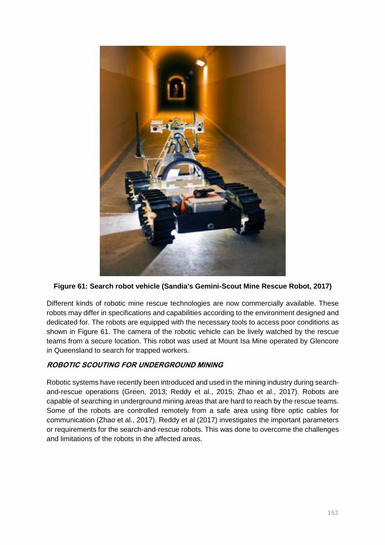
152
Figure 61: Search robot vehicle (Sandia's Gemini-Scout Mine Rescue Robot, 2017)
Different kinds of robotic mine rescue technologies are now commercially available. These
robots may differ in specifications and capabilities according to the environment designed and
dedicated for. The robots are equipped with the necessary tools to access poor conditions as
shown in Figure 61. The camera of the robotic vehicle can be lively watched by the rescue
teams from a secure location. This robot was used at Mount Isa Mine operated by Glencore
in Queensland to search for trapped workers.
ROBOTIC SCOUTING FOR UNDERGROUND MINING
Robotic systems have recently been introduced and used in the mining industry during search-
and-rescue operations (Green, 2013; Reddy et al., 2015; Zhao et al., 2017). Robots are
capable of searching in underground mining areas that are hard to reach by the rescue teams.
Some of the robots are controlled remotely from a safe area using fibre optic cables for
communication (Zhao et al., 2017). Reddy et al (2017) investigates the important parameters
or requirements for the search-and-rescue robots. This was done to overcome the challenges
and limitations of the robots in the affected areas.

153
The robots are built with various functions and features to improve effectiveness during
search-and-rescue operations. The robots are equipped with multiple cameras and lighting
systems to assist during the search-and-rescue operations. The robot has built-in, on-board
drill, grinder and cutter with pressure driven manipulators claws. The robots are often track
mounted to overcome potential obstacles in the tunnels such as water, mud and rocks.
2.8.2. THERMAL IMAGING CAMERAS
Thermal imaging cameras comprise of passive sensors that capture the infrared radiation
emitted by materials with a temperature greater absolute zero (Gade and Moeslund, 2014).
These cameras are widely used by firefighters for rescuing people trapped near fires
(Szajewska, 2017). The cameras have been extensively used in fighting fires in burning
buildings, but another great use has been combating the effects of natural disasters and
catastrophic events. This can include searching for missing persons, evacuating people and
animals in areas affected by darkness, smoke and fog (Szajewska, 2017).
The thermal imaging cameras were originally developed for surveillance and night vision for
military purposes (Gade and Moeslund, 2014). However, the cameras are now extensively
used in various industries for a wide range of applications. The colours and visibility of
substances/objects through thermal cameras is dependent on the source of eenergy. The
images depicted by thermal imaging cameras based on illumination, change in intensity,
colour balance, direction and others. The cameras were developed from the theory of
electromagnetic radiation and electromagnetic spectrum (Cool Cosmos, 2013). When the
body is hotter, it glows more brightly at shorter wavelengths and cooler bodies glow faintly at
longer wavelengths as demonstrated in Figure 62 (Cool Cosmos, 2013).
Figure 62: The electromagnetic spectrum and electromagnetic radiation (Cool Cosmos, 2013)
Infrared light that falls on the body will cause it to warm up (Figure 63). Once the body is warm,
it emits light waves that carry energy. Shorter wavelengths carry more energy than longer
wavelengths (Cool Cosmos, 2013). However, the camera is unable to detect images in total
darkness (Gabe and Moeslund, 2014). The thermal imaging cameras can also form part
robotic scouters and flying drones for search-and-rescue purposes in smoky areas. Figure 63
shows how infrared can be used to detect heated bodies.

154
Figure 63: Radiation of a heated object (Cool Cosmos, 2013)
The cameras used by firefighting teams make use of hand held infrared technology cameras
for searching of missing and trapped persons and animals in fire accidents. These fires could
be in buildings or in the wild. Infrared body heat from humans can pass through dense smoke.
This gives the image of the human on the infrared camera in smoky areas. The cameras detect
the infrared body heat from people through heavy smoke and flames. The infrared technology
is also applicable in locating missing hikers and climbers. Figure 64 demonstrates the use of
thermal imaging cameras. On the left, the rescue personnel are unable to identify the missing
person by eyeing. However, with use the camera on the right, the rescue personnel can detect
the missing person on the floor.
Figure 64: Infrared thermal imaging camera detecting and locating the body of a human being on the floor in a dense smoke area (Cool Cosmos, 2013)

155
2.8.3. UNMANNED AERIAL VEHICLES
Flying drones, also referred to as unmanned aerial vehicles (UAV) are autonomously flying
smaller aeroplanes that can fly in the air. These UAV’s are built with various applications; such
as stockpile survey, 3-D pit modelling, aerial monitoring and scanning (Mitchell and Marshall,
2017; Floreano and Wood, 2015). The use of UAV’s in underground mining includes
applications such as cavity scanning and monitoring areas that are dangerous for humans to
enter. Research has recently been focused on developing small and human-friendly UAV’s
that can autonomously fly in confined spaces and close to people (Floreano and Wood, 2015).
Drones have always been developed to fly in the air, above ground. This gives drones the
advantage of accessing hazardous and confined spaces. The applicability of drones strongly
depends on its capabilities of autonomously and safely manoeuvring under confined and
compromised environments (Floreano and Wood, 2015). According to Mitchell and Marshall
(2017), drones may be more efficient when used on surface compared to underground.
UAV’s have been known to have the potential to assist in search-and-rescue operations,
especially in disastrous situations (Apvrille et al., 2015; Camara, 2014). Naidoo et al (2011)
investigated the use of UAV’s in search-and-rescue applications related to events such as
earthquakes. It was found that the application of UAV’s entails a significant amount of control
to execute search-and-rescue operations. These devices can provide and give rescue teams
a head-start of areas where there are high chances of locating trapped people. Another
advantage of UAV’s is the capability to perform multiple tasks simultaneously. The
effectiveness and efficiency of drones can be significantly influenced by its ease of control.
For an example, Mine Rescue Drones developed by Your Flying Camera Drone (2016)
provide up to the minute real-time, live, high quality (HD) video and aerial footage of the
emergency site or search-and-rescue location. The mine rescue drones stream live video play
back to a command base or rescue team while the drone is still flying. Drones are used
similarly to robotic vehicles to search for trapped miners. Drones were attempted for the
search-and-rescue of the three trapped mine workers at the Lily mine accident on the 15th of
February 2016.
2.8.4. ROBO-WORMS
Jordan Boyle from the University of Leeds (New Scientist, 2011) created a robotic-worm that
can be used for searching people trapped in collapsed buildings. This invention came after a
thorough study of the nematode worm (Caenorhabditis elegans). The robotic-worm was
developed in a software that mimics the unique motion of worms. The nematode worm can
vary its wiggling frequency fourfold that enables a wide range of speeds and undulating
motions. Boyle continues to explain that the worm has an unusual small nervous system
comprising of over 300 neurons.
Rather than using a central neural sub-circuit as a pattern generator, the worm generates its
own undulatory motion. The motion is created by using about 100 neurons in a way largely
driven by feedback from stretch sensors along its body. The study resulted in the creation of
a 2-meter long and 16-centimter wide robot that resembles the motion of the worm. The robot
makes use of sensors that control its motion to mimic the motion of worms.

156
The robot consists of 12 articulated segments that replicate the worm-like motions of the robot.
Each of the 12 segments can swing from side to side using a geared motor in its centre. These
kinds of robots were first used in the construction industry to assess areas that are hard to
reach and access (Emami Design, 2017). The robot uses controlled magnetisation of metal
rings integrated into a silicone tube. Figure 65 demonstrates the configurations of the motion
created by the sensors of the robot.
Figure 65: RoboWorm design concept to replicates worm’s movements (Emami Design, 2017)
Emami Design (2017) of Germany has developed a RoboWorm system as shown in Figure
65. The worm-like robot has a unique motion design that enables it to move on rough and
uneven surfaces. When deployed, the robot senses an angle described by each sensor with
respect to its spine and control software. This information calculates the overall undulation
pattern and orientation of the robot. The robot is equipped with microphones, gas detecting
sensors and infrared cameras on its head. These features enable the robot to search for
people in confined spaces.
Figure 66 shows some of the affected areas that the RoboWorm can access. Various robotic
worm systems exist, but it is yet to be known if they have been used successfully in relevant
applications. One of the robots, called the RoboWorm, designed by Emami Design, has a
movement pattern that mimic the motion of an Earthworm. The shape and size of the
RoboWorm enables it to navigate through tight and spaces that are inaccessible by humans.
The RoboWorm is built with two heads on each end and this enables it to move forward and
backwards without having to flip over.
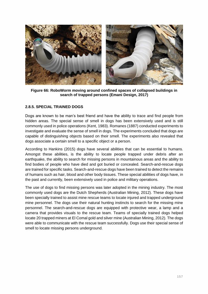
157
Figure 66: RoboWorm moving around confined spaces of collapsed buildings in search of trapped persons (Emani Design, 2017)
2.8.5. SPECIAL TRAINED DOGS
Dogs are known to be man’s best friend and have the ability to trace and find people from
hidden areas. The special sense of smell in dogs has been extensively used and is still
commonly used in police operations (Kent, 1983). Romanes (1887) conducted experiments to
investigate and evaluate the sense of smell in dogs. The experiments concluded that dogs are
capable of distinguishing objects based on their smell. The experiments also revealed that
dogs associate a certain smell to a specific object or a person.
According to Hankins (2015) dogs have several abilities that can be essential to humans.
Amongst these abilities, is the ability to locate people trapped under debris after an
earthquake, the ability to search for missing persons in mountainous areas and the ability to
find bodies of people who have died and got buried or concealed. Search-and-rescue dogs
are trained for specific tasks. Search-and-rescue dogs have been trained to detect the remains
of humans such as hair, blood and other body tissues. These special abilities of dogs have, in
the past and currently, been extensively used in police and military operations.
The use of dogs to find missing persons was later adopted in the mining industry. The most
commonly used dogs are the Dutch Shepherds (Australian Mining, 2012). These dogs have
been specially trained to assist mine rescue teams to locate injured and trapped underground
mine personnel. The dogs use their natural hunting instincts to search for the missing mine
personnel. The search-and-rescue dogs are equipped with protective wear, a lamp and a
camera that provides visuals to the rescue team. Teams of specially trained dogs helped
locate 20 trapped miners at El Comal gold and silver mine (Australian Mining, 2012). The dogs
were able to communicate with the rescue team successfully. Dogs use their special sense of
smell to locate missing persons underground.

158
Dogs are generally smaller in size and are flexible to access confined spaces and caved-in
areas underground. The dogs can be equipped with the necessary equipment to deliver to the
trapped person, while the rescue team is on its way. The dog can communicate the location
of the trapped miner to the rescue team. Dogs are flexible to work in confined, small and
narrow tunnels, and have been previously used in Australian mine rescue operations. The use
of dogs in underground mining search-and-rescue missions was adopted from surface
disasters such as natural disasters and collapsed buildings. About 300 special trained dogs
were used at the search-and-rescue mission at the World Trade Center accident on 11
September 2001 (TODAY, 2013). The dogs helped find people who had survived the accident
but were still trapped in rubble.
2.8.6. HEART-BEAT DETECTING DEVICE
The Heartbeat detector system was developed by the National Administration of Space
Agency (NASA) helps find missing people who are trapped in a collapsed building (Shubber,
2013). The technology was developed based on the limited options of determining whether
people trapped in rubble are still alive or not. The technology has been developed and tested
by NASA to detect the heartbeat of humans buried under collapsed buildings. The device is
named Finding Individuals for Disaster and Emergency Response (Finder).
The FINDER device uses microwave radiation to detect chest movement associated with the
beating of a heart as well as breathing. The system has been tested to detect the heartbeat
of people buried in collapsed buildings by detecting rhythmic waves of the heartbeat. Tests
have shown that the device can detect the presence of a heartbeat through approximately 9m
of crushed material and 6m of solid concrete. The device could detect heartbeat up to 30m in
open spaces.
2.8.7. BREATH AND SWEAT SENSING DEVICE
People trapped due to collapse of ground or buildings begin to release volatile metabolites
through their skin, urine release and change in breath (Huo et al., 2011). The released volatile
metabolites are organic compounds associated with blood and viscera. A project funded by
some European countries (includes United Kingdom, Greece, Romania and Germany in
collaboration) is developing a breath-detecting device to rescue trapped persons. The device
is being developed by Second Generation Locator for Urban Search and Rescue operations
(SGL for USaR).
The device can detect people trapped in voids and rubble of collapsed buildings. The device
makes use of the volatile metabolites compounds released by casualties. The device senses
carbon dioxide and ammonia through the air flow around the area in which the missing people
are being trapped. The device works under the assumption that if air in a void is not
replenished, carbon dioxide levels will increase while the oxygen level drops. Various
experiments and simulations of people trapped in collapsed buildings have been conducted,
and showed that:
CO2 is the first gas detected by the device and travelled rapidly through the collapsed
building debris,
Ammonia, NH3 levels increased rapidly during the experiment, and
Volatile organic compounds such as acetone and isoprene were detected by the
device.

159
The Institute of Physics (2011) has also developed a sensor device that can detect the
presence of humans from their breath, sweat and skin. The sensor device uses the molecules
of breath, sweat and skin to detect the presence of humans in collapsed buildings. The
sensors are portable and usable in real-life situations where flumes of air can be used to create
a profile of molecules that could indicate human presence.
The sensors are built to detect carbon dioxide and ammonia gases with high sensitivity, as
well as a large number of volatile organic compounds such as acetone and isoprene. These
are compounds that were selected from a study that showed that when the human body is
trapped in collapsed buildings begins to secrete and release volatile metabolites. These are
products of the natural breakdown mechanism of the body when under stress or panic. The
process of detecting breath, sweat and skin metabolites can be affected by a change in
humidity, heat, and strength and direction of wind.
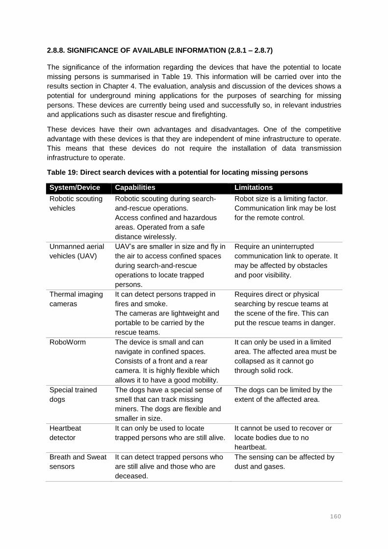
160
2.8.8. SIGNIFICANCE OF AVAILABLE INFORMATION (2.8.1 – 2.8.7)
The significance of the information regarding the devices that have the potential to locate
missing persons is summarised in Table 19. This information will be carried over into the
results section in Chapter 4. The evaluation, analysis and discussion of the devices shows a
potential for underground mining applications for the purposes of searching for missing
persons. These devices are currently being used and successfully so, in relevant industries
and applications such as disaster rescue and firefighting.
These devices have their own advantages and disadvantages. One of the competitive
advantage with these devices is that they are independent of mine infrastructure to operate.
This means that these devices do not require the installation of data transmission
infrastructure to operate.
Table 19: Direct search devices with a potential for locating missing persons
System/Device Capabilities Limitations
Robotic scouting
vehicles
Robotic scouting during search-
and-rescue operations.
Access confined and hazardous
areas. Operated from a safe
distance wirelessly.
Robot size is a limiting factor.
Communication link may be lost
for the remote control.
Unmanned aerial
vehicles (UAV)
UAV’s are smaller in size and fly in
the air to access confined spaces
during search-and-rescue
operations to locate trapped
persons.
Require an uninterrupted
communication link to operate. It
may be affected by obstacles
and poor visibility.
Thermal imaging
cameras
It can detect persons trapped in
fires and smoke.
The cameras are lightweight and
portable to be carried by the
rescue teams.
Requires direct or physical
searching by rescue teams at
the scene of the fire. This can
put the rescue teams in danger.
RoboWorm The device is small and can
navigate in confined spaces.
Consists of a front and a rear
camera. It is highly flexible which
allows it to have a good mobility.
It can only be used in a limited
area. The affected area must be
collapsed as it cannot go
through solid rock.
Special trained
dogs
The dogs have a special sense of
smell that can track missing
miners. The dogs are flexible and
smaller in size.
The dogs can be limited by the
extent of the affected area.
Heartbeat
detector
It can only be used to locate
trapped persons who are still alive.
It cannot be used to recover or
locate bodies due to no
heartbeat.
Breath and Sweat
sensors
It can detect trapped persons who
are still alive and those who are
deceased.
The sensing can be affected by
dust and gases.

161
2.9. EVALUATING THE EFFECTIVENESS OF LOCATOR, TRACKING AND TWO-WAY
COMMUNICATION SYSTEMS
Various types of systems, technologies and devices that have the potential to track, locate
and establish two-way communication with missing persons in underground mining
environments have been identified. These systems have different functionalities, capabilities
and limitations that determine the effectiveness and performances of the systems. This section
discusses parameters that have been considered and used to measure the suitability,
effectiveness and performances of such systems. The effectiveness and system performance
determine how quick a system can track and locate missing persons.
2.9.1. SYSTEM EFFECTIVENESS AND PERFORMANCES
According to Schafrik et al (2013) there was no uniform method at the moment that can be
used to measure the effectiveness, and also to evaluate the performances of tracking and
communication systems. The evaluation of the effectiveness of tracking and communication
systems is essential and required to assess the capabilities and limitations of the commercially
available systems. An evaluation method can be used to assess tracking and two-way
communication systems in order to satisfy regulatory requirements (Schafrik et al., 2013;
Harwood et al., 2011).
Some tracking and communication systems are more applicable in certain types of
underground mining environments than others. Therefore, during the evaluation process,
mining operations can be able to identify their most suitable system. The topologies of
underground mining environments can be complex in nature and thus affecting the operational
capabilities of the tracking and communication systems. The shaft, haulages and mining areas
are of different dimensions and this has an influence on the type of system required.
Harwood et al (2011) note that the evaluation, modelling and field testing of tracking and
communication systems has been lagging. This has been due to urgent need and enforcement
of new mine legislations and regulations. Harwood et al (2011) developed a methodology for
evaluating tracking and communication systems in underground mines. The focus of the study
was on developing tools and protocols that can be used to assess and determine the suitability
of the systems when specifically applied in the mining industry.
2.9.2. SYSTEM EVALUATION PARAMETERS
Several research studies have developed user specifications that can be used to assess and
measure the performances of the systems used in the mining industry and relevant industries
(Schafrik et al., 2013; Harwood et al., 2011; Progri, 2003; Liu et al., 2007; Tekinay et al., 1998).
The user specifications developed by the different authors are summarised in Table 20. These
specifications define the business need for the system.
The need for an assessments and evaluation technique would enable mines and regulators
to predict the performance of the systems installed in their mines (Schafrik et al., 2013). Not
only the currently installed systems should be evaluated and assessed, but the evaluation tool
can also help develop new types of systems and technologies that can be more effective
(Harwood et al., 2011). Amongst other factors, the user specification evaluation methodology
should also take into consideration the geometries of different mines.

162
Table 20: System evaluation metrics for different industries
Industry Cellular
telephone
Indoor, outdoor
and underwater
Indoor Underground
mining
System
Evaluation
Metrics
Accuracy Accuracy Accuracy Accuracy
Data rates Integrity Precision Predictable
Coverage Availability Complexity Repeatable
Capacity Compatibility Robustness Relative
Interoperability Scalability Confidence radius
Continuity Cost Coverage
Communication Latency
Availability and
reliability
Susceptibility
Robustness
Reference Tekinay et al
(1998)
Progri (2003) Liu et al (2007) Harwood et al
(2011)

163
2.9.3. SIGNIFICANCE OF AVAILABLE INFORMATION (2.9.1 - 2.9.2)
System effectiveness and performance refer to the suitability of the system in tracking and
locating missing persons. The higher the effectiveness and performance of the system means
that the system can track and locate missing persons in the shortest possible time. This can
lead to saving lives of missing persons. The factors that determine the effectiveness and
performances of a system will be taken into consideration in developing user requirements for
a fit for purpose system.
System functionalities: Different systems have different functions and can be used
for specific purposes. Various systems, technologies and devices have been
investigated and identified and the functions of these systems determine the
applicability and suitability of each system.
System capabilities: Some systems may have the same functions, but their
capabilities may differ from one manufacturer to another. The capabilities of the system
should be assessed and understood in order to ensure that the correct system is being
selected for specific mine and purpose.
System limitations: The systems performances can be limited or restricted by several
factors and challenges encountered in the mining environments. These limitations
affect the performance of the systems and this may lead to the system being unable
to track and locate missing persons when required.
Type of mine: The selection of a system can also be influenced by the type of mine.
This due to the differences in excavation dimensions and general layout of the different
mines.
System performance measures and system evaluation metrics are essential in understanding
the capabilities and limitations of the different systems. This will allow mine operators to select
and implement the right system that can be the most suitable for their mines. This does not
only take into consideration the design of the systems, but also the environments where the
systems are expected to operate. This information will be carried over and used in the results
section in Chapter 4.

164
2.10. SIGNIFICANCE OF AVAILABLE INFORMATION – CHAPTER 2
The literature review has identified several systems, technologies, devices as well as
techniques that can be used to find (locate or track) missing persons in underground mining
environments. These persons usually go missing after the occurrence of an accident, but may
be lost due to other reasons or causes. Some of the systems, technologies, devices and
techniques have proven to be fit for purpose, while some are still being developed, tested and
trialled. The systems in development stages aim to address the challenges that are facing
some of the currently available and used systems. As a result, these systems should be able
to effectively track and locate missing persons and ultimately save lives.
In the literature review, considerations were given to locator, tracking and two-way
communication systems in mining, as well as direct search devices used in relevant industries
that have the potential to be adopted and applied in the mining industry. The type of
infrastructure required to operate each of the systems was also considered. This included a
broad understanding of the factors and challenges that can affect the functions and capabilities
of the backbone infrastructure as well as the systems. This can enable manufacturers to
modify and improve on their current systems.
The study acknowledges the fact that mining is a very dynamic industry and faces several
challenges that can limit most of the currently available systems. The capabilities and functions
of the identified systems can be heavily affected by the nature of underground mining
environments. It was realised that there is still room for improvement with the existing systems.
Nonetheless, a wide range of systems have been identified and these systems show a great
potential for tracking and locating missing persons. Table 21 summarises the various types of
systems, technologies and devices that have been identified as well as the three main
techniques in which communication is established.
Table 21: Summary of locator, tracking and communication systems applicable in tracking and locating missing persons in underground mines
Signal transmission techniques
Through-the-Wire Technologies
Through-the-Air Technologies
Through-the-Earth Technologies
Relevant industry Systems
Through-the-Wire
Copper wires Passive RFID Seismic waves Robotic scouting vehicles
Through-the-Air
Leaky Feeder Active RFID Electromagnetic waves
Flying drones
Through-the-Earth
Fibre Optics Wireless Fidelity Thermal imaging cameras
Telephones ZigBee Heart beat detectors
Bluetooth Breath and sweat sensors
Near Field Communication
RoboWorms

165
The systems, technologies and devices highlighted in Table 21 have the potential to track,
locate and enable communication with missing persons in underground mines. The systems
have their own capabilities and limitations in terms of their applications. Some of these
systems (TTW and TTA based systems) require a backbone network and power supply
infrastructure, while other (TTE based systems) operate independent of infrastructure. Some
of the systems only work in line-of-sight while other can penetrate significantly through the
Earth.
TTW (Two-way voice communication systems)
o Enable two-way voice and data communication between surface and
underground in real-time.
o Data transmission between surface and underground requires backbone
infrastructure.
o Data transmission infrastructure and the system can be damaged during an
accident and fail.
TTA (Two-way voice and Tagging and tracking systems)
o Enable two-way voice, text, video and data communication between surface
and underground in real-time.
o Data transmission between surface and underground requires installation of
backbone infrastructure.
o Data transmission infrastructure and system are susceptible to damage during
accidents.
TTE (Seismic waves and Electromagnetic waves systems)
o Enable text and data transmission between surface and underground through
the earth’s rock.
o Very less to no infrastructure required for these systems.
o System most likely to survive accidents and remain operational after the
occurrence of the accident.
Some systems have been adopted from relevant industries. The identified systems will be
used to recommend strategy that can be used to effectively and efficiently locate missing
persons. Some of the systems show the potential to be integrated with other systems and in
existing infrastructure. This information will be carried over to the results section in Chapter 4.
This information will be used as part of the process to select and recommend a suitable and
fit for purpose system as a solution to the problem.

166
LIST OF REFERENCES: CHAPTER 2
Akyildiz, I.F., Sun, Z. and Vuran, M.C. (2009). Signal propagation techniques for wireless
underground communication networks. Physical Communication Journal, 2, 167 – 183.
Apvrille, L., Roudier, Y. and Tanzi, T.J. (2015). Autonomous drones for disasters
management: Safety and security verifications. URSI AT-RASC Conference. Available
online: https://ieeexplore.ieee.org/document/7303086
Bandyopadhyay, L.K., Chaulya, S.K. and Mishra, P.K. (2010). Wireless communication in
underground mines: RFID-based sensor networking. Springer Publication, New York, USA.
Bandyopadhyay, L.K., Chaulya, S.K., Mishra, P.K., Choure, A. and Baveja, B.M. (2009).
Wireless information and safety system for mines. Journal of Scientific and Industrial
Research, 68, 107 – 117.
Barkand, T.D., Damiano, N.W. and Shumaker, W.A. (2006). Through-the-Earth, Two-way,
Mine Emergency, voice communication systems. IEEE Industry Application Society, 2, 955 –
958.
Barnard, M.E. (1992). The Global Positioning System. IEE Review, 99 – 102.
Becker Mining Systems. (2017). Tagging and Tracking in Underground Mining. Available at:
http://varismine.com/products
Belyaev, E.N. (2017). Extended investigation into continuous laser scanning of underground
mine workings by means of Landis inertial navigation system. IOP Conference Series: Earth
and Environment Science. Available online: https://iopscience.iop.org/article/10.1088/1755-
1315/87/5/052002
Bluetooth Special Interest Group. (2017). Bluetooth Technology. Available online:
www.bluetooth.com
Boddu, R., Balanagu, P. and Babu, N. (2012). ZigBee based mine safety monitoring system
with GSM. International Journal of Computer and Communication Technology, 3(5), 63 – 67.
Bouet, M. and dos Santos, A.L. (2008). RFID Tags: Positioning principles and localization
techniques. 1st IFIP Wireless Days. Available online:
https://ieeexplore.ieee.org/xpl/mostRecentIssue.jsp?punumber=4808202
Boyco Electronics. (2017). Trapped Miner Locator. Available online: http://www.booyco-
electronics.co.za/product-range/trapped-miner-locator.
Brown, A.K., Sturza, M.A. and NAVSYS Corporation. (1993). Vehicle tracking system
employing Global Positioning System (GPS) Satellites. United States Patent.
Burnos, P., Gajda, J. and Maj, P. (2010). Digital system for detection and location of miners
trapped in hard coalmines – GLOP2. Journal of Metrology and Measurement Systems,
17(2), 245 – 254.
Business Wire. (2013). Minetec Partners with CSIRO to Deliver Revolutionary Underground
Positioning Technology for Trax+Tags™ II to the Mining Industry. Available online:
http://www.businesswire.com/news/home/20130819006343/en/Minetec-Partners-CSIRO-
Deliver-Revolutionary-Underground-Positioning.

167
Camara, D. (2014). Cavalry to the rescue: Drones fleet to help rescuers operations over
disasters scenarios. IEEE Conference on Antenna Measurements & Applications (CAMA).
Available online: https://ieeexplore.ieee.org/xpl/mostRecentIssue.jsp?punumber=6992838
Carreno, J.P., de Silva, L.S., de Almeida Neves, S.O., Aguayo, L., Braga, A.J., Barreto, A.N.
and Garcia, L.G.U. (2016). Through-The-Earth (TTE) communications for underground
mines. Journal of Communications and Information systems, 31(1), 164 – 176.
Casper, J. and Murphy, R.R. (2003). Human – Robot interactions during the robot-assisted
urban search and rescue response at the World Trade Center. IEEE Transactions on
Systems, Man, and Cybernetics – Part B Cybernetics, 33(3), 367 – 385.
Chen, G., Shen, C. and Zhou, L. (2009). Design and performance analysis of wireless
sensor network location node system for underground mine. Journal of Mining Science and
Technology, 19(6), 813 – 818.
Chen, K-M., Huang, Y., Zhang, J. and Norman, A. (2000). Microwave life-detection systems
for searching human subjects under earthquake rubble or behind barrier. IEEE Transactions
on Biomedical Engineering, 27(1), 105 – 114.
Chiu, Y., Yen, D.C. and Shih, D. (2011). Importance – performance analysis for the adoption
of radio frequency identification technology. Journal of Information Technology Management,
xxii (2), 30 – 40.
Cierpisz, T. 2013. Location of people and machines with the use of the PORTASsystem.
Master’s thesis. SYBET.
Coal Age. (2016). Communications and Tracking Research Supports MINER Act. Available
online: https://www.coalage.com/features/communications-and-tracking-research-supports-
miner-act/
Conti, R.S. and Yewen, R.G. (1997). Evaluation of a signalling and warning system for
underground mines. Report of Investigations 9641, National Institute for Occupational Safety
and Health. Available online: https://www.cdc.gov/niosh/mining/works/coversheet1301.html
Cool Cosmos. (2017). Thermal imaging cameras. Available online:
http://coolcosmos.ipac.caltech.edu
CSIRO. (2017). Position location system. Available online: www.csiro.au/dpas or
http://www.csiro.au/en/Outcomes/ICT-and-Services/People-and-businesses/Position-
Location-System.aspx.
Cumming-Potvin, D., Wesseloo, J., Potvin, Y. and Green, M. (2013). Investigating the
potential for locating trapped miners using a pre-existing microseismic monitoring system. 8th
International Symposium on Rockbursts and Seismicity in Mines, 145 – 156.
Cypriani, M., Delisle, G. and Hakem, N. (2013). Wi-Fi-based positioning in underground
mine tunnels. International Conference on Indoor Positioning and Indoor Navigation.
Available online: https://ieeexplore.ieee.org/document/6817894
Damiano, N., Homce, G. and Jacksha, R. (2014). A Review of underground coal mine
emergency communications and tracking system installations. CoalAge. Available online:
http://www.coalage.com/features/4078-a-review-of-underground-coal-mine-emergency-
communications-and-tracking-system-installations.html#.WlxlJ6iWaM8
http://www.csiro.au/en/Outcomes/ICT-and-Services/People-and-businesses/Position-Location-System.aspx

168
DeLisle, J-J. (2014). NFC Prepares for wide adoption. Available online:
https://www.mwrf.com/active-components/nfc-prepares-wide-adoption
Dohare, Y.S., Maity, T., Das, P.S. and Paul, P.S. (2015). Wireless communication and
environment monitoring in underground coal mines – Review. IETE Technical Review
Journal, 32(2).
Dong, G. and Yang, B. (2015). TDOA-Based and RSSI-Based underground wireless
positioning methods and performance analysis. International Journal of Future Generation
Communication and Networking, 8(5), 249 – 258.
Douglas, A.D. (2014). Status of communication and tracking technologies in underground
coal mines. Master’s Thesis, University of Kentucky.
Durkin, J. (1984). Electromagnetic detection of trapped miners. IEEE Communications
Magazine, 22(2), 37 – 46.
EasyM2M Technologies. (2016). EasyM2M Technologies Private Ltd, India. ThirdEye
Solution, iWristPhone gives another chance of life. [online] Easym2m.in. Available at:
http://www.easym2m.in
Elia, M., Hakem, N. and Ailas, M. (2013). Dust effects on leaky feeder cable in an
underground mine environment. IEEE Antennas and Propagation Society International
Symposium (APSURSI). Available online:
https://ieeexplore.ieee.org/xpl/mostRecentIssue.jsp?punumber=6685975
Emami Design. (2017). Robo Worm. Available online: http://www.industrial-design-
germany.com/products/robot-robo-worm.html
Fan, Q., Wu, Y., Hui, J., Wu, L., Yu, Z and Zhou, L. (2014). Integrated Navigation Fusion
strategy for INS/UWB for indoor carrier attitude angle and position synchronous tracking.
The Scientific World Journal. Available online:
https://www.hindawi.com/journals/tswj/2014/215303/
Farahneh, H. and Fernando, X. (2014). Modeling the leaky feeder as a multi antenna array.
Canadian Conference on Electrical and Computer Engineering. Available online:
https://ieeexplore.ieee.org/document/6901150
Fisahn, S., Camp, M. and Garbe, H. (2005). Transient emission behaviour of leaky section
cables for wireless applications. Proceedings of the International Symposium on
Electromagnetic Compatibility, 2, 477 – 482.
Fiscor, S. (2008). Underground communications and tracking systems update. Coalage.
Available online: https://products.rfsworld.com/userfiles/pdf/coal_age_reprint_jan08.pdf
Floreano, D. and Wood, R.J. (2015). Science, technology and the future of small
autonomous drones. Macmillan, 521, 460 – 466.
Forney, F. and Armatin, J-P. (2001). Development of a seismic system for the detection of
trapped miners. 5th International Symposium on Rockbursts and seismicity in mines,
Sandton, South Africa. Available online: https://hal-ineris.archives-
ouvertes.fr/file/index/docid/972230/filename/2001-054_hal.pdf
Forooshani, A.E., Bashir, S., Michelson, D.G. and Noghanian, S. (2013). A survey of
wireless communications and propagation modelling in underground mines. IEEE
Communications Surveys and Tutorials, 15(4), 1524 – 1545.

169
Gade, R. and Moeslund, T.B. (2014). Thermal cameras and applications – A survey.
Machine Vision and Applications, 25(1), 245 – 262.
Ganguli, R., Beer, S. and Watson, M. (2011). Mine communications, monitoring, and control:
Chapter 9.3. Society for Mining, Metallurgy, and Explorations, Inc. Handbook.
Garg, A. (2015). Use of linear algebra in GPS system. Available online:
https://www.slideshare.net/AmitGarg81/how-gps-works-48767100
Ghosh, D., Moon, H.S. and Sarkar, T.K. (2008). Design of through-the-earth mine
communication system using helical antennas. Proceedings of IEEE International
Symposium of Antennas and Propagation Society, California, USA, 1 – 4.
GPS.gov. (2017). GPS: The Global Positioning System. Available online:
https://www.gps.gov/
Green, J. (2013). Mine rescue robots requirements – outcomes from an industry workshop.
6th Robotics and Mechatronics Conference (RobMech). Available online:
https://ieeexplore.ieee.org/document/6685501
Griffin, K.R., Schafrik, S. J., Karmis, M.E. (2010). Designing and modeling wireless mesh
communications in underground coal mines. SME Annual Meeting, SME Preprint 10-066.
Guo, X., Shao, S., Ansari, N. and Khreishah, A. (2017). Indoor localization using visible light
via fusion of multiple classifiers. IEEE Photonics Journal, 9(6). Available online:
https://ieeexplore.ieee.org/document/8089342
Gupta, A., Sahu, A., Naruka, A.S. and Choure, K.K. (2016). An effective communication
system for underground mines. SSRG International Journal of Electronics and
Communication Engineering (SSRG - IJECE), 3(5), 39 – 43.
Harwood, C., Schafrik, S., Karmis, M., Luxbancher, K. and David, S. (2011). Evaluation of
underground coal mine communication and tracking systems. Second International Future
Mining Conference of the Australian Institute of Mining and Metallurgy, New South Wales,
Sydney, 41 – 45.
Heasley, K.A. (2012). Development of a seismic system for locating trapped miners. Project
Report, West Virginia University. Available online:
https://www.cdc.gov/niosh/mining/researchprogram/contracts/contract_200-2011-39885.html
Heasley, K.A. and Shaw, P. (2014). Field test of a seismic system for detecting trapped
miners.
Heasley, K.A., Luo, Y. and Hieb, M. (2007). Seismic field test at Federal No.2 mine. Project
report, West Virginia University.
Human Centred Robotics Lab. (2017). http://hcr.cau.ac.kr/?r=home
Huo, R., Agapiou, A., Bocos-Bintintan, V., Brown, L.J., Burns, C., Creaser, C.S., Devenport,
N.A., Gao-Lau, B., Guallar-Hoyas, C., Hildebrand, L., Malkar, A., Martin, H.J., Moll, V.H.,
Patel, P., Ratiu, A., Reynold, J.C., Sielemann, S., Sledzynski, R., Statheropoulos, M.,
Turner, M.A., Vautz, W., Wright, V.E. and Thomas, C.L.P. (2011). The trapped human
experiment. Journal of Breath Research, 5(4). Available online:
https://www.ncbi.nlm.nih.gov/pubmed/21908906
InfoMine. (2017). GPS in mining. Available online:
http://technology.infomine.com/reviews/GPS/welcome.asp?view=full

170
Innovative Wireless Technologies Inc. (2017). Mining and Tunnelling. Available online:
http://www.iwtwireless.com/mining/overview/
Institute of Physics. (2017). How does GPS work? Available online:
http://www.physics.org/article-questions.asp?id=55
Kennedy, G.A. and Bedford, M.D. (2014). Underground wireless networking: A performance
evaluation of communication standards for tunnelling and mining. Tunnelling and
Underground Space Technology, 43, 157 – 170.
Khan, A.R., Gulhane, S.M. and Kaushik, P.G. (2012). Ultra wide band communication in
underground mine channel: A related review. International Journal of Advancements in
Technology (IJoAT), 3(4), 277 – 283.
Kononov, V.A. (1998). Develop a trapped miner location system and an adequate rescue
strategy and associated technologies. GEN 502 Final Project Report, CSIR Division of
Mining Technology. Available online: http://www.mhsc.org.za/sites/default/files/gen502.pdf
Krithika, N. and Seethalakshmi, R. (2014). Safety scheme for mining industry using Zigbee
module. Indian Journal of Science and Technology, 7(8), 1222 – 1227.
Kumar, A., Chaulya, S.K., Kumar, S. and Bandyopadhyay, L.K. (2003). Trapped miners
detection, location and communication system. Minetech, 24(6), 1-13.
Kumar, T.A. and Rao, K.S. (2013). Integrated mine safety monitoring and alerting system
using ZigBee and Can Bus. IOSR Journal of Electrical and Electronics Engineering (IOSR -
JEEE), 8(3), 82 – 87.
Laliberte, P. (2009). Summary study of underground communications technologies. Final
Project Report CANMET-MMSL. Available online:
http://www.wvminesafety.org/PDFs/UndergroundCommunicationsReport.pdf
Lee, J., Su, Y. and Shen, C. (2007). A comparative study of wireless protocols: Bluetooth,
UWB, ZigBee, and Wi-Fi. The 33rd Annual Conference of the IEEE Industrial Electronics
Society (IECON), Taipei, Taiwan. Available online:
https://ieeexplore.ieee.org/document/4460126
Lehnen, F. (2016). Technical considerations for the rescue of miners trapped at great depth.
International Section on Prevention in the Mining Industry, International Social Security
Association, Mining Report 152, 5, 404 – 415.
Li, B., Zhao, K., Saydam, S., Rizos, C., Wang, J. and Wang, Q. (2016). Third generation
positioning system for underground mine environments: An update on progress. Available
online: http://www.ignss2016.unsw.edu.au/sites/ignss2016/files/u80/Papers/non-
reviewed/IGNSS2016_paper_28.pdf
Liu, H., Darabi, H., Banerjee, P. and Liu, J. (2007). Survey of Wireless Indoor Positioning
Techniques and Systems. IEEE Transactions on Systems, Man, and Cybernetics – Part C:
Applications and Reviews, 37(6). Available online:
https://ieeexplore.ieee.org/document/4343996
Lockheed Martin. (2009). MagneLink Magnetic Communication System (MCS) – Through-
the-Earth two-way emergency wireless communications for mine industry safety. Available
online: www.lockheedmartic.com/ms2/product_contects
171
Mahmad, M.K.N., Rozainy, M.R. and Baharun, N. (2016). Applications of radio frequency
identification (RFID) in mining industries. International Conference on Innovative Research.
Available online: https://iopscience.iop.org/article/10.1088/1757-899X/133/1/012050
Maity, A. (2015). Wireless communication for underground mines. Available online:
https://www.slideshare.net/relianceabhisek/wireless-communication-in-underground-mines-
49018751
Masumoto, Y. (1992). Global Positioning System. United States Patent. Available online:
https://patents.google.com/patent/US5210540A/en
Matrix Design Group. (2017). Available online: http://www.matrixteam.com
McNeff, J.G. (2002). The Global Positioning System. IEEE Transactions on Microwave
theory and techniques, 50(3), 645 – 652.
Mine Site Technologies. (2017). MST Talk: Mining technology and trends, Wireless
Repeater Nodes. Available online: http://mstglobal.com/?attachment_id.
Minelert. (2017). Mining Communication Systems. Available online: http://minelert.com.
Minelert. (2017). Mining Lost Persons Detection. Available online: http://minelert.com/lost-
persons-detection/.
Minetec. (2017). Trax + Tags. Available online: http://www.minetec.com.au
MINING.com. (2016). Mine Site Technologies leverages IoT for Mining. Available online:
http://www.mining.com/web/mine-site-technologies-leverages-iot-for-mining/.
Mishra, D.P., Sugla, M. and Singha, P. (2013). Productivity improvement in underground
coal mines – A case study. Journal of Sustainable Mining, 12(3), 48 – 53.
Mishra, P.K., Stewart, R.F., Bolic, M. and Yagoub, M.C.E. (2014). RFID in underground
mining service applications. IEEE Pervasive Computing, 72 – 79.
Mitchell, J. and Marshall, J.A. (2017). Design of a novel auto-rotating UAV platform for
underground mine cavity surveying. Available online:
http://ncfrn.mcgill.ca/members/pubs/Design_of_a_Novel.pdf
Moridi, M.A., Kawamura, Y., Sharifzadeh, M., Chanda, E.K. and Jang, H. (2014). An
investigation of underground monitoring and communication system based on radio waves
attenuation using ZigBee. Tunnelling and Underground Space Technology, 43, 362 – 369.
MOXA Inc. (2017). Available online: www.moxa.com
MST Global - Mine Site Technologies. (2017). Available online: http://mstglobal.com
Murphy, J.N. and Parkinson, H.E. (1978). Underground mine communication. Proceedings
of the IEEE, 66(1), 26 – 50.
Murphy, R.R. (2004). Rescue robotics for Homeland security. Communications of the ACM,
47(3), 66 – 68.
Murphy, R.R., Tadokoro, S., Nardi, D., Jacoff, A., Fiorini, P., Choset, H. and Erkmen, A.M.
(2008). Search and rescue robotics. Springer Handbook of Robotics. Springer, Berlin,
Heidelberg.

172
Naidoo, Y., Bright, G. and Stopforth, R. (2011). Development of an UAV for search and
rescue applications – Mechatronic integration for a quadrotor helicopter. IEEE Africon.
Available online: https://ieeexplore.ieee.org/document/6072032
National Institute for Occupational Safety and Health. (2013). Tutorial on wireless
communications and electronic tracking, Part 2: Advanced. Available online:
https://www.cdc.gov/niosh/mining/content/emergencymanagementandresponse/commtracki
ng/advcommtrackingtutorial1.html
Nessler, N.H. (2000). Electromagnetic location system for trapped miners. Subsurface
Sensing Technologies and Applications, 1(2), 229 – 246.
New Scientist. (2011). Robo-worm to wriggle through rubble to quake survivors. Available
online: https://www.newscientist.com/article/dn20654-robo-worm-to-wriggle-through-rubble-
to-quake-survivors/
Ni, L.M., Zhang, D. and Souryal, M.R. (2011). RFID-based localization and tracking
technologies. IEEE Wireless Communications. Available online:
https://ieeexplore.ieee.org/document/5751295
Nieto, A. (2012). The effects of mine safety legislation on mining technology in the USA. Department of Energy and Minerals Engineering, Penn State University, USA. Available online: https://www.slideshare.net/ofmesan/the-effects-of-mine-safety-legislation-on-mining-technology-in-the-usa-3-a-nieto
Northern Light Technologies. (2017). Available online: http://www.nltinc.com
Novak, T., Snyder, D.P. and Kohler, J.L. (2009). Post-accident mine communications and
tracking systems. IEEE Industry Applications Society Annual Meeting. Available online:
https://ieeexplore.ieee.org/document/5324810
Pajaanen, S.K., Tran, T.T. and Dubreuil, P. (2012). Case study: Underground real-time
locating system selection criteria. Available online: http://www.bestech.com/download/case-
study-underground-real-time-locating-system-selection-criteria-2012/
Pathak, O., Palaskar, P., Palkar, R. and Tawari, M. (2014). Wi-Fi indoor positioning system
based on RSSI measurements from Wi-Fi access points – A trilateration approach.
International Journal of Scientific and Engineering Research, 5(4), 1234 – 1238.
Patri, A., Nayak, A. and Jayanthu, S. (2013). Wireless communication systems for
underground mines – A critical appraisal. International Journal of Engineering trends and
Technology (IJETT), 4(7), 3149 – 3153.
PBE Group. (2017). Mining solutions. Available online: http://pbegrp.com/mining-solutions
PJ Tech. (2017). Miner’s cap lamps. Available online:
http://www.pjtech.co.za/pages/MiningSupplies.html.
Powell, J.A. (1976). An electromagnetic system for detecting and locating trapped miners.
Bureau of Mines, Report of Investigations.
Progri, I.F. (2003). An assessment of indoor geolocation systems. PhD Thesis, Worcester
Polytechnic Institute.
Pronenko, V. and Dudkin, F. (2016). Electromagnetic system for detection and localization of
miners caught in mine accidents. Journal of Geoscientific Instrumentation Data Systems, 5,
561 – 566. www.geosci-instrum-method-data-syst.net/5/561/2016/
https://www.newscientist.com/article/dn20654-robo-worm-to-wriggle-through-rubble-to-quake-survivors/

173
Pu, C-C., Pu, C-H. and Lee, H-J. (2011). Indoor location tracking using received signal
strength indicator. Emerging Communications for Wireless Sensor Networks. Available
online: https://www.intechopen.com/books/emerging-communications-for-wireless-sensor-
networks/indoor-location-tracking-using-received-signal-strength-indicator
Radinovic, G. and Kim, K. (2008). Feasibility study of RFID/Wi-Fi/BlueTooth wireless
tracking system for underground mine mapping – Oklahoma. Proceedings of “Incorporating
Geospatial Technologies into SMCRA Business Processes”, Atlanta.
Ranjan, A. and Sahu, H.B. (2014). Communication challenges in underground mines.
Search and research, 5(2), 23 – 29.
Ranjan, A., Sahu, H.B. and Misra, P. (2015). Performance evaluation of underground mine
communication and monitoring devices; Case studies. Information Systems Design and
Intelligent Applications, 339. Springer, New Delhi.
Raveon Technologies. (2017). Telemetry and SCADA (Reliable communications,
Robust links). Available online: www.raveon.com
Reddy, D.L., Prasad, S.V.S. and Kiranmai, P. (2011). Mining vehicle safety using wireless
communication systems. International Journal of Advanced Research and Innovation, 8(1),
314 – 318.
Reddy, H.A., Kalyan, B. and Murthy, S.N. (2015). Mine rescue robot system – A review.
Procedia Earth and Planetary Science, 11(2015), 457 – 462.
Reid, D.C., Dunn, M.T., Reid, P.B. and Ralston, J.C. (2012). A practical inertial navigation
solution for continuous miner automation. 12th Coal Operators’ Conference, University of
Wollongong and the Australasian Institute of Mining and Metallurgy, 114 – 119.
Sammarco, J.J., Paddock, R., Fries, E.F. and Karra, V.K. (2007). A technology review of
smart sensors with wireless networks for applications in hazardous work environments.
National Institute for Occupational Safety and Health. Available online:
https://www.cdc.gov/niosh/mining/userfiles/works/pdfs/2007-114.pdf
Sazu Technologies. (2017). Available online: http://sazutech.com
Schafrik, S.J., Dietrich, C. and Harwood, C. (2013). Geolocation for underground coal mining
applications: classification of systems and limitations. Available online:
http://citeseerx.ist.psu.edu/viewdoc/download?doi=10.1.1.866.5051&rep=rep1&type=pdf
Schiffbauer, W.H. and Brune, J.F. (2006). Underground coal mine communications for
emergencies and everyday operation. Symposium of the Capabilities and Availability of
Wireless Communication And Tracking Systems For Underground Coal Mines.
Schiffbauer, W.H. and Mowrey, G.L. (2006). Preliminary assessment of communication
systems for underground mines for normal and emergency operations. Available online:
http://www.wvminesafety.org/PDFs/communications/Additional%20Documents/Prelim_Asse
ssment_of_Communications.pdf
Scholtz, J., Young, J., Drury, J.L. and Yanco, H.A. (2004). Evaluation of human-robot
interaction awareness in search and rescue. Proceedings of the IEEE International
Conference on Robotics and Automation, 2327 – 2332.
ScienceDaily. (2016). New Listening Device Should Help Find Trapped Miners. Available
online: https://www.sciencedaily.com/releases/2009/03/090326084756.htm

174
Setiawan, J. and Sunitiyoso, Y. (2012). Design and implementation plan of a real-time
personnel and asset tracking system for underground mine at PT Freeport Indonesia. The
Indonesian journal of Business Administration, 1(5), 327 – 334.
Shaydurov, G.Y., Kokhonkova, E.A., Kudinov, D.S. and Shchitnikov, A.A. (2016). Through-
the-Earth communication in underground mines by electromagnetic waves. International
Siberian Conference on Control and Communication. Available online:
https://ieeexplore.ieee.org/document/7491771
Shubber, K. (2013). Heartbeat detector developed by Nasa finds people trapped under
rubble. Technology. Available online: https://www.wired.co.uk/article/heartbeat-rubble-sensor
Steffen, R., Preibinger, J., Schollermann, T., Muller, A. and Schnabel, I. (2017). Near Field
Communication (NFC) in an Automotive environment. Second International Workshop on
Near Field Communication. Available online: https://ieeexplore.ieee.org/document/5476471
Strata Worldwide. (2017). Strata CommTrac Wireless Communications and Tracking.
Available at: http://www.strataworldwide.com/za/wireless-technologies/commtrac
Sun, G., Chen, J., Guo, W., and Liu, K. (2005). Signal Processing Techniques in Network-
Aided Positioning. IEEE Signal Processing Magazine, 12-23.
Sun, Z. and Akyildiz, I.F. (2009). Underground wireless communication using magnetic
induction. Proceedings of the IEEE International Conference on Communication. Available
online: https://ieeexplore.ieee.org/document/5199549
Sunderman, C. and Waynert, J. 2012. An overview of underground coal miner electronic
tracking system technologies. IEEE Industry Applications Society Annual Meeting. Available
online: https://ieeexplore.ieee.org/document/6374081
SureWave Technology. (2017). Available online: http://www.surewavetechnology.co.uk
SureWave Technology. (2017). Trapped Miner Detection. Available online:
http://www.surewavetechnology.co.uk/trapped-miner-detection/
Svensson, J. (2015). Investigation of Inertial Navigation for localization in underground
mines. Thesis, Uppsala Universitet. Available online: https://www.diva-
portal.org/smash/get/diva2:881587/FULLTEXT01.pdf
Szajewska, A. (2017). Development of the Thermal Imaging Camera (TIC) Technology.
Procedia Engineering, 172(2017), 1067 – 1072.
Tao, J. (2011). Research on electromagnetic wave through-the-earth wireless
communication for coal mine disaster. Springer-verlag Publications, Berlin. Available online:
https://link.springer.com/chapter/10.1007/978-3-642-23971-7_1
Tekinay, S., Chao, E. and Richton, R. (1998). Performance benchmarking for wireless location
systems. IEEE Communications Magazine, 72-76.
Tien, J.C. (2008). The impacts of MINER Act of 2006 on the US mining industry. Journal of
Coal Science and Engineering, 14(3), 501 – 506.
TODAY. (2013). 9/11 'hero dog' saved woman trapped in rubble for 27 hours. Available
online: https://www.today.com/pets/9-11-hero-dog-saved-woman-trapped-rubble-27-hours-
8C11125763

175
University of Utah. (2009). Finding trapped miners – scientists develop new
approach to mine disasters. Available online:
https://archive.unews.utah.edu/news_releases/finding-trapped-miners/
Vital Alert. (2017). Intrinsically Safe system for TTE voice, text and data communication in
below ground coal mining. Available online: https://vitalalert.com/.
Wadhwa, L.K., Priye, V., Muralidharan, R., Ruikar, C. and Norman, V. (2014). Real time
location tracking system for metal miners. International Journal of Future Computer and
Communication, 3(4), 267 – 270.
Wall to Wall Communications. (2017). Integrated solutions. Available online:
www.walltowallcomms.co.uk
Wang, J.H. and Mei, K.K. (2001). Theory and analysis of leaky coaxial cables with periodic
slots. IEEE Transactions on antennas and propagation, 49(12), 1723 – 1732.
Wang, W. and Huang, Y. (2007). Wireless sensor network based coal mine wireless and
integrated security monitoring information systems. Proceedings of the Sixth International
Conference on Networking. Available online: https://ieeexplore.ieee.org/document/4196206
Wang, Y., Huang, L. and Yang, W. (2010). A novel real-time coal miner localization and
tracking system based on self-organized sensor networks. Journal on Wireless
Communication and Networking. Available online: https://jwcn-
eurasipjournals.springeropen.com/articles/10.1155/2010/142092
Waynert, J. (2011). Communications and tracking in underground coal mines. Office of Mine
Safety and Health Research, National Institute of Occupational Safety and Health, Centers
for Disease Control. Available online:
https://www.cdc.gov/niosh/mining/UserFiles/workshops/wirelesscommunications2011/Wayn
ertCommTrackUCM.pdf
Waynert, J. (2011). NIOSH Internal Research: UHF, MF, TTE, Tracking status. National
Institute for Occupational Safety and Health, Office of Mine Safety and Health Research.
Available online:
https://www.cdc.gov/niosh/mining/UserFiles/workshops/wirelesscommunications2011/Wayn
ertUHFMFTTE.pdf
Wi-Fi Alliance. (2017). Wi-Fi Technology. Available online: www.wi-fi.org
Wojtas, P. and Wisznioski, P. (2012). GPS-less positioning, tracking and navigation services
for underground mining applications. Advances in Sensors, Signals, Visualization, Imaging
and Simulation. Available online: http://www.wseas.us/e-
library/conferences/2012/Sliema/SENVIS/SENVIS-22.pdf
Yan, L., Waynert, J. and Sunderman, C. (2015). Earth conductivity estimation from through-
the-earth measurements of 94 coal mines using different electromagnetic models. Applied
Computer Electromagnetic Society Journal, 29(10), 755 – 762.
Yarkan, S., Guzelgoz, S., Arslan, H. and Murphy, R.R. (2009). Underground mine
communications: A survey. IEEE Communications Surveys and Tutorials, 11(3), 125 – 142.
Yenchek, M.R., Homce, G.T., Damiano, N.W. and Srednicki, J.R. (2012). NIOSH-Sponsored
research in Through-the-Earth communications for mines: A status report.

176
Your Flying Camera Drone. (2017). Available online: http://www.your-flying-camera-
drone.com
Zade, G.N. and Badnerkar, S.S. (2011). A modern microwave life detection system for
human being buried under rubble. International Journal of Advanced Engineering Research
and Studies, 1(1), 69 – 77.
Zhang, Y., Amin, M.G. and Kaushik, S. (2007). Localization and tracking of passive RFID
tags based on direction estimation. International Journal of Antennas and Propagation.
Available online: https://www.hindawi.com/journals/ijap/2007/017426/abs/
Zhang, Y., Li, L. and Zhang, Y. (2009). Research and design of locating tracking system
used in underground mine based on WiFi technology. International Forum on Computer
Science-Technology and Applications, 417 – 419.
Zhang, Y., Shao, W., Zhang, M., Li, H., Yin, S. and Xu, Y. (2016). Analysis 320 coal mine
accidents using structural equation modelling with unsafe conditions of the rules and
regulations as exogenous variables. Accident Analysis and Prevention Journal, 92, 189 –
201.
Zhang, Y.P., Zheng, G.X. and Sheng, J.H. (2001). Radio propagation at 900 MHz in
underground coal mines. IEEE Transactions on Antennas and Propagation, 49(5), 757 –
762.
Zhao, J. Gao, J. Zhao, F. and Liu, Y. (2017). A search-and-rescue robot system for remotely
sensing the underground coal mine environment. Available online:
https://www.ncbi.nlm.nih.gov/pubmed/29065560
Zhao, W. and Hu, R. (2010). Research on 3D positioning and navigation technologies in
underground mine. Proceedings of the Third International Symposium on Electronic
Commerce and Security Workshops (ISECS’10), 165 – 168.
ZigBee Alliance. (2017). ZigBee Technology. Available online: www.zigbee.org

177
CHAPTER 3: METHODOLOGY
This chapter discusses the methodology that was followed in conducting the results section
(Chapter 4) of the study. The methodology is aimed at answering the objectives of the study
set in Table 3 - Chapter 1 of this study. Various types of missing person tracking, two-way
communication and locator systems, technologies and devices have been identified and
investigated. These systems are commercially available both in South Africa and
internationally. These systems were identified and discussed throughout Chapter 2 of this
study. It was found that these systems were designed for various specifications/purposes
including:
Specific accidents (specific going missing scenarios which are derived from the
accidents);
Specific environments – shaft/access portals, haulages, stopes or depth of mining,
dimensions of excavations;
o Underground environments (travelling or working areas)
o Specific types of mines or mining methods (e.g. mines operating at relatively
shallow depths of up to 300m below surface).
Specific functions – technique of finding missing persons.
In the following sections, the methodology that was followed in conducting this study is
discussed and shown in Figure 67. This methodology shows an overview of the structure of
the findings and analysis of the findings:
Figure 67: An overview of the methodology of the study
ASSESS THE CAPABILITIES AND LIMITATIONS OF THE IDENTIFIED SYSTEMS
Several systems, technologies and devices have been identified at this stage. It was realised
that these systems have different function, capabilities and limitations. This shows that the
systems were developed for specific purposes regarding saving missing persons. Therefore,
the first part of the study will assess the capabilities and limitations of the systems. This will
be done to determine the potential applicability of the systems.
1. Show the capabilities and limitations of the
identified systems.
2. Define user requirements for a fit for purpose system.
3. Evaluate the suitability of the
systems against the user requirements.
4. Evaluate thesuitability of the
systems against the underground areas where people are
expected to work and travel.
5. Evaluate the systems against the
going missing accident scenarios in Chapter 1.
6. Assess the possibility of integrating
different systems to increase the suitability
against the user requirements,
underground areas and the going missing
scenarios.
7. Use the information from (1) to (6) to show how a suitbale system
can be selected.

178
DEVELOPMENT OF USER REQUIREMENTS
After the capabilities and limitations of the potential systems have been assessed, there is a
need to determine the most suitable system or systems. This will be done by developing user
requirements. These user requirements represent an ideal system that will be fit for purpose.
These user requirements describe the best possible and effective technique that can guide
rescue teams to missing persons in the shortest possible time. This was done based on the
key learnings and observations from the investigated accidents that led to miner going missing
underground. A series of questions that can arise during such emergencies were taken into
consideration.
EVALUATE SUITABILITY AGAINST USER REQUIREMENTS
The systems identified in (1) will now be evaluated against the user requirements in (2). The
evaluations will give an indication of the most suitable and effective systems.
SUITABILITY AGAINST UNDERGROUND AREAS
The systems will then be evaluated against the different underground areas where people
often work and travel. These areas define the types of mining method and depth at which
mining operations take place. This will be to evaluate if the systems can effectively be suitable
in different mining environments or work areas.
DEFINE GOING MISSING SCENARIOS AND EVALUATE THE IDENTIFIED SYSTEMS
AGAINST GOING MISSING SCENARIOS
Lastly, the systems will be evaluated against the possible going missing scenarios. This will
be done to see which systems are suitable for which scenarios. Different mines are susceptible
to various types of accidents, but some accidents are more common in certain types of mines
(e.g. methane explosions are more common in coal mines that hard-rock mines). This will give
a better selection process for the most suitable system.
SYSTEMS INTEGRATION
Systems integration will be considered based on the outcomes of (3), (4) and (5). The purpose
of systems integration will be to combine different systems if there is no single system that can
be suitable in all the cases (3) – (5).
IMPLEMENTATION STRATEGY AND CONSIDERATIONS
The last part of the findings of the study will investigate factors that should be taken into
consideration when implementing a system. These factors can affect the suitability of the
system and thus must be considered in order to ensure the system being implemented
performs to its maximum capacity.

179
CHAPTER 4: RESULTS AND DISCUSSION OF RESULTS
4.1. CAPABILITIES AND LIMITATIONS OF THE IDENTIFIED SYSTEMS
The main purpose and need for a missing person tracking and locator system, is to guide and
lead rescue teams to the locations of missing persons underground post-accident. This must
be achieved in the shortest possible time in order to stand a good chance of saving the lives
of the missing persons. From Chapter 2; it was found that underground missing persons can
be found by tracking their proximities, enabling two-way communication with them and by on-
scene locating techniques. A fit for purpose missing person tracking, two-way communication
and on-scene locator system should possesses the highest capabilities in guiding rescue
teams to the previously unknown locations of the missing persons as quickly as possible.
The capabilities of these systems have an influence on the suitability and applicability of the
systems. However, this is not only determined by the ability to track the exact locations of the
missing persons. Several other factors/specifications/requirements should form part of the
system in order to improve the suitability and applicability of the system. This includes several
user specifications, functionalities, capabilities and auxiliary features that can enable the
system to provide the locations of the missing persons as quickly as possible.
Table 22 refers to the identified systems, technologies and devices that have the potential to
track and locate missing persons. In Table 22, the capabilities and limitations of these systems
are discussed to determine the potential applications of the various systems identified in
underground mining environments. The capabilities describe the functional specifications that
can enable the system to find missing persons. The limitations describe the functional
specifications that can affect the system’s ability to find missing persons.

180
Table 22: System capabilities and limitation for underground applications
System Capabilities: Factors that determine
the suitability of a system
Limitations: Factors that determine the
unsuitability of a system
Through-the-
Wire (TTW) Two-
way
Communication
Provides real-time two-way
voice communication
Usually operate on full-duplex
communication
Missing person is required to be
able to use the system (must to
be able to communicate)
Missing person is required to
reach phone station
Through-the-Air
(TTA) Two-way
Communication
Provides real-time two-way
voice/text/data communication
Portable handset units are
portable, lightweight and
easily carried by workers at all
times
Requires infrastructure (node-
readers and data transmission
cable) which can be damaged
during accidents
Half/full-duplex (depending on the
frequency bandwidth)
Through-the-Air
(TTA) Tagging
and Tracking:
Passive RFID
Provide real-time locations
Provide last detected locations
Wireless tag-to-reader
communication
Units are small, lightweight
and mounted on hardhat or
safety belt
Data transmission to surface
infrastructure can be damaged by
accidents
Tag-to-reader communication can
be interrupted by external
interferences
Half-duplex communication
between tags and readers
Through-the-Air
(TTA) Tagging
and Tracking:
Active RFID
Provide real-time locations
Provide last detected locations
Wireless tag-to-reader
communication
Longer read range compared
to passive RFID
Adjustable tracking read range
Full-duplex communication
between tags and readers
Units are small, lightweight
and mounted on hardhat or
safety belt
Data transmission to surface
infrastructure can be damaged by
accidents
Tag-to-reader (signal transmission
interferences) communication can
be interrupted
Tags can be easily tempered with
or violated
Through-the-
Earth (TTE)
Seismic Waves
Provides locations of missing
persons through large
overburden (up to 300m deep)
Does not require any major
infrastructure to operate
Large slabs of rock can also
be used by the trapped
persons if the sledgehammer
is not available
It uses trilateration which is an
accurate technique
System can only work in relatively
shallow mines ~ 300m
Missing person must be able to
reach system (pounding) station
Missing person is required to
provide locations by pounding
(therefore must not be injured or
dead)
Workers must be trained to
operate the system and to follow
system procedures

181
System Capabilities: Factors that determine
the suitability of a system
Limitations: Factors that determine the
unsuitability of a system
Through-the-
Earth (TTE)
Electromagnetic
Waves
Provides locations of missing
persons through large
overburden (up to 300m deep)
System does not require any
major infrastructure to operate
(transceivers and loop
antennas)
Provides two-way voice, text
and data communication
through rock
System can work only in relatively
shallow mines ~ 300m below
ground
Missing person must be able to
reach system (transceivers)
station
Missing person is required to
provide locations through phone
calls or text messaging at the
station
Through-the-
Rock (TTR)
Signal Search
The system can locate
persons trapped behind and
buried in solid or collapsed
rock up to 40m
System can locate persons
around corners and who have
fallen in cavities from a
distance up to 40m
System does not require any
infrastructure to operate
The system can only detect
locations to a distance up to 40m
through rock
A rescue team must reach to the
scene of the accident to search
for the missing persons
The tags must be in possession of
the missing persons and
undamaged
Special Devices Direct search for missing
persons at the area/scene of
the accident
Independent of infrastructure
Usually small in size, robust
and flexible to access area
inaccessible by humans
Usually readily available in the
market
The devices are brought to the
scene of the accident with rescue
teams
Search can be delayed by the
type of accidents such as
flooding, poor visibility, fires and
smoke
Devices require experts or
specialists to operate it
Table 22 highlights the capabilities and limitations of the potential underground missing person
tracking locator systems. The direct search (special) devices will not be considered going
forward. These devices are not necessarily tracking or locator systems. These devices can
only be used to search for missing persons once the underground conditions have normalised
(e.g. gases and smoke cleared, underground fires stopped, or water pumped out the mine)
after the accident. This reduces the suitability of these devices in terms of saving lives.
However, the other systems may also experience challenges that may cause the system to
become less suitable or unsuitable, such as:

182
INFRASTRUCTURE DAMAGE
System infrastructure may be damaged during an accident, causing the system to fail. This
will only affect the systems that are operated over the backbone infrastructure. Components
of the system infrastructure that may be damaged due to accident occurrence include cable
connections, node-readers and data servers. These systems include:
TTW Two-way Communication
TTA Two-way Communication
TTA Passive RFID Tagging and Tracking
TTA Active RFID Tagging and Tracking
MISSING PERSON PHYSICALLY UN-ABLED
The missing persons must, physically be able to reach the system station and communicate
to use or operate the system. The missing persons use the system to communicate or transmit
their locations to the rescue teams. However, some accidents may cause the missing persons
to be unable to operate the system and therefore fail to communicate their locations
accurately. Systems that require missing persons to operate it include:
TTW Two-way Communication (phone stations)
TTE Seismic Waves
TTE Electromagnetic Waves
LIMITED DEPTH OF SIGNAL WAVES PENETRATION
The system transmits data signals through solid rock. The transmission of the signals through
the rock is limited by the distance of penetration both in the vertical and horizontal directions.
Therefore, the system that transmit signals through rock are suitable for relatively shallow
mines, up to 300m (current tests) below surface. These systems include:
TTE Seismic Waves (vertical direction only)
TTE Electromagnetic Waves (vertical and horizontal direction)
TTR Signal Search (vertical and horizontal direction)
SIGNAL PROPAGATION INTERFERENCES
These are factors and objects present in the atmospheric environment that can interfere with,
and disturb signal propagation of the system. This includes tag-to-reader and reader-to-reader
communication wirelessly. The interferences include metallic objects (e.g. steel column pipes),
atmospheric moisture content, side-wall rock surface properties or moisture content. The
systems that rely on signal propagation for communication include:
TTA Two-way Communication
TTA Two-way Communication
TTA Active RFID Tagging and Tracking
TTA Passive RFID Tagging and Tracking

183
4.2. MISSING PERSON TRACKING, TWO-WAY COMMUNICATION AND LOCATOR
SYSTEM USER REQUIREMENTS
From the wide range of missing person tracking and locator systems commercially available,
there is still a need to determine if a particular system will be fit for purpose. This can be
determined by evaluating the suitability of the available systems before deciding on a specific
system. This was done by developing user requirements that represent an ideal system. When
an accident occurs, there is a certain set of questions that needs to be answered so as to
determine the suitability of a specific missing person tracking and locator system to be chosen.
This will enable mines to select the most suitable system and ensure the preparedness of
rescue teams during rescue operations. These questions are shown in Figure 68 and formed
part in the development of the user requirements.
Figure 68: Critical questions during an emergency where persons have gone missing underground

184
4.2.1. MISSING PERSON TRACKING, TWO-WAY COMMUNICATION AND LOCATOR
SYSTEM USER REQUIREMENTS
The development of the user requirements also takes into consideration various factors such
as the functions and capabilities of the identified systems. The system user requirements can
be used by mine operators to select the most suitable system. This will subsequently enable
the selection of a fit for purpose missing person tracking and locator system applicable to their
specific mine. The developed user requirements are shown Table 23.
These user requirements can also be used by system suppliers or manufacturers to modify
and improve the suitability of their current systems. This can even lead to the designing and
development of new systems and technologies that can effectively track and locate missing
persons. The user requirements are listed from (A) to (O) according to the series of questions
in Figure 67.
The requirements in Table 23 are not listed in any order e.g. level of importance. All the
requirements are treated as equally important. The suitability parameters are also listed as
sub-system requirements from (A) to (O). The need (or justification) for each requirement and
suitability parameters is also explained in Table 23 to show how this will enhance the suitability
of the missing person tracking and locator system.

185
Table 23: Missing person tracking, two-way communication and locator system user requirements used to evaluate suitability
User Requirements Suitability measure
parameters
System suitability measure explanations
A After evacuation, the system must
immediately determine if there are
any persons remaining
underground.
A1 Determine the exact
number of
underground missing
persons post-
accident
The system must have the capability to determine the number of persons entering
underground and the number of persons returning from underground. The system must be
able to, first determine whether there are any people trapped or missing underground
following the occurrence of an accident and evacuation procedures. This is because a
search-and-rescue operation will only be required if there are any missing persons
underground. The system must then alert the rescue teams of the total number of persons
who are remaining and unaccounted-for underground. This will help size the rescue efforts
required as well as the general planning and execution of a search-and-rescue operation.
B The system must immediately
(before, during and just after the
accident occurred, and post-
accident): Provide accurate
locations of all mine personnel
and visitors remaining and
missing underground.
B1 Accurate locations The system must provide the accurate locations of all the underground missing persons
after an accident has occurred. The accuracy of locations may vary according to the working
area underground such as the haulages (e.g. several meters accuracy) and stopes (e.g.
within a metre accuracy). Adjustable tracking is the feature that can be used to modify
accuracy.
B2 Real-time locations The system must first provide the locations of the missing persons in real-time from a
surface station/control room. The locations and movements of missing persons must be
detected on surface in real-time as they happen underground. This must also show the
direction of movement of the persons being tracked from one reader to another.
B3 Direction of travel The system must show the direction in which the missing persons were travelling before the
accident. This should give the rescue team an indication of the position of the missing
person.
B4 Last known locations If the real-time locations are not available, the system must provide the last known or
detected locations of the missing persons (if the system has been damaged during
accident). The system must also show the direction at which the person was travelling
before the damage to the system. The last known location and travel direction can be used
as a starting point to search for the missing persons. The last known locations provide the
location in which the missing persons were last detected just before the system was
damaged and crashed.
B5 Capacity tracking The system must have the capacity to the track all the locations of underground missing
persons as well as their travel direction. The missing persons could be clustered in the same
area or scattered in various areas. Therefore, the system must be track all persons in their
respective locations simultaneously. Capacity tracking will be essential in areas such as
shaft/shaft stations where many people may be present at the same time.

186
User Requirements Suitability measure
parameters
System suitability measure explanations
C The system must provide
mortality indication by tracking the
vital signs of the missing persons
(rescue prioritisation).
C1 Vital 1 Measure blood pressure (BP).
C2 Vital 2 Measure body temperature (BT).
C3 Vital 3 Measure pulse rate (PR) or heart rate.
C4 Vital 4 Measure respiratory rate (RR).
D The system must provide the
unique identifications of all the
missing persons.
D1 Worker detail 1 Name and surname of the missing person.
D2 Worker detail 2 Role and work area/section.
D3 Worker detail 3 Gender.
D4 Worker detail 4 Age.
E The system must be intrinsically
safe for use in all types of
underground mines without
causing explosive gas ignition
threats.
E1 Components
insulation (flame
proof)
The system must make use of insulated power supply and data transmission cables to
prevent sparks that could ignite explosive gases such as methane. Not only the cables, but
all the components of the system installed underground must not pose any explosive gases
ignition threats.
E2 Low power
consumption
The components of the system such as the tags and node-readers must utilise intrinsically
safe standards (e.g. battery power) to prevent any threats of igniting explosive gases in the
underground environments.
F Reliability of system and
infrastructure.
F1 System availability The system must have a 100% availability during the life of the mine. Due to the nature of
mining accidents being sudden and unpredictable, the system must always be readily
available and operational for any event at any given time. The system must always be ready
and fit for purpose for any type of underground accident.
F2 Continuous
connectivity
The system must remain connected to the network (continuous connectivity) during all
working shifts. The system must also be able to detect signal loss and re-establish
connectivity if the connection was interrupted.
G The systems must provide some
form of two-way communication
between rescue teams (or control
room operator) and the missing
persons.
G1 Two-way voice
communication
The rescue teams and the missing persons must be able to exchange voice
communications in real-time, between surface and underground.
G2 Two-way text
communication
The missing persons and rescue teams must be able to communicate through text
messaging between surface and underground.
G3 Two-way data
communication
The rescue teams and missing persons during search-and-rescue operations must be able
to alter radio frequency to establish communication in the form of data. Data communication
may include a beep sound and light flashing.
H The system must be automated to
require minimal input from the
user.
H1 Electronic detection
of locations
The system must detect the locations of missing persons underground electronically without
the missing persons having to press any buttons or perform any other task to operate the
system. This will allow the system to pick up the locations of the missing persons even if
they are incapacitated, severely injured or dead.
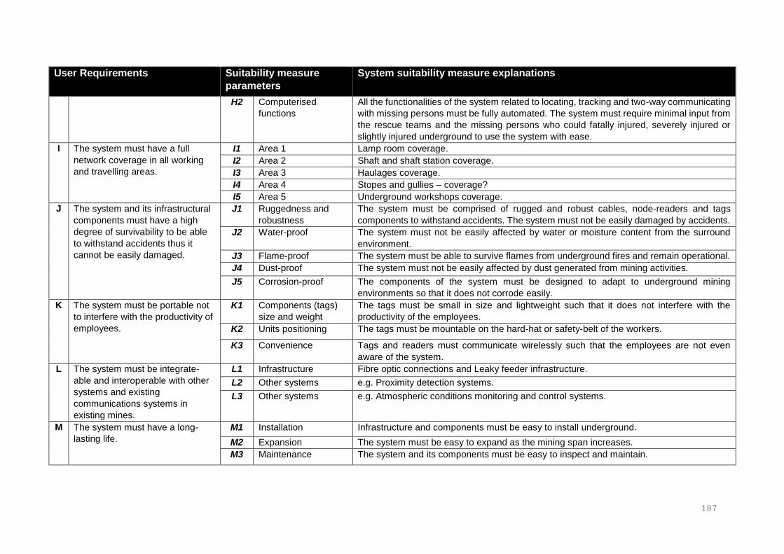
187
User Requirements Suitability measure
parameters
System suitability measure explanations
H2 Computerised
functions
All the functionalities of the system related to locating, tracking and two-way communicating
with missing persons must be fully automated. The system must require minimal input from
the rescue teams and the missing persons who could fatally injured, severely injured or
slightly injured underground to use the system with ease.
I The system must have a full
network coverage in all working
and travelling areas.
I1 Area 1 Lamp room coverage.
I2 Area 2 Shaft and shaft station coverage.
I3 Area 3 Haulages coverage.
I4 Area 4 Stopes and gullies – coverage?
I5 Area 5 Underground workshops coverage.
J The system and its infrastructural
components must have a high
degree of survivability to be able
to withstand accidents thus it
cannot be easily damaged.
J1 Ruggedness and
robustness
The system must be comprised of rugged and robust cables, node-readers and tags
components to withstand accidents. The system must not be easily damaged by accidents.
J2 Water-proof The system must not be easily affected by water or moisture content from the surround
environment.
J3 Flame-proof The system must be able to survive flames from underground fires and remain operational.
J4 Dust-proof The system must not be easily affected by dust generated from mining activities.
J5 Corrosion-proof The components of the system must be designed to adapt to underground mining
environments so that it does not corrode easily.
K The system must be portable not
to interfere with the productivity of
employees.
K1 Components (tags)
size and weight
The tags must be small in size and lightweight such that it does not interfere with the
productivity of the employees.
K2 Units positioning The tags must be mountable on the hard-hat or safety-belt of the workers.
K3 Convenience Tags and readers must communicate wirelessly such that the employees are not even
aware of the system.
L The system must be integrate-
able and interoperable with other
systems and existing
communications systems in
existing mines.
L1 Infrastructure Fibre optic connections and Leaky feeder infrastructure.
L2 Other systems e.g. Proximity detection systems.
L3 Other systems e.g. Atmospheric conditions monitoring and control systems.
M The system must have a long-
lasting life.
M1 Installation Infrastructure and components must be easy to install underground.
M2 Expansion The system must be easy to expand as the mining span increases.
M3 Maintenance The system and its components must be easy to inspect and maintain.

188
User Requirements Suitability measure
parameters
System suitability measure explanations
N The system must be self-
diagnostic.
N1 Battery percentage
indicator
Battery life warning.
N2 Faulty readers and
tags detector
Able to emit and receive signals at the cap lamp room gate and detect faulty tags that will
fail during emergencies. Malfunctional node-readers must also be detected by the system
for replacement or maintenance.
O The system must be cost-effective
for mining operations.
O1 CAPEX The CAPEX of the system must be included in the feasibility study financial models of new
mines. The system must also be affordable such that existing mines can afford to fund
installations of such systems.
O2 OPEX The OPEX of the system includes power consumption, labour costs of operator,
maintenance costs, etc. These costs must form part of the new project OPEX.

189
4.2.2. MISSING PERSON TRACKING AND LOCATOR SYSTEM SUITABILITY
EVALUATION AGAINST USER REQUIREMENTS
The user requirements in Table 23 define a fit for purpose system, which can also be classified
as the most suitable missing person tracking and locator system. Table 24 evaluates the
suitability of the identified systems against the developed user requirements. The aim of this
evaluation was to determine the most suitable systems. The purpose of the requirements is to
guide rescue teams to the locations of missing persons in the quickest possible time.
Therefore, the systems that meet most of these requirements can be seen as the most suitable
systems. The following legend is used to indicate the systems that can be suitable and those
that may be unsuitable.
System potentially suitable
System potentially suitable and unsuitable
System potentially unsuitable
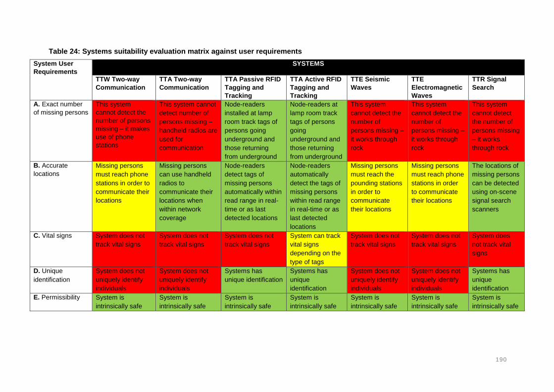
190
Table 24: Systems suitability evaluation matrix against user requirements
System User
Requirements
SYSTEMS
TTW Two-way
Communication
TTA Two-way
Communication
TTA Passive RFID
Tagging and
Tracking
TTA Active RFID
Tagging and
Tracking
TTE Seismic
Waves
TTE
Electromagnetic
Waves
TTR Signal
Search
A. Exact number
of missing persons
This system
cannot detect the
number of persons
missing – it makes
use of phone
stations
This system cannot
detect number of
persons missing –
handheld radios are
used for
communication
Node-readers
installed at lamp
room track tags of
persons going
underground and
those returning
from underground
Node-readers at
lamp room track
tags of persons
going
underground and
those returning
from underground
This system
cannot detect the
number of
persons missing –
it works through
rock
This system
cannot detect the
number of
persons missing –
it works through
rock
This system
cannot detect
the number of
persons missing
– it works
through rock
B. Accurate
locations
Missing persons
must reach phone
stations in order to
communicate their
locations
Missing persons
can use handheld
radios to
communicate their
locations when
within network
coverage
Node-readers
detect tags of
missing persons
automatically within
read range in real-
time or as last
detected locations
Node-readers
automatically
detect the tags of
missing persons
within read range
in real-time or as
last detected
locations
Missing persons
must reach the
pounding stations
in order to
communicate
their locations
Missing persons
must reach phone
stations in order
to communicate
their locations
The locations of
missing persons
can be detected
using on-scene
signal search
scanners
C. Vital signs System does not
track vital signs
System does not
track vital signs
System does not
track vital signs
System can track
vital signs
depending on the
type of tags
System does not
track vital signs
System does not
track vital signs
System does
not track vital
signs
D. Unique
identification
System does not
uniquely identify
individuals
System does not
uniquely identify
individuals
Systems has
unique identification
Systems has
unique
identification
System does not
uniquely identify
individuals
System does not
uniquely identify
individuals
Systems has
unique
identification
E. Permissibility System is
intrinsically safe
System is
intrinsically safe
System is
intrinsically safe
System is
intrinsically safe
System is
intrinsically safe
System is
intrinsically safe
System is
intrinsically safe

191
System User
Requirements
SYSTEMS
TTW Two-way
Communication
TTA Two-way
Communication
TTA Passive RFID
Tagging and
Tracking
TTA Active RFID
Tagging and
Tracking
TTE Seismic
Waves
TTE
Electromagnetic
Waves
TTR Signal
Search
F. Reliability System
infrastructure can
be easily damaged
during accidents
System
infrastructure can
be easily damaged
during accidents
System
infrastructure can
be easily damaged
during accidents
System
infrastructure can
be easily
damaged during
accidents
System is
independent of
infrastructure
System is
independent of
infrastructure
System is
independent of
infrastructure
G. Two-way
communication
Two-way voice
communication
between phone
stations in real-
time
Two-way voice, text
and data
communication
using handheld
radios
Two-way data (light
flashes or beep
sound)
communication
(depending on the
type of tags used)
Two-way data
(light flashes or
beep sound)
communication
(depending on the
type of tags used)
Communication
procedures
followed (when to
start pounding
after hearing
surface blast)
Two-way voice,
text and data
communication at
the system
stations
Two-way data
(light flashes or
beep sound)
communication
(depending on
the type of tags
used)
H. Automation The missing
persons must
operate the system
to communicate
their locations
The missing
persons must
operate the system
to communicate
their locations
Node-readers
detect tags that are
within read range
electronically
Node-readers
detect tags that
are within read
range
electronically
The missing
persons must
operate the
system to
communicate
their locations
The missing
persons must
operate the
system to
communicate
their locations
Signal search
scanner is used
to detect tags of
missing persons
I. Network
coverage
Systems is station
based
Network coverage
is determined by
the installation of
node-readers
Network coverage
is determined by
the installation of
node-readers
Network coverage
is determined by
the installation of
node-readers
Systems is station
based
Systems is station
based
Network
coverage is not
required
J. Survivability System
infrastructure likely
to be damaged
during accidents
System
infrastructure likely
to be damaged
during accidents
System
infrastructure likely
to be damaged
during accidents
System
infrastructure
likely to be
damaged during
accidents
System is
independent of
infrastructure
System is
independent of
infrastructure
System is
independent of
infrastructure

192
System User
Requirements
SYSTEMS
TTW Two-way
Communication
TTA Two-way
Communication
TTA Passive RFID
Tagging and
Tracking
TTA Active RFID
Tagging and
Tracking
TTE Seismic
Waves
TTE
Electromagnetic
Waves
TTR Signal
Search
K. Portability Phones are
installed in stations
Handheld radio
units are small in
size and lightweight
Wearable tags are
in size and
mounted on the
helmet or safety
belt
Wearable tags
(small in size,
lightweight and
mounted on
helmet or safety
belt)
Missing persons
must locate the
pounding station
Loop antenna and
transceivers are
installed in
stations
Wearable tags
L. Integrate-ability
and inter-
operability
Other systems can
be used together
with this system
(e.g. ZigBee
readers)
Other systems can
be used together
with this system
(e.g. vehicle
tracking)
Other systems can
be used together
with this system
(e.g. vehicle
tracking)
Other systems
can be used
together with this
system (e.g.
vehicle tracking)
System cannot be
used for other
purposes
System cannot be
used for other
purposes
Other systems
can be used
together with
this system
M. Long lasting life System requires
inspection and
maintenance
System requires
inspection and
maintenance
System requires
inspection and
maintenance
System requires
inspection and
maintenance
System requires
inspection and
maintenance
System requires
inspection and
maintenance
System requires
inspection and
maintenance
N. Self-diagnosis System does not
have self-diagnosis
capability
System can detect
faulty tags and low
power levels
System can detect
faulty tags and low
power levels
System can
detect faulty tags
and low power
levels
System does not
have self-
diagnosis
capability
System does not
have self-
diagnosis
capability
System can
detect faulty
tags and low
power levels
O. Cost-
effectiveness
Cost analysis was
not part of the
scope
Cost analysis was
not part of the
scope
Cost analysis was
not part of the
scope
Cost analysis was
not part of the
scope
Cost analysis was
not part of the
scope
Cost analysis was
not part of the
scope
Cost analysis
was not part of
the scope

193
In Table 24, the suitability of the identified systems was evaluated against the developed user
requirements:
No single system could satisfy all the user requirements. Different systems could
satisfy different specifications of the user requirements.
TTW Two-way Communication system could meet 5 out of the 15 user requirements.
This system can still be used to find missing persons in circumstances where network
is not damaged and the missing persons can reach the phone station and
communicate their locations.
TTW Two-way Communication system could meet 8 out of the 15 developed user
requirements. This system requires network coverage and the missing persons must
be able to communicate their locations.
TTA Tagging and Tracking (active and passive RFID) systems could meet 11 out of
the 15 developed user requirements. The major shortcoming of these systems is the
susceptibility to damage during accidents and unavailability post-accident. These
systems can be very effective if the infrastructure has a higher survivability.
TTE Seismic and Electromagnetic Waves systems could meet 6 out of the 15
developed user requirements.
TTR Signal Search system could meet 10 out of the 15 developed user requirements.
This system is similar to the TTA Tagging and Tracking system except that it requires
the rescue teams to search for the missing persons in close proximity.
No system could meet the user requirement C (mortality indication – tracking vitals) in
the listed systems. However, in Chapter 2, a Smartwatch device from EasyM2M
(classified as TTA Active RFID Tagging and Tracking) was identified and it can track
vital signs while the normal tags cannot track vital signs.
The system user requirements were developed and recommended for evaluating the
effectiveness of locator, tracking and communication systems. The user requirements serve
to represent an ideal system that operates to full satisfaction in all possible accident scenarios.
The importance of evaluating locator, tracking and communication systems was realised as
the need to:
Improve the effectiveness of existing systems and technologies
Improve future systems
Combine different systems and/or devices to improve effectiveness
Modify current and future designs
Develop new and innovative technologies
The resulting improvement of current systems according to the proposed user requirements
will ensure an effective process of saving lives. The effective process will ensure that rescue
teams reach out to missing persons in the shortest possible time. Locator, tracking and two-
way communication systems are presented in four phases of effectiveness.

194
4.3. APPLICATION OF SYSTEMS IN UNDERGROUND AREAS
From the past accidents, it was found that accidents can occur at anytime and anywhere
underground due to the failure of control measures. As a result of these accidents, the miners
can become trapped in unknown locations in various areas underground. The underground
mining environments are comprised of several areas where people are expected to work and
travel during shift hours. These areas differ in length, cross-sectional area dimensions,
atmospheric conditions, etc. These factors can affect the suitability and applicability of a
systems in the underground areas. One of the key factors, is the ability to transmit signals
sufficiently between surface and underground. These signals carry the location related
information of the miners while working or travelling underground. Miners sometimes move
between working areas and travel long distances. These areas include:
The lamp room,
Shaft (or decline),
Shaft stations,
Haulages,
Refuge bays,
Workshops, and
Stopes/face.
Given these different underground areas – can the selected or chosen system work optimally
in all these areas? Some of the systems are comprised of bigger components which can affect
the applicability in confined spaces such as the stopes. The installation of infrastructure
underground is a challenge especially in confined spaces. Furthermore, the stopes are
frequently advancing, and this requires the systems and its infrastructure to be extended
simultaneously with the advancing stopes. Some of the areas underground are large
excavations and this requires longer read range and high data capacity node-readers to track
people in proximity.
The system components may not fit properly in some of these areas such as the stopes in
narrow reef mines. Some of the components may be intrinsically unsafe to install at the face
especially in explosive gas prone areas. Therefore, there are several factors that can affect
the applicability of systems in the various underground areas. Table 25 highlights the
underground areas, discusses what will be required from the system as well as the suitable
system options. The systems options only show the suitable systems regardless of the level
of suitability. This is because the level of suitability is mainly determined by the user
requirements as evaluated in the previous section.

195
Table 25: System application in different underground areas
Location Requirements Suitable systems in each area
Lamp room Determine the exact number of missing persons post-accident and after survivors have been evacuated.
Provide the unique identifications for the missing persons post-accident.
Tests if all tags are in good working order before person proceeds underground.
Enable two-way communication in case of an emergency whilst in the lamp room.
TTW Two-way Communication The lamp room must consist of telephones that can be used for
two-way voice communication. The phones should be used to communicate with the control room
in case of an emergency. TTA Two-way Communication
Mine workers should be in possession of handheld radio units connected to node-readers wirelessly.
The radios should provide two-way voice communication. TTA Tagging and Tracking
Gate pass at the entrance of the shaft for miners going underground and those returning from underground.
The gate should test if the tags carried by the miners are in good working order and reports faulty tags detected.
Shaft Determine the exact number of people inside the shaft cage.
Track the persons who are inside the shaft cage with depth.
Enable two-way communication between persons in the cage and the control room in case of an emergency.
TTW Two-way (voice) Communication A telephone must be present in the shaft to establish two-way
communication with persons potentially trapped inside the shaft cage.
TTA Two-way (voice) Communication Handheld radios must be carried by the persons in cage (e.g.
supervisors) when inside the cage. TTA Tagging and Tracking
Track the tags carried by the miners who are inside the shaft.
Shaft station Track the real-time locations persons who are exiting from the shaft cage.
Track the real-time persons who are boarding into the shaft cage.
TTW Two-way Communication The lamp room must consist of telephones that can be used for
voice communication to surface. TTA Two-way Communication
Mine workers can be in possession of handheld radios connected to node-readers.
TTA Tagging and Tracking Track the miners who are within the shaft station through tagging
and tracking. Node-readers must be installed at the shaft station to track the
tags carried by the miners present at the shaft station.

196
Location Requirements Suitable systems in each area
Haulages/travelling way
Track the locations of all the persons travelling and working in the haulages in real-time.
The last know locations must also be stored frequently in case the system is damaged.
Adjust the tracking proximities to increase accuracy in critical areas.
Determine the direction in which the missing persons were travelling on a reader-to-reader basis.
Enable two-way communication between persons who are far apart from each other.
TTA Two-way Communication Enable two-way communication throughout haulages using
handheld radio units. TTA Tagging and Tracking
Track the miners travelling and working in the haulages through tagging and tracking.
Track transportation vehicles and the persons inside the vehicles as they travel.
Node-readers detect tags that are within read range. The spacing of node-readers must be considered to avoid blind
spots and overlapping coverage range. Ensure that adjustable tracking is sufficient. Ensure there are no blind spots between the readers and ensure
there is no excessive overlapping in coverage of the node-readers apart.
Refuge bays Determine the number of persons inside the refuge bays.
Provide the real-time locations and last detected locations of the persons present in the refuge bay.
Enable two-way communication between the persons in the refuge bay with control room on surface in real time.
TTA Tagging and Tracking Gate pass to determine the number of persons inside the refuge
bay and node-readers installed to track persons arriving or entering the refuge bay.
TTW Two-way (voice) Communication A telephone must be present inside the refuge bay.
TTA Two-way Communication Enable two-way communication using handheld radio units.
TTE Seismic Waves This system can be installed as back-up to the tagging and
tracking system which may fail due to damage in its infrastructure. TTE Electromagnetic Waves
Similar to the TTE Seismic waves system, it should also provide back-up to the tagging and tracking system.
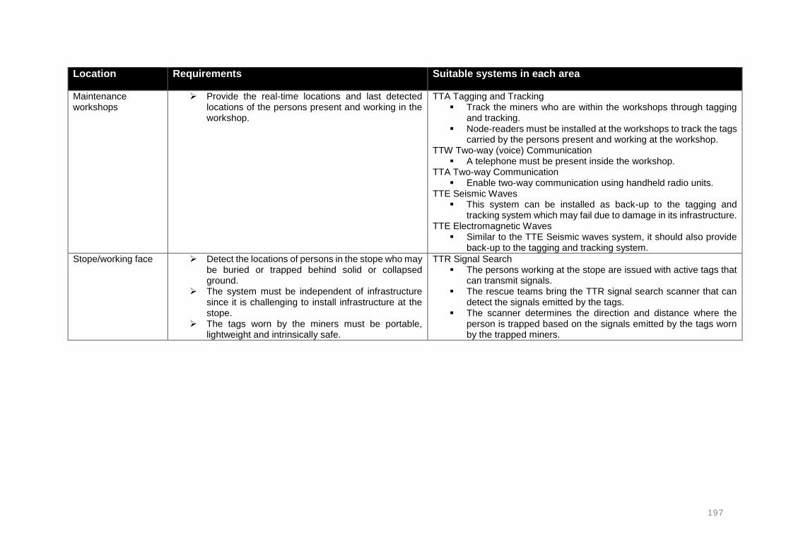
197
Location Requirements Suitable systems in each area
Maintenance workshops
Provide the real-time locations and last detected locations of the persons present and working in the workshop.
TTA Tagging and Tracking Track the miners who are within the workshops through tagging
and tracking. Node-readers must be installed at the workshops to track the tags
carried by the persons present and working at the workshop. TTW Two-way (voice) Communication
A telephone must be present inside the workshop. TTA Two-way Communication
Enable two-way communication using handheld radio units. TTE Seismic Waves
This system can be installed as back-up to the tagging and tracking system which may fail due to damage in its infrastructure.
TTE Electromagnetic Waves Similar to the TTE Seismic waves system, it should also provide
back-up to the tagging and tracking system.
Stope/working face Detect the locations of persons in the stope who may be buried or trapped behind solid or collapsed ground.
The system must be independent of infrastructure since it is challenging to install infrastructure at the stope.
The tags worn by the miners must be portable, lightweight and intrinsically safe.
TTR Signal Search The persons working at the stope are issued with active tags that
can transmit signals. The rescue teams bring the TTR signal search scanner that can
detect the signals emitted by the tags. The scanner determines the direction and distance where the
person is trapped based on the signals emitted by the tags worn by the trapped miners.

198
In Table 25, the identified systems were evaluated against the various underground areas
where people are expected to work and travel:
No single system could work in all the underground areas from the systems that were
identified and evaluated in the previous sections.
TTW Two-way Communication systems work in fixed areas such as refuge bays, shaft
stations and lamp room. Two-way, real-time communication can significantly improve
the effectiveness of a search-and-rescue operation. This allows the missing persons
to cooperate with the rescue teams in the process.
TTA Two-way Communication and TTA Tagging and Tracking system can work in
most of the areas where infrastructure is available, except at the stopes where it is
challenging to install node-readers. The stopes are confined and continuously
advancing requiring the systems to be extended.
TTE Seismic Waves and TTE Electromagnetic Waves systems also work in fixed areas
(stations) and shallow depth mines such as the coal mines in the South African mining
industry. These systems are not applicable in the ultradeep gold and platinum mines
due to the limited propagation distance of signals through rock. However, these
systems can be critical in post-accidents where the primary system and its
infrastructure are damaged. These systems do not depend on infrastructure to enable
real-time two-way voice, text and data communication.
Only the TTR Signal Search system can work at the stope because it does not require
any infrastructure. The miners carry active tags that can emit signals which can be
detected by signal search scanners. The signals can penetrate a certain distance
through rock (tested up to 40m in solid and collapsed ground) while the distance can
be larger through the air. This enable the scanners to also detect miners who could be
trapped in cavities or around corners.

199
4.4. GOING MISSING SCENARIOS
There are several scenarios in which miners can go missing underground. These scenarios
are associated with the identified accidents. The going missing scenarios will be used to
evaluate systems that are applicable and have the potential to locate missing persons. The
going missing scenarios will be used to determine the types of systems that have a potential
to locate missing persons associated to these kinds of scenarios. These scenarios will further
be used to determine the types of systems that may fail to locate missing persons in the related
accident scenario. The going missing scenarios in Table 26 were derived from the past mining
accidents. The number of missing persons in these going missing scenarios may vary
according to the nature of the accident.

200
Table 26: Underground accidents or scenarios that lead to miners going missing
Accident Accident-scenario leading to underground missing persons
Methane and coal dust explosion
displacing miners into unknown
locations.
People can go missing as a result of underground methane and coal dust explosions. Persons who
survive the explosions are subjected to inhalation of harmful and toxic gases, which will cause them to
suffocate and collapse in unknown locations. Most of the worst mining accidents, as per the number of
fatalities, have resulted from methane and coal dust explosions. These explosions can, not only kill, but
also trap many people. Explosions have an extended and disastrous area of occurrence and this could
lead to a large number of people being trapped and lost underground. The release of gases from the
explosions causes poor visibility in the mine and this makes the underground situation even worse for
both the trapped persons and rescue teams attempting to locate missing persons.
Miners buried or trapped behind or
under falls of ground and rockbursts
(at the working face and haulages).
Falls of ground are amongst the most common accidents in underground mines. Falls of ground are
mainly caused by seismic events and poor support practices and can occur suddenly and unexpected.
When a fall of ground occurs, a number of things can happen, mine workers can be fatally or seriously
injured, access to the affected area may be blocked and infrastructure can be damaged. Mine personnel
become missing when buried behind or under collapsed ground.
Miners swept into unknown locations
by flooding (or water inundation).
Flooding may result in people being swept away and submerged under an inrush of water. The persons
may be swept away into abandoned workings, cavities or any other unknown locations inside the mine.
The surrounding and overlying rock strata of the mine may contain highly confined water tables. When
disturbed, an inrush of high-pressure water occurs and flooding an extended area of the underground
mine and trapping miners. Water levels in the mine may rise as high as the roof as a result. Water
inundation is capable of sweeping away many people at the same time throughout the underground
workings.

201
Accident Accident-scenario leading to underground missing persons
Miners trapped by underground fires
and the smoke released by the fire
Underground fires usually result from explosions and conveyor belt systems. People may become missing
underground from being trapped by fires. While the rescue teams may not be able to enter underground,
the trapped persons may also be unable to escape from the burning areas. The human eye cannot see
through fire, especially when dense smoke is present. The big challenge with underground fires is that it
burns for a long time and only stops when oxygen has depleted from the underground environment.
Underground fires occur in various scales and this determines the volume of people who could be trapped
during the accident. A number of underground fire accidents with various causes have been reported
previously. With the nature of underground mines, there is a fair chance of happening.
Stuck or submerged in mud due to
mud-rush or being displaced by the
mud-rush incident.
The occurrence of floods and accumulation of high water-levels forms mud around the surface of the
underground workings. The mud may also be covered in water and unnoticeable. Mud is slippery and can
causes slip and fall accidents. If a person could fall on thick layer of mud, they would sink to the bottom
and remain covered and invisible. Mud sticks on the surface of objects in contact with, also making it
difficult to see a person submerged in mud.
Being displaced by air-blast incident
into unknown locations such as
cavities such as ore-passes.
Air-blast, also known as wind-blast, is huge threat in underground coal mines, particularly in longwall and
shor-twall mines where the overlying strata is allowed to collapse (goafing). These accidents are also
common in box-holes or ore-passes in hardrock mines. An air-blast accident can displace workers from
their originals positions into unknown locations.
Vehicle-to-vehicle collision (run-over
or caught in between machines
without being noticed) without being
noticed.
Similar to vehicle-to-persons accidents, the confined working spaces and poor illumination can lead to
vehicle interactions. Some of the vehicles used underground are the low duty vehicles (LDV) that transport
personnel underground. If an LDV is involved in a collision, a large number of people could be killed.
However, it can be assumed that all persons will be found in the vicinity of the accident with less chances
of people go missing due to these accidents.
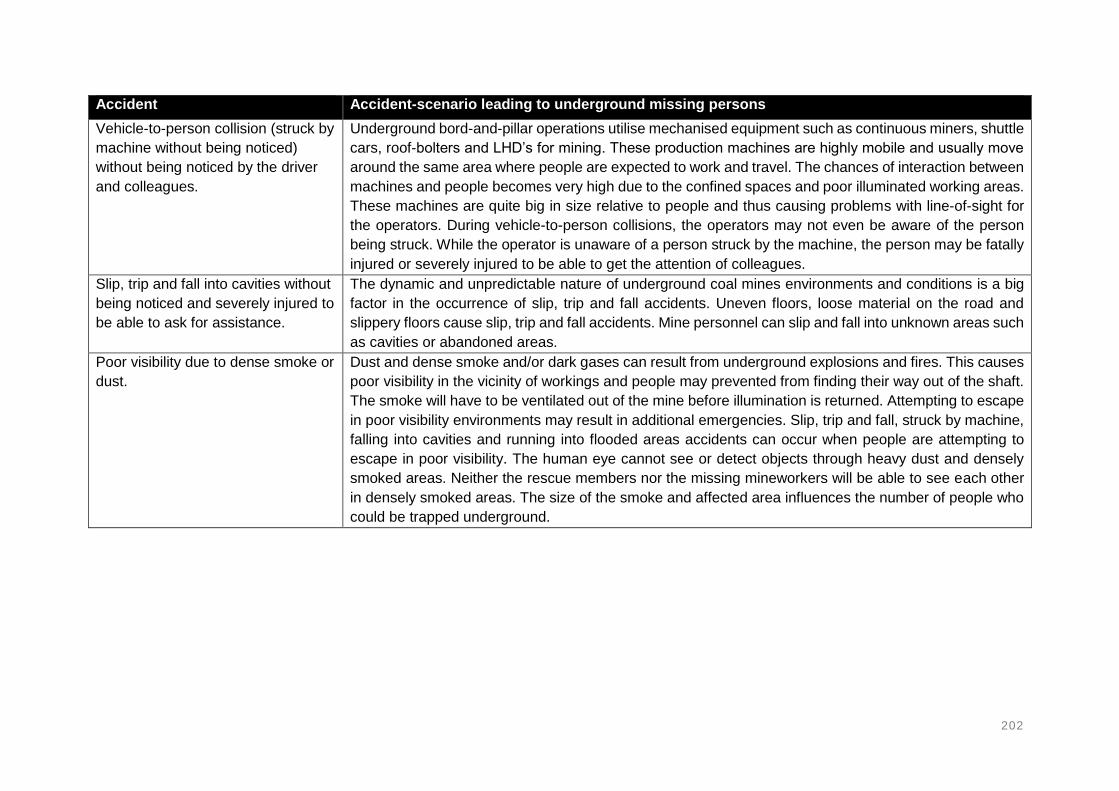
202
Accident Accident-scenario leading to underground missing persons
Vehicle-to-person collision (struck by
machine without being noticed)
without being noticed by the driver
and colleagues.
Underground bord-and-pillar operations utilise mechanised equipment such as continuous miners, shuttle
cars, roof-bolters and LHD’s for mining. These production machines are highly mobile and usually move
around the same area where people are expected to work and travel. The chances of interaction between
machines and people becomes very high due to the confined spaces and poor illuminated working areas.
These machines are quite big in size relative to people and thus causing problems with line-of-sight for
the operators. During vehicle-to-person collisions, the operators may not even be aware of the person
being struck. While the operator is unaware of a person struck by the machine, the person may be fatally
injured or severely injured to be able to get the attention of colleagues.
Slip, trip and fall into cavities without
being noticed and severely injured to
be able to ask for assistance.
The dynamic and unpredictable nature of underground coal mines environments and conditions is a big
factor in the occurrence of slip, trip and fall accidents. Uneven floors, loose material on the road and
slippery floors cause slip, trip and fall accidents. Mine personnel can slip and fall into unknown areas such
as cavities or abandoned areas.
Poor visibility due to dense smoke or
dust.
Dust and dense smoke and/or dark gases can result from underground explosions and fires. This causes
poor visibility in the vicinity of workings and people may prevented from finding their way out of the shaft.
The smoke will have to be ventilated out of the mine before illumination is returned. Attempting to escape
in poor visibility environments may result in additional emergencies. Slip, trip and fall, struck by machine,
falling into cavities and running into flooded areas accidents can occur when people are attempting to
escape in poor visibility. The human eye cannot see or detect objects through heavy dust and densely
smoked areas. Neither the rescue members nor the missing mineworkers will be able to see each other
in densely smoked areas. The size of the smoke and affected area influences the number of people who
could be trapped underground.

203
Accident Accident-scenario leading to underground missing persons
Poor visibility due to loss of power
(electricity or cap lamps).
The underground mining environment is always dark and depends on electric lamps and battery-powered
cap lamps for lighting. Electric power cut off and cap lamps battery damage will result in zero visibility
underground, as there is no other source of lighting. During the loss of visibility, mine workers are stuck
underground as it is unsafe to walk or travel in poor visibility areas. Electric power is supplied underground
through electric cables that can be easily damaged by accidents such as fall of ground and explosions. It
may become difficult and challenging to re-establish power supply for lighting to the entire mine during
emergencies. The rescue teams may use temporary lighting equipment (torches), but this lighting may
not be sufficient to cover all spaces or spots where people could be trapped. While the temporary lighting
is insufficient to light up the entire mine, mine workers could be trapped or lost anywhere underground,
unable to call for help in the case of fatal injuries or when seriously injured.
Unauthorised entry into abandoned
and sealed off workings.
Underground bord-and-pillar mining consist of large areas of abandoned workings where people are not
allowed to enter without authorisation. Mine workers can be lost in abandoned areas. Mine workers are
known to have the tendency of entering these sealed off workings in order to rest and take prolonged
breaks, unnoticed. The mine workers are known to enter in the sealed workings to even sleep during
working hours. During an emergency, nobody will know or become aware of the people that have entered
into the abandoned areas. This accident is seen as an intentional scenario where mine workers put their
lives at risk knowingly. Therefore, the severity and frequency of these accidents depends solely on the
behaviour of the workers.
New employee lost underground.
The new employees may get lost underground during the first few months of work. The new employees
become familiar and experienced within the underground workings with time. In addition, during the early
stages of working, the new employees are under supervision.
Fraudulent clocking or bypassing the
clocking in system in and out of the
shaft and inefficient clocking
systems.
Fraudulent clocking is serious issue in underground operations where employees cover up for each other.
Workers clock in-and-out of the shaft for absent workers using their clock-cards. Fraudulent clocking
makes it difficult to quantify the actual number of mineworkers missing underground after an accident
occurred. After an accident occurs, the clock in-and-out system will indicate more people missing than
the actual due to fraudulent clocking. The clock system may indicate a certain number of people to be
missing underground while there is actually fewer people than indicated. The rescue teams may risk their
lives searching for people that never reported for work, but only their clock cards were used.

204
Accident Accident-scenario leading to underground missing persons
Illegal mining activities (this scenario
is not common, but has chance of
happening)
Illegal miners and cable thieves are a threat to the lives of the mine workers and they can hold mine
workers hostages. These people can kill and hide the bodies of the workers to steal their rescue packs
and cap lamps. Illegal mining may complicate search-and-rescue missions as the bodies of mineworkers
held hostages by illegal miners can be hidden underground.
Being incapacitated and collapse in
unknown areas due to heat
exhaustion.
Heat exhaustion can cause workers underground to be incapacitated and collapse. These persons can
collapse in unknown areas without the knowledge of other workers who could assist. As a result, the
persons can be lost underground.

205
4.5. EVALUATION OF MISSING LOCATOR SYSTEMS AGAINST ACCIDENT
SCENARIOS
In Table 26, a set of accident scenarios in which miners went missing underground was
shown. Table 26 shows 16 different accident scenarios in which people went missing in the
past. However, it should be noted that these are not the only possible going missing scenarios.
Furthermore, different mines experience different types of accidents which influences the
frequency and magnitude of the going missing scenarios. It was now necessary to identify the
suitability of available missing person tracking and locator systems (as identified before) to
each of these accident scenarios. The suitability of a system to an accident scenario is based
on Table 22, which shows the capabilities and limitations of the respective available systems.
However, the suitability of the respective available systems to the accident scenarios can also
be influenced by the area underground in which the accident occurred. Table 26 shows the
systems suitable and those unsuitable for each scenario. The reasons for suitability or
unsuitable are also given.

206
Table 27: Suitability of available systems versus accident scenarios
Accident
scenario
Potentially suitable systems Reason why system may be suitable Potentially unsuitable systems Reason why system may be
unsuitable
Methane and coal dust explosion
TTR Signal Search TTE Seismic Waves TTE Electromagnetic
Waves
These systems do not require any major infrastructure and therefore can survive a methane gas and coal dust explosion
These systems can be relocated as close as possible to areas where people are working for easy access and use by the missing persons
TTW Two-way Communication TTA Two-way Communication TTA Passive RFID Tagging and
Tracking TTA Active RFID Tagging and
Tracking
Underground explosions (depending on severity and area of occurrence) may result in the system and its infrastructure being damaged and therefore the system will not be able to track or locate the missing persons
Fall of ground and rock-burst at the working face
TTE Seismic Waves TTE Electromagnetic
Waves TTR Signal Search
These systems do not require any major infrastructure and therefore can survive a fall of ground incident
These systems can be relocated as close as possible to areas where people are working
TTW Two-way Communication TTA Two-way Communication TTA Passive RFID Tagging and
Tracking TTA Active RFID Tagging and
Tracking
Fall of ground (depending on severity and area of occurrence) may result in the system and its infrastructure being damaged and therefore the system will not be able to track or locate the missing persons
Flooding (water inundation)
TTE Seismic Waves TTE Electromagnetic
Waves TTR Signal Search
These systems are unlikely to be affected by underground flooding and can still be used by the missing persons (depending on the severity of the water inundation)
TTW Two-way Communication TTA Two-way Communication TTA Passive RFID Tagging and
Tracking TTA Active RFID Tagging and
Tracking
These systems and their infrastructure may be damaged by the flooding and therefore cannot detect the missing persons
Underground Fires
TTE Seismic Waves TTE Electromagnetic
Waves TTR Signal Search
These systems are unlikely to be affected by underground fires and can still be used by the missing persons (depending on the severity of the fire)
These systems can be relocated as close as possible to areas where people are working
TTW Two-way Communication TTA Two-way Communication TTA Passive RFID Tagging and
Tracking TTA Active RFID Tagging and
Tracking
These systems and their infrastructure may be damaged by the fire and therefore cannot detect the missing persons

207
Accident
scenario
Potentially suitable systems Reason why system may be suitable Potentially unsuitable systems Reason why system may be
unsuitable
Being swept by mud-rush and getting stuck or submerged in accumulated mud on the floor
TTA Passive RFID Tagging and Tracking
TTA Active RFID Tagging and Tracking
TTR Signal Search
Missing persons can be detected through tag-to-reader communication as well as two-way text or voice communication
TTW Two-way Communication TTE Seismic Waves TTE Electromagnetic Waves
The missing persons may be unable to reach systems stations
The missing persons may be unable to communicate their locations if severely injured
Being blown away by air-blast into unknown areas
TTA Two-way Communication
TTA Passive RFID Tagging and Tracking
TTA Active RFID Tagging and Tracking
TTR Signal Search
Missing persons can be detected through tag-to-reader communication as well as two-way text or voice communication
TTW Two-way Communication TTE Seismic Waves TTE Electromagnetic Waves
The missing persons may be unable to reach systems stations
The missing persons may be unable to communicate their locations if severely injured
Vehicle-to-person collision - struck by machine
TTA Passive RFID Tagging and Tracking
TTA Active RFID Tagging and Tracking
TTR Signal Search
Even if the missing persons can be injured during collision, they can still be detected through tag-to-reader communication
TTW Two-way Communication TTA Two-way Communication TTE Electromagnetic Waves TTE Seismic Waves
If the missing persons are injured during collision, they will be unable to reach system station
Vehicle-to-vehicle collision
TTA Passive RFID Tagging and Tracking
TTA Active RFID Tagging and Tracking
TTR Signal Search
Even if the missing persons can be injured during collision, they can still be detected through tag-to-reader communication
TTW Two-way Communication TTA Two-way Communication TTE Seismic Waves TTE Electromagnetic Eaves
If the missing persons are injured during collision, they will be unable to reach system station
Poor visibility due to dense smoke or dust
TTA Two-way Communication
TTA Passive RFID Tagging and Tracking
TTA Active RFID Tagging and Tracking
TTR Signal Search
Missing persons can be detected through tag-to-reader communication
TTW Two-way Communication TTA Two-way Communication TTE Seismic Waves TTE Electromagnetic Waves
The missing persons may be unable to reach system stations due to the poor visibility

208
Accident
scenario
Potentially suitable systems Reason why system may be suitable Potentially unsuitable systems Reason why system may be
unsuitable
Poor visibility due to loss of power (electricity or cap lamps)
TTA Two-way Communication
TTA Passive RFID Tagging and Tracking
TTA Active RFID Tagging and Tracking
TTR Signal Search
Missing persons can be detected through tag-to-reader communication
TTW Two-way Communication TTA Two-way Communication TTE Seismic Waves TTE Electromagnetic Waves
The missing persons may be unable to reach system stations due to the poor visibility
Unauthorised entry into abandoned and sealed off workings
TTA Passive RFID Tagging and Tracking
TTA Active RFID Tagging and Tracking
These systems can detect when persons are persons are outside the tracking zones
TTW Two-way Communication TTA Two-way Communication TTE Seismic Waves TTE Electromagnetic Waves TTR Signal Search
These systems cannot track the zones where persons work and travel
Slip, trip and fall into cavities
TTA passive RFID tagging and tracking systems
TTA Active RFID Tagging and Tracking
TTR Signal Search
Missing persons wearing tags can be detected by node-readers and signal search scanners
TTW Two-way Communication TTA Two-way Communication TTE Seismic Waves TTE Electromagnetic Waves
Missing may be unable to reach systems stations or communicate if injured during slip, trip and fall incident
Novices lost underground by host
TTW Two-way Communication
TTA Two-way Communication
TTA Passive RFID Tagging and Tracking
TTA Active RFID Tagging and Tracking
TTE Seismic Waves TTE Electromagnetic
Waves TTR Signal Search
TTA Tagging and Tracking - if novices are also issued with tags, then they can be detected by node-readers or the signal search scanners
TTA Two-way Communication - if novices are issued with handheld radios, then they can communicate their locations
TTE and TTW Two-way Communications – if the novices manage to reach system stations, then they can communicate their locations
TTW Two-way Communication TTA Two-way Communication TTA Passive RFID Tagging and
Tracking TTA Active RFID Tagging and
Tracking TTE Seismic Waves TTE Electromagnetic Waves TTR Signal Search
Novices may not be wearing any tags and therefore they cannot be detected by node-readers
Novices may be unable to reach systems stations due to being unfamiliar with the mine visited
Fraudulent clocking in and out of the shaft
TTA Passive RFID Tagging and Tracking
TTA Active RFID Tagging and Tracking
These systems have a unique identification function, and this can prevent fraudulent clocking
TTW Two-way Communication TTA Two-way Communication TTE Seismic Waves TTE Electromagnetic Waves TTR Signal Search
These systems do not have the unique identification function and therefore cannot detect fraudulent clocking

209
Accident
scenario
Potentially suitable systems Reason why system may be suitable Potentially unsuitable systems Reason why system may be
unsuitable
Illegal mining activities leading to worker being held hostages
TTA Passive RFID Tagging and Tracking
TTA Active RFID Tagging and Tracking
TTR Signal Search
The locations of the missing persons held hostages can be detected through a tag-to-reader communication
TTW Two-way Communication TTA Two-way Communication TTE Seismic Waves TTE Electromagnetic Waves
The missing persons will not be able to reach the stations of these systems to communicate their locations due to being held hostages
Heat exhaustion
TTA Passive RFID Tagging and Tracking
TTA Active RFID Tagging and Tracking
TTR Signal Search
These systems do not require the missing persons to use the systems as tags worn by the missing persons will be detected electronically by node-readers
TTW Two-way Communication TTA Two-way Communication TTE Seismic Waves TTE Electromagnetic Waves
The missing person may be incapacitated and therefore unable to reach the stations of these systems
The missing person may be incapacitated and therefore unable to communicate their locations
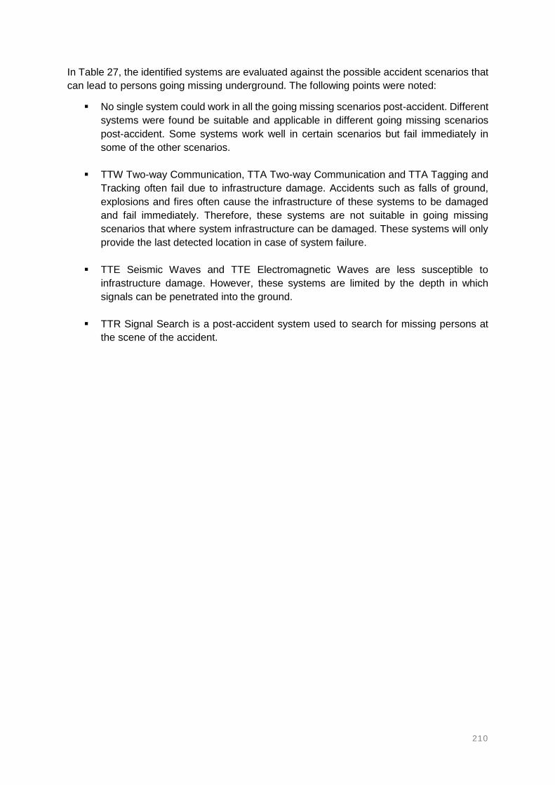
210
In Table 27, the identified systems are evaluated against the possible accident scenarios that
can lead to persons going missing underground. The following points were noted:
No single system could work in all the going missing scenarios post-accident. Different
systems were found be suitable and applicable in different going missing scenarios
post-accident. Some systems work well in certain scenarios but fail immediately in
some of the other scenarios.
TTW Two-way Communication, TTA Two-way Communication and TTA Tagging and
Tracking often fail due to infrastructure damage. Accidents such as falls of ground,
explosions and fires often cause the infrastructure of these systems to be damaged
and fail immediately. Therefore, these systems are not suitable in going missing
scenarios that where system infrastructure can be damaged. These systems will only
provide the last detected location in case of system failure.
TTE Seismic Waves and TTE Electromagnetic Waves are less susceptible to
infrastructure damage. However, these systems are limited by the depth in which
signals can be penetrated into the ground.
TTR Signal Search is a post-accident system used to search for missing persons at
the scene of the accident.

211
4.5. FACTORS OF CONSIDERATION FOR SYSTEM IMPLEMENTATION
The suitability of a system can be affected by other factors that are independent of the
capabilities of the system and its infrastructure. These factors cannot be used for evaluating
the suitability of the systems but can affect its suitability and applicability in underground
mining operations. A thorough understanding and analysis of these factors can influence the
selection of a suitable and fit for purpose system. Once a missing person tracking, two-way
communication or locator system has been selected, this will require that the system or
systems are implemented accordingly at the expense of these factors. This will ensure
maximum value is derived from the systems. Table 28 highlights several factors that should
be considered for ensuring that the selected system is implemented accordingly.
The factors of consideration are classified according to different phases of implementing a
missing person tracking, two-way communication and locator system. The implementation
phases classify the systems in order of suitability level. The implementation phases should be
appraised properly to ensure that the capabilities of the system are able to satisfy the proposed
user requirements, work in the underground areas and be suitable in the possible going
missing scenarios. The implementation phases include; the system selection phase, the
system installation planning phase, the system operational planning phase, and the system
post-implementation planning phase as shown in Table 28.

212
Table 28: Phases of system implementation planning
Phase Parameter of consideration
System selection Identification and evaluation of possible systems
System functionalities analysis versus type of mine (e.g. bord-and-pillar)
and depth
Tagging and Tracking
Two-way communication
TTE communication
On-scene search
System capabilities analysis – determined by user requirements and going
missing scenarios
TTR detection distance and direction
Read range of node-readers and spacing apart
Capacity tracking – number of tags detectable simultaneously
System limitations analysis – mine method and depth taken into
consideration
Maximum depth of penetration for TTE signal propagation
TTA signal propagation interferences objects (e.g. metals)
Market analysis of selected system
Availability of systems in the market
System costs
CAPEX
OPEX
Installation of system Data transmission infrastructure – TTW/TTA/TTE
Infrastructure protection
Redundancy of data transmission system
Cable connections versus wireless mesh network system
Reliable, continuous and backup power supply to system
Strategic installation of system components
Distance apart/read range
Issuing of system units to employees (e.g. tags)
Unique identification
Operation of system Employee engagement and system acceptance
Need and value of the system
Stakeholder engagement
System usage and maintenance skills and training
Installation and operational time frame
Post-implementation of
system
System inspection
Identification of faulty/damaged components
System maintenance
Proactive/preventative/predictive/reactive maintenance
System replacement time frame
Life span of the system
Conducting of test drills
How often should test drills be conducted?
System integration and inter-operability
Which other systems can work together with this system in the
future (e.g. collision avoidance and fleet management)
System effectiveness and performance evaluation
Is the system performing as per design?
Where and how could the system be improved?

213
4.6. INTEGRATION OF SYSTEMS FOR IMPROVED SUITABILITY
The evaluation of systems against the user requirements, underground areas and going
missing scenarios shows that there is a need for systems integration to improve suitability,
applicability and effectiveness. Systems integration refers to the process of combining
different systems to function as a single system. This is done to benefit from the advantages
of each of the different systems while overcoming the limitations of the systems. The main
purpose of integrating systems is to improve the speed of search-and-rescue operations in
order to find missing persons as quickly as possible. The higher the suitability of the system,
the quicker missing persons can be found and rescued.
One of the key findings was that there is no single system that can satisfy all the system user
requirements, underground areas and the going missing scenarios in any circumstance. As a
result, it was decided to assess the possibility and effect of combining different systems to
function as a single system. The integration of systems can be classified according to the
suitability or level of effectiveness of the identified systems in terms of satisfying the user
requirements, underground areas and the going missing scenarios.
Figure 69 shows an overall summary of how the systems were evaluated and found to be
suitable according to the user requirements, underground areas and accident scenarios. This
diagram can be used to determine, not only the most suitable system, but also the more
applicable system to a specific mine and for specific accidents. The specific mines take into
consideration the underground areas and the going missing scenarios that are mostly
associated with that specific mine. This is because the underground areas and types of
accidents may be different from one mine to another. The going missing scenarios are also
different from one mine to another in terms of the frequency and severity of the accidents.
Accident frequency and magnitude are influential to the suitability of a systems on the going
missing scenarios. Some of the factors that should be taken into consideration for systems
integrations:
The availability of infrastructure in existing mines or the choice of infrastructure in new
mines e.g. TTA Tagging and Tracking, and TTA Two-way Communication systems
should be operated over the same backbone infrastructure;
The inter-operability of components of the systems being combined e.g. the active tags
used for the TTA tagging and tracking system should also be detectable by a TTR
signal search scanner;
Components of the systems must be intrinsically safe e.g. TTA Two-way handheld
radios may be used at the stopes/face; and
Tracking, two-way communication and locator systems should further incorporate
additional or auxiliary functions and features to improve the effectiveness of finding
missing persons.
The developed user requirements give an idea of some of the features that can be integrated
into the systems such as the vitals tracking feature. This can also be used to help with the
prioritisation of which missing person to rescue first during a search-and-rescue operation, for
example - tracking the vitals of the missing miners to determine if the missing person is still
alive or not. Therefore, the rescue teams can decide to rescue a person who is still alive over
a deceased person. This can play a significant role in focusing rescue efforts and subsequently
save the lives of survivors.
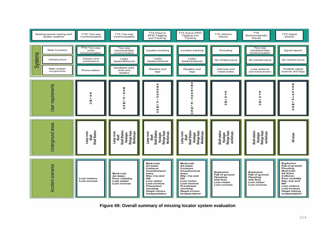
214
Figure 69: Overall summary of missing locator system evaluation

215
A combination of systems or technologies provide the opportunity to improve the effectiveness
and suitability of the systems. It would be ideal to combine these systems such that they
function as a single system with multiple functions and capabilities. For an example, one
system that integrates features of other systems would benefit from the capabilities of those
systems and subsequently increase the effectiveness and suitability of the system. The size
of the component should also remain as small as possible in order to avoid interfering with the
productivity of the mine employees during normal working hours.
Example of how the diagram in Figure 69 can be used to select, not only a suitable, but also
a more applicable system. This diagram also shows how the different systems can integrated
to close any gaps during search-and-rescue operations.
1. Identify the most common accident and this will give an indication of the most likely
going missing scenarios in the mine;
o E.g. Fall of ground – miner trapped behind rock fall or buried in rock fall
2. Rank systems suitability according to the going missing accident scenarios and select
the top ranked systems;
3. Rank systems suitability according to the type of mine – which is characterised by the
underground areas;
4. Compare the rankings in (2) and (3) and look for commonalities in the suitability of the
selected systems;
5. Rank systems suitability according to user requirements;
6. Compare rankings in (2), (3) and (4); and
7. Use the comparisons in (1) to (6) to determine the most suitable and applicable system.
Table 28 gives an example of how different systems can be integrated to provide an effective
and suitable system. This system allows TTA Two-way Communication together with TTA
Tagging and Tracking systems to operate over the same infrastructure. The Tagging and
Tracking system provides more accurate locations in real-time. The two-way communication
system allows rescue teams to communicate with missing persons in real-time. The on-scene
locator and signals search enables the rescue teams to search for the missing persons if the
other systems are damaged during an accident.

216
Table 29: An example of an integrated system
Functionality Factors of consideration
Infrastructure TTW
Communication
Provide network coverage underground (full network coverage)
Real-time data transmission between surface and underground
Data transmission technique (TTW, TTA or TTE) and redundancy
Speed of transmission and bandwidth
Integrate-ability and inter-operability with other systems
Locations of the missing persons
TTA Active RFID Tagging and Tracking
Tracking the exact number of persons present underground
Real-time detection of locations
Providing the last detected locations
Unique identification
Temporary tags allocation for visitors
Replacement of faulty tags
Strategic installation of node-readers (shaft, shaft stations, haulages, workshops and stopes)
Read range and spacing of node-readers
Number of tags that can be detected by a single node-reader at the same time
Two-way Communication with the missing person
TTA Two-way Communication
Enable real-time two-way communication
Two-way voice, text and data
Two-way communication between surface-and-underground and between the underground working areas
On-scene Locator TTR Signal
Search Scanners
Backup system (using the same tags of the tagging and tracking system)
Independent of infrastructure
Detection of signals through solid and collapsed rock
Signal scanner interface (distance and direction)
Backup system TTE
Electromagnetic Waves
Vitals tracking (health monitoring and mortality indication)
Livestream video playback
Battery level indication and warning
Integrate-ability with other systems (e.g. collision avoidance systems)
Inter-operability with other systems (e.g. gas levels and temperature monitoring systems)
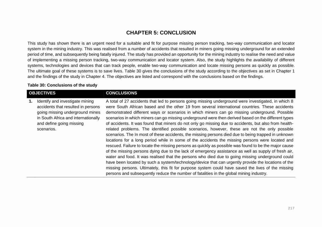
217
CHAPTER 5: CONCLUSION
This study has shown there is an urgent need for a suitable and fit for purpose missing person tracking, two-way communication and locator
system in the mining industry. This was realised from a number of accidents that resulted in miners going missing underground for an extended
period of time, and subsequently being fatally injured. The study has provided an opportunity for the mining industry to realise the need and value
of implementing a missing person tracking, two-way communication and locator system. Also, the study highlights the availability of different
systems, technologies and devices that can track people, enable two-way communication and locate missing persons as quickly as possible.
The ultimate goal of these systems is to save lives. Table 30 gives the conclusions of the study according to the objectives as set in Chapter 1
and the findings of the study in Chapter 4. The objectives are listed and correspond with the conclusions based on the findings.
Table 30: Conclusions of the study
OBJECTIVES CONCLUSIONS
1. Identify and investigate mining
accidents that resulted in persons
going missing underground mines
in South Africa and internationally
and define going missing
scenarios.
A total of 27 accidents that led to persons going missing underground were investigated, in which 8
were South African based and the other 19 from several international countries. These accidents
demonstrated different ways or scenarios in which miners can go missing underground. Possible
scenarios in which miners can go missing underground were then derived based on the different types
of accidents. It was found that miners do not only go missing due to accidents, but also from health-
related problems. The identified possible scenarios, however, these are not the only possible
scenarios. The In most of these accidents, the missing persons died due to being trapped in unknown
locations for a long period while in some of the accidents the missing persons were located and
rescued. Failure to locate the missing persons as quickly as possible was found to be the major cause
of the missing persons dying due to the lack of emergency assistance as well as supply of fresh air,
water and food. It was realised that the persons who died due to going missing underground could
have been located by such a system/technology/device that can urgently provide the locations of the
missing persons. Ultimately, this fit for purpose system could have saved the lives of the missing
persons and subsequently reduce the number of fatalities in the global mining industry.

218
OBJECTIVES CONCLUSIONS
2. Evaluate the availability and
utilisation of systems,
technologies and devices
(including their functions,
capabilities and limitations) that
can track people, enable two-way
communication and locate missing
persons in underground mines.
Through the literature review; systems, technologies and devices that can provide the locations of
missing persons in underground mines were identified and studied. The functions, capabilities and
limitations influencing and affecting the suitability of these systems were evaluated. These systems
are commercially available from various manufacturers worldwide. The systems from the different
manufacturers may be of the same group or class, having similar functions, but may also have unequal
capabilities (e.g. read range and penetration distance through rock). The capabilities and limitations
of the systems were used to determine its suitability of the systems. The systems, technologies and
devices include:
TTW Two-way (voice only) Communication (wired phones)
TTA Two-way (voice/text/data) Communication (handheld portable radios)
TTA Passive RFID Tagging and Tracking (tags and readers and inertial navigation)
TTA Active RFID Tagging and Tracking (tags and readers, underground GPS and mesh
network)
TTE Seismic Waves (pounding – sledgehammer and metal plate)
TTE Electromagnetic Waves (loop antennas and transceivers)
TTR Signal Search
Direct Search Devices (e.g. UAV’s, robotic vehicles, etc.)
It can therefore be concluded that a wide range of systems, technologies and search devices are
available for the mining industry for finding missing persons. Some of these systems are in
development stages, some have been tested for their specific purposes and some are already being
used in existing mining operations.
3. Evaluate the suitability of the
identified systems in (2) against
the going missing scenarios
identified and investigated in (1).
The capabilities and limitations of the identified systems were evaluated against the possible
underground going missing scenarios. This was done to determine which system or systems can be
suitable in which scenarios and if there is any system that can work satisfactorily in all the scenarios.
It was found that there is no single system that can work in all the scenarios to a satisfactory level.
Different systems are suitable for different scenarios. The factors and challenges affecting the systems
or that may cause the system to fail were identified.

219
OBJECTIVES CONCLUSIONS
4. Derive system user requirements
of an ideal system and use these
system user requirements to
evaluate the suitability of the
identified systems.
System user requirements were developed for further evaluating the effectiveness and suitability of
the potential systems. The developed system user requirements will play an integral part during the
phase of selecting a fit for purpose system. The system user requirements were developed based on
a series of critical questions that may arise during an emergency where people have gone missing
underground, following the occurrence on an accident. The system user requirements will not only be
crucial during system selection, but will also:
Help suppliers/manufacturers improve technological limitations in their current systems.
Make suppliers/manufacturers aware of the limitations of their systems and therefore strive to
increase the capabilities of their systems.
Make mining operations aware that a combination of systems can increase the suitability of
locating missing persons.
5. Evaluate the application of the
identified systems into the
different underground travelling
and working areas.
The underground mining environments consists of various areas in which people are expected to work
and travel. These areas are different from each other in terms of layout, dimensions and advance
rates. The identified systems were then evaluated against the different underground working areas. It
was found that no single system could work in all the underground areas. The biggest challenge was
found to be at the stope whereby only the TTR Signal Search system could be suitable. This is mainly
due to the challenges and difficulties of installing infrastructure at the stope. The sizes of the
components of the systems was another major impediment at the stopes.

220
OBJECTIVES CONCLUSIONS
6. Evaluate the possibility and impact
of integrating different systems to
function as a single system.
Systems integration makes use of a combination of systems that function as a single system. It was
found that there is no single system that can work in all the going missing scenarios, satisfy all the
user requirements and work in all underground active areas. This necessitated the need combine
systems. The TTA Tagging and Tracking, and TTA Two-way Communication systems can form the
primary system which requires an extensive installation of infrastructure underground. The system is
always available at this phase, real-time locations and two-way voice are achieved which are the most
effective, suitable ways or requirements for tracking and locating missing persons. Alternatively, the
last known locations and direction of travel, as a starting point for a search operation, are provided in
case the infrastructure is damaged and thus causing the primary system to fail. The TTE Seismic and
Electromagnetic Waves, and the TTR Signal Search systems are independent of infrastructure, but
may require the rescue teams to search for the missing persons in close proximity of the area where
the accident occurred. The tertiary phase is comprised of auxiliary functions and components that are
added on the systems. This can significantly improve the effectiveness and suitability of the systems
by integrating the functions of different systems with auxiliary features such as vital signs tracking and
live video feed. An example of this is the i-Wrist Smartwatch from EasyM2M Technologies.

221
CHAPTER 6: RECOMMENDATIONS
Table 31 gives the recommendations of the study. The recommendations are intended at improving the suitability of missing person tracking and
locator systems. These recommendations can be used by the various stakeholders of the mining industry, including employers, workers, unions
and systems manufacturers or suppliers. The recommendations were based on the objectives set in Chapter 1, the findings in Chapter 4 as well
as the conclusions made in Chapter 5.
Table 31: Recommendations of the study
OBJECTIVES RECOMMENDATIONS
1. Identify and investigate mining accidents that
resulted in persons going missing
underground mines in South Africa and
internationally and define going missing
scenarios.
It is recommended that mining operations identify more scenarios in which people can go
missing underground due to mining accidents. The scenarios should be relevant to their
operation, as this study gives a general list of scenarios from different mining methods and
commodities. The identification of scenarios should be an ongoing exercise so as to identify
as many scenarios as possible.
2. Evaluate the availability and utilisation of
systems, technologies and devices (including
their functions, capabilities and limitations)
that can track and locate missing persons in
underground mines.
It is recommended that the mines continue to monitor the market for any development
regarding new versions of improved missing person tracking and locator systems. Mines
that have already implemented such systems that can track and locate missing persons
should publish their success stories (where missing persons were saved) to make other
mines aware of the need and value of these systems.
3. Evaluate the suitability of the identified
systems in (2) against the going missing
scenarios identified and investigated in (1).
It is recommended that the mines select a system that has been evaluated according to
the scenarios that are more relevant to their operation rather than the general list provided
in this study. This is to ensure that the selected system can cater for all the possible
scenarios associated with that particular mine.
4. Derive system user requirements of an ideal
system and use these system user
requirements to evaluate the suitability of the
identified systems.
The missing person tracking, two-way communication and locator system user
requirements developed in this study should be used for evaluating the suitability of a
system before choosing a particular system. These user requirements should be used as
a guideline for selecting a fit for purpose system.

222
OBJECTIVES RECOMMENDATIONS
5. Evaluate the application of the identified
systems into the different underground
travelling and working areas.
It is recommended that the different underground mining areas are critically assessed
before deciding on the system that can be used in that area. Different mines have different
specifications, and this can influence the choice of system. The mining methods and layout
dimensions should also be taken into consideration.
6. Evaluate the possibility and impact of
integrating different systems to function as a
single system.
It is recommended that the idea of combining different systems be considered for improving
the suitability of current systems. This is because, currently, there is no system that can
satisfy the all the going missing scenarios, all the system user requirements and the
underground active working and travelling areas.

223
CHAPTER 7: SUGGESTIONS FOR FURTHER WORK
A cost analysis and comparison of the identified systems should be conducted. Even
though costs (CAPEX and OPEX) are not more important than loss of life, there is still
a need to ensure that the systems are cost-effective for mining operations to be
implemented. Costs may be one of the major reasons hindering the implementation of
such systems in the mining industry.
Evaluate the feasibility of integrating different systems to increase the effectiveness of
a system and create a single fit for purpose system. This integration should focus on
creating a system that possesses the functions and capabilities of the different systems
identified in this study.
A study on system infrastructure protection and redundancy should be conducted to
prevent systems from failing due to infrastructure damage especially for the TTW Two-
way Communication, TTA Two-way Communication and TTA Tagging and Tracking
systems. These systems are more suitable but would fail immediately due to
infrastructure damage.
A study should be conducted on increasing signal penetration distance through rock
for the TTE Seismic and Electromagnetic Waves systems as well as the TTR Signal
Search systems.