A Control Method of Parallel Inverter for Smart Islanding ... · PI abc abc dq0 dq0 PWM Batt.
6
A Control Method of Parallel Inverter for Smart Islanding of a Microgrid M. Hojo 1 , K. Amo 1 , T. Funabashi 2 and Y. Ueda 2 1 Institute of Technology and Science, the University of Tokushima 2-1 Minami-josanjima, Tokushima 770-8506 (Japan) Phone/Fax number:+81 88 656 7452, e-mail: [email protected], [email protected] 2 Social Infrastructure Systems Business Group, Meidensha Corporation ThinkPark Tower, 2-1-1, Osaki, Shinagawa-ku, Tokyo 141-6029 (Japan) Phone number:+81 3 6420 7208, Fax number:+81 3 5745 3042 e-mail: [email protected], [email protected] Abstract. Various types of distributed generators based on renewable energy become available today. The trends can make some small-scale power networks stand alone with an individual style and benefits, which is referred to as a concept of microgrid. To achieve its stable operation, a parallel inverter which is installed at the coupling point of the microgrid and utility can provide good performance. This paper deals with a control system of the inverter to keep high power quality by supporting the operation of islanding microgrid. The proposed system is tested under some situations including the condition of distributed generator with simulation studies. Key words microgrid, energy storage system, distributed generation, electrical power distribution network, power quality, voltage source converter 1. Introduction With rapid development of power electronics and related technologies, a lot of Distributed Generators (DGs) become available in a distribution network. The trends enhance active researches on various types of advanced power network[1]. In the circumstances, some small- scale power systems can be autonomously operated with an individual style and benefits, which is referred to as a concept of microgrid[2]. For example, DGs with energy storages compensate load fluctuations in the small power network, resulting in constant power demand from the utility. Therefore, the small power network can achieve some economical benefits. In other cases, the small-scale local power system can be switched to a completely islanding operation by DGs which can supply all loads in the small power network. However, the autonomous or islanding operations may be subjected to instability when the DG output varies frequently. In such a case, some additional apparatus will be required, which can support the autonomous or islanding operation by some energy storage with a reasonable capacity. Moreover, the system stability must be more carefully studied when some rotating machine is installed as the DG. In such a case, DGs cannot supply the local system even if they have enough capacity to realize the operations. Researches about the system instability[3] and suitable system configuration for the autonomous or islanding operation have just started. A paper about islanding operation of a small grid supported by SMES[4] is also interesting as one of the suitable system configuration for the islanding operation. In order to avoid the instability problem, it is useful that some effective apparatus is installed at the point of coupling the small-scale local system and the grid. Although Uninterruptible Power Supply (UPS)[5] can provide a good support, the controller for the inverter should be carefully designed to avoid the system instability. This paper deals with a control system of the parallel inverter to support islanding operation of a small-scale local power system. The main function of the parallel inverter is to help the local system to be disconnected and reconnected to the grid under stable conditions. From the viewpoint of customers, any line voltage distortions, which means voltage sag, swell and phase jump, are not preferred to whether the local system is connected to the utility or not. For smart islanding, terminal voltage at a coupling point with the grid must be properly regulated when the local system is disconnected and reconnected. At the both time, the parallel inverter is required not to jump the phase and amplitude of the voltage at the coupling point. Especially, at the time of reconnection, it must be considered that the phase angle of the grid side terminal voltage will be shifted from the phase angle at the time of disconnection. In this case, the parallel inverter has to regulate moderately the local side terminal voltage before the reconnection. In this paper, a proposed control system is tested under various situations with simulation studies. First, mode transition from the interconnected operation to the islanding one is tested. The tests are executed under distinctive situations from the viewpoint of output power variation of the distributed generator. Next, disconnecting https://doi.org/10.24084/repqj06.502 793 RE&PQJ, Vol. 1, No.6, March 2008
Transcript of A Control Method of Parallel Inverter for Smart Islanding ... · PI abc abc dq0 dq0 PWM Batt.
A Control Method of Parallel Inverter for Smart Islanding of a Microgrid
M. Hojo1, K. Amo1, T. Funabashi2 and Y. Ueda2
1 Institute of Technology and Science, the University of Tokushima 2-1 Minami-josanjima, Tokushima 770-8506 (Japan)
Phone/Fax number:+81 88 656 7452, e-mail: [email protected], [email protected]
2 Social Infrastructure Systems Business Group, Meidensha Corporation ThinkPark Tower, 2-1-1, Osaki, Shinagawa-ku, Tokyo 141-6029 (Japan)
Phone number:+81 3 6420 7208, Fax number:+81 3 5745 3042 e-mail: [email protected], [email protected]
Abstract. Various types of distributed generators based on renewable energy become available today. The trends can make some small-scale power networks stand alone with an individual style and benefits, which is referred to as a concept of microgrid. To achieve its stable operation, a parallel inverter which is installed at the coupling point of the microgrid and utility can provide good performance. This paper deals with a control system of the inverter to keep high power quality by supporting the operation of islanding microgrid. The proposed system is tested under some situations including the condition of distributed generator with simulation studies. Key words microgrid, energy storage system, distributed generation, electrical power distribution network, power quality, voltage source converter 1. Introduction With rapid development of power electronics and related technologies, a lot of Distributed Generators (DGs) become available in a distribution network. The trends enhance active researches on various types of advanced power network[1]. In the circumstances, some small-scale power systems can be autonomously operated with an individual style and benefits, which is referred to as a concept of microgrid[2]. For example, DGs with energy storages compensate load fluctuations in the small power network, resulting in constant power demand from the utility. Therefore, the small power network can achieve some economical benefits. In other cases, the small-scale local power system can be switched to a completely islanding operation by DGs which can supply all loads in the small power network. However, the autonomous or islanding operations may be subjected to instability when the DG output varies frequently. In such a case, some additional apparatus will be required, which can support the autonomous or islanding operation by some energy storage with a reasonable capacity. Moreover, the system stability must be more carefully studied when some rotating machine is installed as the DG. In such a case,
DGs cannot supply the local system even if they have enough capacity to realize the operations. Researches about the system instability[3] and suitable system configuration for the autonomous or islanding operation have just started. A paper about islanding operation of a small grid supported by SMES[4] is also interesting as one of the suitable system configuration for the islanding operation. In order to avoid the instability problem, it is useful that some effective apparatus is installed at the point of coupling the small-scale local system and the grid. Although Uninterruptible Power Supply (UPS)[5] can provide a good support, the controller for the inverter should be carefully designed to avoid the system instability. This paper deals with a control system of the parallel inverter to support islanding operation of a small-scale local power system. The main function of the parallel inverter is to help the local system to be disconnected and reconnected to the grid under stable conditions. From the viewpoint of customers, any line voltage distortions, which means voltage sag, swell and phase jump, are not preferred to whether the local system is connected to the utility or not. For smart islanding, terminal voltage at a coupling point with the grid must be properly regulated when the local system is disconnected and reconnected. At the both time, the parallel inverter is required not to jump the phase and amplitude of the voltage at the coupling point. Especially, at the time of reconnection, it must be considered that the phase angle of the grid side terminal voltage will be shifted from the phase angle at the time of disconnection. In this case, the parallel inverter has to regulate moderately the local side terminal voltage before the reconnection. In this paper, a proposed control system is tested under various situations with simulation studies. First, mode transition from the interconnected operation to the islanding one is tested. The tests are executed under distinctive situations from the viewpoint of output power variation of the distributed generator. Next, disconnecting
https://doi.org/10.24084/repqj06.502 793 RE&PQJ, Vol. 1, No.6, March 2008

Power Grid
CB
DistributionLine
Load
LsPV
system
Inverter with Battery
P1
∆P
PGRID
is
PLOAD
vt
Ls
Microgrid Modelvs
Lf
Power Grid
CB
DistributionLine
Load
LsPV
system
Inverter with Battery
P1
∆P
PGRID
is
PLOAD
vt
Ls
Microgrid Modelvs
Lf
Fig. 1. A system model of a microgrid.
vt
vs 2K Low Pass
Filter cos-1 ∆θ
vt
vs 2K Low Pass
Filter cos-1 ∆θ
Fig. 2. A detection method of phase difference between the primary voltage of the CB and the coupling point of
the parallel inverter.
and reconnecting operations are studied when a constant impedance load is supplied. In this case, some active power control is required. For the sake of simplicity, the parallel inverter is assumed to have sufficient energy source, such as batteries. A phase shift is also assumed at the time of reconnection. Load variations are also considered in the simulation. 2. System Model of a Microgrid Fig. 1 shows a small-scale power system model as a microgrid. The small power network, which is enclosed by dotted line, is connected at one point with a conventional power grid. It employs a photovoltaic generation system as a DG and supplies a system load assumed to be constant impedance. In this paper, a voltage sourced inverter with a battery is connected at the point near the point interconnected with the conventional grid. The inverter is connected in parallel with the conventional grid and it works like a UPS. During the autonomous or islanding operation, some shortage or excess of generated power may occur because the active power generated by the PV system often fluctuates inherently. The UPS cannot have sufficient energy source to be equal to the conventional power grid. It will compensate the shortage or excess of active power of the PV system appropriately. As a result, active power is balanced in the microgrid by the UPS. During the autonomous or islanding operation, line frequency and voltage of the microgrid must be kept constant to their reference values. If some rotating machines are installed as generators or loads, the line frequency of the microgrid is largely affected by the rotating machines along active power balance among the UPS and them. As the first step of this research, it is assumed that any rotating machines are not installed in the microgrid for the simplicity. From the viewpoint of
line voltage regulation, the UPS can play an additional role with regulating its reactive power output. When the inverter of the UPS is operated like an SVG, it can regulate the line voltage during the autonomous or islanding operation. 3. Phase Locked Loop for the Parallel
Inverter One of the important roles of the parallel inverter of the UPS is smoothing the operating mode transitions from the interconnected operation to the islanding one, and vice versa. In this study, it is assumed that the primary-side voltage vs of the circuit breaker CB is always alive and the inverter can detect the phase angle of vs. First, in order to switch the mode from the interconnected operation to the islanding operation, the inverter has to keep the phase angle of the coupling point voltage vt constant just at the time of islanding. Assume that the inverter remembers a phase difference ∆θ at the moment. In this case, phase angle of the terminal voltage θt can be calculated by adding the phase difference ∆θ to θs. Next, any inrush currents are not preferred to flow into the microgrid at the time of mode transition from the islanding operation to the interconnected one. There are two possible methods to avoid the inrush currents; one is that some series-connected apparatus is installed to restrict the inrush current directly, and the other is that both the amplitude and the phase angle of the terminal voltage are appropriately regulated by some parallel-connected apparatus to be equal to the ones of the voltage at the primary-side of CB. In that case, the operated frequency of the microgrid is also kept just around the rated frequency. The latter is suitable for the parallel inverter control. If the phase difference is also available in this case, the inrush currents can be prevented by controlling the parallel inverter output to regulate the phase difference ∆θ to zero with appropriate speed. From these considerations, detecting the phase difference ∆θ can realize both two mode transitions. The phase difference can be detected the system depicted in Fig. 2. First, the instantaneous voltages vt and vs are normalized by their instantaneous rms values, which are derived by time-shifting average. The gain K in Fig. 2 is determined by this method. Next, by multiplying the two sinusoidal waveforms, following equation can be obtained;
( ) ( ) θθθθθθ ∆+−∆=∆+⋅ sss 2coscos21sinsin . (1)
In the right side of equation (1), only the first term
https://doi.org/10.24084/repqj06.502 794 RE&PQJ, Vol. 1, No.6, March 2008

Islanding Operation
Is a signal of the reinterconnection
applied?
and0≅∆θ
st VV ≅
yes
no
no
yes
Switched tothe Interconnected Operation
Islanding Operation
Is a signal of the reinterconnection
applied?
and0≅∆θ
st VV ≅
yes
no
no
yes
Switched tothe Interconnected Operation
Fig. 4. The flow chart of the mode transition from the
islanding operation to the interconnected one.
vtic
Ed
Ed*PI
PI
PI abcdq0abc
dq0PWMPWM
Batt.
θ
Lf
Rf
Cf 0
Cd
Iqr
Id Vtrms
Vtrms*
VcFs
PI
Iq
vtic
Ed
Ed*PI
PI
PI abcdq0
abcdq0abc
dq0abc
dq0PWMPWM
Batt.
θ
Lf
Rf
Cf 0
Cd
Iqr
Id Vtrms
Vtrms*
VcFs
PI
Iq
Fig. 3. A parallel inverter with its control system in the islanding operation mode.
cos∆θ, can be observed as a dc component. As a result, the phase difference ∆θ can be obtained as shown in Fig. 2 by using a low-pass filter. After the phase difference ∆θ is calculated, it is stored in a memory of a digital controller of the parallel inverter. These calculations can be executed by the cycle of data sampling. A sinusoidal waveform reference of the terminal voltage vt can be easily restored from the phase angle by substituting the phase difference ∆θ and the phase angle θs to
( )θ∆θθ∆θθ∆θ +=+ sss cossincoscossin . (2) From these calculations, the parallel inverter is operated by the phase angle θ, which is formulated by
θ∆θθ += s . (2) This phase angle is used as a reference angle for the two-axis frame in a control system of the parallel inverter which will be explained in the next section. The phase difference ∆θ is used at the time of the mode transition as mentioned before. Fig. 4 shows the flow chart of the mode transition from the islanding operation to the interconnected one. After the parallel inverter receives a signal of the re-interconnection, the inverter monitors the phase difference and the approximated rms value Vt of the terminal voltage vt. Then they comes into the acceptable level, the operation mode is switched to the interconnected operation. By doing to do, any inrush current does not flow through the microgrid. 4. Control System for the Parallel Inverter Fig. 3 shows a model of three-phase voltage source inverter with a battery at its dc terminal. For the sake of simplicity, the battery is simply assumed as a dc current source. The resistances Rf and the capacitors Cf form a switching noise filter. The inductances Lf are employed as interconnecting inductors. The reference phase angle θ is decided as discussed in the previous section. The output voltage of the parallel inverter is controlled in order to regulate the output current of the inverter to the
required one based on a traditional Proportional-Integral control. The output current consists of two components; one is an active, and the other is a reactive current, depending on the terminal voltage vt. As discussed above, the reactive current can be utilized for reactive power control to regulate the line voltage. In this paper, the additional reactive power control is not considered and the reference value of the reactive current is tuned at zero. As this paper assumes that the load is represented as impedance and the PV system with a conventional inverter control is also installed, the zero reactive current of the parallel inverter can realize a stable operation. On the other hand, the active component of the inverter output current should be carefully determined with considering active power balance among the load and
https://doi.org/10.24084/repqj06.502 795 RE&PQJ, Vol. 1, No.6, March 2008
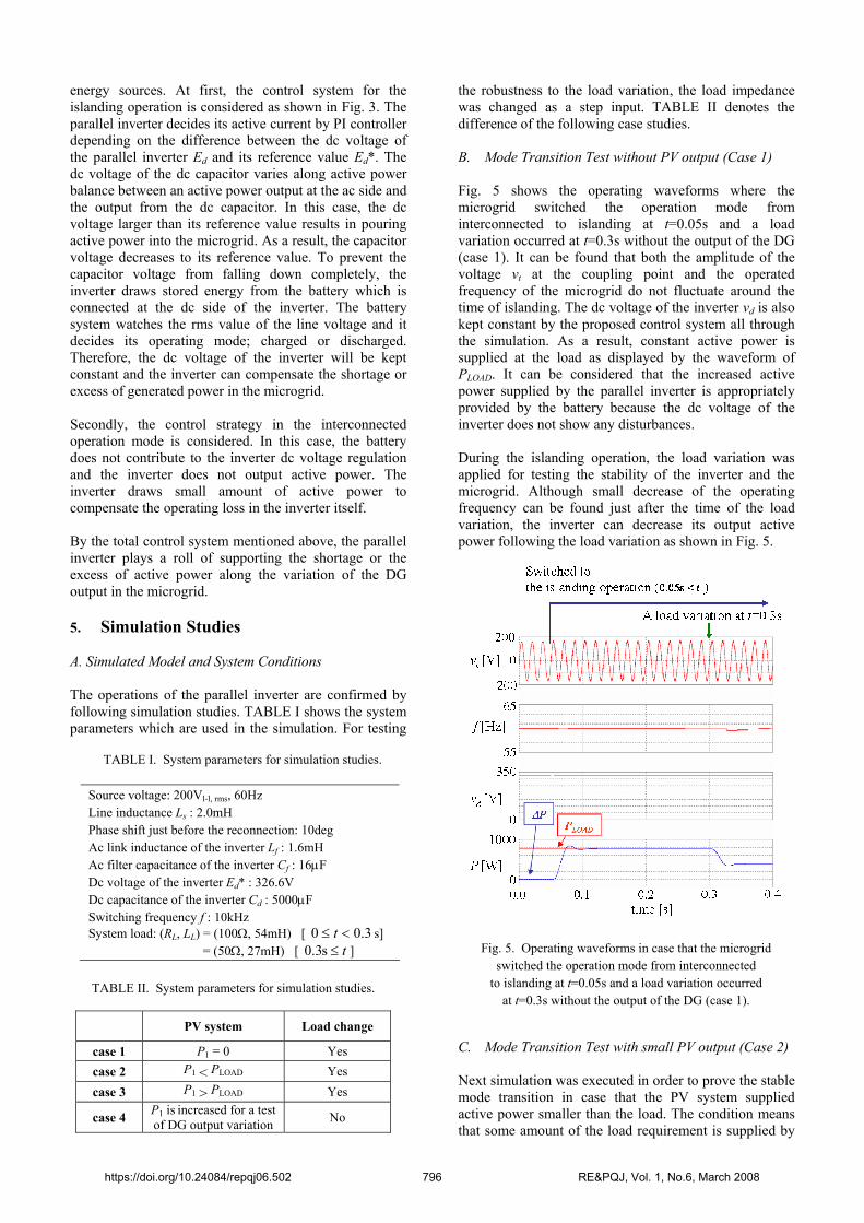
TABLE I. System parameters for simulation studies.
Source voltage: 200Vl-l, rms, 60Hz Line inductance Ls : 2.0mH Phase shift just before the reconnection: 10deg Ac link inductance of the inverter Lf : 1.6mH Ac filter capacitance of the inverter Cf : 16µF Dc voltage of the inverter Ed* : 326.6V Dc capacitance of the inverter Cd : 5000µF Switching frequency f : 10kHz System load: (RL, LL) = (100Ω, 54mH) [ 3.00 <≤ t s] = (50Ω, 27mH) [ t≤s3.0 ]
TABLE II. System parameters for simulation studies.
PV system Load change
case 1 P1 = 0 Yes case 2 P1 < PLOAD Yes case 3 P1 > PLOAD Yes
case 4 P1 is increased for a test of DG output variation No
Fig. 5. Operating waveforms in case that the microgrid
switched the operation mode from interconnected to islanding at t=0.05s and a load variation occurred
at t=0.3s without the output of the DG (case 1).
energy sources. At first, the control system for the islanding operation is considered as shown in Fig. 3. The parallel inverter decides its active current by PI controller depending on the difference between the dc voltage of the parallel inverter Ed and its reference value Ed*. The dc voltage of the dc capacitor varies along active power balance between an active power output at the ac side and the output from the dc capacitor. In this case, the dc voltage larger than its reference value results in pouring active power into the microgrid. As a result, the capacitor voltage decreases to its reference value. To prevent the capacitor voltage from falling down completely, the inverter draws stored energy from the battery which is connected at the dc side of the inverter. The battery system watches the rms value of the line voltage and it decides its operating mode; charged or discharged. Therefore, the dc voltage of the inverter will be kept constant and the inverter can compensate the shortage or excess of generated power in the microgrid. Secondly, the control strategy in the interconnected operation mode is considered. In this case, the battery does not contribute to the inverter dc voltage regulation and the inverter does not output active power. The inverter draws small amount of active power to compensate the operating loss in the inverter itself. By the total control system mentioned above, the parallel inverter plays a roll of supporting the shortage or the excess of active power along the variation of the DG output in the microgrid. 5. Simulation Studies A. Simulated Model and System Conditions The operations of the parallel inverter are confirmed by following simulation studies. TABLE I shows the system parameters which are used in the simulation. For testing
the robustness to the load variation, the load impedance was changed as a step input. TABLE II denotes the difference of the following case studies. B. Mode Transition Test without PV output (Case 1) Fig. 5 shows the operating waveforms where the microgrid switched the operation mode from interconnected to islanding at t=0.05s and a load variation occurred at t=0.3s without the output of the DG (case 1). It can be found that both the amplitude of the voltage vt at the coupling point and the operated frequency of the microgrid do not fluctuate around the time of islanding. The dc voltage of the inverter vd is also kept constant by the proposed control system all through the simulation. As a result, constant active power is supplied at the load as displayed by the waveform of PLOAD. It can be considered that the increased active power supplied by the parallel inverter is appropriately provided by the battery because the dc voltage of the inverter does not show any disturbances. During the islanding operation, the load variation was applied for testing the stability of the inverter and the microgrid. Although small decrease of the operating frequency can be found just after the time of the load variation, the inverter can decrease its output active power following the load variation as shown in Fig. 5.
C. Mode Transition Test with small PV output (Case 2) Next simulation was executed in order to prove the stable mode transition in case that the PV system supplied active power smaller than the load. The condition means that some amount of the load requirement is supplied by
https://doi.org/10.24084/repqj06.502 796 RE&PQJ, Vol. 1, No.6, March 2008

Fig. 6. Operating waveforms in case that the microgrid
switched the operation mode from interconnected to islanding at t=0.05s and a load variation occurred at t=0.3s with the small output of the DG (case 2).
Fig. 7. Operating waveforms in case that the microgrid
switched the operation mode from interconnected to islanding at t=0.05s and a load variation occurred at t=0.3s with the large output of the DG (case 3).
Fig. 8. Operating waveforms in the test of long term
operation (Case 4).
the PV system but the rest must be provided by the parallel inverter during the islanding mode. The operating waveforms are displayed in Fig. 6. During the interconnected operation, the parallel inverter does not supply active power. In this case, 600W is supplied by the conventional power grid and 200W is provided by the PV system. In the islanding mode, the active power is supplied by the parallel inverter as shown in Fig. 6. Any disturbance cannot be found in this operation, too. The inverter can also work well at the load variation. D. Mode Transition Test with large PV output (Case 3) This case study is similar except that the PV output is larger than the previous study as shown in Fig. 7. In this case, the parallel inverter absorbs the surplus active power and charging the battery. 2kW active power is supplied by the PV system, and 800W of the power is consumed at the load and the rest of 1.2kW is used to charge the battery at the parallel inverter. The microgrid also shows stable operation in this case 3. E. Long Term Operation Test (Case 4) Fig 8 shows the results of long term operation test. In this test, the first mode transition is assumed at t =0.05s, which changes the mode from the interconnected to the islanding operation. The second transition is at t=1.08s, which is a transition from the islanding to the interconnected operation. This transition is applied after the phase shifting of voltage at the coupling point by the parallel inverter, which is explained in Fig. 4, in order to achieve smooth re-interconnection with the grid. In the simulated duration, the quality of the terminal voltage is almost kept constant as shown in Fig. 8. The PV output
varies as displayed by the waveform of P1, but the supplied power to the load is compensated by the parallel inverter output ∆P. After the re-interconnection at t=1.08s, battery charging current flows into the parallel inverter as depicted by the waveforms is and ∆P. There are not inrush current and unstable phenomena caused by the mode transition or disturbances.
https://doi.org/10.24084/repqj06.502 797 RE&PQJ, Vol. 1, No.6, March 2008

6. Conclusions This paper deals with a control method of the parallel inverter for islanding operation of a microgrid. It is confirmed that the parallel inverter can successfully support the islanding operation of the microgrid with a PV system and impedance load. The parallel inverter shows good performance in the simulation studies, even if the load or PV output variation is applied. Moreover, it can connect the microgrid to the conventional power grid when some phase shift is assumed at the time of re-connection. In addition to this as the future work, operating characteristics of the parallel inverter and total system stability will be carefully investigated in case that a distributed generator by a rotating DG is employed in the islanding microgrid. With an appropriate stabilizing control like the one that the author has proposed previously in the Reference [6], the microgrid can stand under the islanding operation.
References [1] S. Morozumi, “Micro-grid demonstration projects in
Japan,” PCC Nagoya, 2007. [2] R.H. Lasseter, “Microgrids,” IEEE Power Engineering
Society Winter Meeting, 2001, Vol. 1, pp. 146-149, 2001. [3] T. Yabe, Y. Zoka, N. Yorino and T. Doi, “An examination
for unstable phenomenon of autonomous small independent network of distributed generators in islanding condition,” The papers of joint technical meeting on power engineering and power systems engineering, IEE Japan, PE-06-88, PSE-06-88, 2006 (in Japanese).
[4] A. Nakamaru, Y. Shirai, T. Nitta, T. Yamashita, K. Shibata, “Transition to the independent system operators by use of Superconducting Magnet Energy Storage,” The papers of joint technical meeting on power engineering and power systems engineering, IEE Japan, PE-03-25, PSE-03-36, 2003 (in Japanese).
[5] A. Emadi, A. Nasiri and S.B. Bekiarov, Uninterruptible power supplies and active filters, CRC Press, Boca Raton (2005).
[6] M. Hojo, Y. Mitani and K. Tsuji, “Linearization of generator power swing property by controlling power output of SMES for enhancement of power system stability,” IEEE Trans. on Applied Superconductivity, Vol. 9, No. 2, 1999.
https://doi.org/10.24084/repqj06.502 798 RE&PQJ, Vol. 1, No.6, March 2008