A computer-based model for gas-turbine power augmentation ...
16
STROJN ´ ICKY ˇ CASOPIS, 59, 2008, ˇ c. 4 189 A computer-based model for gas-turbine power augmentation by inlet-air cooling and water/steam injection MOHAMED M. EL-AWAD The paper presents a computer-based thermodynamic model that esti- mates the effects of power augmentation methods on the gas turbine power and heat rate. The model takes into consideration the effect of evaporative or refrigerative inlet-air cooling and allows for water or steam injection into the combustion chamber. The formulation of the model improves upon the conventional “standard-air” analysis by including the effects of water on the working-fluid properties, by accounting for the mass of fuel, and by adopting the exact variable specific-heat approach. The model also improves the ac- curacy and extends the scope of the analysis by solving an energy equation for the combustion process, which enables either the combustion temperature, or the required rate of fuel consumption, to be specified and the other to be calculated. The paper describes the thermodynamic model and the computer program based on it. Verification of the computer-based model against relevant published data is also presented and discussed. K e y w o r d s: power generation, gas turbine, inlet-air cooling, power aumenta- tion, computer model 1. Introduction Gas turbines have become the favoured power generation machines in many parts of the world. Standing alone in open-cycle, gas turbines are used to meet the peak-loads and combined with steam turbines in combined cycles they are used as efficient base-load machines. The easy-to-start capability, fuel-flexibility, low-fuel cost, and low environmental pollution offer the gas-turbine clear advan- tages over other power-generation machines. Unfortunately, the performance of these machines is greatly degraded by adverse ambient conditions due to the high air temperatures and dusty environment. Being a constant volume-flow machine, Mechanical Engineering Department, Faculty of Engineering & Architecture, Univer- sity of Khartoum, P. O. Box 321, Khartoum, Sudan e-mail address: [email protected]
Transcript of A computer-based model for gas-turbine power augmentation ...

STROJNICKY CASOPIS, 59, 2008, c. 4 189
A computer-based model for gas-turbine poweraugmentation by inlet-air cooling
and water/steam injection
MOHAMED M. EL-AWAD
The paper presents a computer-based thermodynamic model that esti-mates the effects of power augmentation methods on the gas turbine powerand heat rate. The model takes into consideration the effect of evaporativeor refrigerative inlet-air cooling and allows for water or steam injection intothe combustion chamber. The formulation of the model improves upon theconventional “standard-air” analysis by including the effects of water on theworking-fluid properties, by accounting for the mass of fuel, and by adoptingthe exact variable specific-heat approach. The model also improves the ac-curacy and extends the scope of the analysis by solving an energy equationfor the combustion process, which enables either the combustion temperature,or the required rate of fuel consumption, to be specified and the other to becalculated. The paper describes the thermodynamic model and the computerprogram based on it. Verification of the computer-based model against relevantpublished data is also presented and discussed.
K e y w o r d s: power generation, gas turbine, inlet-air cooling, power aumenta-tion, computer model
1. Introduction
Gas turbines have become the favoured power generation machines in manyparts of the world. Standing alone in open-cycle, gas turbines are used to meetthe peak-loads and combined with steam turbines in combined cycles they areused as efficient base-load machines. The easy-to-start capability, fuel-flexibility,low-fuel cost, and low environmental pollution offer the gas-turbine clear advan-tages over other power-generation machines. Unfortunately, the performance ofthese machines is greatly degraded by adverse ambient conditions due to the highair temperatures and dusty environment. Being a constant volume-flow machine,
Mechanical Engineering Department, Faculty of Engineering & Architecture, Univer-sity of Khartoum, P. O. Box 321, Khartoum, Sudane-mail address: [email protected]

190 STROJNICKY CASOPIS, 59, 2008, c. 4
the power of the gas turbine is directly proportional to the mass flow rate of airthrough the turbine. A high ambient temperature (or humidity) reduces the airdensity and, accordingly, the mass-flow rate through the gas turbine. Therefore,the turbines loose significant portions of their design generation capacity at stan-dard ISO condition (15 ◦C) when operating in hot and humid climate. The gasturbines output typically decreases by 10 % to 18 % for every 10 K of increase ininlet air temperature [1, 2]. A high ambient temperature also increases their heatrate and, according to McCracken [2], gas turbines produce 25–35% less power insummer than in winter at 5–10 % higher heat rate, which means an average increaseof 6 % in fuel consumption.
Power producers apply various power augmentation methods in order to com-pensate for the effect of high temperatures on the gas-turbine output [2–7]. Thesemethods include refrigerative or evaporative inlet-air cooling. The refrigerativecooling can be of the mechanical or the absorption type and can be applied withor without thermal energy storage [3–5]. The evaporative cooling can be achievedby a conventional media-type method or by fogging [6, 7]. By applying inlet-aircooling, additional megawatts can be obtained from existing gas turbines at a frac-tion of the cost of installing new generation plants. According to Boyce [8], a newpower plant costs 500 $ per kilowatt while inlet air-cooling costs 110–120 $ perkilowatt of augmented power. Besides inlet-air cooling, power-augmentation canalso be achieved by injecting water or steam into the combustion chamber [9–11].Unfortunately, water injection, which is usually used for NOx control, increases theheat rate of the plant and, therefore, the generation cost [11]. The problem canbe solved by injecting steam, rather than liquid water. Since the flue gases areusually exhausted at a temperature exceeding 500 ◦C, the generation of steam in aheat-recovery steam generator enables some of this lost energy to be recovered andthe plant efficiency to be improved.
The required initial investments and running costs of the different power aug-mentation systems vary considerably [1, 8]. The suitability and economical fea-sibility of power augmentation methods depend strongly on the existing power--plant equipment and layout, the ambient atmospheric conditions, the effect of themethod on the turbine power and heat rate, and the electricity-consumption pat-tern. Therefore, a given power augmentation method may have certain advantagesor disadvantages, compared to other methods, when a particular gas-turbine powerplant is considered. The present work is part of an on-going effort to develop acomputer-based model that estimates the effect of the different power augmenta-tion methods on the turbine output. The model, which takes into considerationthe effect of inlet air cooling on the turbine power and heat rate and allows forwater or steam injection into the combustion chamber, can assist in the selectionof the suitable power augmentation method. Sections 2 and 3 of this paper describethe analytical thermodynamic model and the computer program based on it whileSection 4 deals with the model verification against published data.
STROJNICKY CASOPIS, 59, 2008, c. 4 191
2. The thermodynamic model
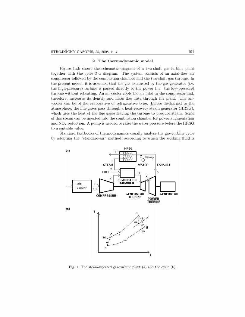
Figure 1a,b shows the schematic diagram of a two-shaft gas-turbine planttogether with the cycle T -s diagram. The system consists of an axial-flow aircompressor followed by the combustion chamber and the two-shaft gas turbine. Inthe present model, it is assumed that the gas exhausted by the gas-generator (i.e.the high-pressure) turbine is passed directly to the power (i.e. the low-pressure)turbine without reheating. An air-cooler cools the air inlet to the compressor and,therefore, increases its density and mass flow rate through the plant. The air--cooler can be of the evaporative or refrigerative type. Before discharged to theatmosphere, the flue gases pass through a heat-recovery steam generator (HRSG),which uses the heat of the flue gases leaving the turbine to produce steam. Someof this steam can be injected into the combustion chamber for power augmentationand NOx reduction. A pump is needed to raise the water pressure before the HRSGto a suitable value.
Standard textbooks of thermodynamics usually analyse the gas-turbine cycleby adopting the “standard-air” method, according to which the working fluid is
Fig. 1. The steam-injected gas-turbine plant (a) and the cycle (b).
192 STROJNICKY CASOPIS, 59, 2008, c. 4
treated as pure air whose specific heats are evaluated at some average temperatureor even kept constant at their room-temperature values [12, 13]. Moreover, theeffect of the fuel mass on the turbine work is completely ignored. These assumptionsallow an “approximate method” of analysis to be applied, which greatly simplifiesthe analysis. However, the results of the approximate method are known to deviatefrom the exact values by significant margins [13]. The present thermodynamicmodel includes the effects of water on the working-fluid properties, adopts the exactvariable specific-heat approach [13] and accounts for the fuel mass. By solving anenergy equation for the combustion process, the model extends the analysis scopesince this enables either the combustion temperature or the required rate of fuelconsumption to be specified and the other calculated. In order to simplify themodel, pressure and heat losses are ignored anywhere in the cycle.
2.1 T h e a i r c o m p r e s s o r
Given the inlet-air temperature (T1) and humidity (ω1), the enthalpy of humidair (per kg of dry air) at the compressor inlet (h1) is determined from:
h1 = h1da + ω1h1w, (1a)
where h1da and h1w are the specific enthalpies of dry air and water-vapour, re-spectively. The enthalpy of humid air after an ideal isentropic compression (h2s)is determined using the compressor pressure ratio (Prc) and the relative pressure(Pr) as follows [12]:
T1 → Pr1; Pr2 = Pr1 × Prc; Pr2 → T2s → h2s. (1b)
Note that an iterative method is needed to find T2s from Pr2 of the humid air. Theactual enthalpy after compression (h2) is calculated from the isentropic head asfollows:
h2 = h1 +h2s − h1
ηc, (1c)
where ηc is the compressor isentropic efficiency.The input of the compressor (Wc) is calculated from the mass flow rate and
air enthalpy increase within the compressor as follows:

STROJNICKY CASOPIS, 59, 2008, c. 4 193
mha = (1 + ω)mda; (1d)
Wc = mha(h2 − h1), (1e)
where (mha) and (mda) are the mass flow rates of humid air and dry air, respec-tively. The compressor discharge temperature (T2) is found from the dischargeenthalpy of humid air (h2) by iteration.
2.2 T h e c om b u s t i o n p r o c e s s
The presence of excess air into the combustion chamber, which is usuallythe case with gas turbines, assures complete combustion of the hydrocarbon fuel.Neglecting kinetic energy and potential energy changes between inlet and exit ofthe combustion chamber, the energy balance over an adiabatic chamber is givenby: (
1×H0f
)+
(nh2
)da
+(nh2
)w
+(nh8
)wi
=(nh3
)w
+(nh3
)wi
+(nh3
)H2O
+(nh3
)CO2
(2a)
+(nh3
)excess da
−(nh3
)O2
,
where H0f is the molar heat (enthalpy) of formation of the hydrocarbon gas-fuel, n
is the number of moles of the reactant or product of combustion per mole of the fuel,and h is the molar enthalpy. The suffices H2O and CO2 refer to the two productsof combustion (water and carbon dioxide) and O2 refers to oxygen. The sufficesda, w and wi refer to the dry air, air-borne moisture, and injected water/steam,respectively. Suffices 2 and 3 refer to the conditions (i.e. temperatures) beforeand after the combustion chamber. The number of oxygen-moles appearing in theproduct side is obtained from:
(n)O2 = (n)CO2 +12(n)H2O. (2b)
Equation (2) is used to find T3 when the fuel-air ratio is specified, or to findthe fuel-air ratio (mass of fuel per unit mass of dry air) when the combustiontemperature (T3) is specified.
2.3 T h e g a s - g e n e r a t o r t u r b i n e
The enthalpy after the gas-generator turbine (h4) is obtained by equating thegas-generator turbine work with the compressor work. The discharge temperature(T4) is then obtained from h4 by iteration:

194 STROJNICKY CASOPIS, 59, 2008, c. 4
h4 = h3 −Wc
mha; h4 → T4. (3a)
The enthalpy (h4s) and temperature (T4s) after an ideal, isentropic expansionare then obtained using the generator turbine efficiency (ηgt):
h4s = h3 −h3 − h4
ηgt; h4s → T4s. (3b)
The pressure at the outlet of the gas-generator turbine is determined from theknown temperatures T3 and T4s using the isentropic expansion relationship:
T3 → Pr3; T4s → Pr4; P4 = P3 ×Pr4
Pr3. (3c)
2.4 P ow e r t u r b i n e a n d t h e rm a l e f f i c i e n c y
Assuming the discharge pressure from the power turbine (P5) to be the sameas the inlet pressure P1, the enthalpy after an ideal, isentropic expansion (h5s) isdetermined from the known temperature (T4) and pressure ratio (P5/P4) as follows:
T4 → Pr4; Pr5 = Pr4 ×P5
P4; Pr5 → T5s → h5s. (4a)
The actual enthalpy at the outlet of the power turbine (h5) is then calculatedfrom the isentropic efficiency of the turbine (ηpt) and enthalpy difference (h4−h5s):
h5 = h4 − (h4 − h5s)× ηpt. (4b)
The net work of the gas turbine per unit mass flow rate of dry air is equal tothat of the power turbine (Wpt), which is calculated as follows:
Wpt = (mha + mfuel + mwi)(h4 − h5), (4c)
where mfuel is the fuel consumption and mwi is the rate of water/steam injectionper unit mass of dry air. The heat energy of the fuel (Qin) and thermal efficiency(ηth) are then obtained from:
Qin = mfuel × LHV ; (4d)

STROJNICKY CASOPIS, 59, 2008, c. 4 195
η =Wpt
Qin
, (4e)
where LHV is the fuel lower heating value. Finally, the exhaust-gas temperature(T5) is obtained from the calculated enthalpy (h5) of the gas mixture by iterationand the energy balance over the HRSG is given by:
(mha + mfuel + mwi)(h5 − h6) = mwi(h8 − h7). (5)
3. The computer program
A computer program has been developed based on the above thermodynamicmodel to analyse the gas-turbine cycle with power augmentation by inlet-air cool-ing and/or water/steam injection. Developed in FORTRAN, the program initiallyreads the basic data of the gas turbine (total pressure ratio, compressor and tur-bine efficiencies, combustion temperature, and rate of fuel injection) and requiresthe user to specify a reference atmospheric condition as described by the inlet val-ues of the pressure, temperature and humidity. It then asks the user about theactual inlet-air condition and the method of power augmentation to be consid-ered. If inlet-air cooling is to be used, the program determines the dew-point andwet-pulp temperatures and informs the user with their values since these two tem-peratures determine the limiting values for refrigerative and evaporative cooling,respectively. If water/steam is to be injected, the program asks about the tem-perature of water/steam to be injected in order to calculate the maximum rate ofinjection that saturates the air at the compressor discharge. It then asks the userto give the required rate of water/steam injection, which should be less than themaximum value, before proceeding to calculate, from the relationships describedin the preceding section, the compressor work, combustion temperature (or fuelrate), gas-generator turbine work and exit pressure, power turbine work and exittemperature, and thermal efficiency of the plant. The important details of thecomputer program are given below.
3.1 T h e r e f e r e n c e a t m o s p h e r i c c o n d i t i o na n d r e f e r e n c e v o l u m e f l o w r a t e
The mass flow rate through the gas turbine at a particular site depends onthe air density, which depends on the atmospheric pressure, ambient temperature,and humidity. To be able to compare the gas-turbine performance at differentatmospheric or inlet-air conditions, the present computer model analyses the cycleon the basis of volume flow rate rather than mass flow rate. A reference volume flowrate (VR ) is defined as the volume that contains a unit mass flow rate (1 kg · s−1) ofdry air at a chosen “reference” inlet-air condition. The reference inlet-air conditioncan be the design condition or the ISO standard condition of 101.325 kPa, 15 ◦C,

196 STROJNICKY CASOPIS, 59, 2008, c. 4
and 60 % humidity. But it can also be a certain atmospheric conditions at the gas-turbine site, say in a winter day. At atmospheric or inlet-air conditions which aredifferent from the reference condition, the reference volume will contain differentmass flow rates of dry air and moisture. Applying thermodynamic relations for amixture of two ideal gases (dry air and water-vapour), the reference volume flowrate is given by [12]:
VR =RaTR
PR,da=
RaTR
−φRPsat
100
, (6)
where Ra is the gas constant for dry air. TR, PR, φR, and PR,da are, respectively,values of the pressure, temperature, relative humidity (%), and partial pressureof dry air at the reference atmospheric condition. Psat is the saturation pressurefor water at the reference temperature. The total mass flow rate of humid air(dry air + moisture) entering the compressor through the reference volume at thereference condition is equal to (1+ωR) kg · s−1, where ωR is the absolute humidity(or humidity ratio) of air at the reference condition.
3.2 A c t u a l m a s s f l ow r a t e o f a i r t h r o u g h t h e c o m p r e s s o r
At atmospheric condition other than the reference condition, the total massflow rate of dry air through the reference volume is calculated from the given valuesof atmospheric pressure (Patm) and dry-bulb temperature (Tatm) as follows:
mda =Pda
RaTatmVR. (7a)
Using Eq. (6), this becomes:
mda =PdaTR
PR,daTatm. (7b)
The total mass flow rate of humid air (mha) is then given by:
mha = (1 + ωatm)mda. (7c)
The specific humidity at actual atmospheric condition (ωatm) is eithergiven or determined from the relative humidity (φatm) according to the knownthermodynamic relations for a mixture of air-water vapour mixture [12].
3.3 E f f e c t o f w a t e r / s t e a m i n j e c t i o no n t h e c o m bu s t i o n t e m p e r a t u r e
The injection of liquid water or steam into the combustion chamber causesthe combustion temperature to drop unless more fuel is added. Two options havebeen considered and included in the program:

STROJNICKY CASOPIS, 59, 2008, c. 4 197
1. to maintain the combustion temperature at its value prior to water/steaminjection,
2. to keep the fuel consumption constant and allow the combustion tempera-ture to drop.
The amount of additional fuel required to maintain the combustion tempera-ture equal to that prior to water/steam injection depends on the temperature andinjection rate of water/steam. More fuel is consumed when the injection rate ofwater/steam increases and/or when its temperature decreases. The required fuelflow rate is obtained from the energy equation (Eq. 2). If no fuel is supplied inaddition to that prior to water/steam injection and the combustion temperature isallowed to drop, Eq. (2) is solved to give the new combustion temperature. In thiscase, the work from air and the combustion products will be reduced as a resultof the reduced temperature and enthalpy at the turbine inlet. However, additionalwork is provided by the injected water/steam, which increases the mass flow ratein the turbine. Therefore, both the turbine power output and thermal efficiencydepend on the additional work of the injected steam or water.
3.4 M od e l l i n g t h e w o r k i n g f l u i d
The thermodynamic model described above requires values of the enthalpy(h) and relative pressure (Pr) for the working fluid, which consists of two gases ormore. The computer program evaluates the required thermodynamic propertiesby treating the pre-combustion working fluid as a mixture of two ideal gases, viz.dry air and water vapour. After combustion the working fluid consists of thesetwo components plus the products of combustion (CO2, N2 and H2O). If the tem-perature is known, the thermodynamic properties of the pro-combustion workingfluid can also be found easily by treating it as a mixture of ideal gases. However,if an inverse solution is required (e.g. finding T from a known value of h) it willbe difficult to perform an iterative solution for more than two components (seesection 3.6 below). Therefore, the pro-combustion working fluid is also treated asa mixture of dry air and water vapour, but the program offers the user two optionsfor modelling the water vapour part:
1. Model 1: all products of combustion – including the combustion water –are treated as dry air. Thus, the water vapour part includes the original air-bornemoisture plus the water vapour that results from the injected water/steam.
2. Model 2: the combustion water is also included into the water vapourcomponent. Thus, the dry air component includes only CO2 and N2.
For the purpose of code verification and comparison with available data, theprogram offers a third option that treats all the working fluid as dry air. Thisoption, called Model 0, is similar to the air-equivalent method of Bathie [13], whoalso used variable specific heats but did not take into consideration the effect ofinlet-air humidity.

198 STROJNICKY CASOPIS, 59, 2008, c. 4
3.5 T h e rm o d y n am i c p r o p e r t i e s o f t h e w o r k i n g f l u i d
The computer program obtains the thermodynamic properties of the working--fluid components using various relations. Most of these relations were adoptedfrom the published literature [12, 13], but some relationships have been deriveddirectly from thermodynamic property tables. Properties of the dry air, watervapour, products of combustion, and liquid water are determined from the followingrelations:
Air :Treated as an ideal gas, the enthalpy of air depends on the temperature alone
and is obtained from the following relationship [12]:
h = Ra ×{
a× T +b
2× T 2 +
c
3× T 3 +
d
4× T 4
+e
5× T 5
}− 302.67, [kJ · kg−1], (8a)
where a, b, c, d, and e are constants and T is the absolute temperature in Kelvin.The constant −302.67 is added to the original equation given by Moran and Shapiro[12] in order to unify their reference temperature (originally taken as 0.0 K) withthat of Bathie [13], taken as 298.15 K or 25 ◦C.
The relative pressure is also obtained from a polynomial in temperature. Forthe temperature range 500–1000 K, this is given by the following 4th order poly-nomial:
Pr = a + b× T + c× T 2 + d× T 3 + e× T 4, [kJ · kg−1], (8b)
where the constants a, b, c, d, and e have the values of 8.2488968, −0.060512094,0.00016927346, −1.8744272 × 10⁻⁷ and 1.8445728 × 10⁻¹⁰, respectively. For tem-peratures higher than 1000 K, the 4th order polynomial requires a different set ofcoefficients. For temperatures lower than 500 K, a 10th order polynomial is useddue to the rapid change with temperature.
Water vapour and products of combustion:The enthalpies of the water vapour and products of combustion (CO2 and
O2), which also depend on the temperature alone, are obtained from the followingrelation [12]:
h = Ru × T ×{
a +b
2× T +
c
3× T 2 +
d
4× T 3 +
e
5× T 4 +
f
T
}, [kJ · kmol−1],
(9)

STROJNICKY CASOPIS, 59, 2008, c. 4 199
where Ru is the universal ideal gas constant and T is the absolute temperaturein Kelvin. The values of the constants a, b, c, d, e, and f are obtained by fittingpolynomials to the tabulated values of h for each gas/vapour. For a better accuracy,two sets of these constants are used depending on the temperature level, the levelsbeing 300–1000 K and 1000–5000 K. The model also requires the relative pressurefor the air-water vapour mixture. This is obtained by fitting 4th order polynomialsto the required data of the air and water vapour with different coefficients for threetemperature levels: less than 500 K, 500–1000 K and 1000–1500 K.
Liquid water :Two thermodynamic properties of liquid water are required in the model,
which are the enthalpy (h) and saturation pressure at a given temperature (Psat).The enthalpy of water at the injection temperature is approximated by that ofsaturated liquid at the given temperature (hf), which is obtained from the followingrelationship:
h ≈ hf = hsteam − hfg, [kJ · kg−1], (10a)
where hsteam is the value of enthalpy for water vapour as obtained from Eq. (9) andhfg is the latent heat of vaporisation [kJ · kg−1] at the given temperature obtainedfrom the following third-order polynomial:
hfg = a + b× T + c× T 2 + d× T 3, [kJ · kg−1], (10b)
in which T is in ◦C and values of the coefficients a, b, c, and d are obtained by fittinga polynomial to the tabulated values of hfg for water [12]. The respective values ofthese constants are 2501.3687, −2.3680605, 0.00056653491 and −1.3212214×10⁻⁵.The polynomial is applicable in the range of temperatures 5–100 ◦C.
The saturation pressure of water (Psat) at a given temperature is obtainedfrom the following relation [12]:
ln(Psat) = 70.4346943− 7362.6981T
+ 0.006952085T − 9.0ln(T ), (10c)
where T is in Kelvin and Psat is in atmospheres. The relationship is applicable fortemperatures in the range 0–200 ◦C.
3.6 T h e i t e r a t i v e s o l u t i o n p r o c e d u r e
In all the thermodynamic property relations given above, the properties arefunctions of the temperature. When the value of a given property (say h) is knownand the corresponding temperature is to be determined, an inverse solution of these

200 STROJNICKY CASOPIS, 59, 2008, c. 4
relations is required which the present computer program obtains by an iterativeprocedure. This iterative solution is particularly needed since the working fluidin the present model is a mixture of gases and not simply dry air. First, a valueof the temperature (Tguess) is assumed, which must be lower than the expectedtemperature (if a better guess cannot be made, this initial guess is made equalto 273 K, or 0 ◦C). The calculated value of the required property at the guessedtemperature (say hguess) is then compared with the known value of the property(hknown).
Since the thermodynamic properties increase with temperature, the calcu-lated property value will be lower than the required value. The temperature isthen increased by a reasonably large increment ∆T (typically 10 K) and hguess isrecalculated and compared with hknown. If hguess is still less than hknown, the tem-perature is increased again by ∆T . This is repeated until hguess exceeds hknown.Once this happens, the increment ∆T is reduced (typically by a factor of 10) andthe last step of the iterative solution is repeated using the smaller ∆T . The in-crement ∆T is reduced until a prescribed criterion ε = (hguess − hknown)/hknown
is met at which the value of Tguess is taken as the required solution for T . Asimilar iterative solution is applied when the rate of fuel combustion is fixed andthe combustion temperature is to be determined from the energy balance equation(Eq. 2).
4. Validation of the model
In order to verify the computer program with its property relationships, it wasinitially tested against the solutions given by Bathie [13] for the following two-shaftgas turbine:
Inlet air pressure = 101.35 kPaInlet air temperature = 15 ◦CInlet air humidity = 0.0 % (dry air)Compressor pressure ratio = 12 : 1Fuel = n-octane (C8H18)Fuel mass flow rate at rated load = 0.0214773 kg · kg−1 dry airFlue gas temperature at generator-turbine inlet (at rated load) = 1400 ◦CFlue gas temperature at power-turbine exit (at rated load) = 497.63 ◦CCompressor efficiency = 87 %Gas-generator and power turbines efficiency = 89%Bathie [13] analysed the cycle of the above gas turbine with and without steam
injection. Table 1 shows seven primary quantities in the cycle without steam in-jection as computed by the present computer model compared to their respectivevalues obtained from Bathie [13]. The table shows three solutions for the presentmodel (M0, M1 and M2), which represent the different options given by the com-puter program for modelling the working fluid as discussed in section 3.4. Bathie

STROJNICKY CASOPIS, 59, 2008, c. 4 201
T ab l e 1. Comparison of the main cycle parameters as computed by the present computerprogram with those given by Bathie [13]
Key Parameters Bathie [13] Present modelSA AE AF M0 M1 M2
Compressor work [kJ · kg−1] 343.0 343.0 343.0 344.78 344.79 344.79
T2 [K] 623.0 623.0 623.0 622.92 622.90 622.90
T4 [K] 1109.0 1115.8 1122.2 1114.50 1114.50 1123.70
P4 [kPa] 408.2 418.5 422.8 419.50 419.49 432.85
T5 [K] 815.0 815.0 831.1 814.31 814.30 818.67
Power turbine work [kJ · kg−1] 333.0 347.5 355.6 346.14 346.15 362.69
Thermal efficiency [%] 37.7 36.4 37.2 36.30 36.30 38.03
[13] also gave three solutions using standard-air (SA), air-equivalent (AE) and ac-tual fluid (AF) assumptions. As the table shows, the values of the two parametersprior to combustion (the compressor work and T2) as obtained by the present modelare close to one another and agree well with the three solutions given by Bathie[13] who also used variable specific heats but did not take into consideration theeffect of air humidity. Therefore, the present agreement between all six solutionsfor the first two parameters is anticipated since the inlet air humidity is zero andthe inlet air is assumed to be dry.
The different solution methods gave different solutions for the five parametersafter combustion. The figures on the table show that both Model 0 (air-equivalentoption) and Model 1 of the present model yield values for the five parameters,which are close to the air-equivalent (AE) solution given by Bathie [13]. Theagreement between Model 0 and the AE solution of Bathie [13] is anticipated butthe agreement with Model 1 is again due to the assumption used in the above casewith zero inlet air humidity. It should be expected that, for the general case ofhumid inlet air, the results obtained by Model 0 and Model 1 will be different.The values obtained by Model 2 are significantly different from those of Models 0and 1, giving higher values for T4, P4, T5, the power turbine work and the thermalefficiency. This option is closest to the actual fuel (AF) solution of Bathie [13].Also, note the difference between the standard air analysis (SA) of Bathie [13] andall other solutions.
Bathie [13] analysed the gas turbine cycle with steam injection at a tempera-ture of 380 ◦C and a rate of 2.5 % to that of the dry air flow. For a dry air mass-flowrate of 1 kg · s−1, his values for the power and thermal efficiency were 375.4 kW and37.5%, respectively. The corresponding values obtained by Model 1 of the presentmodel, which is similar to his AE method, are 377.2 kW and 37.7 %. The valuesobtained by the present Model 2 for the power and thermal efficiency are 394.6 kWand 39.4 %, respectively.
Figure 2a,b compares the model estimation for the power and heat rate of thegas turbine at different inlet-air temperatures with other estimates obtained from

202 STROJNICKY CASOPIS, 59, 2008, c. 4
Fig. 2. Effect of ambient temperature on the performance of gas turbines: (a) power,(b) heat rate.
the literature [3, 7, 14]. Punwani [3] provided estimates for both industrial andaeroderivative gas turbines. As can be seen from the figure, the model estimate ofthe turbine power agrees well with those given by all three sources for industrialgas turbines. Although the model estimate for the heat rate is also comparableto the data of Punwani [3], it slightly underestimates that of the General ElectricPG6581B model [14] at high inlet air temperatures. Figure 2 clearly shows thatthe model is suitable for industrial gas turbines rather than aeroderivative ones.
Since the effect of inlet-air humidity on the turbine power and heat rate is lesssignificant than that of air temperature, the “dry-air” solutions shown on Fig. 2 arepractically useful for humid air as well as dry air conditions. Also, since the effectof inlet-air temperature on the turbine power is more significant than that on the

STROJNICKY CASOPIS, 59, 2008, c. 4 203
heat rate, an inlet-air cooling system will pay for itself by the increased megawattsmore than by the reduced fuel consumption of the gas turbine.
5. Conclusions
Verification of the present computer-based thermodynamic model against rel-evant published data shows that the model estimates for the selected key cycleparameters compare well with these data. The effect of inlet-air cooling and steaminjection on the power and heat rate of the gas turbine is also predicted accuratelyby the model. Therefore, the present model can be used to study the effect ofevaporative or refrigerative inlet air cooling and water/steam injection on the gasturbine cycle and to analyse the effect of different combinations of these poweraugmentation methods on the gas turbine performance. The model can also beextended to calculate the expected annual revenues that result from the increasedmegawatts and reduced fuel consumption from inlet air cooling and/or water/steaminjection.
Acknowledgements
The author acknowledges the contribution of Phoon H. Y., a former student of Uni-versiti Tenaga Nasional (UNITEN), Malaysia, to the initial development and verificationof the present computer model.
REFERENCES
[1] CORTES, C. R.—WILLEMS, D. F.: In: Proc. of POWER-GEN International Con-ference. Tulsa, PennWell Corporation 2003.
[2] MCCRACKEN, C. D.: ASHRAE J., 33, 1991, p. 12.[3] PUNWANI, D.: Energy-Tech Magazine, Dec 2003, p. 20 (see also internet:
http://www.energy-tech.com/)[4] HASNAIN, S. M.—ALAWAJI, S. H. —AL-IBRAHIM, A.—SMIAI, M. S.: Interna-
tional Journal of Energy Research, 23, 1999, p. 117.[5] YONG, V. Y.: In: Proc. of 7th annual POWER-GEN Asia 1999. Volume 1. Ed.:
Gose, R. Tulsa, PennWell Corporation 1999, p. 187.[6] FARMER, R.: Gas Turbine World. March-April issue, 1999, p. 35.[7] Premier Industries, Inc., 2006, http://www.ctiac.com/turbine1.htm.[8] BOYCE, M. P.: A seminar held at Tenaga National Research & Development Centre
(TNRD), Malaysia 1999.[9] RICE, I. G.: ASME Transactions, Journal of Engineering for Gas Turbines and
Power, 117, 1995, p. 347.[10] TUZSON, J.: ASME Transactions, Journal of Engineering for Gas Turbines and
Power, 114, 1992, p. 682.[11] BROOKS, F. J.: GE Gas Turbine Performance Characteristics. GE Power Systems,
Schenectady, NY, GER-3567H, 2008.http://www.gepower.com/prod serv/products/tech docs/en/downloads/ger3567h.pdf

204 STROJNICKY CASOPIS, 59, 2008, c. 4
[12] MORAN, M. J.—SHAPIRO, H. N.: Fundamentals of Engineering Thermodynamics.5th edition. New York, John Wiley & Sons 2004.
[13] BATHIE, W. W.: Fundamentals of Gas Turbines. 2th edition. New York, John Wiley& Sons 1996.
[14] Garri Power Station Manuals. Private communication.
Received: 12.3.2007Revised: 23.9.2008