A Computational Model for Bending Fatigue Analyses of ...
7
*Corr. Author’s Address: University of Maribor, Faculty of Mechanical Engineering, Smetanova 17, 2000 Maribor, Slovenia, [email protected] 649 Strojniški vestnik - Journal of Mechanical Engineering 60(2014)10, 649-655 Received for review: 2014-03-04 © 2014 Journal of Mechanical Engineering. All rights reserved. Received revised form: 2014-04-30 DOI:10.5545/sv-jme.2014.1791 Original Scientific Paper Accepted for publication: 2014-05-16 0 INTRODUCTION Powder metallurgy (P/M) is useful in making parts that have irregular curves, or that are difficult to machine. It is suitable for high volume production with very little wastage of material. Powder metal gears were initially used only for light-duty applications, such as toys and power tools. Today, powder metal gears are a cost-efficient alternative for machined gears in larger series in the automotive industry (synchronizer gears, oil pump gears, engine gears, etc.). The next step should be power transmission gears [1]. A critical review regarding the application of P/M-sintered gears for transmissions and machinery was presented by Dizdar [2], who asserted that P/M- sintered gears can reach relatively high levels of dynamic strength when compared to wrought steel gears. They also offer highly sustainable production, low cost and full recycling for a range of applications in the automotive, power tool and home appliance industries. In recent years, high-performance sintered steel gears have been extensively investigated by researchers, specifically with regards to some new technologies (surface densification, gear rolling, burnishing, shot peening, high density pressing, warm compaction, warm die pressing techniques, etc.) and their influence on gear characteristics [3] to [5]. The research work presented in this paper is focused on the fatigue failures of sintered gears. Although two kinds of fatigue failures (surface pitting and tooth breakage) should be taken into account when dimensioning gear drives, only the tooth breakage [6] and [7] is addressed in this paper. ISO 6336, the classic standardised procedure [8], is usually used to determine the bending load capacity of treated gear pairs; however, it does not apply to gears finished by sintering. Some guidelines on how to calculate the bending load capacity of sintered external spur gears are described in the AGMA 930-A05 information sheet [9], although the required fatigue strength properties are not included in this sheet and should be taken from the available literature or determined experimentally. There is also a complicated geometrical analysis to determine the geometry factor for bending strength, which is usually quite impractical when calculating sintered gear pairs. In this paper, the stress-life approach is used to determine the fatigue life of sintered gears in regard to the bending stress in a gear tooth root. Because the stress field in the critical cross section in a gear tooth root is determined numerically using the FEM method, the proposed computational model can be applied to a wide range of gear pairs and is not limited by some geometrical parameters, as with the ISO [8] and AGMA [9] standards. 1 BENDING FATIGUE ANALYSIS USING STRESS LIFE APPROACH The stress-life (S-N) approach is usually used to determine the fatigue life of dynamically loaded machine parts, when stresses and strains are mostly elastic. This approach is based on the following Basquin equation: N a b f b = ⋅ σ σ 2 1 ' , (1) where N is the number of stress cycles to failure, σ a is the alternating stress, σ f ' is the fatigue strength A Computational Model for Bending Fatigue Analyses of Sintered Gears Glodež, S. – Šori, M. – Verlak, T. Srečko Glodež 1,* – Marko Šori 2 – Tomaž Verlak 1 1 University of Maribor, Faculty of Mechanical Engineering, Slovenia 2 University of Maribor, Faculty of Natural Science and Mathematics, Slovenia A computational model for determination of the fatigue life of sintered gears in regard to bending fatigue in a gear tooth root is presented. The proposed model is based on the stress-life approach in which the multi-axial state of stress, the mean stress effect, the influence of surface roughness, and the notch effect are studied when determining the fatigue life of a treated gear pair. The required material parameters (the fatigue strength coefficient σ f ' and the fatigue strength exponent b) are determined experimentally on a uni-axial tension/compression test machine with a load ratio of R = 0. Here, the influence of additional thermal treatment (after sintering) on the fatigue strength is studied. The model is used for the determination of the fatigue life of real spur gear made from a Höganäs Distaloy AB powder mixture, while the stress field in a gear tooth root is determined numerically using the FEM method. Keywords: sintered gears, fatigue, stress life approach, numerical modelling, experiments
Transcript of A Computational Model for Bending Fatigue Analyses of ...

*Corr. Author’s Address: University of Maribor, Faculty of Mechanical Engineering, Smetanova 17, 2000 Maribor, Slovenia, [email protected] 649
Strojniški vestnik - Journal of Mechanical Engineering 60(2014)10, 649-655 Received for review: 2014-03-04© 2014 Journal of Mechanical Engineering. All rights reserved. Received revised form: 2014-04-30DOI:10.5545/sv-jme.2014.1791 Original Scientific Paper Accepted for publication: 2014-05-16
0 INTRODUCTION
Powder metallurgy (P/M) is useful in making parts that have irregular curves, or that are difficult to machine. It is suitable for high volume production with very little wastage of material. Powder metal gears were initially used only for light-duty applications, such as toys and power tools. Today, powder metal gears are a cost-efficient alternative for machined gears in larger series in the automotive industry (synchronizer gears, oil pump gears, engine gears, etc.). The next step should be power transmission gears [1].
A critical review regarding the application of P/M-sintered gears for transmissions and machinery was presented by Dizdar [2], who asserted that P/M-sintered gears can reach relatively high levels of dynamic strength when compared to wrought steel gears. They also offer highly sustainable production, low cost and full recycling for a range of applications in the automotive, power tool and home appliance industries. In recent years, high-performance sintered steel gears have been extensively investigated by researchers, specifically with regards to some new technologies (surface densification, gear rolling, burnishing, shot peening, high density pressing, warm compaction, warm die pressing techniques, etc.) and their influence on gear characteristics [3] to [5].
The research work presented in this paper is focused on the fatigue failures of sintered gears. Although two kinds of fatigue failures (surface pitting and tooth breakage) should be taken into account when dimensioning gear drives, only the tooth breakage [6] and [7] is addressed in this paper. ISO 6336, the classic standardised procedure [8], is usually used to determine the bending load capacity of treated
gear pairs; however, it does not apply to gears finished by sintering. Some guidelines on how to calculate the bending load capacity of sintered external spur gears are described in the AGMA 930-A05 information sheet [9], although the required fatigue strength properties are not included in this sheet and should be taken from the available literature or determined experimentally. There is also a complicated geometrical analysis to determine the geometry factor for bending strength, which is usually quite impractical when calculating sintered gear pairs.
In this paper, the stress-life approach is used to determine the fatigue life of sintered gears in regard to the bending stress in a gear tooth root. Because the stress field in the critical cross section in a gear tooth root is determined numerically using the FEM method, the proposed computational model can be applied to a wide range of gear pairs and is not limited by some geometrical parameters, as with the ISO [8] and AGMA [9] standards.
1 BENDING FATIGUE ANALYSIS USING STRESS LIFE APPROACH
The stress-life (S-N) approach is usually used to determine the fatigue life of dynamically loaded machine parts, when stresses and strains are mostly elastic. This approach is based on the following Basquin equation:
N ab
f
b
=⋅
σσ2
1
', (1)
where N is the number of stress cycles to failure, σa is the alternating stress, σf' is the fatigue strength
A Computational Model for Bending Fatigue Analyses of Sintered Gears
Glodež, S. – Šori, M. – Verlak, T.Srečko Glodež1,* – Marko Šori2 – Tomaž Verlak1
1 University of Maribor, Faculty of Mechanical Engineering, Slovenia 2 University of Maribor, Faculty of Natural Science and Mathematics, Slovenia
A computational model for determination of the fatigue life of sintered gears in regard to bending fatigue in a gear tooth root is presented. The proposed model is based on the stress-life approach in which the multi-axial state of stress, the mean stress effect, the influence of surface roughness, and the notch effect are studied when determining the fatigue life of a treated gear pair. The required material parameters (the fatigue strength coefficient σf' and the fatigue strength exponent b) are determined experimentally on a uni-axial tension/compression test machine with a load ratio of R = 0. Here, the influence of additional thermal treatment (after sintering) on the fatigue strength is studied. The model is used for the determination of the fatigue life of real spur gear made from a Höganäs Distaloy AB powder mixture, while the stress field in a gear tooth root is determined numerically using the FEM method.Keywords: sintered gears, fatigue, stress life approach, numerical modelling, experiments

Strojniški vestnik - Journal of Mechanical Engineering 60(2014)10, 649-655
650 Glodež, S. – Šori, M. – Verlak, T.
coefficient and b is the fatigue strength exponent. The material parameters σf' and b can be determined experimentally, usually by means of a rotating bending test under fully reversed uniaxial stressing (stress ratio R = −1). If this is not the case, the influence of mean stress and a multi-axial state of stress should be considered when determining the appropriate alternating stress σa in Eq. (1). In this paper, the material parameters σf’ and b have been determined with a uni-axial pulsating test machine under a stress ratio of R = 0 (see Section 3). Because the stress ratio of R = 0 corresponds to the operation of real gear pairs, the mean stress effect can be omitted in this case. Otherwise, the effect of multi-axial stress in a gear tooth root should be considered using the Mises hypothesis [10]. Once the equivalent alternating stress σa,eq is determined on the basis of alternating principal stresses in a gear tooth root σa1, σa2 and σa3 (see Section 3), it should be considered when determining the fatigue life according to Eq. (1).
When determining the fatigue life of machine parts by using Eq. (1), the influence of the notch effect and the surface finish should also be considered, because the material parameters σf’ and b are usually determined using non-notched specimens with polished surfaces. If this is not the case, the appropriate notch factor Kf and surface factor Ks should be taken into account [11]. In the work presented in this paper, the test specimens used have been produced in the same way as actual sintered gears (compaction, sintering, additional thermal treatment, without additional polishing); see Section 2. Because the surface finish of the test specimens corresponds to the surface finish of real gears, the surface factor Ks = 1 can be assumed in such cases. The notch factor Kf is indirectly included in the alternating principal stresses σa1, σa2 and σa3, which are determined numerically in this study using the FEM method (see Section 3).
2 EXPERIMENTAL TESTING
The Automatic Die Compaction and Sintering (ADC/SINT) procedure has been used to prepare the test specimens. A base metal powder (iron) is mixed with alloying elements and lubricant. The alloying elements are added not only to improve material properties [12] and [13], but also to control dimensional change while sintering [14] and the final density of sintered component [15].
The powder mixture used in this study was Höganäs Distaloy AB with an addition of 0.58 wt% of Kenolube P11 and 0.3 wt% of carbon in the form of graphite UF4 (see Table 1). The powder mixture
had to be compressed into a desired shape. Before the compaction of specimens, the apparent density of the powder was 3.15 g/cm³ and the hall flow rate was 29 s per 50 g. Flat specimens (Fig. 1) were cold compacted at a compacting pressure of 485 MPa and then sintered for 30 minutes in a 10/90 hydrogen and nitrogen atmosphere at 1120 °C. After sintering, half of the specimens were subjected to the additional hardening (austenitization at 915 °C, oil-quenched and tempered for 1 h at 175 °C). Both sets of specimens had a final density of 7.07 g/cm³.
Fig. 1. Test specimen
Table 1. Chemical composition of used powder mixture and comparison with standardized powders according to DIN 30910-4 [16]
[wt%] Specimens SINT-D30 DIN 30910-4
Fe Bal Bal
C 0.29 < 0.3Cu 1.47 1.0 to 5.0Ni 1.69 1.0 to 5.0Mo 0.50 < 0.6
Kenolube 0.58
Additional grinding of specimens was done before experimental testing to remove the sharp edges that were a result of the compaction process and that could significantly affect the experimental results. However, the surface of the specimens was not additionally polished; therefore, surface roughness was measured at the locations and directions indicated in Fig. 2. Differences between both sets of specimens (with and without hardening) were negligible. Therefore, the average surface roughness of multiple measurements
Strojniški vestnik - Journal of Mechanical Engineering 60(2014)10, 649-655
651A Computational Model for Bending Fatigue Analyses of Sintered Gears
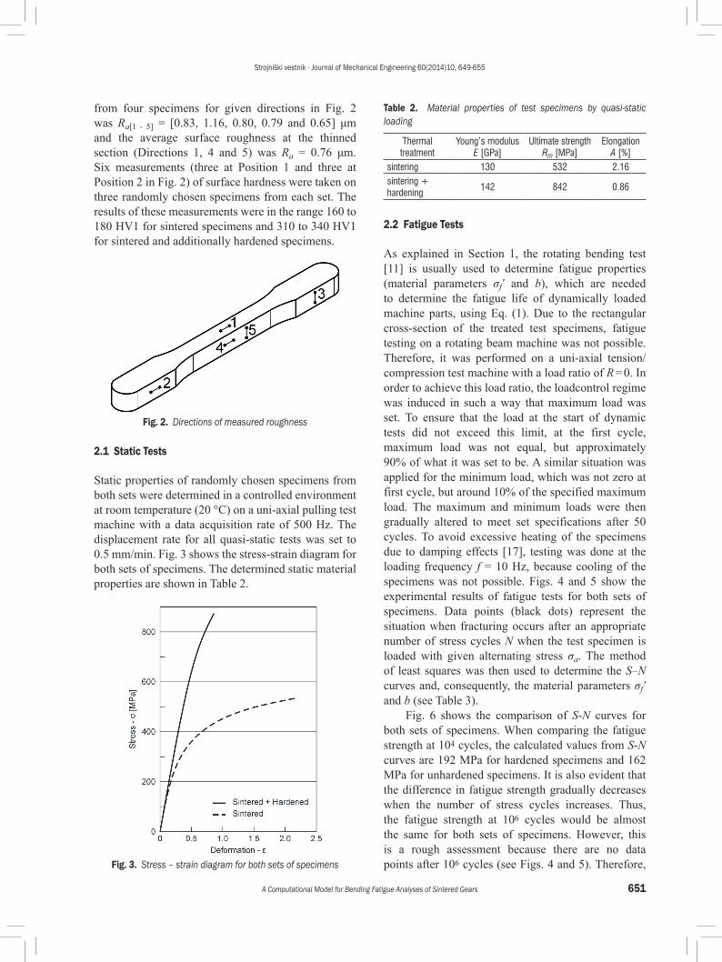
from four specimens for given directions in Fig. 2 was Ra[1 - 5] = [0.83, 1.16, 0.80, 0.79 and 0.65] μm and the average surface roughness at the thinned section (Directions 1, 4 and 5) was Ra = 0.76 μm. Six measurements (three at Position 1 and three at Position 2 in Fig. 2) of surface hardness were taken on three randomly chosen specimens from each set. The results of these measurements were in the range 160 to 180 HV1 for sintered specimens and 310 to 340 HV1 for sintered and additionally hardened specimens.
Fig. 2. Directions of measured roughness
2.1 Static Tests
Static properties of randomly chosen specimens from both sets were determined in a controlled environment at room temperature (20 °C) on a uni-axial pulling test machine with a data acquisition rate of 500 Hz. The displacement rate for all quasi-static tests was set to 0.5 mm/min. Fig. 3 shows the stress-strain diagram for both sets of specimens. The determined static material properties are shown in Table 2.
Fig. 3. Stress – strain diagram for both sets of specimens
Table 2. Material properties of test specimens by quasi-static loading
Thermal treatment
Young’s modulusE [GPa]
Ultimate strengthRm [MPa]
ElongationA [%]
sintering 130 532 2.16sintering + hardening
142 842 0.86
2.2 Fatigue Tests
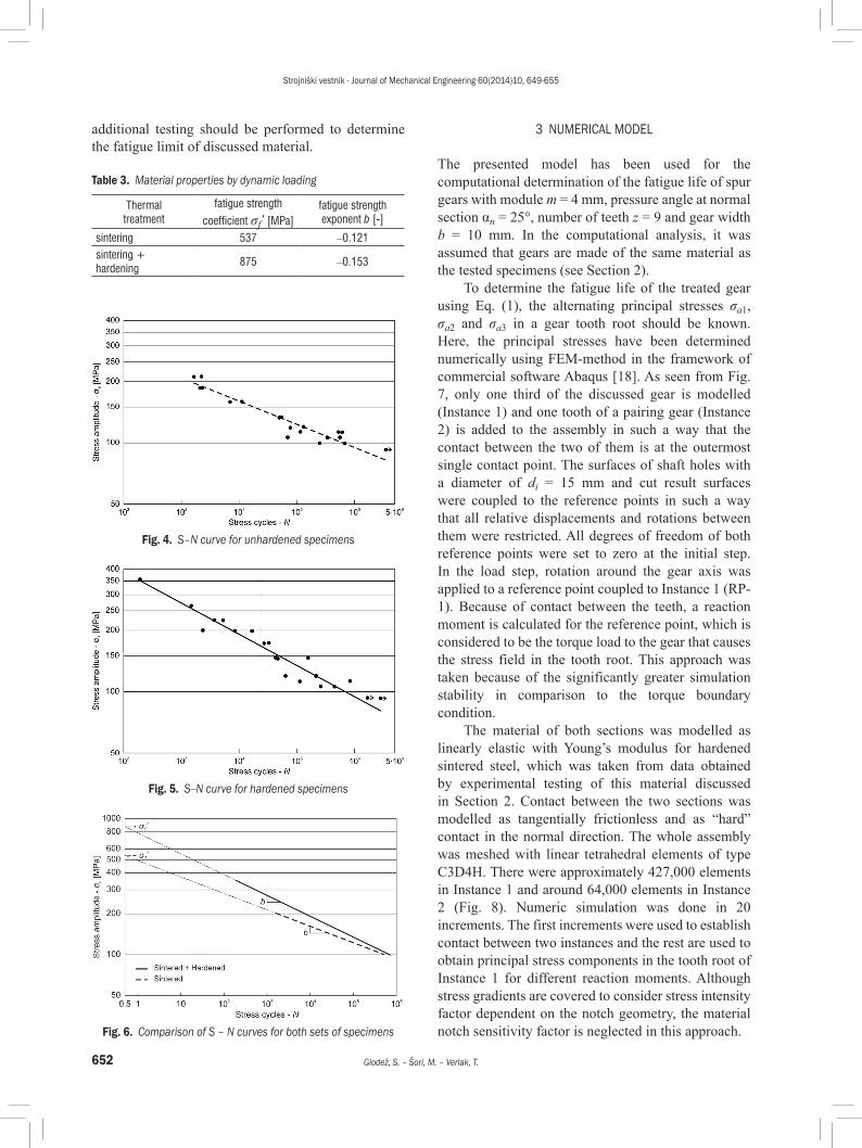
As explained in Section 1, the rotating bending test [11] is usually used to determine fatigue properties (material parameters σf’ and b), which are needed to determine the fatigue life of dynamically loaded machine parts, using Eq. (1). Due to the rectangular cross-section of the treated test specimens, fatigue testing on a rotating beam machine was not possible. Therefore, it was performed on a uni-axial tension/compression test machine with a load ratio of R = 0. In order to achieve this load ratio, the loadcontrol regime was induced in such a way that maximum load was set. To ensure that the load at the start of dynamic tests did not exceed this limit, at the first cycle, maximum load was not equal, but approximately 90% of what it was set to be. A similar situation was applied for the minimum load, which was not zero at first cycle, but around 10% of the specified maximum load. The maximum and minimum loads were then gradually altered to meet set specifications after 50 cycles. To avoid excessive heating of the specimens due to damping effects [17], testing was done at the loading frequency f = 10 Hz, because cooling of the specimens was not possible. Figs. 4 and 5 show the experimental results of fatigue tests for both sets of specimens. Data points (black dots) represent the situation when fracturing occurs after an appropriate number of stress cycles N when the test specimen is loaded with given alternating stress σa. The method of least squares was then used to determine the S–N curves and, consequently, the material parameters σf’ and b (see Table 3).
Fig. 6 shows the comparison of S-N curves for both sets of specimens. When comparing the fatigue strength at 104 cycles, the calculated values from S-N curves are 192 MPa for hardened specimens and 162 MPa for unhardened specimens. It is also evident that the difference in fatigue strength gradually decreases when the number of stress cycles increases. Thus, the fatigue strength at 106 cycles would be almost the same for both sets of specimens. However, this is a rough assessment because there are no data points after 106 cycles (see Figs. 4 and 5). Therefore,
Strojniški vestnik - Journal of Mechanical Engineering 60(2014)10, 649-655
652 Glodež, S. – Šori, M. – Verlak, T.
additional testing should be performed to determine the fatigue limit of discussed material.
Table 3. Material properties by dynamic loading
Thermaltreatment
fatigue strength
coefficient σf’ [MPa]fatigue strength exponent b [-]
sintering 537 –0.121sintering + hardening
875 –0.153
Fig. 4. S–N curve for unhardened specimens
Fig. 5. S–N curve for hardened specimens
Fig. 6. Comparison of S – N curves for both sets of specimens
3 NUMERICAL MODEL
The presented model has been used for the computational determination of the fatigue life of spur gears with module m = 4 mm, pressure angle at normal section αn = 25°, number of teeth z = 9 and gear width b = 10 mm. In the computational analysis, it was assumed that gears are made of the same material as the tested specimens (see Section 2).
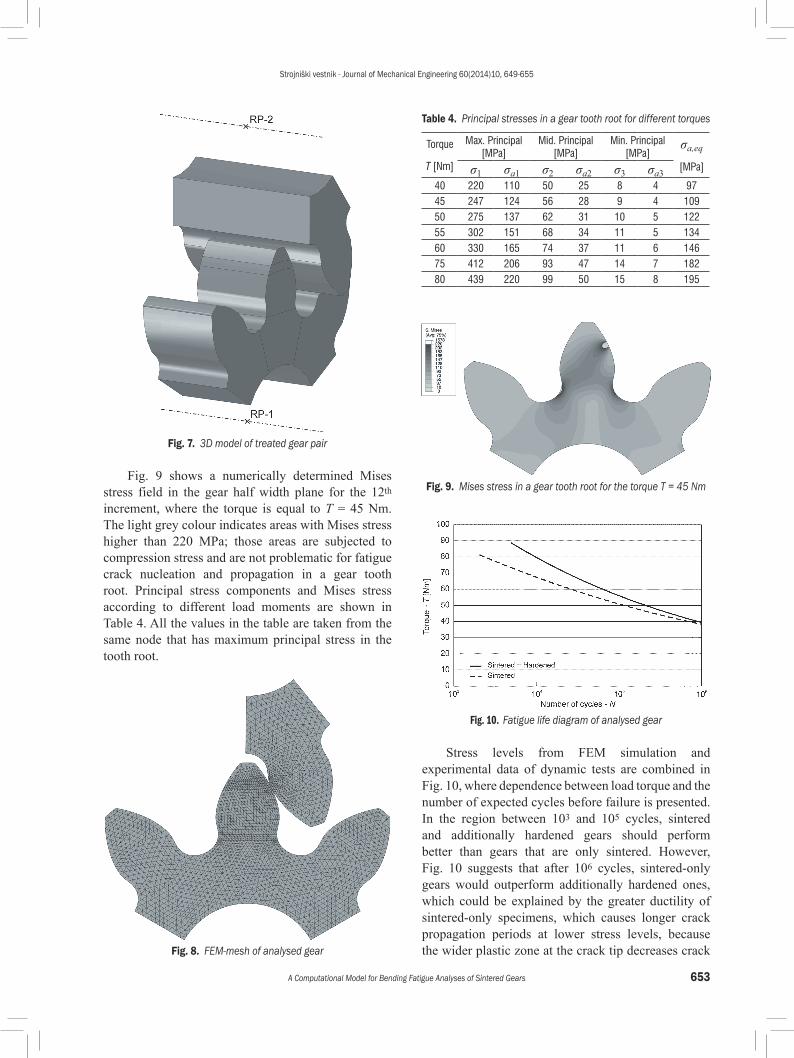
To determine the fatigue life of the treated gear using Eq. (1), the alternating principal stresses σa1, σa2 and σa3 in a gear tooth root should be known. Here, the principal stresses have been determined numerically using FEM-method in the framework of commercial software Abaqus [18]. As seen from Fig. 7, only one third of the discussed gear is modelled (Instance 1) and one tooth of a pairing gear (Instance 2) is added to the assembly in such a way that the contact between the two of them is at the outermost single contact point. The surfaces of shaft holes with a diameter of di = 15 mm and cut result surfaces were coupled to the reference points in such a way that all relative displacements and rotations between them were restricted. All degrees of freedom of both reference points were set to zero at the initial step. In the load step, rotation around the gear axis was applied to a reference point coupled to Instance 1 (RP-1). Because of contact between the teeth, a reaction moment is calculated for the reference point, which is considered to be the torque load to the gear that causes the stress field in the tooth root. This approach was taken because of the significantly greater simulation stability in comparison to the torque boundary condition.
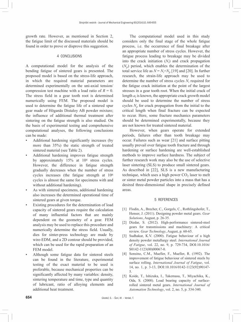
The material of both sections was modelled as linearly elastic with Young’s modulus for hardened sintered steel, which was taken from data obtained by experimental testing of this material discussed in Section 2. Contact between the two sections was modelled as tangentially frictionless and as “hard” contact in the normal direction. The whole assembly was meshed with linear tetrahedral elements of type C3D4H. There were approximately 427,000 elements in Instance 1 and around 64,000 elements in Instance 2 (Fig. 8). Numeric simulation was done in 20 increments. The first increments were used to establish contact between two instances and the rest are used to obtain principal stress components in the tooth root of Instance 1 for different reaction moments. Although stress gradients are covered to consider stress intensity factor dependent on the notch geometry, the material notch sensitivity factor is neglected in this approach.
Strojniški vestnik - Journal of Mechanical Engineering 60(2014)10, 649-655
653A Computational Model for Bending Fatigue Analyses of Sintered Gears
Fig. 7. 3D model of treated gear pair
Fig. 9 shows a numerically determined Mises stress field in the gear half width plane for the 12th increment, where the torque is equal to T = 45 Nm. The light grey colour indicates areas with Mises stress higher than 220 MPa; those areas are subjected to compression stress and are not problematic for fatigue crack nucleation and propagation in a gear tooth root. Principal stress components and Mises stress according to different load moments are shown in Table 4. All the values in the table are taken from the same node that has maximum principal stress in the tooth root.
Fig. 8. FEM-mesh of analysed gear
Table 4. Principal stresses in a gear tooth root for different torques
Torque
T [Nm]
Max. Principal [MPa]
Mid. Principal [MPa]
Min. Principal [MPa]
σa,eq
[MPa]σ1 σa1 σ2 σa2 σ3 σa340 220 110 50 25 8 4 9745 247 124 56 28 9 4 10950 275 137 62 31 10 5 12255 302 151 68 34 11 5 13460 330 165 74 37 11 6 14675 412 206 93 47 14 7 18280 439 220 99 50 15 8 195
Fig. 9. Mises stress in a gear tooth root for the torque T = 45 Nm
Fig. 10. Fatigue life diagram of analysed gear
Stress levels from FEM simulation and experimental data of dynamic tests are combined in Fig. 10, where dependence between load torque and the number of expected cycles before failure is presented. In the region between 103 and 105 cycles, sintered and additionally hardened gears should perform better than gears that are only sintered. However, Fig. 10 suggests that after 106 cycles, sintered-only gears would outperform additionally hardened ones, which could be explained by the greater ductility of sintered-only specimens, which causes longer crack propagation periods at lower stress levels, because the wider plastic zone at the crack tip decreases crack
Strojniški vestnik - Journal of Mechanical Engineering 60(2014)10, 649-655
654 Glodež, S. – Šori, M. – Verlak, T.
growth rate. However, as mentioned in Section 2, the fatigue limit of the discussed materials should be found in order to prove or disprove this suggestion.
4 CONCLUSIONS
A computational model for the analysis of the bending fatigue of sintered gears is presented. The proposed model is based on the stress-life approach, in which the required material parameters are determined experimentally on the uni-axial tension/compression test machine with a load ratio of R = 0. The stress field in a gear tooth root is determined numerically using FEM. The proposed model is used to determine the fatigue life of a sintered spur gear made of Höganäs Distaloy AB powder mixture; the influence of additional thermal treatment after sintering on the fatigue strength is also studied. On the basis of experimental testing and comprehensive computational analyses, the following conclusions can be made:• Additional hardening significantly increases (by
more than 35%) the static strength of treated sintered material (see Table 2).
• Additional hardening improves fatigue strength by approximately 15% at 104 stress cycles. However, the difference in fatigue strength gradually decreases when the number of stress cycles increases (the fatigue strength at 106 cycles is almost the same for specimens with and without additional hardening).
• As with sintered specimens, additional hardening also increases the determined operational time of sintered gears at given torque.
• Existing procedures for the determination of load capacity of sintered gears require the calculation of many influential factors that are mainly dependent on the geometry of a gear. FEM analysis may be used to replace this procedure and numerically determine the stress field. Usually, dies for sinter-press technology are made by wire-EDM, and a 2D contour should be provided, which can be used for the rapid preparation of an FEM model.
• Although some fatigue data for sintered steels can be found in the literature, experimental testing of the exact material to be used is preferable, because mechanical properties can be significantly affected by many variables: density, sintering temperature and time, type and quantity of lubricant, ratio of alloying elements and additional heat treatment.
The computational model used in this study considers only the final stage of the whole fatigue process, i.e. the occurrence of final breakage after an appropriate number of stress cycles. However, the fatigue process leading to breakage may be divided into the crack initiation (Ni) and crack propagation (Np) period, which enables the determination of the total service life as N = Ni+Np [19] and [20]. In further research, the strain-life approach may be used to determine the number of stress cycles Ni required for the fatigue crack initiation at the point of the largest stresses in a gear tooth root. When the initial crack of length ai is known, the appropriate crack growth model should be used to determine the number of stress cycles Np for crack propagation from the initial to the critical length when final fracture can be expected to occur. Here, some fracture mechanics parameters should be determined experimentally, because they are not known for treated sintered material.
However, when gears operate for extended periods, failures other than tooth breakage may occur. Failures such as wear [21] and surface pitting usually prevail over fatigue tooth fracture and through hardening or surface hardening are well-established methods to improve surface hardness. The subject of further research work may also be the use of selective laser sintering (SLS) to produce small sintered gears. As described in [22], SLS is a new manufacturing technique, which uses a high power CO2 laser to melt or sinter metal powder particles into a mass that has a desired three-dimensional shape in precisely defined areas.
5 REFERENCES
[1] Flodin, A., Brecher, C., Gorgels, C., Rothlingshofer, T., Henser, J. (2011). Designing powder metal gears. Gear Solutions, August, p. 26-35.
[2] Dizdar, S. (2012). High-performance sintered-steel gears for transmissions and machinery: A critical review. Gear Technology, August, p. 60-65.
[3] Sudhakar, K.V. (2000). Fatigue behaviour of a high density powder metallurgy steel. International Journal of Fatigue, vol. 22, no. 9, p. 729-734, DOI:10.1016/S0142-1123(00)00067-0.
[4] Sonsino, C.M., Mueller, F., Mueller, R. (1992). The improvement of fatigue behaviour of sintered steels by surface rolling. International Journal of Fatigue, vol. 14, no. 1, p. 3-13, DOI:10.1016/0142-1123(92)90147-5.
[5] Koide, T., Ishizuka, I., Takemasu, T., Miyachika, K., Oda, S. (2008). Load bearing capacity of surface-rolled sintered metal gears. International Journal of Automation Technology, vol. 2, no. 5, p. 334-340.

Strojniški vestnik - Journal of Mechanical Engineering 60(2014)10, 649-655
655A Computational Model for Bending Fatigue Analyses of Sintered Gears
[6] Glodež, S., Flašker, J., Kramberger, J. (2002). A computational model for calculating the bending-load capacity of gears. Strojniški vestnik – Journal of Mechanical Engineering, vol. 48, no. 5, p. 257-266.
[7] Glodež, S., Flašker, J., Pehan, S. (1994). Prediction of service life of spur gears using statistical methods. Strojniški vestnik – Journal of Mechanical Engineering, vol. 40, no. 11-12, p. 393-400.
[8] ISO 6336 (2006). Calculation of Load Capacity of Spur and Helical Gears, International Organization for Standardization, Geneva.
[9] AGMA 930-A05 (2005). Calculated Bending Load Capacity of Powder Metallurgy (P/M). External Spur Gears, Information sheet, 2005.
[10] Stephens, R.I., Fatemi, A., Stephens, R.R., Fuchs, H.O. (2001). Metal Fatigue in Engineering, John Wiley & Sons Inc., New York.
[11] Dowling, N.E. (2007). Mechanical Behaviour of Materials. Pearson Prentice Hall, New York.
[12] Candela, N., Velasco, F., Martinez, M.A., Torralba, J.M. (2005). Influence of microstructure on mechanical properties of molybdenum alloyed P/M steels. Journal of Materials Processing Technology, vol. 168, no. 3, p. 505-510, DOI:10.1016/j.jmatprotec.2004.02.066.
[13] Polasik, S.J., Williams, J.J., Chawla, N. (2002). Fatigue crack initiation and propagation of binder-treated powder metallurgy steels. Metallurgical and Materials Transactions, a-Physical Metallurgy and Materials Science, vol. 33a, p. 73-81, DOI:10.1007/s11661-002-0006-8.
[14] Petrova, A.M., Stepichev, A.V. (1998). Effect of carbon on volume changes during the sintering of an iron-chromiuim material. Powder Metallurgy and Metal Ceramics, vol. 37, no. 5-6, p. 270-273, DOI:10.1007/BF02675860.
[15] Khraisat, W., Nyborg, L. (2004). Effect of carbon and phosphorus addition on sintered density and effect of carbon removal on mechanical properties of high density sintered steel. Materials Science and Technology, vol. 20, no. 6, p. 705-710, DOI:10.1179/026708304225017210.
[16] DIN 30910-4 (2010). Sintered metal materials: Sintered material specifications – Part 4: Materials for structural parts, German standard, Berlin.
[17] Dlapka, M., Danninger, H., Gierl, C., Klammer, E., Weiss, B., Khatibi, G., Betzwar-Kotas, A. (2012). Fatigue behaviour and wear resistance of sinter-hardening steels. International Journal of Powder Metallurgy, vol. 48, no. 5, p. 49-60.
[18] ABAQUS Version 6.12-1 (2012). Dassault Systèmes Simulia Corp., Providence.
[19] Fajdiga, G., Flašker, J., Glodež, S., Ren, Z. (2000). Numerical simulation of the surface fatigue crack growth on gear teeth flanks. Strojniški vestnik – Journal of Mechanical Engineering, vol. 46, no. 6, p. 359-369.
[20] Podrug, S., Glodež, S., Jelaska, D. (2011). Numerical modelling of crack growth in a gear tooth root. Strojniški vestnik – Journal of Mechanical Engineering, vol. 57, no. 7/8, p. 579-586, DOI:10.5545/sv-jme.2009.127.
[21] Miltenović, A., Nikolić, V., Milovančević, M., Banić, M. (2012). Experimental and FEM analysis of sintered steel worm gear wear. Transaction of Famena, vol. 36, no. 4, p. 85-96.
[22] Dobrzanski, L.A., Musztyfaga, M., Drygala, A. (2013). Final manufacturing process of front side metallisation on silicon solar cells using conventional and unconventional techniques. Strojniški vestnik – Journal of Mechanical Engineering, vol. 59, no. 3, p. 175-182, DOI:10.5545/sv-jme.2012.625.