A COMPILATION - NASA · PDF fileThis action produces a signal-level ... Commercially available...
29
NASA SP-5976 (01) (NASA-SP-5976 (01)) MEASUREMENT, TESTING, N75-12343 AND SAFETY TECHNOLOGY: A COMPILATION Technology Utilization (NASA) 28 p HC $1.00 CSCL 14D Unclas G1/38 03701 MEASUREMENT, TESTING, AND SAFETY TECHNOLOGY A COMPILATION A NOI ~ I V, l , c 41FO cz 7 Q0~ U.S.A. 90 z https://ntrs.nasa.gov/search.jsp?R=19750004271 2018-05-02T14:08:45+00:00Z
Transcript of A COMPILATION - NASA · PDF fileThis action produces a signal-level ... Commercially available...

NASA SP-5976 (01)
(NASA-SP-5976 (01)) MEASUREMENT, TESTING, N75-12343AND SAFETY TECHNOLOGY: A COMPILATIONTechnology Utilization (NASA) 28 p HC$1.00 CSCL 14D Unclas
G1/38 03701
MEASUREMENT, TESTING, AND SAFETY TECHNOLOGY
A COMPILATION
A NOI ~ I V, l ,c 41FO
cz 7 Q0~
U.S.A. 90 z
https://ntrs.nasa.gov/search.jsp?R=19750004271 2018-05-02T14:08:45+00:00Z

Foreword
The National Aeronautics and Space Administration has established a TechnologyUtilization Program for the dissemination of information on technological developmentswhich have potential utility outside the aerospace community. By encouraging multipleapplication of the results of its research and development, NASA earns for the public anincreased return on the investment in aerospace research and development programs.
This document is one in a series intended to furnish such technological information.Divided into three sections, this Compilation presents several methods and techniques inthe related areas of measurement, testing, and safety. In Section 1 several measuringtechniques and devices are described. Section 2 presents a number of testing methods anddevices, and Section 3 contains several articles on equipment modifications or proceduresthat may assist in safety and maintenance.
Additional technical information on individual tools and techniques can be re-quested by circling the appropriate number on the Reader Service Card included in thisCompilation.
The latest patent information available at the final preparation of this Compilationis presented on the page following the last article in the text. For those innovations onwhich NASA has decided not to apply for a patent, a Patent Statement is not included.Potential users of items described herein should consult the cognizant organization forupdated patent information at that time.
We appreciate comment by readers and welcome hearing about the relevance andutility of the information in this Compilation.
Jeffrey T. Hamilton, DirectorTechnology Utilization OfficeNational Aeronautics and Space Administration
NOTICE * This document was prepared under the sponsorship of the National Aeronautics and SpaceAdministration. Neither the United States Government nor any person acting on behalf of the UnitedStates Government assumes any liability resulting from the use of the information contained in thisdocument, or warrants that such use will be free from privately owned rights.
For sale by the National Technical Information Service, Springfield, Virginia 22151. $1.00
Contents
Page
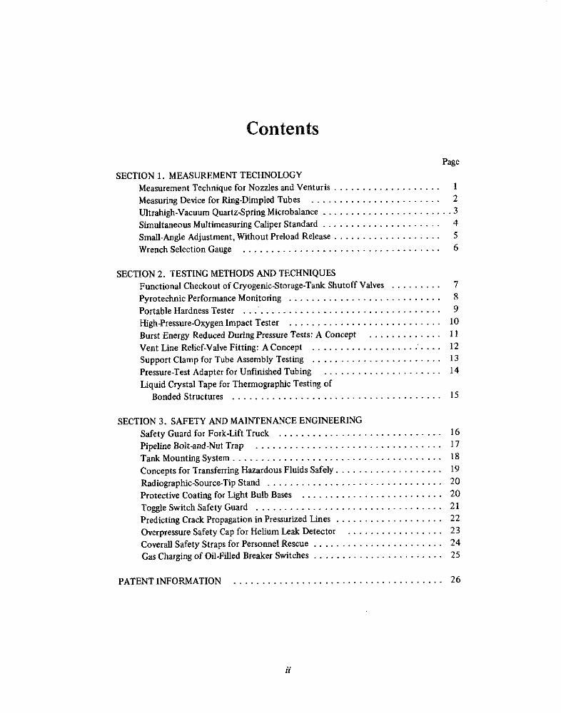
SECTION 1. MEASUREMENT TECHNOLOGYMeasurement Technique for Nozzles and Venturis .................... 1
Measuring Device for Ring-Dimpled Tubes ....................... 2
Ultrahigh-Vacuum Quartz-Spring Microbalance ....................... 3
Simultaneous Multimeasuring Caliper Standard ..................... 4
Small-Angle Adjustment, Without Preload Release ................... 5
Wrench Selection Gauge ..................................... 6
SECTION 2. TESTING METHODS AND TECHNIQUES
Functional Checkout of Cryogenic-Storage-Tank Shutoff Valves ......... 7
Pyrotechnic Performance Monitoring ........................... 8
Portable Hardness Tester ........................................ 9
High-Pressure-Oxygen Impact Tester ........................... 10
Burst Energy Reduced During Pressure Tests: A Concept ............. 11
Vent Line Relief-Valve Fitting: A Concept ................... .... 12
Support Clamp for Tube Assembly Testing ....................... 13
Pressure-Test Adapter for Unfinished Tubing ..................... 14
Liquid Crystal Tape for Thermographic Testing ofBonded Structures ..................................... 15
SECTION 3. SAFETY AND MAINTENANCE ENGINEERING
Safety Guard for Fork-Lift Truck ............................. 16
Pipeline Bolt-and-Nut Trap ................................. 17
Tank Mounting System ...................................... 18
Concepts for Transferring Hazardous Fluids Safely ................... 19
Radiographic-Source-Tip Stand ............................... 20
Protective Coating for Light Bulb Bases ......................... 20
Toggle Switch Safety Guard ................................. 21
Predicting Crack Propagation in Pressurized Lines ................... 22
Overpressure Safety Cap for Helium Leak Detector ................. 23
Coverall Safety Straps for Personnel Rescue ....................... 24
Gas Charging of Oil-Filled Breaker Switches .................. ..... 25
PATENT INFORMATION ............. ....................... 26
ii
Section 1. Measurement Technology
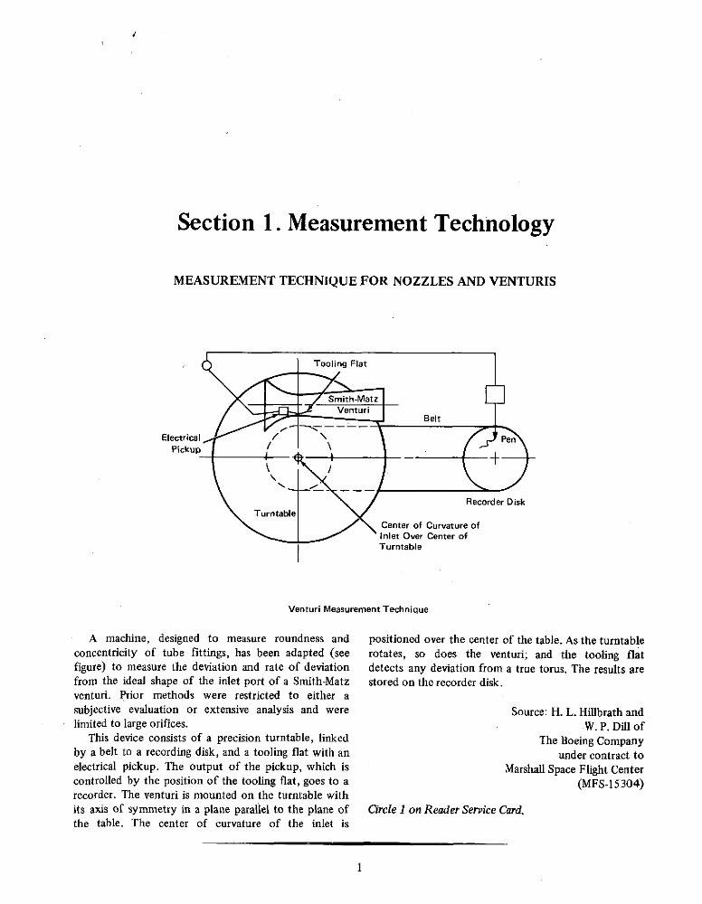
MEASUREMENT TECHNIQUE FOR NOZZLES AND VENTURIS
Tooling Flat
Smith-MatzVenturi
Belt
Electrical / PenPickup
Recorder Disk
TurntableCenter of Curvature of
Inlet Over Center ofTurntable
Venturi Measurement Technique
A machine, designed to measure roundness and positioned over the center of the table. As the turntableconcentricity of tube fittings, has been adapted (see rotates, so does the venturi; and the tooling flatfigure) to measure the deviation and rate of deviation detects any deviation from a true torus. The results arefrom the ideal shape of the inlet port of a Smith-Matz stored on the recorder disk.venturi. Prior methods were restricted to either asubjective evaluation or extensive analysis and were Source: H. L. Hillbrath andlimited to large orifices. W. P. Dill of
This device consists of a precision turntable, linked The Boeing Companyby a belt to a recording disk, and a tooling flat with an under contract toelectrical pickup. The output of the pickup, which is Marshall Space Flight Centercontrolled by the position of the tooling flat, goes to a (MFS-15304)recorder. The venturi is mounted on the turntable withits axis of symmetry in a plane parallel to the plane of Circle 1 on Reader Service Card.the table. The center of curvature of the inlet is
I
2 MEASUREMENT, TESTING, AND SAFETY TECHNOLOGY
MEASURING DEVICE FOR RING-DIMPLED TUBES
Contour Follower
GuidePin Guide
Foot
Frame
View A-A
Linear VariableDifferential Transformer(LVDT)
Compression L ASpring Contour
Follower
Handle Typical Ring-DimpledGuide 1 Tube SectionFoot LVDT Core Frame A
Measuring-Device Assembly and Ring-Dimpled Tube
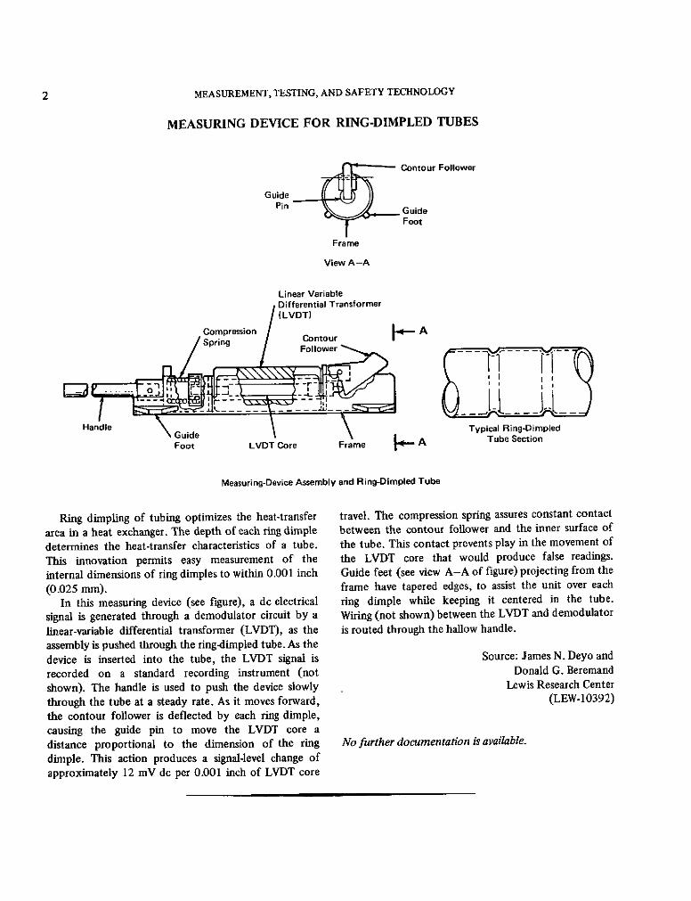
Ring dimpling of tubing optimizes the heat-transfer travel. The compression spring assures constant contact
area in a heat exchanger. The depth of each ring dimple between the contour follower and the inner surface of
determines the heat-transfer characteristics of a tube. the tube. This contact prevents play in the movement of
This innovation permits easy measurement of the the LVDT core that would produce false readings.
internal dimensions of ring dimples to within 0.001 inch Guide feet (see view A-A of figure) projecting from the
(0.025 mm). frame have tapered edges, to assist the unit over each
In this measuring device (see figure), a dc electrical ring dimple while keeping it centered in the tube.
signal is generated through a demodulator circuit by a Wiring (not shown) between the LVDT and demodulator
linear-variable differential transformer (LVDT), as the is routed through the hallow handle.assembly is pushed through the ring-dimpled tube. As thedevice is inserted into the tube, the LVDT signal is Source: James N. Deyo and
recorded on a standard recording instrument (not Donald G. Beremand
shown). The handle is used to push the device slowly Lewis Research Center
through the tube at a steady rate. As it moves forward, (LEW-10392)
the contour follower is deflected by each ring dimple,causing the guide pin to move the LVDT core adistance proportional to the dimension of the ring No further documentation is available.
dimple. This action produces a signal-level change ofapproximately 12 mV de per 0.001 inch of LVDT core
MEASUREMENT TECHNOLOGY 3
ULTRAHIGH-VACUUM QUARTZ-SPRING MICROBALANCE
Viewing Port OuartzSpring WithHook
Primary Vacuum-Ion Pump
MagneticDamper
Watch-Glass Double Cooling Jacket CathetometerBaffle Plate Focused on
- --- - - Reference PointQuartz
Extender Rod Cooling Water Outlet
Heating Jacket With - SampleThermocouples Container
" Cooling Water Inlet
SecondaryVacuum-Ion Pump
Schematic of the Microbalance
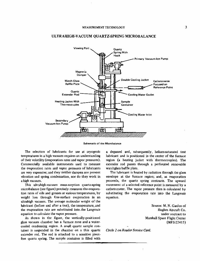
The selection of lubricants for use at cryogenic a degassed and, subsequently, helium-saturated testtemperatures in a high vacuum requires an understanding lubricant and is positioned in the center of the furnaceof their volatility (evaporation rates and vapor pressures). region (a heating jacket with thermocouples). TheCommercially available instruments used to measure extender rod passes through a perforated removablethe evaporation rates and vapor pressures of lubricants watchglass baffle plate.are very expensive; and they neither dampen nor prevent The lubricant is heated by radiation through the glassvibration and spring condensation, nor do they work in envelope at the furnace region; and, as evaporationa high vacuum. proceeds, the quartz spring contracts. The upward
This ultrahigh-vacuum mass-sorption quartz-spring movement of a selected reference point is measured by amicrobalance (see figure) precisely measures the evapora- cathetometer. The vapor pressure then is calculated bytion rates of oils and greases at various temperatures, by substituting the evaporation rate into the Langmuirweight loss through free-surface evaporation in an equation.ultrahigh vacuum. The average molecular weight of thelubricant (before and after a test), the temperature, and Source: M. N. Gardos ofthe evaporation rate are substituted into.the Langmuir Hughes Aircraft Co.equation to calculate the vapor pressure. under contract to
As shown in the figure, the vertically-positioned Marshall Space Flight Centerglass vacuum chamber has a furnace zone and a water- (MFS-22415)cooled condensing region. A small quartz sample con-tainer is suspended in the chamber on a thin quartz Circle 2 on Reader Service Card.extender rod. The rod is attached to a sensitive pivot-free quartz spring. The sample container is filled with

4 MEASUREMENT, TESTING, AND SAFETY TECHNOLOGY
SIMULTANEOUS MULTIMEASURING CALIPER STANDARD
The simultaneous multimeasuring caliper standard(SMMCS) can make simultaneous measurements of anymechanical part, including both internal and externaldimensions. The base of the SMMCS has micrometeradjusting controls on an X-Y positioning platform. Alladjusting and measuring devices are attached to a verticalmetal column mounted on a movable base. The pieceto be measured is placed to the right of the SMMCS, asin Figure . Digital Microadjust
"in 1 Micrometer Tension Lock
MicroadjustTension Spring
MicrometerAnvil
Microadjust Locking ScrewJaw (Rider) (1 of 4)
Traverse and MicroadjustMicroadjust Jaw BaseTraverse Jaw Attachments
(Carrier)
Traverse JawFine Adjust
Figure 2. Simultaneous Multimeasuring CaliperStandard (Back View)
the Z (vertical) plane until its attachment contacts onesurface of the subject piece. The digital micrometer isadjusted to bring the microadjust jaw attachment intocontact with a second surface. Once the desired contactshave been made, they are maintained by the pressure of
Figure 1. Simultaneous Multimeasuring Caliper the microadjust tension spring (see Figure 2). TheStandard (Front View) microadjust tension lock and the locking screws are
then secured, and measurement readings can be taken.In operation, the traverse and microadjust jaws are
separated until their attachments fit the subject piece. Source: Harry W. DaytonEither or both of the jaw attachments can be extended Langley Research Centeror retracted as required, to contact inner and/or outer (LAR-11114)surfaces. The microadjust base is used to move the jawsin the X-Y plane. The traverse jaw (carrier) is moved in No further documentation is available.

MEASUREMENT TECHNOLOGY 5
SMALL-ANGLE ADJUSTMENT, WITHOUT PRELOAD RELEASE
These Two SurfacesMaster Equatorial Eccentric Tangent Arm
Mirror With Respect toMirror Declination Axis
AdjustmentBearing
[EE I Preload ShimDeclination AxisDeclination Bearing
Preload Spacer Eccent, c Oistance0.025 in
Adjustment
Capsule
Surface A Surface B
Polar Axis
Orthogonality Adjustment of Master Equatorial Axes
This technique is used to set shaft angles of an optical The most significant feature of this design is that theinstrument used with a 64m diameter antenna, to orthogonality adjustment can be made without relievingwithin a 0.1 arc second tolerance. It involves (see figure) or changing the preload on the declination-axis maina ball bearing, race-mounted assembly with a center ele- bearings or on any other part of the structure. Whilement slightly offset from concentricity. The outer struc- observing an alignment autocollimator, the set screwsture of the bearing assembly is cylindrical and concentric holding the tangent arm can be turned slightly, thuswith the shaft axis. obtaining an orthogonality accuracy equal to the resolu-
The essential features of the adjustment system are tion of the autocollimator. Considering the accuracy ofshown in the figure. One of the declination-axis angu- the particular autocollimator used for aligning the mas-lar contact ball bearings is mounted within an auxiliary ter equatorial, it is believed that the axis orthogonalitybearing capsule containing a pair of preloaded angu- error does not exceed 0.15 arc seconds.lar contact ball bearings. The bearing capsule is The alignment bearing capsule is fabricated by assem-mounted eccentrically with respect to the bore of the bling the two auxiliary ball bearings between the innerdeclination axis bearing. The position adjustment is exe- and outer rings of the capsule and preloading the bear-cuted by moving the tangent arm attached to the inner- ings to 5000 lb (22.2x10 3 N) by adjusting the preloadmost ring of the auxiliary bearing capsule. The tangent shim thickness until a prescribed drag torque is reached.arm is moved by turning two opposing set screws. The The tangent arm is locked tightly in its neutral positionamount of the auxiliary bearing eccentricity is 0.025 and the open ends of the capsule are temporarily sealed.in. (0.063 cm), and the angular range of the arm is Then the inner and outer cylindrical surfaces of the cap-±10 deg from its neutral position, thus producing a sule assembly are precision-ground to fit the declination±0.0045-in. (0.0114-cm) adjustment range in the direc- bearing and its housing.tion of the x axis. As the two declination-axis bearingsare spaced 26 in. (66 cm) apart, the angular adjustment Source: Houston D. McGinness ofrange is ±34 arc seconds. One turn of the tangent arm Caltech/JPLset screw changes the declination axis angle by 2.10 under contract toarc seconds. Adjustment in the direction is accompanied NASA Pasadena Officeby a displacement in the x direction, but this latter dis- (NPO-10744)placement does not affect the orthoganality of theaxes. Circle 3 on Reader Service Card.

6 MEASUREMENT, TESTING, AND SAFETY TECHNOLOGY
WRENCH SELECTION GAUGE
Wrench Gauge U. S. - Metric A pocket-sized wrench gauge (see figure) enables theuser to determine the bolt-head or nut size in either
Inch MM Inch U.S. or metric units. Thirty-two sizes are provided
1.0 between 3/16 in. (4.76 mm) and 1.0 in. (25.4 mm).25 -3/16 This eliminates the prior practice of trial and error, or
31/32- 5 the selection of the "nearest fit" of several wrenches7/32 when the proper wrench is actually available. Correct
24 6 size is determined on the wrench gauge by direct15/16- 23 7 1/4 readout, a time saving that increases production. This29/32 22 is particularly helpful, in view of the current transistion
7/8- from the U.S. to the metric scale.27/32- 21 9 1132
13/16-
25/32 20 10 3/8 Source: J. H. Kimzey3/4 1913/32 Johnson Space Center
18 (MSC-12590)23/32 -7/16
121711/16 15/3217 13 No further documentation is available.21/32- 1/2
5/8 - 17/32
19/32-15 9/16
9/16
- - ' I

7
Section 2. Testing Methods and Techniques
FUNCTIONAL CHECKOUT OF CRYOGENIC-STORAGE-TANKSHUTOFF VALVES
Liquid LevelIndicator
Pressure TransferRegulator V 2 :; Irl - System
P1HY P2
GN2 or He Supply
To Facility Drain o
SManual Valve
[ Pneumatically Operated Valve (Remote)
OPressure Gauge
Cryogenic Valve Functional Checkout System
Cryogenic (very low temperature) fluids require is opened until pressure P2 equals pressure P 1. Valve V1sophisticated transfer systems. These include pneumat- can then be functionally checked without cryogenicically operated valves that must be functionally checked fluid flow.at regular intervals. In the past, liquid flow through asystem, caused "fluid hammer," a damaging phenome- Source: Bruno Drescher ofnon, and a loss of liquid. The Boeing Company
A new system design (see figure) permits a functional under contract totest of the pneumatically operated valves, from fully Kennedy Space Centerclosed to fully open, without involving the stored (KSC-10155)cryogenic fluid. Pressure at valve V1 is equalized bygaseous nitrogen (GN 2 ). With valve V4 closed, valve V2 Circle 4 on Reader Service Card.

8 MEASUREMENT, TESTING, AND SAFETY TECHNOLOGY
PYROTECHNIC PERFORMANCE MONITORING
A study has been made to provide users of pyro- A second velocity measurement is obtained bytechnic systems with performance comparisons among impacting the piston against an energy sensor containingsquibs, initiators, and gas-generating cartridges. Parame- an aluminum honeycomb of known uniform crush
ters studied included: ignition characteristics, combustion strength.. The crush strength displacement, multiplied bydynamics, and delivery mechanisms. the known crush strength, provides an energy measure-
A dynamic test device (Figure 1) provides informa- ment in inch-pounds.
tion on mechanical energy delivered and combustion
Cylinder 1-PoundCylinder Housing Piston
PressureTransducer - 0.250 in. FoilFaceSwitches Clamp
Piston Needle (5)
Front View
Energy1/4 in. Switch Sensor
BlocksInitiator (5)Port
Initiator PressurePort Transducer
Po't
SealingRing
Figure 1. Cross Section of Dynamic Test Device 16 in.
dynamics in an actual (gas-generating device) application. LeadA velocity-monitoring fixture (Figure 2) is used in Screwconjunction with the dynamic test device of Figure 1to measure the force acting on a one-pound piston. Figure 2. Velocity-Monitoring Fixture for Dynamic Test Device
The internal volume of the dynamic test device ispressurized by firing the gas-generating device, causingthe piston to accelerate through a one-inch stroke.Velocity of the piston is measured by recording thetime intervals between contacting of the five electrically- Source: Laurence J. Bement
charged foil switches by the electrically grounded needle Langley Research Center
mounted on the forward end of the piston. The (LAR-10800)functional characteristics of ignition and pressure arealso recorded on a high-response magnetic-tape recorder. Circle 5 on Reader Service Card.

TESTING METHODS AND TECHNIQUES 9
PORTABLE HARDNESS TESTER
Super-Hard Ball Release
Figure 1. Portable Hardness Tester Showing SpringLoaded Indentor Ball at Tip
Micrometer Scale Eyepiece
Figure 2. Optical Micrometer Used to MeasureIndentor Ball Impression at 100 X.
It is well known in the field of steel metallurgy that a 0.037 in. (0.76 to 0.94 mm) in diameter. An optical
relationship exists between ultimate strength and hard- micrometer (Figure 2) with a magnification power of
ness. This relationship has been investigated for electro- 100 is then used to determine the precise diameter of
formed nickel, in order to evaluate the mechanical the impression on the surface. The diameter of the
properties at various positions in the electroform. impression is compared to a conversion chart (prepared
A portable hardness tester (Figure 1) was developed from standard-hardness test blocks), and both the yieldto determine the strength properties of irregularly and ultimate strengths of the component area under
shaped components of electroformed nickel (EFNi). test are determined.
Portable Brinell testers leave unacceptable large surfaceimpressions, and other portable testers are not useful Source: E. F. Green of
with irregular shapes. Rockwell International Corp.
The portable tester is hand held at right angles to the under contract to
surface of the test item. When a trip release is operated, Marshall Space Flight Center
a calibrated spring drives a 1/16-in. (1.59-mm) super- (MFS-19167)
hard metal ball into the surface of the test specimen,leaving a circular impression approximately 0.030 to Circle 6 on Reader Service Card.

10 MEASUREMENT, TESTING, AND SAFETY TECHNOLOGY
HIGH-PRESSURE-OXYGEN IMPACT TESTER
Impact testers have been used to test the combustioncharacteristics of materials in a pure oxygen atmosphere.However, prior testers were limited to oxygen pressures
<2>up to 10.4x10 6 N/m 2 (1500 psi), and data were neededat much higher pressures.
Electromagnet Pointer This impact tester (see figure) operates over aElectromagnet pressure range from 10.4x10 4 N/m 2 (15 psi) to 6.9x10 7
N/m2 (10,000 psig) and over a temperature range fromClamp the boiling point of liquid oxygen [90 K (-2970 F)] to
394 K (2500 F). Energy up to 137 J (100 ft-lb) is
supplied when a falling weight impacts the end of aMagnetic PlatePlummet Assembly striker shaft, with its tip in pressure-balanced suspen-
sion immediately above an enclosed sample. The testsample, an 17.5-mm (11/16-in.) disk, is held in a cup
Guide Bar (3) within an impact cell, which provides transducer-controlled heating and cooling plus a small area for the
pressurized oxygen. The pressure-balanced striker shaftis suspended, in contact with but not resting on thesample, by GN 2 acting on a midmounted diaphragm
Timer Pickup that contacts the shaft guide passage.Instrumentation readout of cell temperature and
pressure is provided by a four-channel dual-beam oscillo-Base Plate Plunger (Striker Pin) scope, with sweep times from seconds to microseconds.
and Guide An external-velocity gate trigger records instantaneous-
event (moment-of-impact) data, falling-weight velocity,high-frequency pressure response, and impact-load cellresponse. This analog output is recorded on film fromthe oscilloscope display.
Concrete Base Source: G. A. Hood and F. A. Raniere ofCup Assembly Rockwell International Corp.
under contract toMarshall Space Flight Center
High-Pressure-Oxygen Impact Tester (MFS-19162)
Circle 7 on Reader Service Card.
TESTING METHODS AND TECHNIQUES 11
BURST ENERGY REDUCED DURING PRESSURE TESTS: A CONCEPT
Figure 1.Liquid-Filled FlexibleBellows Line
Figure 2.Plastic, Glass, or MetallicShaped Objects
Figure 3.Plastic or MetallicFlexible Bundle, Similarto Fiberoptics
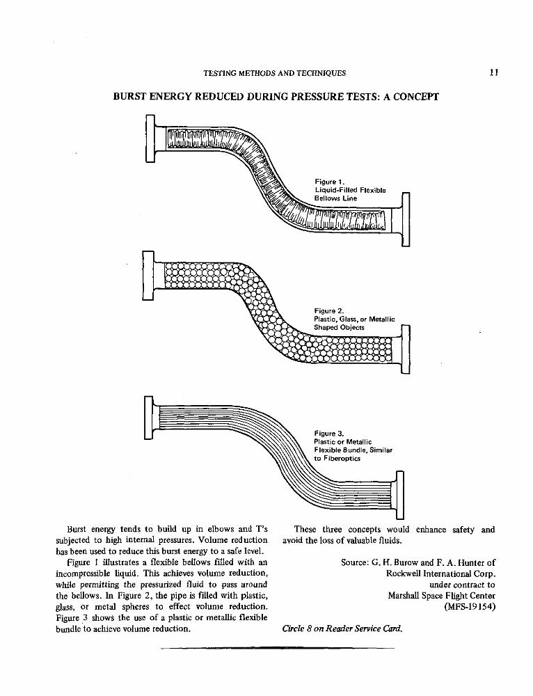
Burst energy tends to build up in elbows and T's These three concepts would enhance safety andsubjected to high internal pressures. Volume reduction avoid the loss of valuable fluids.has been used to reduce this burst energy to a safe level.
Figure 1 illustrates a flexible bellows filled with an Source: G. H. Burow and F. A. Hunter ofincompressible liquid. This achieves volume reduction, Rockwell International Corp.while permitting the pressurized fluid to pass around under contract tothe bellows. In Figure 2, the pipe is filled with plastic, Marshall Space Flight Centerglass, or metal spheres to effect volume reduction. (MFS-19154)Figure .3 shows the use of a plastic or metallic flexiblebundle to achieve volume reduction. Circle 8 on Reader Service Card.

12 MEASUREMENT, TESTING, AND SAFETY TECHNOLOGY
VENT LINE RELIEF-VALVE FITTING: A CONCEPT
V1 Common Vent Line
Vent From for Several Relief ValvesRelief Valve
To Be Tested
V2
Quick Disconnect to LeakFlow Instrumentation
Figure 1. Presently Used Leak Test Connections.(Typical for Each of Several Relief Valves)
Connector to Leak-Leak Flow InstrumentationTest
Fitting
Test Probe
Coupling Nut
Figure 2. Proposed Leak Test Fitting and Probe
Relief valves connected to a common vent line were testing, the seal cap is replaced with a test probe aspreviously leak tested by the setup illustrated in Figure 1. shown in Figure 2. This probe penetrates the Tee andIn normal operation, valve V1 is open and valve V2 is isolates the common vent line from the relief valve,closed, connecting the relief valve to the common vent directing any leakage to the leak-flow instrumentation.line. Leaks were detected by closing valve V1 andopening valve V2 , connecting the relief valve through Source: W. E. Wiley ofthe quick disconnect to instrumentation for measuring Rockwell International Corp.leak flows. under contract to
This innovation is a novel Tee-connector (Figure 2) Johnson Space Centerwhich replaces the series of valves in Figure 1. The (MSC-17783)connector is sealed with a cap (not shown) which isheld in place by a coupling nut. For relief-valve leak No further documentation is available.

TESTING METHODS AND TECHNIQUES 13
SUPPORT CLAMP FOR TUBE ASSEMBLY TESTING
ClampingWashers
Center-Drilled
Hex Nut Bolt
Figure 1. Clamp Assembly
Center-DrilledBolt
Tubing Hex Nut
Figure 2. Clamp in Place on Tubing
A simple tube-support clamp is useful for making This clamp could be useful in passing tubing throughtemporary runs of fluid lines during a system mockup sheet-metal members in automobile body assemblies.and test. The clamp consists of a center-drilled bolt,two clamping washers, and a hex nut. The bolt is Source: R. A. Bender ofdrilled out to contain the OD. of the tubing; the Rockwell International Corp.clamping washers are placed over the bolt threads, and under contract tothe hex nut is run up on the bolt but is not tightened. Johnson Space CenterThis assembly (see Figure 1) is then slid over the (MSC-17603)tubing (see Figure 2) and is forced into an open-endslotted support bracket. The hex nut is then turned to No further documentation is available.force the clamping washers against the opposite facesof the support bracket.

14 MEASUREMENT, TESTING, AND SAFETY TECHNOLOGY
PRESSURE-TEST ADAPTER FOR UNFINISHED TUBING
Seal Compressor Gland
Standard TubeFitting
1/4-InchTube
Pressure-Test Adapter
In high-pressure tubing systems, brazed joints are the barrel, which constricts the grip around the un-better than fittings. For system checkout, however, the finished tubing. When submerged in water and filledtube ends are flared and temporary fittings are used. with 6.9x10 7 N/m 2 (10,000 psi) of helium, flowing atAfter testing, the flares are removed and the joints are 103 cm 3 /s (STP) (61 in.3 /s), the joints do not leak.brazed. This method is time consuming and expensive.
This quick-use device (see figure) adapts to bare un- Source: G. R. Taylor offinished tubing for checkout at very high pressures McDonnell Douglas Corp.[up to 12.4x10 7 N/m 2 (18,000 psi)]. under contract to
The figure shows a compression fitting of a split-grip Marshall Space Flight Centerand compression gland that grips a standard unfinished (MFS-21439)(not flared) tube and mates it with a standard tubefitting. Tightening the gland compresses the Teflon sealagainst the seal compressor, driving the split grip against Circle 9 on Reader Service Card.

TESTING METHODS AND TECHNIQUES 15
LIQUID-CRYSTAL TAPE FOR THERMOGRAPHIC TESTINGOF BONDED STRUCTURES
Tape containing liquid crystals in a protective matrix, and a stopwatch was started. At suitable times, photo-backed and supported by black plastic film, has been graphs were taken as the face of each panel heated upused successfully in thermographic testing of bonded through the color-transition range of the liquid crystalstructures. The composition of the liquid crystal is tape. The irradiation time for each photograph wasvaried to provide ranges of sensitivities of thermographic recorded. After one face of a panel was photographed,response. The black film improves color display by it was allowed to return to room temperature; and thereflected light. procedure was repeated for its reverse side. The test
In this test procedure, selected bonded panels, results compared favorably with those reported previ-fabricated with specific built-in defects, were treated ously, for the same test panels coated directly bywith liquid crystal tape on both sides, were heated to sprayed-on liquid crystals.various temperatures, and then were photographed. Eachpanel was photographed with a copying camera with its Source: M. L. Tanzer ofaxis perpendicular to the panel. The panels were Hoffman-La Roche, Inc.irradiated by four quartz-iodide lamps. The lamps were under contract toin reflector mounts and were rated at 650 watts each, Marshall Space Flight Centerwith a color temperature of 3200 K. (MFS-22441)
When the camera was focused and the aperture andexposure controls were set, the lamps were turned on, Circle 10 on Reader Service Card.
16
Section 3. Safety and Maintenance Engineering
SAFETY GUARD FOR FORK-LIFT TRUCK
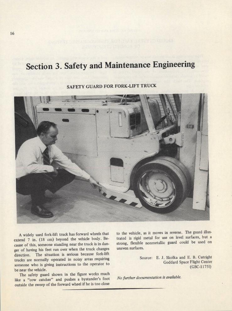
A widely used fork-lift truck has forward wheels that to the vehicle, as it moves in reverse. The guard illus-
extend 7 in. (18 cm) beyond the vehicle body. Be- trated is rigid metal for use on level surfaces, but a
cause of this, someone standing near the truck is in dan- strong, flexible nonmetallic guard could be used on
ger of having his feet run over when the truck changes uneven surfaces.
direction. The situation is serious because fork-lift
trucks are normally operated in noisy areas requiring Source: E. J. Skolka and E. B. Cutright
someone who is giving instructions to the operator to Goddard Space Flight Center
be near the vehicle. (GSC-11751)
The safety guard shown in the figure works much
like a "cow catcher" and pushes a bystander's foot No further documentation is available.
outside the sweep of the forward wheel if he is too close

SAFETY AND MAINTENANCE ENGINEERING 17
PIPELINE BOLT-AND-NUT TRAP
SupportingRibs
Ring
Pipeline Bolt-and-Nut Trap
This pipeline trap is designed to operate under All of the above-listed design-criteria objectives havepressures to 12.4x10 6 N/m2 (1800 psi) and at fluid been accomplished in this novel pipeline bolt-and-nutvelocities to 45 m/s (150 ft/s). trip (see figure) consisting of concentric rings, welded to
The trap basically consists of concentric rings, welded supporting ribs, which in turn are welded to a supportto supporting ribs, which in turn are welded to a support ring that is recessed into a special pipe flange. Slots inring that is recessed into a special pipe flange. the concentric rings are used to offset the loss in flow
Commercially available strainers for pipelines are not area resulting from the thickness of the rings and thesuitable for service where bodies 5/16 in. (7.9 mm) and supporting ribs.larger are to be restrained at high pressures and velocities. This device may be of interest to industries utilizingUnder these conditions, such metal bodies smash through high-speed fluid transportation, for preventing damageany conventional-type strainer. Limitations imposed by stray solid objects.upon the design of a suitable trap include the following:(1) The pipe size may not be enlarged, in order that the Source: Leo Berner oftrap may readily be removed to restore an unencumbered Aerojet-General Corp.straight pipe run; (2) Flow restrictions causing an under contract toincrease of fluid velocities have to be held to an absolute Lewis Research Centerminimum; and (3) Length of the trap has to be as short (LEW-90558)as feasible to fit the limited available space in thecompact pipeline. No further documentation is available.
18 MEASUREMENT, TESTING, AND SAFETY TECHNOLOGY
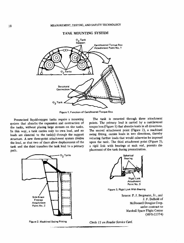
TANK MOUNTING SYSTEM
02 TankSupport
Attachment Point No. 1
02 TanksT e
Connection n f
02 Tank
Figure 1. Function of Cantilevered Torque Box
Pressurized liquid-oxygen tanks require a mounting The tank is mounted through three attachment
system that absorbs the expansion and contraction of points. The primary load is carried by a cantilevered
the tanks, without placing large stresses on the tanks. torque box (Figure 1) that absorbs loads in all directions.
In this way, a tank carries only its own load, and no The second attachment point (Figure 2), a machined
loads are directed to the tank(s) through the support swing fitting, carries loads in two directions, thereby
structure. A new three-point attachment system divides reducing further loads that would otherwise be imposed
the load, so that two of them allow displacement of the upon the tank. The third attachment point (Figure 3),
tank and the third transfers the tank load to a primary a rigid link with bearings at each end, permits dis-
path. placement of the tank during pressurization.
02 'Tanks SphericalBearing
Rigid LinkAttachmentPoint No. 3
Figure 3. Rigid Link With Bearing
Side-Brace LSource: P. J. Bergmann, Jr., and
Fittings J. F. DeBold ofAttachment McDonnell Douglas Corp.Point No. 2 under contract to
Marshall Space Flight Center(MFS-22374)
Figure 2. Machined Swing Fitting Circle 11 on Reader Service Card.
SAFETY AND MAINTENANCE ENGINEERING 19
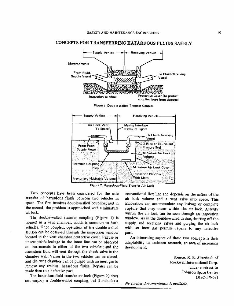
CONCEPTS FOR TRANSFERRING HAZARDOUS FLUIDS SAFELY
- Supply Vehicle Receiving Vehicle
(Environment)
From Fluid- To Fluid-ReceivingSupply Vessel Vessel
Inspection Window Protective Cover (to protectcoupling hose from damage)
Figure 1. Double-Walled Transfer Couples
Supply Vehicle Receiving Vehicle
Air Lock Vent Mating InterfaceTo Space (Pressure Tight)
To Fluid-Receiving_ _ Vessel
-FroRing or EquivalentFrm sluid ,Pressure Seal
Supply V e s s e l
Miniature Air LockVolume
Installed CouplingHose Miniature Air Lock Cover
Inspection WindowPressurized Habitable Volume With Light
Figure 2. Hazardous-Fluid Transfer Air Lock
Two concepts have been considered for the safe conventional flex line and depends on the action of thetransfer of hazardous fluids between two vehicles in air lock volume and a vent valve into space. Thisspace. The first involves double-walled coupling; and in innovation can accommodate any leakage or completethe second, the problem is approached with a miniature rupture that may occur within the air lock. Activityair lock. within the air lock can be seen through an inspection
The double-walled transfer coupling (Figure 1) is window. As in the double-walled device, shutting off thehoused in a vent chamber, which is common to both supply and receiving valves and purging the air lockvehicles. Once coupled, operation of the double-walled with an inert gas permits repairs to any defectivesection can be observed through the inspection window part.located in the vent chamber protective cover. Failure or An interesting aspect of these two concepts is theirunacceptable leakage in the inner line can be observed adaptability to undersea research, an area of increasingon instruments in either of the two vehicles; and the development.hazardous fluid will vent through the check valve in thechamber wall. Valves in the two vehicles can be closed, Source: R. E. Altenbach ofand the vent chamber can be purged with an inert gas to Rockwell International Corp.remove any residual hazardous fluids. Repairs can be under contract tomade then to a defective part. Johnson Space Center
The hazardous-fluid transfer air lock (Figure 2) does (MSC-17968)not employ a double-walled coupling, but it includes a
No further documentation is available.

20 MEASUREMENT, TESTING, AND SAFETY TECHNOLOGY
RADIOGRAPHIC-SOURCE-TIP STAND
SourTe- Radiographic inspection is used to detect flaws in
Holder metal pipes, tubes, elbows, and similar parts. Under
typical field conditions, it may be difficult to positionthe radiation source in correct relationship to the subjectand film. Floor stands in general use are heavy, bulky,and frequently require two men to adapt them for best
results.A radiographic-source-tip stand (see figure) can be
Support Rod used by one man. It is simple and lightweight. The
angle base of the holder is taped to the pipe near the areato be inspected. The source-tip holder is positioned by
Wingbolt I loosening the wingbolt and sliding the support rod up or
down in the guide tubing with proper rotation. The
wingbolt is tightened when the correct position is
reached.
Guide Tubing ISource: Ralph E. Peterson of
Sunder contract to
Angle Kennedy Space CenterBase (KSC-10549)
No further documentation is available.
Pipe
Radiographic-Source-Tip Stand
PROTECTIVE COATING FOR LIGHT BULB BASES
The vitreous insulator bases of single- and double- Source: L. D. Menges of
contact light bulbs are brittle and easily cracked or McDonnell Douglas Corp.
chipped during shipment and installation. This is a under contract to
serious problem in a zero-gravity environment where Marshall Space Flight Center
free particles cannot be tolerated. (MFS-22421)
A protective coating of an epoxy sealant has beenused to protect vitreous insulation from cracking and Circle 12 on Reader Service Card.
chipping. This technique should be useful in otherapplications where insulator damage must be avoided.

SAFETY AND MAINTENANCE ENGINEERING 21
TOGGLE SWITCH SAFETY GUARD
Pin 1
LockLever
Pin 2
/ Guard Cover
Down
To Open
Position 1
Lock Lever
L Guard Cover
SReady to Open
Down andOpen
Position 2
Toggle Switch Safety Guard
This safety guard may be used with critical switches, switch is just as accessible, but the operator is put onto prevent them from being operated by mistake. In notice that it is a critical switch.position 1 in the illustration (toggle on or off), the locklever engages pin 1, and the guard cover cannot be Source: P. J. Rossimoved on its pivot at pin 2. Moving the lock lever to Rockwell International Corp.position 2 releases the guard cover, allowing it to be under contract toraised on its pivot (at pin 2) to uncover the toggle. Johnson Space Center
Compared to key-operated guards, this guard provides (MSC-15638)the extra safety of one additional operation. The toggle
No further documentation is available.

22 MEASUREMENT, TESTING, AND SAFETY TECHNOLOGY
PREDICTING CRACK PROPAGATION IN PRESSURIZED LINES
AttachmentClis Crack to be
Monitored
DisplacementGauge
Crack Propagation Test Setup
Surface-crack propagation in pressurized lines can strip-chart recorder which receives signals from the
now be predicted more accurately than by previous displacement gauge. This technique could be used to
methods. Test samples of a 6.0-m (20-ft) length of continuously monitor large storage vessels, so that repairs
Inconel 718 pipe 7.6 cm (3 in.) in diameter, welded to to propagating cracks could be optimally scheduled.
stainless-steel 321 flanges, have been monitored for
weld-crack propagation under simulated operational Source: R. E. Brady of
conditions of pressure and temperature. Rockwell International Corp.
Dye penetrant is used initially to locate a surface under contract to
crack. A displacement gauge (see figure) is then placed Marshall Space Flight Center
over the crack and held in place by clips that are spot (MFS-24053)
welded to the pipe surface on either side of the crack.
The line is pressurized, in a test setup, to its normal Circle 13 on Reader Service Card.
operating pressure; and crack behavior is recorded on a

SAFETY AND MAINTENANCE ENGINEERING 23
OVERPRESSURE SAFETY CAP FOR HELIUM LEAK DETECTOR
Lightweight Cap forPressure Release
Sleeve Safety
SafetyCable
BodyCutaway View
Overpressure Safety Cap
Mass-spectrometer helium leak-test units have a large respectively; and is held in place by two restrictingalternate inlet used with special large-chamber tests, in sleeves. When overpressure forces the lightweight capaddition to the smaller line, connections used for most from the inlet body, the safety cable restricts captests. Rupture of a defective burst disk in the smaller movement to the length of the cable between theline can apply as much pressure as 2.07x10 6 N/m2 restricting sleeves.(300 psi) to the system, and may often project theheavy alternate-inlet closure cap into the test area at Source: K. R. Hubbs ofhigh velocity. Rockwell International Corp.
An overpressure safety cap can be used in place of the under contract toprevious cap to avoid the danger of personal injury and Johnson Space Centerequipment damage. The lightweight cap (see figure) is (MSC-17172)conventionally fastened to the inlet body. A safety cableis fitted in slots around the cap and the inlet body, No further documentation is available.

24 MEASUREMENT, TESTING, AND SAFETY TECHNOLOGY
COVERALL SAFETY STRAPS FOR PERSONNEL RESCUE
ShoulderPickupStraps S
51.0 cm (20 in)
BackWebbing
Reinforcement 22.9 cm (9 in)
Double Hem
Suit
HipStrap
Nylon WebbingReinforcement On-Side
SeamBack Front
Dot SnapFasteners
Coverall Safety Straps
Nylon safety straps sewed to workers' coveralls (see With this safety strap arrangement, a subject wearing
illustration) aid rescuers in removing disabled wearers difficult-to-handle coveralls can be grabbed with confi-
from dangerous environments. The tape used for these dence from any angle of approach. He can be moved
straps is 2.54 cm (1 in.) wide, type 2 MIL-T-5038 nylon, readily to a more favorable treatment position in case of
The straps are so placed that, regardless of the position serious injury. Two to six people can use the straps to
of the wearer, the rescuer can always use one or more share the load in a manner that avoids the aggravation
to effect rapid movement of the subject. of severe injuries such as fractures, hematomae, or
Shoulder pickup straps are sewed around and under internal damage.the arms, giving good support of the subject's body in
an upright carry. The back webbing reinforcement joins Source: Henry M. Waddell, Jr., of
the shoulder straps, and together they mechanically Rockwell International Corp.
force the shoulders and front of the garment to share under contract to
the load in a facedown horizontal carry. Tapes 22.9 cm Kennedy Space Center
(9 in.) long are attached to each side of the garment on (KSC-10815)
each of the vertical side seams, about 51.0 cm (20 in.)down from the tapes of the shoulders. These support Circle 14 on Reader Service Card.
the hips in a horizontal carry as the subject rests oneither side.

SAFETY AND MAINTENANCE ENGINEERING 25
GAS CHARGING OF OIL-FILLED BREAKER SWITCHES
CompoundPressure-Vacuum
Gauge
Oil Level Gauge
Schraeder Valve
Viewing Window
Operating Handle
Gas-Charging Arrangement for Oil-Filled Breaker Switches
Dry nitrogen gas has been used to maintain pressure (see figure). The method permits the use of a portableon oil-filled breaker switches. Pressure above the oil is gas bottle and hoses to pressurize, purge, and re-required to ensure complete immersion of the switches, pressurize the breaker-switch tank.to prevent arcing during operation. Periodically, theswitches are cleaned and purged with nitrogen, refilled Source: F. M. Hoog ofwith fresh oil, and repressurized with nitrogen. This is Trans World Airlinesdone by installing a permanent hose-and-valve arrange- under contract toment in the pressurized tank gaugeline. Kennedy Space Center
This method uses a Schraeder valve,which is generally (KSC-09981)used to inflate automobile tires, in the tank gaugeline
No further documentation is available.

26
Patent Information
The following innovations, described in this Compilation, have been patented or
are being considered for patent action as indicated below:
Simultaneous Multimeasuring Caliper Standard (Page 4) LAR-11114
Inquiries concerning rights for the commercial use of this invention should be
addressed to:Patent Counsel
Langley Research CenterCode 456Hampton, Virginia 23665
Pyrotechnic Performance Monitoring (Page 8) LAR-10800
This invention has been patented by NASA (U.S. Patent No. 3,670,559). Inquiries
concerning nonexclusive or exclusive license for its commercial development should be
addressed to:Patent CounselLangley Research Center
Code 456Hampton, Virginia 23665
High-Pressure-Oxygen Impact Tester (Page 10) MFS-19162
Inquiries concerning rights for the commercial use of this invention should be
addressed to:Patent CounselMarshall Space Flight Center
Code CC01Marshall Space Flight Center, Alabama 35812