A Comparison ofthe Fit of Spark-Eroded Titanium Copings and Cast
8
A Comparison ofthe Fit of Spark-Eroded Titanium Copings and Cast Gold Alloy Copings /an R. Harris, BDS, MSc, FDSRCS Registrar ludith L Wickens, BDS, MSc, FDSRCS Consultant Department of Conservative Dentistry Eastman Dental Hospital London, England The fit of spark-eroded titanium and cast gold alloy copings was compared by assessment of retrieved cement film analogues. This technique was chosen for its simplicity, nondestructive nature, and for the information it provided on overall fit. The present study showed that the overall fit of titanium copings wa5 comparable to that of gold copings. In marginal areas, the space between die and coping was found to be larger for spark-eroded than cast copings, Int I Prosthodont 1994:7:348-355. T he accuracy of fit of a crown or fixed partial denture retainer is considered important, and poorly fitting restorations may render the tooth more susceptible to microleakage, caries, and pul- pitis,'- Laboratory and clinical studies have been devised to assess the overall or marginal fit of restorations,'"" Such techniques may be broadly divided into direct and indirect methods (Fig 1 ], Although lost-wax casting of gold is an ancient art" with widespread use and almost universal acceptance, it is not without limitations.'- The process comprises a sequence of laboratory stages, each of which may introduce a new source of error and all of which may be cumulative. Whilst many of these problems can be avoided, they are suf- ficiently frequent to be both time-consuming and costly. The fact that these errors may occur cumu- latively may make an individual casting anything from slightly less than perfect to clinically un- acceptable, A number of different approaches have been tried to overcome some of the lost-wax casting lim- itations,"" The Procera system (Nobelpharma AB, Gothenburg, Sweden) combines copy-milling with spark erosion (or electrical discharge machining) to produce titanium copings,'^"'" These copings are designed to be veneered with a low-fusing porce- lain to form metal ceramic crowns. Reprint requests: Dr ludith L. Wickerts, Department of Con- servative Dentistry, Eastman Dentai Hospital, London WCIX 8LD, England. This process is fundamentally different from a lost-wax casting technique. It might therefore be expected that differences would exist between the internal surfaces of cast copings and those of spark-eroded copings made for the same tooth preparation. The purpose of this study was to compare the fit of spark-eroded titanium copings with that of cast gold alloy copings made for the same tooth preparations. Materials and Methods A modification of a metbod first described by McLean and von Fraunhofer In 1971" was used to evaluate the overall fit of a restoration. This tech- nique should not be used to provide information on the size of the external marginal gap, as other techniques provide more accurate information on this measurement (Fig 1 ]. Die and Coping Preparation A mandibular first molar ¡vorine tooth (Columbia Dentoform, New York, NY] was prepared as a master die (Fig 2) using a tungsten carbide tapered fissure bur in a handpiece mounted in a paral- lelometer. The preparation incorporated the fol- lowing features; 1, A total convergence angle of 10 degrees 2. A buccal chamfer finish line, 1.5 mm deep I o( Proslhodomics 348 í7. Number 4, 1994
Transcript of A Comparison ofthe Fit of Spark-Eroded Titanium Copings and Cast
A Comparison ofthe Fitof Spark-Eroded Titanium
Copings and Cast GoldAlloy Copings
/an R. Harris, BDS, MSc, FDSRCSRegistrar
ludith L Wickens, BDS, MSc, FDSRCSConsultant
Department of Conservative DentistryEastman Dental HospitalLondon, England
The fit of spark-eroded titanium and cast gold alloy copings was comparedby assessment of retrieved cement film analogues. This technique waschosen for its simplicity, nondestructive nature, and for the information itprovided on overall fit. The present study showed that the overall fit oftitanium copings wa5 comparable to that of gold copings. In marginal areas,the space between die and coping was found to be larger for spark-erodedthan cast copings, Int I Prosthodont 1994:7:348-355.
T he accuracy of fit of a crown or fixed partialdenture retainer is considered important, and
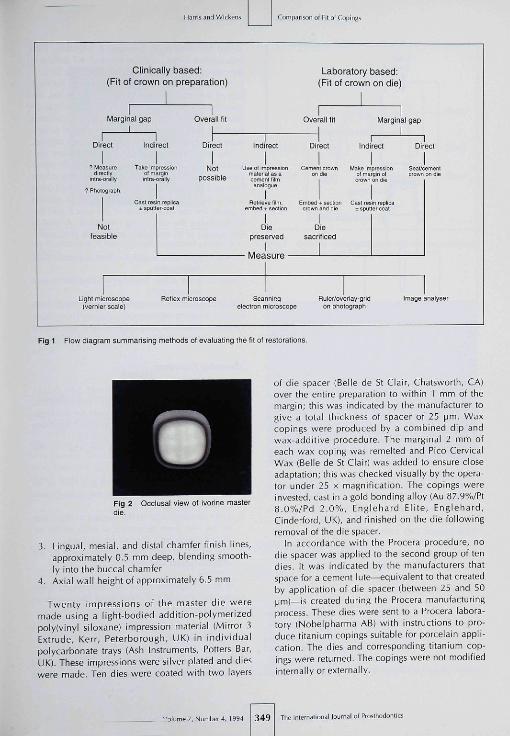
poorly fitting restorations may render the toothmore susceptible to microleakage, caries, and pul-pitis,'- Laboratory and clinical studies have beendevised to assess the overall or marginal fit ofrestorations,'"" Such techniques may be broadlydivided into direct and indirect methods (Fig 1 ],
Although lost-wax casting of gold is an ancientart" with widespread use and almost universalacceptance, it is not without limitations.'- Theprocess comprises a sequence of laboratory stages,each of which may introduce a new source of errorand all of which may be cumulative. Whilst manyof these problems can be avoided, they are suf-ficiently frequent to be both time-consuming andcostly. The fact that these errors may occur cumu-latively may make an individual casting anythingfrom slightly less than perfect to clinically un-acceptable,
A number of different approaches have beentried to overcome some of the lost-wax casting lim-itations,"" The Procera system (Nobelpharma AB,Gothenburg, Sweden) combines copy-milling withspark erosion (or electrical discharge machining) toproduce titanium copings,'^"'" These copings aredesigned to be veneered with a low-fusing porce-lain to form metal ceramic crowns.
Reprint requests: Dr ludith L. Wickerts, Department of Con-servative Dentistry, Eastman Dentai Hospital, London WCIX8LD, England.
This process is fundamentally different from alost-wax casting technique. It might therefore beexpected that differences would exist between theinternal surfaces of cast copings and those ofspark-eroded copings made for the same toothpreparation.
The purpose of this study was to compare thefit of spark-eroded titanium copings with that ofcast gold alloy copings made for the same toothpreparations.
Materials and Methods
A modification of a metbod first described byMcLean and von Fraunhofer In 1971" was used toevaluate the overall fit of a restoration. This tech-nique should not be used to provide informationon the size of the external marginal gap, as othertechniques provide more accurate information onthis measurement (Fig 1 ].
Die and Coping Preparation
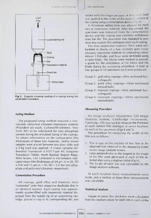
A mandibular first molar ¡vorine tooth (ColumbiaDentoform, New York, NY] was prepared as amaster die (Fig 2) using a tungsten carbide taperedfissure bur in a handpiece mounted in a paral-lelometer. The preparation incorporated the fol-lowing features;
1, A total convergence angle of 10 degrees2. A buccal chamfer finish line, 1.5 mm deep
I o( Proslhodomics 348 í7. Number 4, 1994
Clinically based:(Fit of crown on preparation)
ison oí Fil oí Copings
Laboratory based:(Fit of crown on die)
tviarginal gap Overall titI
Overall tit Marginal gap
Direct Indirect Direct Indirect Direct Indirect
? Measure Take impiession fsjot Use ol impression CemBnr crown Make impression Seat̂ cemenfinr'̂ orally inlríSy possible 'oermrll̂ trf """'^ ofmarg.nol orovmonOie
Notfeasible
Die Diepreserved sacriticed
I IMeasure '
Light rnicroscope(vernier scale)
Relleï microscope Scann i rgelectron microscope
Rjier/overlay-griflon phologrâpil
image analyser
Fig 1 Flow diagram summarising methods ot evaluating the tit ot restorations.
Occlusal view ot ivonne master
3. Lingual, mesial, and distal chamfer finish lines,approximately 0,5 mm deep, blending smooth-ly into the buccal chamfer
4, Axial wall height of approximately 6.5 mm
Twenty impressions of the master die weremade using a light-bodied addition-polymerizedpoly(vinyl siloxane) impression material (Mirror 3Extrude, Kerr, Peterborough, UK) in individualpolycarbonate trays (Ash Instruments, Potters Bar,UK), These impressions were silver plated and dieswere made. Ten dies were coated with two layers
of die spacer (Belle de St Clair, Chatsworth, CA)over the entire preparation to within 1 mm of themargin; this was indicated by the manufacturer togive a total thickness of spacer of 25 |jm. Waxcopings were produced by a combined dip andwax-additive procedure. The marginal 2 mm ofeach wax coping was remelted and Pico CervicalWax (Belle de St Clair) was added to ensure closeadaptation; this was checked visually by the opera-tor under 25 x magnification. The copings wereinvested, cast in a gold bonding alloy (Au 87,9%/Pt8,0%/Pd 2.n%, Englehard Elite, Englehard,Cinderford, UK), and finished on the die followingremoval of the die spacer.
In accordance with the Procera procedure, nodie spacer was applied to the second group of tendies. It was indicated by the manufacturers thatspace for a cement lute—equivalent to that createdby application of die spacer (between 25 and 50|jni)—is created during the Procera manufacturingprocess. These dies were sent to a Procera labora-tory (Nobelpharma AB) with instructions to pro-duce titanium copings suitable for porcelain appli-cation. The dies and corresponding titanium cop-ings were returned. The copings were not modifiedinternally or externally.
••)lume7,Nuniber4,1994 349 The Internaiional lojmai of Proílliodontics
Comparison of F¡f oí Copings
5kg
-Load-bearing rod
Siud
Coping
DieImpression material
-Do we i pin
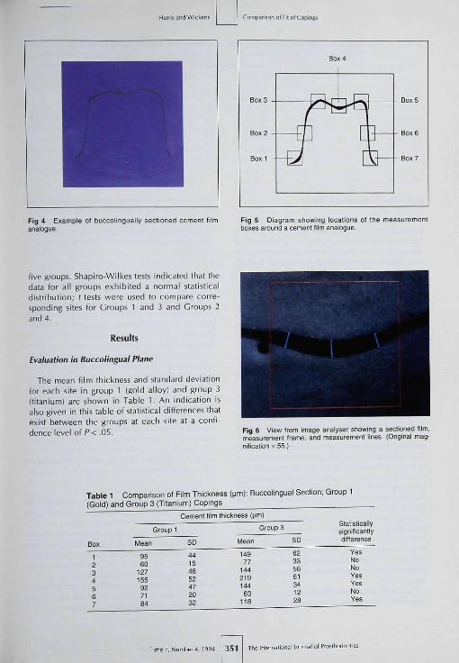
Fig 3 Diagram showing loading of a coping during ttiecementation procedure.
seated with firm finger pressure. A 5-kg '.."ic loadwas applied to the centre of the occlusal •surface ofthe coping using a cementation device iFig 3).
A 10-minute setting time was allowed for eachmix of impression tnaterial. After this period, thespecimen was removed from the cementationdevice and the coping was carefully withdrawnfrom the die. The procedure was repeated to pro-duce two cement film analogues from each coping.
The thin impression material films were em-bedded in blocks of a low-viscosity poly (vinylsiloxane] impression material of contrasting colour(Mirror 3 Extrude), and these were sectioned usinga razor blade. The blocks were marked to providea guide for the orientation of the block and theblade during the sectioning procedure. A total offour groups of 10 specimens each were produced;
Group 1 : gold alloy copings^ilms sectioned buc-colingually
Group 2: gold alloy copings—films sectionedmesiodistally
Group 3: titanium copings—films sectioned buc-colingually
Group 4: t i tanium copings—films sectionedmesiodistally
Luting Medium
The proposed luting method required a low-viscosity poly(vinyl siloxane) impression material(President )et wash, Coltene/Whaledent, NewYork, NY) to be substituted for zinc phosphatecement during the simulated luting of the copings.To obtain information on the comparative filmthicknesses of these two materials, freshly mixedsamples were placed between two glass slabs anda 5-kg load was applied. A linear variable dif-ferentia! transducer (LVDT-Type AC SangamoTransducer 76666, North Barsted, Bognor Regis,West Sussex, UK) calibrated in micrometers indi-cated mean film thicknesses of 24 pm (n - 20, SD= 0.8) and 13 [jm(n = 20, SD - 2.1) for zinc phos-phate and poly(vinyl siloxane), respectively.
Cementation Procedure
All copings, gold alloy and t i tanium, were"cemented" onto their respective duplicate dies Inan identical manner. Each coping was approxi-mately quarter-filled with impression material dis-pensed from the nozzle tip of an automixing car-tridge, placed on top of its corresponding die, and
Measuring Procedure
An image analyser {Quantimet 520 ImageAnalysis System, Cambridge Instruments,Cambridge, UK) was used to measure the thicknessof each cement film analogue at seven locationson each of the specimens (Figs 4 and 5).
The procedure for measuring the width of thefilm was as follows:
1. The image of the section of the f i lm to beobserved was centered in the measuring frameon the image analyser screen.
2. Lines perpendicular to the tangent to the imageof the film were generated at each of the se-lected sites using a digitiser tablet (Fig 6).
3. The length of each line was calculated by theimage analyser software.
At each location three measurements weremade, and a median of these three measurementswas calculated.
Statistical Analysis
Values of mean film thickness were calculatedfrom the median values for each site in each of the
a I of Pro5thoiionlic5 350 Voiume 7, Number 4, ! 994
Harri; and Wie kens Comparison ol Fit of CopinR
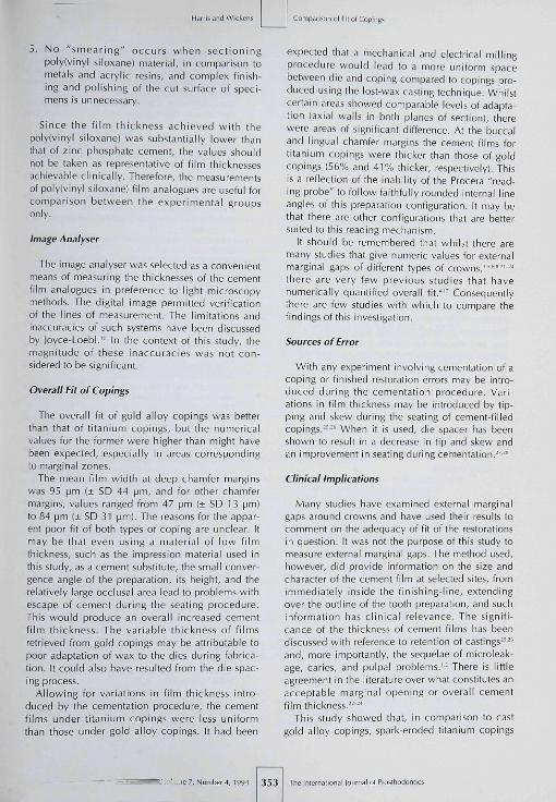
Fig 4 Example ot buccolingually sectioned cement filmanalogue.
Fig 5 Diagram showing locations of ttie measyrementboxes around a cement tilm analogue.
five groups. Shapiro-Wilkes tests indicated that thedata for all groups exhibited a normal statisticaldistribution; f tests were used to compare corre-sponding sites for Groups 1 and 3 and Croups 2and 4.
Results
Evaluation in Buccolmgual Plane
The mean film thickness and standard deviationfor each site in group 1 (gold alloy) and group 3(titanium) are shown in Table 1. An indication isalso given in this table of statistical differences thatexist between the groups at each site at a confi-dence level of P< .05. Fig 6 View trom image analyser showing a sectioned film,
measurement trame, and measurement lines. (Original mag-nification X 55.)
Table 1 Comparison of Film Thickness (pm): Buccolingual Section; Group 1(Gold) and Group 3 (Titanium) Copings
Cement film thickness (|jm)
Box
1234567
Group 1
Mean
9560
127155927184
SD
44154852472032
Group 3
Mean
14977
14421914463
118
SD
62335661341228
Statisticallysignificantlydifference
YesNoNoYesYesNoYes
•7, Number 4, 1594 351 The International lournal of Prostliodontii

iioiiüt fil of Coping;
Table 2 Comparisoti of Film Thickness (fjtn): Mesiodistal Section; Group 2 (Gold)and Group 4 (Titanium) Copings
Box1234567
Group 2
Mean
73449B
133110
5747
Cement film thickness (pm¡
SD
26106071742413
Group 4
Mean
13256
1321831608494
SD
37175560273822
Statisticailysignificantlydifférencie
YesNoNoNoNoNoYes
Evaluation in Mesiodistal Plane
The mean film fhickne.« and standard deviationfor each site in group 2 (^old alloy] and group 4(tifanium) are shown in Table 2. An indication isalso given in this table of statistical differences fhatexist befween fhe groups af each sife at a confi-dence level of P< .05.
Discussion
This sfudy used a rtiaster die rafher than fhe pre-pared tooth. It would have been possible to use thesame method in vivo to retrieve such films fromunder any indirect restoration prior fo luting. Thetechnique is versatile and has broad application.
The Procera technique is based on a copy-milling procedure, both to shape the externalsurface of the fifanium coping and to mill the elec-trodes that will form its internal surface. The accu-racy with which the ball-end probe can trace thesurface detail of a die will govern the accuracy offit of the finished coping. Such constraints dictatethat preparations for Procera crowns should haverounded internal line angies and smooth surfaces.The technique cannot accommodate preparationswith sharp shoulders, steep bevels, or undercuts;fhese factors may limil the clinical situations inwhich the technique can be used. The preparationfor the master die was designed taking such con-straints into consideration.
Whilst not necessarily representative of clinicaldies, the design ofthe master die used in this studyincorporated features from several types of toothpreparation with the intention of assessing theextent of the capabilities of the Procera process. Itwas also suitable as a die from which to make lost-wax castings.
Die spacer was applied to the silver-plated dieson which cast copings were made. This allowed
space for cement between the crown and die, aid-ing seating of the restoration during cementation.The dies for which titanium copings were fo bemade received no die spacer, since space forcement is created during the Procera manufactur-ing process.
Cementation and Sectioning Techniques
McLean and von Fraunhofer" originally de-scribed tbe use of a polyether impression materialllmpregum, ESPE, Seefeld, Germany) as a cementfilm analogue. They used an cpimine resin material{Scutan, ESPE) to embed their retrieved films,claiming that the two materials combined chemi-cally and that the width of the rubber film wasclearly distinguishable, it is questionable whetherchemical combination of the two maferials is desir-able, as bitjrring of the interfacial zone can makethe measuring procedure less accurate. The rigidset of fhe embedding resin necessitated the use ofsawing, grinding, and polishing procedures in thepreparation of specimens.
In the present investigation low-viscositypolyivinyl siioxane) maferials were selected for thefollowing reasons:
1. They were readily available.2. When appropriate colours were selected, the
embedded film was clearly visible and easilymeasured using the image analyser.
3. The two materials chosen adhered to oneanother but did not react chemically; conse-quently no blurring of the interfacial zoneoccurred and a clear line of demarcation wasvisible facilitating measurement.
4. Poly(vinyl siioxane] materials are accuratedimensionally stable, and exhibit low perma-nent deformations,'=--"
The International Iclirnal of Proilhodunrii 352 Volume 7, Number 4, 1994
Härri5 .md Wicken^ Comfi.iiison ot Rt ol Copirgs
5, No "smearing" occurs when sectioningpolylvinyl siloxane) material, in comparison tometals and acrylic resins, and complex finish-ing and polishing of the cut surface of speci-mens is unnecessary.
Since the f i lm thickness achieved with thepoly(vinyl siloxane) was substantially lower thanthat of zinc phosphate cement, the values shouldnot be taken as representative of film thicknessesachievable clinically. Therefore, the measurementsof polyivinyl siloxane) film analogues are useful forcomparison between the experimental groupsonly.
¡mage Analyser
The image analyser was selected as a convenientmeans of measuring the thicknesses of the cementfilm analogues in preference to light microscopymethods. The digital image permitted verificationof the lines of measurement. The limitations andinaccuracies of such systems have been discussedby Joyce-Loebl,'" In the context of this study, themagnitude of these inaccuracies was nol con-sidered to be significant.
Overall Fit of Copings
The overall fit of gold alloy copings was betterthan that of titanium copings, but the numericalvalues for the former were higher than might havebeen expected, especially in areas correspondingto marginal zones.
The mean film width at deep chamfer marginswas 95 [jm (± SD 44 [jm, and for other chamfermargins, values ranged from 47 [jm (± SD 13 pm)to 84 [im 1± SD 31 [im). The reasons for the appar-ent poor fit of both types of coping are unclear. Itmay be that even using a material of low filmthickness, such as the impression material used inthis study, as a cement substitute, the small conver-gence angle of Ihe preparation, its height, and therelatively large occlusal area lead to problems withescape of cement during the seating procedure.This would produce an overall increased cementfilm thickness. The variable ihickness of filmsretrieved from gold copings may be attributable topoor adaptation of wax to the dies during fabrica-tion. It could also have resulted from the die spac-ing process.
Allowing for variations in film thickness intro-duced by the cementation procedure, the cementfilms under titanium copings were less uniformthan those under gold alloy copings. It had been
expected lhat a mechanical and electrical millingprocedure would lead lo a more uniform spacebetween die and coping compared to copings pro-duced using the lost-wax casting technique. Whilstcertain areas showed comparable levels of adapta-tion (axial walls in both planes of section), tberewere areas of significant difference. At the buccaland lingual chamfer margins the cement films fortitanium copings were thicker Ihan those of goldcopings (56% and 41% thicker, respectively]. Thisis a reflection of the inability of Ihe Procera "read-ing probe" to follow faithfully rounded internal lineangles of Ihis preparation configuration. It may bethat there are other configurations that are bettersuited to this reading mechanism.
It should be remembered that whilst there aremany studies that give numeric values for externalmarginal gaps of different types of crowns,"""-' '•'there are very few previous studies that havenumerically quantified overall fit,"" Consequentlythere are few studies with which to compare thefindings of this investigation.
Sources of Error
With any experiment involving cementation of acoping or finished restoration errors may be intro-duced during the cementation procedure. Vari-ations in film thickness may be introduced by tip-ping and skew during the seating of cement-filledcopings,-'-' When it is used, die spacer has beenshown to result in a decrease in tip and skew andan improvement in seating during cementation,-'"
Clinical Implications
Many studies have examined external marginalgaps around crowns and have used their results tocomment on ihe adequacy of fit of the restorationsin question. It was not the purpose of this study tomeasure external marginal gaps. The method used,however, did provide information on the size andcharacter of the cement film at selected sites, fromimmediately inside the finishing-line, extendingover the outline of the tooth preparation, and suchinformation has clinical relevance. The signifi-cance of the thickness of cement films has beendiscussed with reference to retention of castings""and, more importantly, the sequelae of microleak-age, caries, and pulpal problems,'- There is littleagreement in the literature over what constitutes anacceptable marginal opening or overall cementfilm thickness,-- -'
This study showed that, in comparison to castgold alloy copings, spark-eroded titanium copings
• 7. Numtier 4, 1994 353 The Inlernalionai iournai o( Pcoslllodoiili<

of Fit of Copingi
have larger spaces between die and coping in mar-ginal areas. In addition to the clinical implications,this feature may result in technical difficultieswhen "cutting back" titanium copings for the pro-duction of all-porcelain labial margins. Large gapsbetween die and coping in this region will makefabrication of the porcelain margin difficult. Theresulting metal ceramic crown may have inade-quately supported porcelain in the marginal areaand may be susceptible to fracture of the ceramicmaterial in this region.-''"
It has been shown that, even on a die of a prepa-ration designed to be ideally suited to the Proceramanufacturing process. Procera copings do not fitas accurately as gold alloy copings in the marginalarea.
Conclusions
A modified McLean and von Fraunhofer tech-nique provided information on the character of acement film analogue of poly(vinyl siloxane)Impression material retrieved from between a cop-ing and the die for which it was constructed.Within the limitations of the study design, the fol-lowing conclusions may be made:
1, The cement films retrieved from spark-erodedand gold copings were not of a uniform thick-ness.
2, The mean film thickness in all marginal regionsof spark-eroded titanium copings was greaterthan the corresponding regions of cast goldalloy copings.
Acknowledgments
The authors wish to acknowledge the assistance ofNobelpharma AB, Gothenburg, (provision of titanium copingsand loan of gold bonding alloy), and Mrs Pauline Barher (adviceon image analysis techniques).
References
1, Schwartz NL, Whitsett LD, Berry TC, Stewart JL, Un-serviceable crowns and fixed partial dentures: lite spansand causes for loss of serviceability. JADA 1970;81 :1395-1401,
2, Walton JN, Gardiner FM, Agar ¡R. A survey of crown andfixed partial denture failures: length of service and rea-sons for replacemeni, I Proslhet Dent t986i56:41 6-420,
3, Shiíiingburg HT, Hobo S, Fisher DW, Preparation designand margin distortion in porcelam-fused-to-metal restora-tions. I Prosthet Dent 1973:29:276-284.
4, Zena RB, Khan Z, Von Fraurihofei |A. Shoulder prepara-tions for collarless metal-ceramic crowns: Hand planingas opposed to rotary instrumentation. | Prosthet Dent1989:62(31:273-277,
5, Sorensen JA, A standardized method for delcimination otrown margin fidelity, i Prosthet Dent i'-jyü;íj4:18-24,
6, Cooney |P, Richter WA, MacEntee Ml. Evaluation oceramic margins for metal-ceramic restorations, I ProstheDent1985;54:1-5,
7, Sato T, Wohiwend A, Scharer P. Marginal fit in a "shrink,free" ceramic crown system. Int | Periodont Rest Den1986:3:9-21,
8, Chan C, tHaraszlhy G, Geis-Cerstorfer |, Weher HHuettemann H, Scanning electron microscopic studies oithe marginal fit of three esthetic crowns. Quintessence Inil989:20:t89-193.
9, Davis DR, Comparison of fit of two types of all-ceramiccrown. I Prosthet Dent 1988:59:12-16.
10. loyce-Loebl R, Image Analysis: Principles and Practice, eo1. Gteat Britain: Joyce-Loebl, ¡985:65-82,
11. Hunt LB, The long hisioiy of lost wax casting. GoldBulletin 1980:13:63-79,
12. Craig RG, Restorative Dental Materials, ed 8, St LouisMosby, 1969:457-479,
1Î, Rekow D. Computer-aided design and manufacturing irdentistry: A review of the state of the art. J Proslhet Denl1987:58:512-516,
14. Duret F, Preston JD. CAD/CAM imaging in dentistry.Current Opinion Denl 1991:1:150-154,
15. Andersson M, A unique method for fabrication of a crownrestoration using titanium, Tandlakarlidningen 1987;79:640-642.
16. Andersson M, Bergman B, Bessirg C, Ericsson C, LundquisiP, Nilson H, Clinical results with titanium crowns fabri-cated with machine duplication and spark erosion. ActaOdontol Scand 1989:47:279-286,
17 McLean JW, Von Fraunhofer |A, The estimation of cementfilm thickness by an in vivo technique, Br Dent I 1971,I j 1 :107-n i ,
18. Craig RG, Restorative Dental Materials, ed 8, St LouisMosby, 1969:293-346,
19. Craig RC. Review of dentai impression materials. InNIDR, International State-of-the-Art Conference on Re-siorative Dental Materials, Bethesda: 1986:20-26,
20. Craig RG, Properties of 12 addition silicones comparedwith other rubber impression materials. Philip's ] ResIZahnmed 1986:3:244,
21. Abbate M, Tjan AFHL, Fos WM. Comparison of the mar-ginal tit of various ceramic crown systems, | Prosthet Denl1989;61:527-531,
22. Christensen G|, Marginal fit of gold inlay castings, ,Prosthet Denl 1966:16:297-305,
23. Gardner FM, Margins of complete crowns—A literaturereview. | Prosthet Dent I982;48:396-400,
24. Hunter A|, Hunter AR. Cingival margins for crowns: ̂review and discussion. Part II: Discrepancies and configu.rations. | Prosthet Dent 1990,64:636-642.
25 lorgensen KD, Factors affecting the film thickness of zintphosphate cements. Acta Odontol Scand 1960:18:479-^90.
26, Jorgensen KD, Esbensen AL, The relationship between filrrIhickness of zinc phosphate cement and the retention oveneer crowns. Acta Odontol Scand !968;26:169-175,
27, Eames WB, O'Neil S|, Monteiro J, Milier C, Roan |DCohen KS. Techniques to improve the sealing ot castingsJADA 1978,96:432,
28, Fusayama T, Ide K, Hosada H, Relief of resistance ocemeni of full cast crowns. I Prosthet Dent 1964:14:95,
29, Preslon |D, Rational approach to tooth preparation foiceramo-metal restorations. Dent Clin North Am 197721:683-698.
The Intemalional lournal of Prosrhodontii 354 Volume 7, Nurrber 4, 1994
Comparison oí Fil ol Copings
30. Hobo S, Shiilingburg HT. Porcelain fused to mêlai: Toothpreparalion and coping design, i Proslhel Dent 1973;30:28-35.
31. Stein RS, Kuwala M. A dentist and a dentai technologistanalyse current cerarno-metal procedures. Deni ClinNorlh Am 1977;2t:729-749.
32. Kuwata M. Color Atlas of Ceramo-Melal Technology, volI. Tokyo: Ishiyaku EuroAmerica 1 9B6:236-250.
33. Naylor WP. inlroduclion to Melal Ceramic Technology.Chiciigo: Quintessence 1992:64.
Lileralure Abstracts
Fluoride Uptake in Human Dentine From Glass-lonomer Cement In Vivo
Fluoride (F) release from glass-ionomer restorative materials is considered impon:ant in reducing the incidenteand severity of secondary caries. Past investigation into F release from F-containing restorative rnaleiials hascentered around in vitro studies or sampling of deciduous teeth, typically using an electron microprabe ana-lyzer with relatively low limits of resolution. The present study sampled permanent third molar leeth to investi-gate the F profile and F uptake in dentine directiy below glass-ionomer restorations in vivo, using the chemicalquantitative analysis. Nine volunteers (25 years of age), who were scheduled for extraction of maxillary thirdmolars, were used. Two cylindrical cavities were prepared on each occlusal surface, 2.5 mm in depth and 1.5mm in diameter One cavity was restored with an F..releasing glass ionomer material, and the other wasrestored with zinc phosphate cement as a control. Three months post restoration, the experimental teeth wereextracted, histologicaily sectioned, and prepared for abrasive microsampling and chemical analysis. Resultsdemonstrated F concentrations to be highest Immediately beneath the glass-ioncmer restored cavit}', decreas-ing gradually toward the pulpal surface, rising again before reaching the pulpal surface. The average penetra-tion of F from the giass-ionomer material was about three fifths into the dentine interior, with maximum F con-centrations reach approximateiy 1.0 mm from the dentinoenamel junction. The authors concluded that thereis marked uptake of F hy the dentine underlying glass-ionomer restore cavities as demonstrated in permanentteeth in vivo.
Mukai M. lkedaM,¥anagiharaT. et al.Ari:fisOfaffiio/t993;îa:1093-1098. References: 19. Reprints: M. Mukai, Departmeniof Operative Denliitry, School of DenHstiy. Aichi-Gakuin University, 2-11 Suemori-dori, Chikusa-ku, Nagoya 464, Japan.—David R. Cafífia, DMD, The University oí Texas Health Science Center stSsn Amonio, San Antonio, TetSí.
A New Concept in Maxillary Implant Surgery: The Osteotome Technique
In the less than ideal circumstances typically found in the posterior maxillae, where bone quality and quantityare poor, bony corte* is thin oi absent, and sinus location limits ideal impiant positioning, conventionalimplant site preparation may prove detrimental. This article describes the osteotome technique that usessequentially sized cross-sectionally round osteotome for implant site osteotomy. Convention site preparationinto type IV bone using a graded series of drills is often associated with (1) loss or reduction of tactile sensitivi-ty (2) reduced visibility because of contra-angle interference and water-spray irrigation; 131 removal of valuableb¿ne in the drilling process; and (4) generation of potentially damaging heat. In contrast, osteotomy beginningwith a narrow-tipped osteotomes and progressing to on that approximates the cross-sect ion a i dimension of theimpiant may forego many of the previously mentioned shortcomings. As opposed to the drilling, the osleotonietechnique ¡1) maintains existing bone by pushing bone aside upon osteotome insertion with minimal physicaland thermal trauma, rather than limiting bone from the osteotomy site; (2) compacts bone lateral to theosteotomy site resullinc in a denser bone/implant interface; (31 improves bony contour by widening the ridgeas osteotomes of increasing diameter are inserted; (4) elevates the sinus floor as osseous material is pushed infront of the advancing osteotome; and (5) improves visibility and access with precise control and ahgnmerntcapability The author reports dramatic success with 143 consecul.vely placed press-fit implants in type IVhone, owing much of this success to the reported improvements in implant site preparation with theosteotome technique.
Summers RB Ccnipendiam t994;15152-I62 References: 17. Reprints: RobertB Summers DMtJ, 2 E Montgomery,̂ ve™a,« 0 4 Airdrome E y i v a n i a 14oOZ.-Dav:d R. Cagoa. DMD, The Vnivers.ty of Texas Heaith Saer^ce Cenier a; San Ar,ton,o,5sn Antonio, Texas
7, Number 4, 1994 355 The Inlernationaf lournal of Praslhodontii