A comparison of three-dimensional stress distribution and ...
9
RESEARCH Open Access A comparison of three-dimensional stress distribution and displacement of naso- maxillary complex on application of forces using quad-helix and nickel titanium palatal expander 2 (NPE2): a FEM study Avinash Kumar * , Hajra Ghafoor and Arifa Khanam Abstract Background: Our objectives are to analyse and to compare the stress distribution and displacement of the craniofacial structures, following the application of forces from quad-helix and Nickel Titanium Palatal Expander-2 (NPE2) using finite element analysis. Methods: Three-dimensional finite element models of young dried human skull, quad-helix appliance and NPE2 were constructed, and the initial activation of the expanders was stimulated to carry out the analysis and to evaluate the Von Misses stresses and displacement. Results: Both the models demonstrated the highest stresses at the mid-palatal suture, with maximum posterior dislocation. The second highest stress was recorded at the fronto-zygomatic suture. The pattern of stress distribution was almost similar in both the groups, but NPE2 revealed lower magnitude stresses than quad-helix. The only exception being quad-helix model showed high stress levels around pterygo-maxillary suture whereas minimal stress around pterygo-maxillary suture was noticed after NPE2 activation. The cusp of the erupting canine and the erupting mesiobuccal cusp of the second molar showed outward, backward and downward displacement signifying increase in their eruption pattern following maxillary expansion. Conclusions: Maxillary expansion using quad-helix and NPE2 can be used in posterior crossbite correction in cases where maximum skeletal changes are desirable at a younger age; it is furthermore effective in treating young patients with impacted or displaced teeth. Quad-helix and NPE2 produced acceptable forces for orthopaedic treatment even after being orthodontic appliances; their clinical application should be correctly planned as the effects of these appliances are largely age dependent. Background Maxillary expansion treatments have been used for more than a century to correct maxillary transverse deficiency. The earliest common cited report was that of E.C. An- gell published in Dental cosmos in 1860; however, the work was discredited at that time but the technique was generally accepted [1]. Slow maxillary expansion produces more physiologic response at the mid-palatal suture area. It produces less tissue resistance, since it delivers constant physiologic force in the suture and allows better bone formation, both these factors help to minimize the post expansion relapse [2]. Quad-helix has been evolved from the W arch of coffin by the incorporation of helical loops, two anteriorly and two posteriorly, which increased the flexibility and range of action of the appliance [3]. Arndt [4] introduced nickel titanium palatal expanders in the year 1993. Corbett [5] introduced Nickel Titanium Palatal Expander-2 (NPE2) in 1997. It generates optimal and constant pressure which is * Correspondence: [email protected] Department of Orthodontics and Dentofacial Orthopedics, Al-Badar Dental College and Hospital, Gulbarga, Karnataka, India © 2016 The Author(s). Open Access This article is distributed under the terms of the Creative Commons Attribution 4.0 International License (http://creativecommons.org/licenses/by/4.0/), which permits unrestricted use, distribution, and reproduction in any medium, provided you give appropriate credit to the original author(s) and the source, provide a link to the Creative Commons license, and indicate if changes were made. Kumar et al. Progress in Orthodontics (2016) 17:17 DOI 10.1186/s40510-016-0131-3
Transcript of A comparison of three-dimensional stress distribution and ...
RESEARCH Open Access
A comparison of three-dimensional stressdistribution and displacement of naso-maxillary complex on application of forcesusing quad-helix and nickel titanium palatalexpander 2 (NPE2): a FEM studyAvinash Kumar*, Hajra Ghafoor and Arifa Khanam
Abstract
Background: Our objectives are to analyse and to compare the stress distribution and displacement of thecraniofacial structures, following the application of forces from quad-helix and Nickel Titanium Palatal Expander-2(NPE2) using finite element analysis.
Methods: Three-dimensional finite element models of young dried human skull, quad-helix appliance and NPE2were constructed, and the initial activation of the expanders was stimulated to carry out the analysis and toevaluate the Von Misses stresses and displacement.
Results: Both the models demonstrated the highest stresses at the mid-palatal suture, with maximum posteriordislocation. The second highest stress was recorded at the fronto-zygomatic suture. The pattern of stressdistribution was almost similar in both the groups, but NPE2 revealed lower magnitude stresses than quad-helix.The only exception being quad-helix model showed high stress levels around pterygo-maxillary suture whereasminimal stress around pterygo-maxillary suture was noticed after NPE2 activation. The cusp of the erupting canineand the erupting mesiobuccal cusp of the second molar showed outward, backward and downward displacementsignifying increase in their eruption pattern following maxillary expansion.
Conclusions: Maxillary expansion using quad-helix and NPE2 can be used in posterior crossbite correction in caseswhere maximum skeletal changes are desirable at a younger age; it is furthermore effective in treating youngpatients with impacted or displaced teeth. Quad-helix and NPE2 produced acceptable forces for orthopaedictreatment even after being orthodontic appliances; their clinical application should be correctly planned as theeffects of these appliances are largely age dependent.
BackgroundMaxillary expansion treatments have been used for morethan a century to correct maxillary transverse deficiency.The earliest common cited report was that of E.C. An-gell published in Dental cosmos in 1860; however, thework was discredited at that time but the technique wasgenerally accepted [1]. Slow maxillary expansion producesmore physiologic response at the mid-palatal suture area.
It produces less tissue resistance, since it delivers constantphysiologic force in the suture and allows better boneformation, both these factors help to minimize the postexpansion relapse [2].Quad-helix has been evolved from the W arch of coffin
by the incorporation of helical loops, two anteriorly andtwo posteriorly, which increased the flexibility and rangeof action of the appliance [3]. Arndt [4] introduced nickeltitanium palatal expanders in the year 1993. Corbett [5]introduced Nickel Titanium Palatal Expander-2 (NPE2) in1997. It generates optimal and constant pressure which is
* Correspondence: [email protected] of Orthodontics and Dentofacial Orthopedics, Al-Badar DentalCollege and Hospital, Gulbarga, Karnataka, India
© 2016 The Author(s). Open Access This article is distributed under the terms of the Creative Commons Attribution 4.0International License (http://creativecommons.org/licenses/by/4.0/), which permits unrestricted use, distribution, andreproduction in any medium, provided you give appropriate credit to the original author(s) and the source, provide a link tothe Creative Commons license, and indicate if changes were made.
Kumar et al. Progress in Orthodontics (2016) 17:17 DOI 10.1186/s40510-016-0131-3
a consequence of nickel titanium’s shape memory and ef-fects of transition temperature. It delivers a uniform, slow,continuous force for maxillary expansion, molar rotation,distalization and arch development.Many research studies had been done in comparison
between slow maxillary expansion and rapid maxillaryexpansion techniques, but very little had been done tocompare differences between various techniques of slowmaxillary expansion. Finite element analysis is an engin-eering method of calculating stresses and strains in mate-rials, including living tissues [6]. Finite element method iscloser to the clinical situation, and we accept that thequalitative behaviour of a dry skull does not simulate witha high degree of accuracy in the clinical situation, it ispossible to indicate the way that the two maxillary halvesseparate during expansion and how the effect of the forceinfluences the other craniofacial structures.The main aim of this study was to analyse stress distri-
bution and displacement of the craniofacial structureson the application of forces induced by quad-helix andNPE2 using finite element analysis.
MethodsFor creating a finite element model, a computer-aideddesign model was constructed from a dry young humanskull of an approximate age of 12 years. Age estimationwas carried out by dental eruption pattern. Human maxil-lary skull bone without mandible was checked for defectsor discontinuity in the craniofacial anatomy. CT scanimages of the maxillary bone were taken by SIEMENSSOMATOM Definition 64 (kVp120; mAs 290) in axialdirection. Sequential CT images were taken at 0.5-mmintervals to reproduce finer and detailed aspects of thegeometry. This scheme of model creation was intendedto improve the anatomical accuracy over the previousmethodologies where CT sections were taken at 1, 5, and10 mm, respectively.A total of 345 CT images in DICOM format were
stacked over one another and converted to a finite elem-ent meshed model by the software Materialise’s InteractiveMedical Image Control System (MIMMIC Version 18.0).
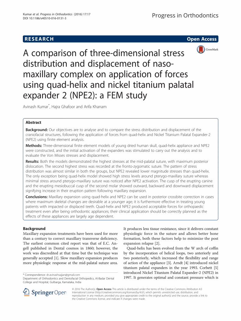
Tetrahedron elements were used to mesh the skull. Quad-helix and NPE2 appliances were modelled by softwareANSYS Design Modeller (Version 16; ANSYS Inc. Inte-grated Design Analysis Consultants) with beam elements(Fig. 1).ANSYS Professional NLS (Version 16; ANSYS Inc.)
was used to carry out the analysis. The total numbers ofelements in the geometry were 864,650, and total numbersof nodes created were 247,119.Thickness of the cortical bone was determined accord-
ing to the study by Farnsworth et al. [7], thickness of peri-odontal ligament was 0.2 mm [8], and the thickness of themaxillofacial and mid-palatal sutures were 0.5 mm [9].
Defining mechanical properties to the model [10–12]The mechanical properties of the tooth, cortical bone,cancellous bone, suture, periodontal ligament, stainlesssteel and nickel titanium in the model were defined ac-cording to the experimental data in previous studies asshown in Table 1.
Laying boundary conditionsThe nodes of the mid-palatal suture element that werecreated in this study were placed on the symmetricalplane and were left unconstrained. Nodes along the for-amen magnum and on the centre of the forehead wereconstrained in all degrees of freedom, with zero displace-ment and zero rotation [13]. The 3D coordinates wereX, transverse plane; Y, sagittal plane; and Z, verticalplane. The midpoint of the lingual alveolar ridge of eachtooth was used as a reference point to evaluate alveolarbone displacement. Positive values indicate outward,backward, and downward displacement on the X, Y, andZ planes, respectively.In this study, a force of 350 g is used in case of NPE2
model as a 3-mm increment of expansion with NiTi pal-atal expander produces 350 g of force [5]. Quad-helixexpansion appliance was activated to one molar width,i.e., around 8 mm. Chaconas [3] reported that an initial8 mm expansion of quad-helix prior to cementation createdapproximately 14 oz (396.89 g) of force which is equivalent
Fig. 1 Schematic representation of the a quad-helix appliance model and b NPE2 appliance model
Kumar et al. Progress in Orthodontics (2016) 17:17 Page 2 of 9

to 3.89 N, and therefore, 2 N of force was applied on eachside. The displacements of maxillofacial complex and VonMisses stresses in different parts were studied. Von Missesis a criteria used in predicting the onset of yield in ductilematerials.
ResultsThe changes seen in the results were divided under twosections
� Displacements of various structures in all the threeplanes produced after the activation of both theappliances
� Von Misses stress distribution over the Naso-maxillarycomplex after the activation of both the appliances
All the maxillofacial structures in the transverse planein both the models showed outward movement exceptfor the lateral nasal wall and the inferior orbital rim. Thelateral nasal wall and inferior orbital rim in both thegroups showed inward, forward and downward movement.Sagittally, all the structure showed forward movement,
except point A, ANS, PNS, maxillary tuberosity, andthe maxillary process of zygomatic bone in both themodels. Vertically in both models, the maxillary tuberosityand all the three process of zygomatic bone showed up-ward movement whereas all the remaining structuresshowed downward displacement. Point A showed out-ward, backward and upward displacement in both themodels (Table 2).As shown in Table 3, both the groups showed opening
of the mid-palatal suture in the transverse direction, andthe maximum amount of dislocation was observed atthe posterior region with high magnitude in quad-helixmodel. The anterior opening of mid-palatal suture wasthe same in both the groups with almost insignificantdifference of displacement between both the groups. Inthe sagittal direction, both the models showed forwardmovement of all mid-palatal suture points, with a grad-ual decrease from the anterior to the posterior areas.Vertically, both the types had a downward movement ofthe mid-palatal suture points (Fig. 2).As shown in Table 4, the amounts of alveolar bone
displacement in both models were greater in the poster-ior than in the anterior areas when viewed in transverseplane. Quad-helix showed more larger amounts of trans-verse expansion compared with NPE2 in the posteriorregion whereas the expansion in the anterior area wasalmost same in both the groups. Sagittally, in both themodels, the alveolar bone at both the anterior and pos-terior area showed forward movement. Vertically, thecusp of the erupting canine showed outward, backwardand extrusive movement similar to the mesiobuccal cuspof the erupting second molar which also showed out-ward, backward and extrusive displacement in both theappliance models.
Table 1 Material property data representation
Young’s modulus(Newton/mm2)
Poisson’s ratio
Tooth [10] 2.07 × 10⁴ 0.30
Cortical bone [10] 1.37 × 10⁴ 0.30
Cancellous bone [10] 7.9 × 10³ 0.30
Suture [10] 7 0.40
Periodontal ligament [10] 50 0.49
Stainless steel [11] 2.1 × 10⁵ 0.3
Nickel titanium [12] 44 × 103 0.33
Table 2 Maxillofacial landmarks displacement (mm) after activation of quad-helix and NPE2
Quad-helix NPE2
X Y Z X Y Z
Point A 0.003427 0.006688 −0.00881 0.003319 0.006248 −0.006096
ANS 0.004253 0.003503 0.008858 0.00391 0.003613 0.006186
PNS 0.005283 0.001837 0.012598 0.005056 0.001094 0.012617
Maxillary tuberosity 0.016233 0.00031 −0.003611 0.013944 0.000208 −0.004822
Pterygoid-hamulus 0.015453 −0.00058 0.00439 0.013264 −0.000674 0.003608
Infra-orbital rim −0.002627 −0.003797 0.002055 −0.003208 −0.004709 0.000064
Frontal process of zygomatic bone 0.005746 −0.003224 −0.0038 0.00482 −0.004307 −0.005211
Maxillary process of zygomatic bone 0.007994 0.001986 −0.004287 0.006796 0.000902 −0.005581
Temporal process of zygomatic bone 0.001178 −0.003673 −0.006246 0.000459 −0.004526 −0.007885
Lateral nasal wall −0.001213 −0.005725 0.004914 −0.001668 −0.006081 0.002756
Inferior nasal floor 0.001095 −0.006938 0.010252 0.000813 −0.006873 0.007878
Lateral pterygoid plate 0.016924 −0.000257 0.001381 0.0145 −0.000456 0.000907
Medial pterygoid plate 0.022838 −0.001301 0.003343 0.020164 −0.001623 0.002856
X transverse, Y sagittal, Z vertical, + indicates outward, backward and downward displacement
Kumar et al. Progress in Orthodontics (2016) 17:17 Page 3 of 9

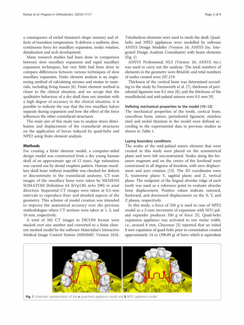
Von Misses stresses as tabulated in Table 5 shows thatthe highest stress was recorded at the mid-palatal suturepoint C in both the models. Quad-helix model exhibitedhigher scale of stresses than did NPE2 model. The stressalong the mid-palatal suture in both the models in-creased from anterior to posterior and then decreasedrapidly near point D, i.e., near palatine bone (Fig. 3).Both the models showed similarity by representing thehighest stress concentration at the fronto-zygomatic su-ture whereas the least stress was experienced at thefronto-maxillary suture. In exception, quad-helix modelshowed high stress levels around pterygo-maxillary su-ture whereas minimal stress around pterygo-maxillarysuture was noticed in NPE2 model. The pattern of stressdistribution was almost similar in both the groups, butNPE2 revealed lower magnitude stresses than quad-helix(Figs. 4, 5, 6, 7 and 8).
DiscussionIn young patients, slow maxillary expansion is said toprovide the maximum rate at which the mid-face suturescan adapt, with minimum tearing and haemorrhagingcompared with rapid maxillary expansion [14–16]. Animal
and histological studies indicate that slow maxillaryexpansion improves conservation of the suture andcan produce a more stable result than rapid maxillaryexpansion [14, 15] Some clinical studies also suggestthat slow maxillary expansion is more stable thanrapid maxillary expansion [16]. Changes in craniofacialskeleton arising from orthodontic treatment are morecomplex than envisaged from two-dimensional cephalo-metric assessments, and so we decided to do a three-dimensional study of the craniofacial skeleton using finiteelement analysis.In the present study, we witnessed skeletal changes
following slow maxillary expansion, similar to thoseHicks [17] had reported; according to him, substantialskeletal changes with slow maxillary expansion can beobserved especially in younger children. The theory isthat the main resistance to the opening of the mid-palatal suture is not the suture itself but the surroundingtissues such as the circum-maxillary structures and mid-face sutures [13]. This observation lends support tostudies that noted the buttressing effect of the zygomaticprocesses against forces of expansion [18] supporting toevidence what we noticed in our study.
Table 3 Mid-palatal suture displacement (mm) after activation of quad-helix and NPE2
Quad-helix NPE2
X Y Z X Y Z
Point A 0.004173 −0.006665 0.008415 0.004138 −0.006013 0.005668
Point B 0.004667 −0.004224 0.012245 0.004367 −0.00415 0.010171
Point C 0.004893 −0.002638 0.012336 0.004564 −0.002295 0.011241
Point D 0.005149 −0.001793 0.012932 0.004922 −0.001159 0.012924
Point A point near incisive foramen, Point D point near palatine bone, Points B and C divide the A–D line into three equal parts, X transverse, Y sagittal, Z vertical, + indicatesoutward, backward and downward displacement
Fig. 2 Pattern of transverse (X) displacement in the maxillary complex after the activation of a quad-helix and b NPE2
Kumar et al. Progress in Orthodontics (2016) 17:17 Page 4 of 9

Orthopaedic force distribution after the activation ofboth the appliances quad-helix and NPE2 were observedto be analogous to what Chaconas and Caputo [19]stated that there was the buttressing of the maxillary tu-berosity with the pterygoid plates; the sphenoid bone
allowed the forces to then radiate to the base of themedial pterygoid plate from this region the forces thenbranched superiorly toward the malar and zygomaticbones. Specifically, the areas of the zygomatico-maxillaryand zygomatico-temporal sutures were affected. Theforces then radiated supero-medially toward the medialwall of the orbit and concentrated at the junction of thenasal and lachrymal bones. From our study, it is evidentthat the maxillary buttresses are the main areas of resist-ance with the forces on the maxillary molars; the stressradiates to the three main buttresses of the mid-face cranialcomplex: the naso-maxillary, the zygomatico-maxillary, andthe pterygo-maxillary [20].Sandikcioglu et al. [21] in his study achieved more
posterior expansion of the palate; however, both themodels in the present study exhibited similar resultsshowing greater posterior dislocation of the mid-palatalsuture than in the anterior region.Our study exhibits downward and forward displace-
ment of maxilla similar to the displacement observed byJafari et al. [22] who studied stress distribution and dis-placement of various craniofacial structures following
Table 4 Dento-alveolar displacement (mm) after activation of quad-helix and NPE2
Quad-helix NPE2
X Y Z X Y Z
Lingual marginal ridge of central incisor 0.005346 −0.005947 0.008094 0.005254 −0.005312 0.00549
Lingual marginal ridge of lateral incisor 0.006913 −0.004625 0.006239 0.006758 −0.004031 0.003674
Lingual marginal ridge of first permanent molar 0.017585 −0.000169 0.003302 0.015673 −0.000006 0.00233
Central incisor cusp tip 0.003598 −0.006677 0.008102 0.003688 −0.005642 0.005067
First permanent molar mesiobuccal cusp tip 0.021027 0.001396 0.005404 0.020318 0.001291 0.007759
Erupting canine cusp tip 0.00872 0.001526 0.005405 0.008523 0.002276 0.001431
Erupting second molar mesiobuccal cusp tip 0.01962 0.000524 0.002048 0.017849 0.000452 0.003237
X transverse, Y sagittal Z vertical, + indicates outward, backward and downward displacement
Table 5 Stress distribution (MPa) at the maxillofacial sutures andlandmarks after activation of the quad-helix and NPE2 appliance
Quad-helix NPE2
Mid-palatal suture
Point A 0.317823 0.317135
Point B 0.969081 0.786962
Point C 2.433233 1.896292
Point D 0.000522 0.00446
Maxillofacial landmarks
Point A 0.434458 0.409881
ANS 0.060478 0.059042
PNS 0.022241 0.01746
Maxillary tuberosity 0.252454 0.189975
Pterygoid hamulua 0.429192 0.375754
Infra-orbital rim 1.029457 0.976392
Frontal process of zygomatic bone 0.502464 0.460146
Maxillary process of zygomatic bone 0.55113 0.509731
Temporal process of zygomatic bone 1.053598 0.9987
Lateral nasal wall 1.219208 1.165219
Inferior nasal floor 0.095343 0.100366
Lateral pterygoid plate 0.21982 0.200389
Fronto-maxillary suture 0.000932 0.000812
Zygomaticomaxillary suture 0.005582 0.005473
Fronto-zygomatic suture 0.075531 0.067953
Fronto-nasal suture 0.020907 0.017968
Zygomatico-temporal suture 0.039584 0.03841
Pterygo-maxillary suture 0.012675 0.007898
Inter-nasal suture 0.06921 0.071998
Naso-maxillary suture 0.002441 0.002493
Point A point near incisive foramen, Point D point near palatine bone, Points Band C divide the A–D line into three equal parts
Fig. 3 Evaluated landmarks: point A, point near incisive foramen;point D, point near palatine bone; point B and C divide the A–D lineinto three equal parts
Kumar et al. Progress in Orthodontics (2016) 17:17 Page 5 of 9

transverse orthopaedic forces. In the present study, wefound backward movement of the point A which can besupported by Wertz [23] and Sandikcioglu et al. [21]who reported that the point A moved slightly backwardand the ANB mostly showed high values. According toWertz research, if it is assumed that point A does notmove forward during rapid maxillary expansion, thechange in the ANB angle could be a result of posteriorrotation of point B [23].During expansion, not all changes are caused by alveo-
lar bending but are partly due to the tipping of teeth inthe alveolar bone; this tipping is usually accompanied bysome extrusion [24]. Similar outcomes were seen in thepresent study where tipping and slight extrusion of themolars were seen. Herold [25] presented greater buccaltipping in a sample treated with quad-helix. Shetty et al.[26] demonstrated tipping and extrusion of teeth follow-ing the use of NPE2.
It is witnessed in the present study that when correctlyemployed, the quad-helix can produce results similar tothe rapid maxillary expansion and also correct all thetransverse problems in the growing patients [14]. In thesame way, NPE2 showed orthopaedic changes when usedin mixed dentition, which is reinforced by the findings ofstudies that NPE2 even though being an orthodontic ap-pliance showed orthopaedic changes [26].The cusp of the erupting canine and the mesiobuccal
cusp of the erupting second molar showed outward,backward and downward displacement indicating thespeeding up for eruption which was similar to study [27]where rapid maxillary expansion was effective in treatingpatients in the late mixed dentition with palatally dis-placed canines. Baccetti et al. [28] stated that maxillaryexpansion is effective as an interceptive procedure toprevent final impaction of maxillary canines with palataldisplacement in the early mixed dentition.
Fig. 4 Stress distribution in the frontal view after activation of the expansion device. a Quad-helix. b NPE2
Fig. 5 Stress distribution in the sagittal view after activation of the expansion device. a Quad-helix. b) NPE2
Kumar et al. Progress in Orthodontics (2016) 17:17 Page 6 of 9
Quad-helix model showed high stress levels aroundpterygo-maxillary suture, whereas the stress levels werevery minimal in NPE2 model which supports the find-ings of Donohue et al. [29] who identified that both thequad-helix and NPE2 were equally efficacious maxillaryexpanders; however, according to them, quad-helix ap-pliance produced more controlled differential expansionbetween the first molars than NPE2 in their clinicalcomparison between the two and so they stated quad-helix more individually predictable in expansion.The results of the present study using three-dimensional
finite element model of a young skull provided explan-ation about the response of appliance activation within thebony tissues; however, finite element method has certainlimitations like the results being applicable to the gener-ated model and may not necessary apply to all individuals;moreover, clinical environment cannot be created in themodel like mastication forces and patient movements;
therefore, the results are for qualitative purpose for em-phasizing skeletal responses of the appliances in humantissues.
ConclusionsQuad-helix and NPE2 produced acceptable forces fororthopaedic treatment even after being an orthodonticappliance; their clinical application should be correctlyplanned as the effects of these appliances are largely agedependent. Both of these appliances can be used alterna-tively in posterior crossbite, where skeletal changes aredesired at a younger age. Quad-helix showed more skeletalexpansion where as NPE2 is proved to be more advan-tageous when dental expansion is desired. Maxillary ex-pansion is furthermore effective in treating patients withimpacted or displaced teeth because of arch length insuffi-ciency during mixed dentition.
Fig. 6 Stress distribution in the lateral view after activation of the expansion device. a Quad-helix. b NPE2
Fig. 7 Stress distribution in the occlusal view after activation of the expansion device. a Quad-helix. b NPE2
Kumar et al. Progress in Orthodontics (2016) 17:17 Page 7 of 9
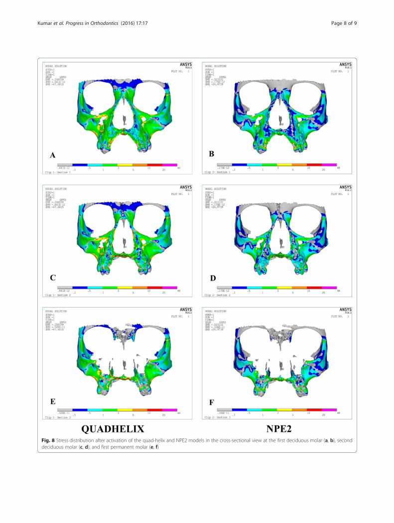
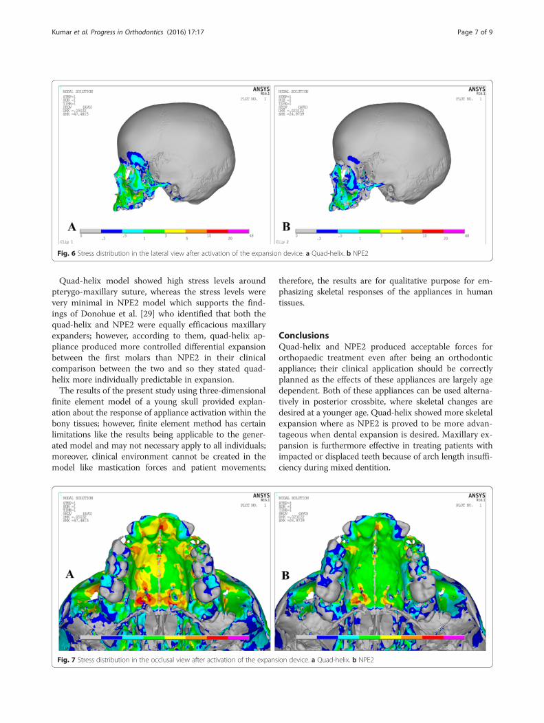
Fig. 8 Stress distribution after activation of the quad-helix and NPE2 models in the cross-sectional view at the first deciduous molar (a, b), seconddeciduous molar (c, d), and first permanent molar (e, f)
Kumar et al. Progress in Orthodontics (2016) 17:17 Page 8 of 9
Although both the appliances produced almost similaramounts of maxillary expansion, from our study, weconclude that the quad-helix treatment regime is consid-ered to be more successful if orthopaedic results areanticipated during mixed dentition period.
Competing interestsThe authors declare that they have no competing interests.
Authors’ contributionsAKu contributed to the study design. AKu, HG and AKh contributed to theliterature search, data acquisition, data analysis, statistical analysis, manuscriptpreparation, manuscript editing and manuscript review. All authors read andapproved the final manuscript.
Received: 4 March 2016 Accepted: 19 May 2016
References1. Timms DJ. The dawn of rapid maxillary expansion. Angle Orthod. 1999;69:247–51.2. Barber AF, Sims MR. Rapid maxillary expansion and external root resorption
in man: a scanning electron microscope study. Am J Orthod. 1981;79:630–52.3. Chaconas SJ, de Alba y Levy JA. Orthopedic and orthodontic applications of
the quad-helix appliance. Am J Orthod. 1977;72:422–8.4. Arndt WV. Nickel titanium palatal expander. J Clin Orthod. 1993;27:129–37.5. Corbett MC. Slow and continuous maxillary expansion, molar rotation and
molar distalization. J Clin Orthod. 1997;4:253–63.6. Srirekha A, Bashetty K. Infinite to finite: an overview of finite element
analysis. Indian J Dent Res. 2010;21:425–32.7. Farnsworth D, Rossouw PE, Ceen RF, Buschang PH. Cortical bone thickness
at common mini-screw implant placement sites. Am J Orthod DentofacOrthop. 2011;139:495–503.
8. Kronfeld R. Histological study of the influence of function on the humanperiodontal membrane. J Am Dent Assoc. 1931;18:1242–74.
9. Fricke-Zech S, Gruber RM, DullinC ZA, Kramer FJ, Meesenburg KD, et al.Measurement of the mid-palatal suture width. Angle Orthod. 2012;82:145–50.
10. Lee NK, Beak SH. Stress and displacement between maxillary protractionwith miniplates placed at the infrazygomatic crest and the lateral nasal wall:a 3-dimensional finite element analysis. Am J Orthod Dentofac Orthop.2012;141:345–51.
11. Tanaka OM, Saga AY, Pithon MM, Argenta MA. Stresses in the mid-palatalsuture in the maxillary protraction therapy: a 3D finite element analysis.Prog Orthod. 2016;17:8.
12. Naceur IB, Charfi A, Bouraoui T, Elleuch K. Finite element modelling ofsuperelastic nickel-titanium orthodontic wires. J Biomechanics. 2014;47:3630–8.
13. Moon W, Wu KW, MacGuiness M, Sung J, Youssef G, Machado A. Theefficacy of maxillary protraction protocols with the micro-implant-assistedrapid palatal expander (MARPE) and the novel N2 mini-implant—a finiteelement study. Prog Orthod. 2015;16:16.
14. Bell RA. The effects of maxillary expansion using a quad-helix applianceduring the deciduous and mixed dentitions. Am J Orthod. 1981;79:152–61.
15. Storey E. Tissue response to the movement of bones. Am J Orthod.1973;64:229–47.
16. Mossaz-Joëlson K, Mossaz CF. Slow maxillary expansion: a comparisonbetween banded and bonded appliances. Eur J Orthod. 1989;11:67–76.
17. Shetty V, Caridad JM, Caputo AA, Chaconas SJ. Biomechanical rationale forsurgical-orthodontic expansion of the adult maxilla. J Oral Maxillofac Surg.1994;52:742–9.
18. Ladner PT, Muhl ZF. Changes concurrent with orthodontic treatment whenmaxillary expansion is a primary goal. Am J Orthod. 1995;108:184–93.
19. Chaconas SJ, Caputo AA. Observation of orthopedic force distributionproduced by maxillary orthodontic appliances. Am J Orthod. 1982;82:492–501.
20. MacGinnis M, Chu H, Youssef G, Wu KW, Machado AW, Moon W. The effectsof micro-implant assisted rapid palatal expansion (MARPE) on thenasomaxillary complex: a finite element method (FEM) analysis. ProgOrthod. 2014;15:52.
21. Sandikcioglu M, Hazar S. Skeletal and dental changes after maxillary expansionin the mixed dentition. Am J Orthod Dentofac Orthop. 1977;111:321–7.
22. Jafari A, Shetty KS, Kumar M. Study of stress distribution and displacementof various craniofacial structures following application of transverse orthopedicforces: a three-dimensional FEM study. Angle Orthod. 2003;73:12–21.
23. Wertz RA. Skeletal and dental changes accompanying rapid mid-palatalsuture opening. Am J Orthod. 1970;58:44–66.
24. Hicks EP. Slow maxillary expansion. A clinical study of the skeletal versusdental response to low-magnitude force. Am J Orthod. 1978;73:121–41.
25. Herold JS. Maxillary expansion: a retrospective study of three methods ofexpansion and their long term sequelae. Br J Orthod. 1989;16:195–200.
26. Shetty P, Hegde AM, Rai K. Study of stress distribution and displacement ofthe maxillary complex following application of forces using jackscrew andnitanium palatal expander 2-A Finite element study. J Clin Paediatric Dent.2009;34:87–93.
27. Sigler LM, Baccetti T, McNamara Jr JA. Effect of rapid maxillary expansionand transpalatal arch treatment associated with deciduous canineextraction on the eruption of palatally displaced canines: a 2-centerprospective study. Am J Orthod Dentofac Orthop. 2011;139:e235–44.
28. Baccetti T, Mucedero M, Leonardi M, Cozza P. Interceptive treatment ofpalatal impaction of maxillary canines with rapid maxillary expansion: arandomized clinical trial. Am J Orthod Dentofac Orthop. 2009;136:657–61.
29. Donohue VE, Marshman LAG, Winchester LJ. A clinical comparison of theQuadhelix appliance and the nickel titanium (tandem loop) palatal expander: aprelimnary prospective investigation. Eur J Orthod. 2004;26:411–20.
Submit your manuscript to a journal and benefi t from:
7 Convenient online submission
7 Rigorous peer review
7 Immediate publication on acceptance
7 Open access: articles freely available online
7 High visibility within the fi eld
7 Retaining the copyright to your article
Submit your next manuscript at 7 springeropen.com
Kumar et al. Progress in Orthodontics (2016) 17:17 Page 9 of 9