
A COMPARISON OF SEVERAL SELF-STRUCTURING ANTENNA …
34
A COMPARISON OF SEVERAL SELF-STRUCTURING ANTENNA TEMPLATES B. T. Perry*, J.A. Nanzer J. E. Ross L.L. Nagy and E.J. Rothwell John Ross & Associates Delphi Research Labs ECE Department 422 N. Chicago Street 51786 Shelby Pkwy Michigan State University Salt Lake City, Utah Shelby Township, MI East Lansing, MI 48824 [email protected] [email protected] Successful operation of a self-structuring antenna (SSA) depends both on the large number of available antenna states, and the underlying characteristics of the antenna template. For example, if an antenna template is too small, an SSA likely won’t perform well for low frequency applications, regardless of the switch states. Another possibility is that an SSA template is of appropriate size; in this case, the performance of the antenna depends on both the switch states and the configuration of the antenna elements. Up to this point, the effect of the underlying characteristics of the antenna template, i.e., the configuration of the antenna elements, has not been thoroughly studied. This paper looks to characterize the effect of the SSA template layout, using measured data such as standing wave ratio (SWR), antenna patterns, and input impedance. By finding the effect of template layout on the performance of the SSA, guidelines can be created by which future layouts can be designed. Through this process, self- structuring antenna templates can be custom designed to better fit particular applications. This paper uses measured performance criteria to compare and contrast several SSA template designs. These designs include a “standard”, linearly spaced SSA template, as described in previous work, a variation based on a log-periodic design, and several templates that are fairly application specific. The application specific templates are configured such that all switches and control hardware are aligned along one edge of the template. This allows the SSA to be used in applications where the placement of both the feed network and the switches are desired to be hidden away.
Transcript of A COMPARISON OF SEVERAL SELF-STRUCTURING ANTENNA …

A COMPARISON OF SEVERAL SELF-STRUCTURING ANTENNATEMPLATES
B. T. Perry*, J.A. Nanzer J. E. Ross L.L. Nagyand E.J. Rothwell John Ross & Associates Delphi Research LabsECE Department 422 N. Chicago Street 51786 Shelby PkwyMichigan State University Salt Lake City, Utah Shelby Township, MIEast Lansing, MI 48824 [email protected]@egr.msu.edu
Successful operation of a self-structuring antenna (SSA) depends both on thelarge number of available antenna states, and the underlying characteristics of theantenna template. For example, if an antenna template is too small, an SSA likelywon’t perform well for low frequency applications, regardless of the switch states.Another possibility is that an SSA template is of appropriate size; in this case, theperformance of the antenna depends on both the switch states and theconfiguration of the antenna elements. Up to this point, the effect of theunderlying characteristics of the antenna template, i.e., the configuration of theantenna elements, has not been thoroughly studied. This paper looks tocharacterize the effect of the SSA template layout, using measured data such asstanding wave ratio (SWR), antenna patterns, and input impedance. By findingthe effect of template layout on the performance of the SSA, guidelines can becreated by which future layouts can be designed. Through this process, self-structuring antenna templates can be custom designed to better fit particularapplications.
This paper uses measured performance criteria to compare and contrast severalSSA template designs. These designs include a “standard”, linearly spaced SSAtemplate, as described in previous work, a variation based on a log-periodicdesign, and several templates that are fairly application specific. The applicationspecific templates are configured such that all switches and control hardware arealigned along one edge of the template. This allows the SSA to be used inapplications where the placement of both the feed network and the switches aredesired to be hidden away.

A COMPARISON OF SEVERAL SELF-STRUCTURING ANTENNATEMPLATES
B. T. Perry*, J.A. Nanzer J. E. Ross L.L. Nagyand E.J. Rothwell John Ross & Associates Delphi Research LabsECE Department 422 N. Chicago Street 51786 Shelby PkwyMichigan State University Salt Lake City, Utah Shelby Township, MIEast Lansing, MI 48824 [email protected]@egr.msu.edu
1. Commission and session topic: B1.1 Antenna Analysis and Design
2. Required presentation equipment: PowerPoint display
3. Corresponding author:Edward J. RothwellDepartment of Electrical and Computer EngineeringMichigan State UniversityEast Lansing, MI 48824Phone: 517-355-5231e-mail: [email protected]: 517-353-1980
6. New knowledge contributed by paper: This is the first comprehensivecomparison of differing self-structuring antenna template designs utilizing measureddata.
7. Relationship to previous work: Self-structuring antennas were introduced bythe authors at the 2000, 2001, and 2002 URSI National Radio Science Meetings.The basic operation and analysis of the antenna were described in these papers.
A Comparison of Several SSA Templates 1June 24, 2003
A Comparison of Several Self-StructuringAntenna Templates
URSI B Session 56Tuesday June 24, 8:20 am, Knox
MSU EM Group
B.T. Perry, J.A. Nanzer*, E.J. Rothwell, L.C. KempelMichigan State University
J.E. Ross, John Ross and AssociatesL.L. Nagy, Delphi Research Labs
A Comparison of Several SSA Templates 2June 24, 2003
Overview of Presentation
• Introduction to Self-Structuring Antennas (SSAs)• Description of templates• Measured SWR results• Measured pattern results• Conclusions
A Comparison of Several SSA Templates 3June 24, 2003
Self-Structuring AntennaConcept
• Self-Structuring Antenna system:
o Re-optimizes itself when its electromagnetic environment changes
o Arranges itself into a large number of possible antenna configurations
o Uses information from a receiver or sensor to determine fitness of eachconfiguration and determines future configurations
o Searches through possible configurations using binary search routine such as;Genetic algorithms (GAs)Simulated annealing (SA)Ant colony optimization (ACO)
A Comparison of Several SSA Templates 4June 24, 2003
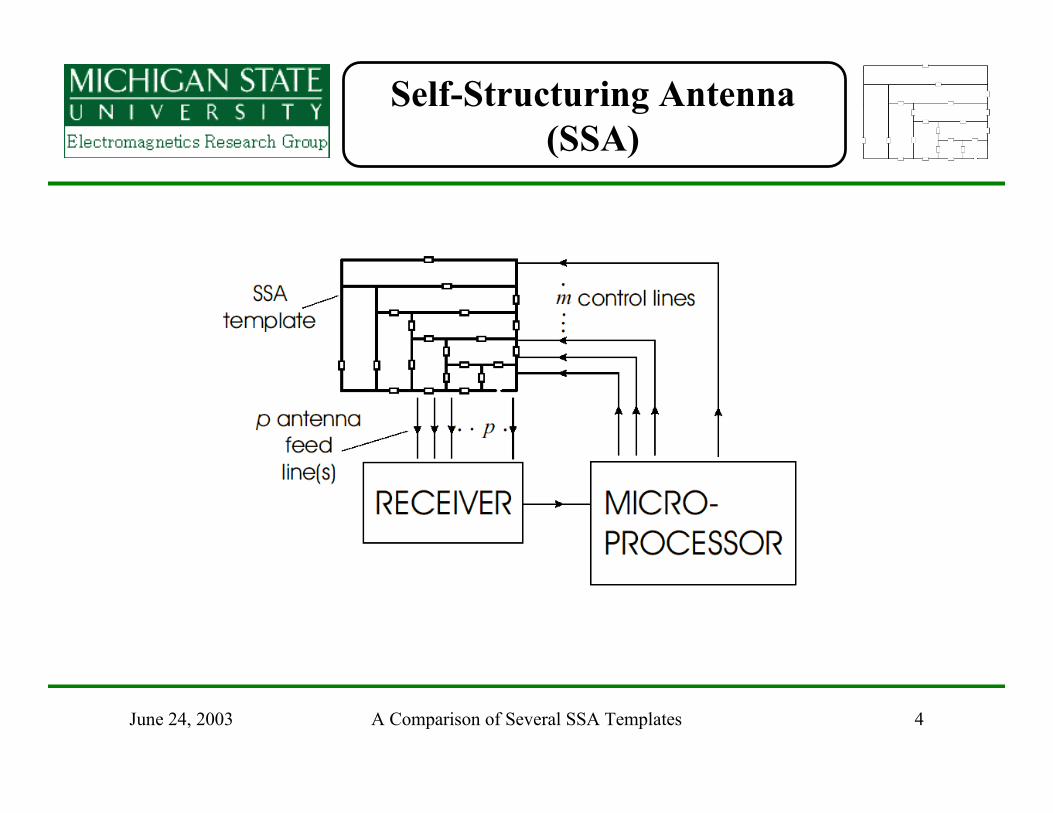
Self-Structuring Antenna(SSA)
A Comparison of Several SSA Templates 5June 24, 2003
Self-Structuring AntennaTemplate
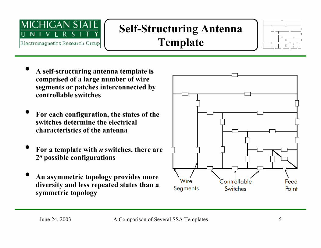
• A self-structuring antenna template iscomprised of a large number of wiresegments or patches interconnected bycontrollable switches
• For each configuration, the states of theswitches determine the electricalcharacteristics of the antenna
• For a template with n switches, there are2n possible configurations
• An asymmetric topology provides morediversity and less repeated states than asymmetric topology

A Comparison of Several SSA Templates 6June 24, 2003
Templates studied
• Four different templates were studied
o “Standard” templateo Log-periodic designo Edge-switch template 1o Edge-switch template 2
• Templates with switches located along the edge may prove moreuseful for automotive applications
• Templates with switches concentrated near the feed may be lessaffected by switch failures

A Comparison of Several SSA Templates 7June 24, 2003
Templates studied
• “Standard”template
• 32 switches =4.3 billioncombinations
• 16`` x 22``

A Comparison of Several SSA Templates 8June 24, 2003
Templates studied
• Log-periodictemplate
• 32 switches
• 16`` x 22``

A Comparison of Several SSA Templates 9June 24, 2003
Templates studied
• Edge-switchedType 1
• 32 switches
• 16`` x 22``

A Comparison of Several SSA Templates 10June 24, 2003
Templates studied
• Edge-switchedType 2
• 32 switches
• 16`` x 22``

A Comparison of Several SSA Templates 11June 24, 2003
SWR measurements
• Experimental setup
• Measure 30,000independent antennastates
• Look at statisticaldistribution of SWRvalues
• SWR calculatedrelative to 200ΩΩΩΩ

A Comparison of Several SSA Templates 12June 24, 2003
SWR measurements
1.0 2.0 3.01.1 1.2 1.3 1.4 1.5 1.6 1.7 1.8 1.9 2.1 2.2 2.3 2.4 2.5 2.6 2.7 2.8 2.9
SWR
0.01
0.1
1
10
100
0.020.030.040.050.07
0.20.30.40.50.7
23457
2030405070
% o
f sta
tes
at o
r bel
ow S
WR
error bars show 95% confidence interval
50 MHz
S
E1
E2L
Standard
Log-periodic

A Comparison of Several SSA Templates 13June 24, 2003
SWR measurements
1.0 2.0 3.01.1 1.2 1.3 1.4 1.5 1.6 1.7 1.8 1.9 2.1 2.2 2.3 2.4 2.5 2.6 2.7 2.8 2.9
SWR
0.01
0.1
1
10
100
0.020.030.040.050.07
0.20.30.40.50.7
23457
2030405070
% o
f sta
tes
at o
r bel
ow S
WR
error bars show 95% confidence interval
100 MHz
SE1 E2
L
Edge 1
Edge 2

A Comparison of Several SSA Templates 14June 24, 2003
SWR measurements
1.0 2.0 3.01.1 1.2 1.3 1.4 1.5 1.6 1.7 1.8 1.9 2.1 2.2 2.3 2.4 2.5 2.6 2.7 2.8 2.9
SWR
0.01
0.1
1
10
100
0.020.030.040.050.07
0.20.30.40.50.7
23457
2030405070
% o
f sta
tes
at o
r bel
ow S
WR
error bars show 95% confidence interval
150 MHz
S E1E2
L

A Comparison of Several SSA Templates 15June 24, 2003
SWR measurements
1.0 2.0 3.01.1 1.2 1.3 1.4 1.5 1.6 1.7 1.8 1.9 2.1 2.2 2.3 2.4 2.5 2.6 2.7 2.8 2.9
SWR
0.01
0.1
1
10
100
0.020.030.040.050.07
0.20.30.40.50.7
23457
2030405070
% o
f sta
tes
at o
r bel
ow S
WR
error bars show 95% confidence interval
300 MHz
SE1
E2
L
A Comparison of Several SSA Templates 16June 24, 2003
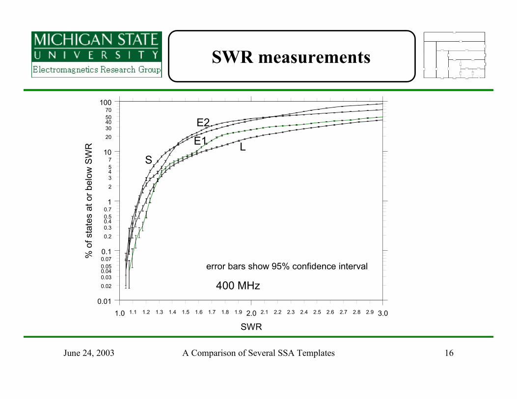
SWR measurements
1.0 2.0 3.01.1 1.2 1.3 1.4 1.5 1.6 1.7 1.8 1.9 2.1 2.2 2.3 2.4 2.5 2.6 2.7 2.8 2.9
SWR
0.01
0.1
1
10
100
0.020.030.040.050.07
0.20.30.40.50.7
23457
2030405070
% o
f sta
tes
at o
r bel
ow S
WR
error bars show 95% confidence interval
400 MHz
S
E1E2
L

A Comparison of Several SSA Templates 17June 24, 2003
SWR measurements
1.0 2.0 3.01.1 1.2 1.3 1.4 1.5 1.6 1.7 1.8 1.9 2.1 2.2 2.3 2.4 2.5 2.6 2.7 2.8 2.9
SWR
0.01
0.1
1
10
100
0.020.030.040.050.07
0.20.30.40.50.7
23457
2030405070
% o
f sta
tes
at o
r bel
ow S
WR
error bars show 95% confidence interval
500 MHz
SE1
E2
L

A Comparison of Several SSA Templates 18June 24, 2003
SWR measurements
1.0 2.0 3.01.1 1.2 1.3 1.4 1.5 1.6 1.7 1.8 1.9 2.1 2.2 2.3 2.4 2.5 2.6 2.7 2.8 2.9
SWR
0.01
0.1
1
10
100
0.020.030.040.050.07
0.20.30.40.50.7
23457
2030405070
% o
f sta
tes
at o
r bel
ow S
WR
error bars show 95% confidence interval
600 MHz
SE1E2
L
Standard
Log-periodic

A Comparison of Several SSA Templates 19June 24, 2003
SWR measurements
1.0 2.0 3.01.1 1.2 1.3 1.4 1.5 1.6 1.7 1.8 1.9 2.1 2.2 2.3 2.4 2.5 2.6 2.7 2.8 2.9
SWR
0.01
0.1
1
10
100
0.020.030.040.050.07
0.20.30.40.50.7
23457
2030405070
% o
f sta
tes
at o
r bel
ow S
WR
error bars show 95% confidence interval
700 MHz
E1
E2
L
Edge 1
Edge 2
A Comparison of Several SSA Templates 20June 24, 2003
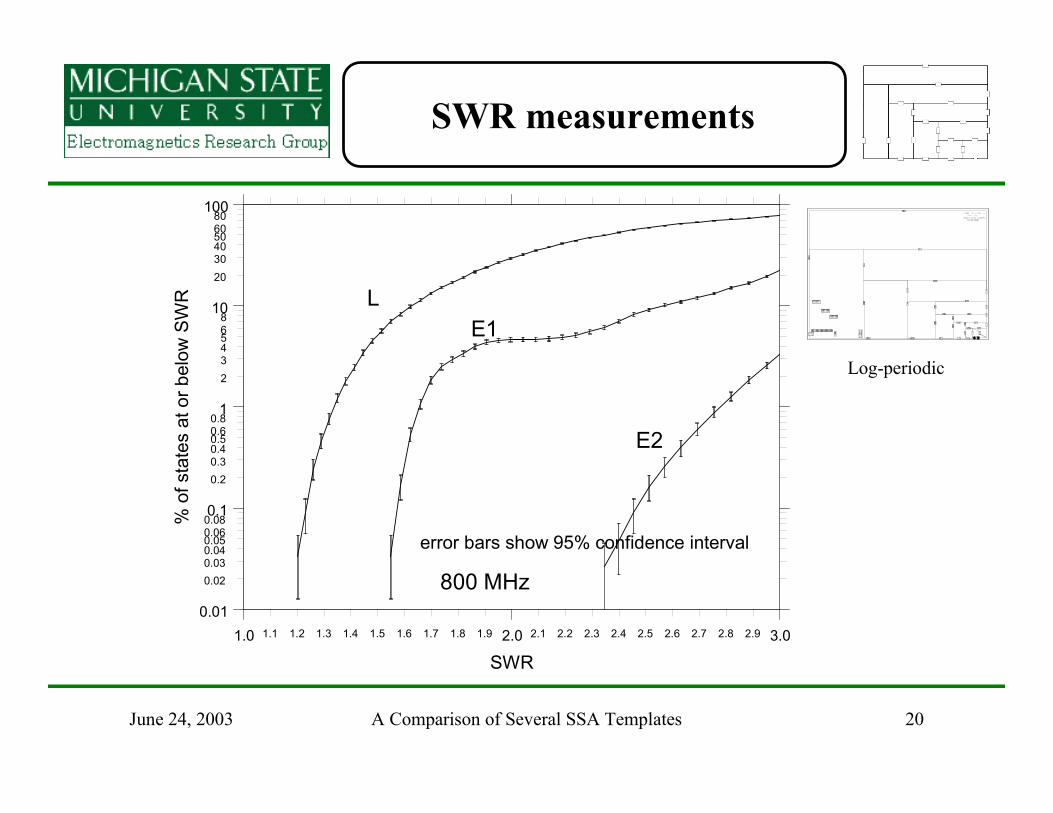
SWR measurements
1.0 2.0 3.01.1 1.2 1.3 1.4 1.5 1.6 1.7 1.8 1.9 2.1 2.2 2.3 2.4 2.5 2.6 2.7 2.8 2.9
SWR
0.01
0.1
1
10
100
0.020.030.040.050.060.08
0.20.30.40.50.60.8
234568
203040506080
% o
f sta
tes
at o
r bel
ow S
WR
error bars show 95% confidence interval
800 MHz
E1
E2
L
Log-periodic
A Comparison of Several SSA Templates 21June 24, 2003
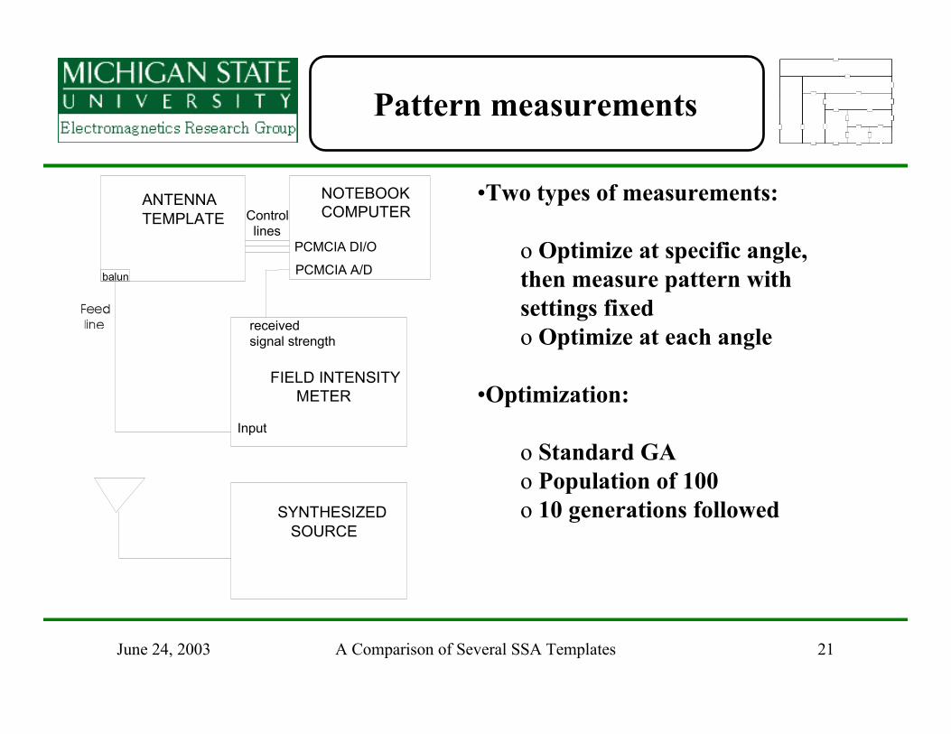
Pattern measurements
•Two types of measurements:
o Optimize at specific angle,then measure pattern withsettings fixedo Optimize at each angle
•Optimization:
o Standard GAo Population of 100o 10 generations followed
Control lines
PCMCIA DI/O
PCMCIA A/Dbalun
ANTENNATEMPLATE
SYNTHESIZED SOURCE
NOTEBOOKCOMPUTER
FIELD INTENSITY METER
receivedsignal strength
Input

A Comparison of Several SSA Templates 22June 24, 2003
Pattern measurements
o Reference angle setup (view looking down)
Transmittingantenna
SSA
Zero deg 90 deg
Front of SSA
Transmittingantenna
Front of SSA

A Comparison of Several SSA Templates 23June 24, 2003
Pattern measurements
Standard template 400 MHz vertical polarization
optimized at every angleoptimized at zero deg
0
90

A Comparison of Several SSA Templates 24June 24, 2003
Pattern measurements
Standard template 400 MHz horizontal polarization
optimized at every angleoptimized at zero deg
0
90

A Comparison of Several SSA Templates 25June 24, 2003
Pattern measurements
Edge Type 1 template 400 MHz vertical polarization
optimized at every angleoptimized at zero deg
0
90

A Comparison of Several SSA Templates 26June 24, 2003
Pattern measurements
Edge Type 1 template 400 MHz vertical polarization
optimized at 90 degoptimized at 180 degoptimized at 270 deg
0
90

A Comparison of Several SSA Templates 27June 24, 2003
Pattern measurements
Edge Type 1 template 400 MHz horizontal polarization
optimized at every angleoptimized at zero deg
0
90

A Comparison of Several SSA Templates 28June 24, 2003
Pattern measurements
Edge Type 2 400 MHz vertical polarization
optimized at every angleoptimized at zero deg
0
90

A Comparison of Several SSA Templates 29June 24, 2003
Pattern measurements
Edge Type 2 template 400 MHz horizontal polarization
optimized at every angleoptimized at zero deg
0
90

A Comparison of Several SSA Templates 30June 24, 2003
Pattern measurements
Log-periodic 400 MHz vertical polarization
optimized at every angleoptimized at zero deg
0
90

A Comparison of Several SSA Templates 31June 24, 2003
Pattern measurements
Log-periodic 400 MHz horizontal polarization
optimized at every angleoptimized at zero deg
0
90

A Comparison of Several SSA Templates 32June 24, 2003
Conclusions
• SWRo Type 1 Edge-switched template has performance equal to
Standard designo Type 2 Edge-switched template has performance inferior to edge-
switched Type 1 design at most frequencieso Log-periodic design has poorer low-frequency performance, but
superior high-frequency performance
• Patternso All templates work well when optimized at all angleso Pattern can be steered to some extent by optimizing in a specific
direction