A Comparative Performance analysis of ENERCON 3MW E-82 E3 ... Issue 3... · Akshay N.Deshmukh1,...
7
IOSR Journal of Electrical and Electronics Engineering (IOSR-JEEE) e-ISSN: 2278-1676,p-ISSN: 2320-3331, Volume 12, Issue 3 Ver. I (May. – June. 2017), PP 35-41 www.iosrjournals.org DOI: 10.9790/1676-1203013541 www.iosrjournals.org 35 | Page A Comparative Performance analysis of ENERCON 3MW E-82 E3 Wind Generator for Vijaydurg, Chalkewadi and Pachgani location of Maharashtra, India Akshay N.Deshmukh 1 , Akshay D. Kadu 2 , Rajesh T Rane 3 1,2,3 Dept. of Electrical Engg. Rajiv Gandhi College of ERngg. Reseaerch, Nagpur Abstract: ENERCON manufacturer-specific Units of wind turbines are favoured for use in wind power interconnection studies. Certain manufacturer specifications are mentioned in datasheet like Wind Power curve, Power coefficient (Cp), Rated Power, rotor diameter, Hub height Swept area, Cut in, rated and cut-out Wind velocities. The primary objective of the work is to perform comparative performance analysis of ENERCON 3MW E-82 E3 Wind Generator for Vijaydurg, Chalkewadi and Pachgani location of Maharashtra.Wind Power Output under variable speed condition, actual power developed by wind generator, power coefficient (Cp), Power developed by rotor (Pr) and aerodynamic torque developed by wind turbine is calculated on the basis of mathematical modelling of Wind generator in Matlab. The best suitability ofENERCON 3MW E-82 E3 Wind Generator is evaluated on above mentioned performance indices for the locations detailed above. Keywords: Power coefficient (Cp),Power developed by rotor (Pr), Wind Energy Conversion System (WECS), Hourly Mean Wind Speed(HMWS) I. Introduction A quick glance at the electrification world map will show that rural areas are in great need of affordable and reliable electricity to achieve development. Likewise, an overview through the most important literature on rural electrification will prove that renewable energies (RES) are one of the most suitable and environ-mentally friendly solutions to provide electricity within rural areas. Over the last years the wind systems became the fastest developing renewable energy technology. There are three main factors which determine the power output of a whole wind energy conversion system (WECS), i.e., the Wind Power Curve of a chosen wind turbine, the wind speed distribution of a selected site where the wind turbine is to be installed, the hub height of the wind tower, power coefficient (Cp), Power developed by rotor (Pr) and aerodynamic torque. Wind turbine power production depends on interaction between the wind turbine rotor and the wind. The mean power output is determined by the mean wind speed, thus only steady-state aerodynamics has been considered and turbulence has been ignored. The first aerodynamic analyses of wind turbines were carried out by Betz and Glauert in the late 1920s and early 1930s. Betz proved that the maximum power extractable by an ideal turbine rotor with infinite blades from wind under ideal conditions is 59.26% (0.5926 times) of the power available in the wind. This limit is known as the Betz limit.The ratio of extractable power to available power is expressed as the rotor power coefficient Cp.The tip-speed ratio or TSR, denoted by λ, is the ratio of the blade-tip linear speed to the wind speed. The impact of all the above parameters on the performance of ENERCON 3MW E-82 E3 Wind Generator for Vijaydurg, Chalkewadi and Pachgani location of Maharashtra is analysed thoroughly in this paper considering the wind speed data for these locations and mathematical equations pertaining to Wind Power Generation dynamics. II. Enerocon Turbine Technology ENERCON’s rotor blade concept has set new standards in the wind energy sector. Due to their modified shape, the blades not only draw energy from the outer edges of the swept area but also make more efficient use of the inner radius considerably increasing power output. The new rotor blades are also less susceptible to turbulence and provide an even flow of air along the entire length of the blade profile. The blade tips have also been improved to reduce noise emission and increase power output. Turbulence at the blade tips caused by over and under pressure is effectively eliminated in the rotor plane. The entire length of the blade is therefore utilised without energy loss resulting from turbulence. In order to withstand extreme wind loads during the entire lifespan of the machine, ENERCON rotor blades are engineered with a large flange root. The double- row bolt connection specially developed by ENERCON for large wind turbines also provides additional strength by creating even load distribution. The safety of turbines with longer rotor blades is further enhanced by sensors at the blade root, enabling the turbine to react to extreme loads. These are important factors, particularly in locations with extreme wind and considerable load fluctuations. ENERCON rotor blades are manufactured
Transcript of A Comparative Performance analysis of ENERCON 3MW E-82 E3 ... Issue 3... · Akshay N.Deshmukh1,...
IOSR Journal of Electrical and Electronics Engineering (IOSR-JEEE)
e-ISSN: 2278-1676,p-ISSN: 2320-3331, Volume 12, Issue 3 Ver. I (May. – June. 2017), PP 35-41
www.iosrjournals.org
DOI: 10.9790/1676-1203013541 www.iosrjournals.org 35 | Page
A Comparative Performance analysis of ENERCON 3MW E-82
E3 Wind Generator for Vijaydurg, Chalkewadi and Pachgani
location of Maharashtra, India
Akshay N.Deshmukh1, Akshay D. Kadu
2, Rajesh T Rane
3
1,2,3 Dept. of Electrical Engg. Rajiv Gandhi College of ERngg. Reseaerch, Nagpur
Abstract: ENERCON manufacturer-specific Units of wind turbines are favoured for use in wind power
interconnection studies. Certain manufacturer specifications are mentioned in datasheet like Wind Power curve,
Power coefficient (Cp), Rated Power, rotor diameter, Hub height Swept area, Cut in, rated and cut-out Wind
velocities. The primary objective of the work is to perform comparative performance analysis of ENERCON
3MW E-82 E3 Wind Generator for Vijaydurg, Chalkewadi and Pachgani location of Maharashtra.Wind Power
Output under variable speed condition, actual power developed by wind generator, power coefficient (Cp),
Power developed by rotor (Pr) and aerodynamic torque developed by wind turbine is calculated on the basis of
mathematical modelling of Wind generator in Matlab. The best suitability ofENERCON 3MW E-82 E3 Wind
Generator is evaluated on above mentioned performance indices for the locations detailed above.
Keywords: Power coefficient (Cp),Power developed by rotor (Pr), Wind Energy Conversion System (WECS),
Hourly Mean Wind Speed(HMWS)
I. Introduction A quick glance at the electrification world map will show that rural areas are in great need of
affordable and reliable electricity to achieve development. Likewise, an overview through the most important
literature on rural electrification will prove that renewable energies (RES) are one of the most suitable and
environ-mentally friendly solutions to provide electricity within rural areas.
Over the last years the wind systems became the fastest developing renewable energy technology.
There are three main factors which determine the power output of a whole wind energy conversion system
(WECS), i.e., the Wind Power Curve of a chosen wind turbine, the wind speed distribution of a selected site
where the wind turbine is to be installed, the hub height of the wind tower, power coefficient (Cp), Power
developed by rotor (Pr) and aerodynamic torque.
Wind turbine power production depends on interaction between the wind turbine rotor and the wind.
The mean power output is determined by the mean wind speed, thus only steady-state aerodynamics has been
considered and turbulence has been ignored. The first aerodynamic analyses of wind turbines were carried out
by Betz and Glauert in the late 1920s and early 1930s. Betz proved that the maximum power extractable by an
ideal turbine rotor with infinite blades from wind under ideal conditions is 59.26% (0.5926 times) of the power
available in the wind. This limit is known as the Betz limit.The ratio of extractable power to available power is
expressed as the rotor power coefficient Cp.The tip-speed ratio or TSR, denoted by λ, is the ratio of the blade-tip
linear speed to the wind speed. The impact of all the above parameters on the performance of ENERCON 3MW
E-82 E3 Wind Generator for Vijaydurg, Chalkewadi and Pachgani location of Maharashtra is analysed
thoroughly in this paper considering the wind speed data for these locations and mathematical equations
pertaining to Wind Power Generation dynamics.
II. Enerocon Turbine Technology ENERCON’s rotor blade concept has set new standards in the wind energy sector. Due to their
modified shape, the blades not only draw energy from the outer edges of the swept area but also make more
efficient use of the inner radius considerably increasing power output. The new rotor blades are also less
susceptible to turbulence and provide an even flow of air along the entire length of the blade profile. The blade
tips have also been improved to reduce noise emission and increase power output. Turbulence at the blade tips
caused by over and under pressure is effectively eliminated in the rotor plane. The entire length of the blade is
therefore utilised without energy loss resulting from turbulence. In order to withstand extreme wind loads during
the entire lifespan of the machine, ENERCON rotor blades are engineered with a large flange root. The double-
row bolt connection specially developed by ENERCON for large wind turbines also provides additional strength
by creating even load distribution. The safety of turbines with longer rotor blades is further enhanced by sensors
at the blade root, enabling the turbine to react to extreme loads. These are important factors, particularly in
locations with extreme wind and considerable load fluctuations. ENERCON rotor blades are manufactured

A Comparative Performance analysis of ENERCON 3MW E-82 E3 Wind Generator for
DOI: 10.9790/1676-1203013541 www.iosrjournals.org 36 | Page
using a vacuum infusion system and the so-called sandwich technique. In a final step, the rotor blades are
finished with a special coating in order to efficiently protect their surface from weathering.
III. Enercon Direct Drive System Fewer rotating parts reduce mechanical stress and increase the machine ́s lifespan . Wind turbinemaintenance
and service
Fig.1:Cross Sectional view of Wind Generator
costs are reduced (fewer wearing parts, no gear oil change, etc.) and operating expenses lowered. The rotor hub
and the rotor of the annular generator are directly interconnected to form one consolidated unit. The rotor unit is
mounted on a fixed axis, the so-called axle pin. Unlike conventional geared systems with a large number of
bearing points in a moving drive train, ENERCON’s drive system only requires two slow-moving rolling-
element bearings; the reason being its low direct drive speed
Fig.2: Magnified View of Stator Winding
IV. Annular Generator Technology Amongst other features, the annular generator is a key component in ENERCON’s gearless wind
generator design. Combined with the rotor hub, it provides an almost frictionless flow of energy, while a smaller
number of moving components ensure minimum material wear. Unlike conventional fast-running generators,
ENERCON’s annular generator is subjected to little mechanical wear, making it ideal for particularly heavy
loads and guaranteeing a long service life. It is a low-speed synchronous generator with no direct grid coupling.
Output voltage and frequency vary with the speed and are converted for output to the grid via a DC link and
inverter which allow for high speed variability.
Stator and rotor:
According to ENERCON’s service life requirements, the copper winding in the stator (the stationary
part of the annular generator) is produced in insulation class F (155 °C). Because this resembles basket weaving,
it is also called closed, single-layer basket weaving. It consists of individual varnish-insulated round wires
gathered together in bundles. At ENERCON, the copper winding is exclusively done by hand. In spite of
increasing automation in other manufacturing areas, there is a good reason for relying on manual labour in this
instance. It ensures that all materials are thoroughly inspected. Furthermore, a special work process allows
continuous windings to be produced. Each individual wire strand is continuous from start to end. ENERCON
wind energy converters are based on a gearless turbine design that uses an annular generator with separates
A Comparative Performance analysis of ENERCON 3MW E-82 E3 Wind Generator for
DOI: 10.9790/1676-1203013541 www.iosrjournals.org 37 | Page
excitation. The magnetic fields required to generate electrical power are created electrically, so permanent
magnets containing the controversial rare earth element neodymium can be dispensed with. The magnetic field
of the stator winding is excited by means of the so-called pole shoes. These are on the rotor – the rotating part of
ENERCON´s annular generator. Since the shape and position of the pole shoes have a decisive influence on the
generator’s noise emission, ENERCON´s Research & Development department has devoted particular attention
to this aspect. Because the pole shoes are precisely adapted to the slow rotation of ENERCON’s annular
generator, there is virtually no tonal noise.
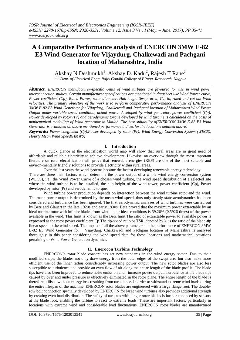
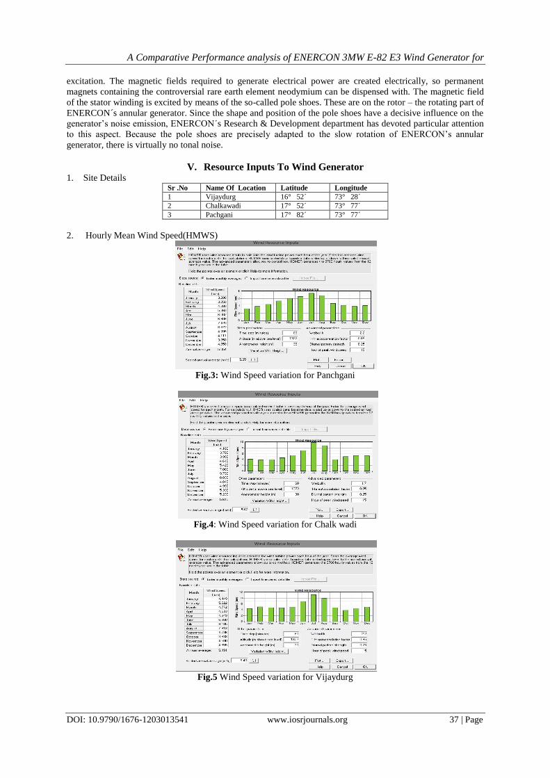
V. Resource Inputs To Wind Generator 1. Site Details
Sr .No Name Of Location Latitude Longitude
1 Vijaydurg 16° 52´ 73° 28´
2 Chalkawadi 17° 52´ 73° 77´
3 Pachgani 17° 82´ 73° 77´
2. Hourly Mean Wind Speed(HMWS)
Fig.3: Wind Speed variation for Panchgani
Fig.4: Wind Speed variation for Chalk wadi
Fig.5 Wind Speed variation for Vijaydurg

A Comparative Performance analysis of ENERCON 3MW E-82 E3 Wind Generator for
DOI: 10.9790/1676-1203013541 www.iosrjournals.org 38 | Page
3. 2. ENERCON 3MW E-82 E3 WIND GENERATOR SPECIFICATIONS Specifications Ratings
Rated Power 3MW
Rotor diameter 82m
Hub Height 78m/85m/98m/108m/138m
Swept Area 5281 sq.m
Rotational Speed 6-18.5rpm
Cutout Wind Speed 28-34 m/sec
VI. Mathamatical Modelling Equations
v t = vr t . (h
hr)γ (i)
Where:
• v is the wind speed at projected height h,
• vr is wind speed at reference height hr ,
• γ is the power-law exponent (~1/7 for open land).
• In function of this wind speed, the model used to calculate the output power, PWT(t) (W), generated by the
wind turbine generator is as follows:
a. v3 t − b. PR vci < 𝑣 < vr (ii)
PWT t = PR vr < 𝑣 < 𝑣𝑐0 (iii)
Where,
a = Pr
(v³r−v³ci ) (iv)
b = v³ci
(v³r−v³ci ) (v)
Pr is the ratedpower, vci, vr and vcoare respectively the cut-in, rated and cutout wind speed of the wind turbine.
Pactual = PWT t ∗ Aw ∗ eff (vi)
Pactual-Actual Power generated
PWT t − RatedPowerofWindGenertor
Aw-Swept Area (in Sq.m)
λ =ωrotor .R rottor
Vwind (vii)
ωrotor . - Angular velocity of wind Turbine
Rrotor - Rotor radius in m
Vwind − Wind velocity in m/sec During the analysis, beta is varied from 1 to 13 and angular velocity is varied from 6m/sec to 18m/sec
λi=
1
λ+ 0.08∗β −
0.035
β3 +1
(viii)
λi1=
1
λi
(ix)
Cp=0.22∗exp(−12.5
λi1) ∗ (
116
λi1− 0.4 ∗ β − 5) (x)
Where,
β - Blade pitch angle
λ -Tip Speed ratio
Cp -Power Coefficient
Protor = 0.5 ∗ ρ ∗ Cp ∗ π ∗ Rrotor2 ∗ v3
AerodynamicTorque =Protor
ωrotor (xi)
A Comparative Performance analysis of ENERCON 3MW E-82 E3 Wind Generator for
DOI: 10.9790/1676-1203013541 www.iosrjournals.org 39 | Page
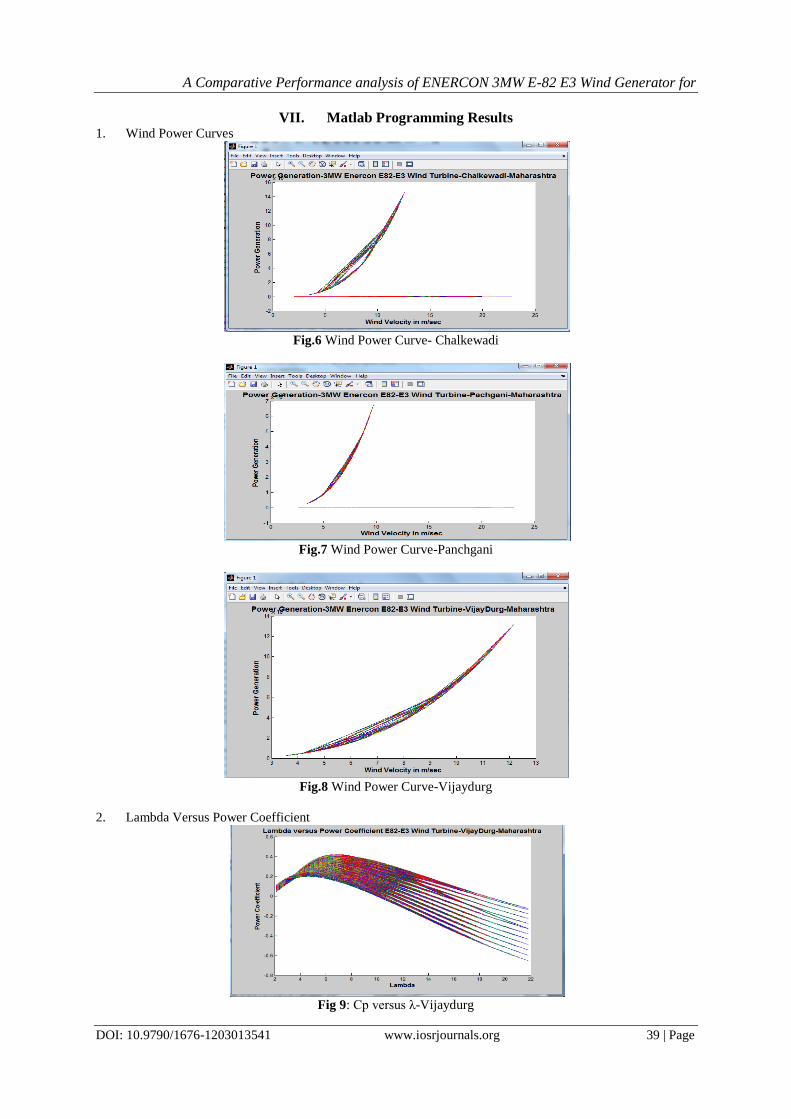
VII. Matlab Programming Results 1. Wind Power Curves
Fig.6 Wind Power Curve- Chalkewadi
Fig.7 Wind Power Curve-Panchgani
Fig.8 Wind Power Curve-Vijaydurg
2. Lambda Versus Power Coefficient
Fig 9: Cp versus λ-Vijaydurg

A Comparative Performance analysis of ENERCON 3MW E-82 E3 Wind Generator for
DOI: 10.9790/1676-1203013541 www.iosrjournals.org 40 | Page
Fig.10: Cp versus λ-Panchgani
Fig.11: Cp versus λ- Chalkewadi
3. Wind Velocity Versus Aerodynamic Torque
Fig.12:V versus Aerodynamic Torque-Chalkewadi
Fig.13: V versus Aerodynamic Torque-Panchgani
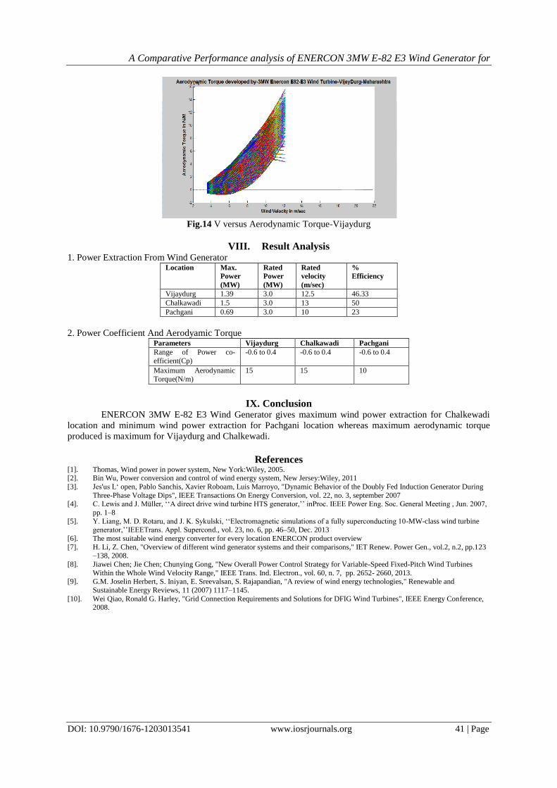
A Comparative Performance analysis of ENERCON 3MW E-82 E3 Wind Generator for
DOI: 10.9790/1676-1203013541 www.iosrjournals.org 41 | Page
Fig.14 V versus Aerodynamic Torque-Vijaydurg
VIII. Result Analysis 1. Power Extraction From Wind Generator
Location Max.
Power
(MW)
Rated
Power
(MW)
Rated
velocity
(m/sec)
%
Efficiency
Vijaydurg 1.39 3.0 12.5 46.33
Chalkawadi 1.5 3.0 13 50
Pachgani 0.69 3.0 10 23
2. Power Coefficient And Aerodyamic Torque Parameters Vijaydurg Chalkawadi Pachgani
Range of Power co-
efficient(Cp)
-0.6 to 0.4 -0.6 to 0.4 -0.6 to 0.4
Maximum Aerodynamic Torque(N/m)
15 15 10
IX. Conclusion
ENERCON 3MW E-82 E3 Wind Generator gives maximum wind power extraction for Chalkewadi
location and minimum wind power extraction for Pachgani location whereas maximum aerodynamic torque
produced is maximum for Vijaydurg and Chalkewadi.
References [1]. Thomas, Wind power in power system, New York:Wiley, 2005. [2]. Bin Wu, Power conversion and control of wind energy system, New Jersey:Wiley, 2011
[3]. Jes'us L‘ open, Pablo Sanchis, Xavier Roboam, Luis Marroyo, "Dynamic Behavior of the Doubly Fed Induction Generator During
Three-Phase Voltage Dips", IEEE Transactions On Energy Conversion, vol. 22, no. 3, september 2007 [4]. C. Lewis and J. Müller, ‘‘A direct drive wind turbine HTS generator,’’ inProc. IEEE Power Eng. Soc. General Meeting , Jun. 2007,
pp. 1–8
[5]. Y. Liang, M. D. Rotaru, and J. K. Sykulski, ‘‘Electromagnetic simulations of a fully superconducting 10-MW-class wind turbine generator,’’IEEETrans. Appl. Supercond., vol. 23, no. 6, pp. 46–50, Dec. 2013
[6]. The most suitable wind energy converter for every location ENERCON product overview
[7]. H. Li, Z. Chen, "Overview of different wind generator systems and their comparisons," IET Renew. Power Gen., vol.2, n.2, pp.123 –138, 2008.
[8]. Jiawei Chen; Jie Chen; Chunying Gong, "New Overall Power Control Strategy for Variable-Speed Fixed-Pitch Wind Turbines
Within the Whole Wind Velocity Range," IEEE Trans. Ind. Electron., vol. 60, n. 7, pp. 2652- 2660, 2013. [9]. G.M. Joselin Herbert, S. Iniyan, E. Sreevalsan, S. Rajapandian, "A review of wind energy technologies," Renewable and
Sustainable Energy Reviews, 11 (2007) 1117–1145.
[10]. Wei Qiao, Ronald G. Harley, "Grid Connection Requirements and Solutions for DFIG Wind Turbines", IEEE Energy Conference, 2008.