A Companion Application to The Gemini Astronomical ... · Users Manual Michael Rudolph ... 4.2. THE...
86
Exploration is not a choice... it’s an imperative! Michael Collins, Gemini Astronaut Gemini Control Center A Companion Application to The Gemini Astronomical Positioning System Level 4 Users Manual Michael Rudolph Daniel Görlich
Transcript of A Companion Application to The Gemini Astronomical ... · Users Manual Michael Rudolph ... 4.2. THE...
Exploration is not a choice...
it’s an imperative! Michael Collins, Gemini Astronaut
Gemini Control Center A Companion Application to
The Gemini Astronomical Positioning System Level 4
Users Manual Michael Rudolph
Daniel Görlich

GEMINI CONTROL CENTER
USERS MANUAL
A Companion Application to
The Gemini Astronomical Positioning System
Level 4
by
Michael Rudolph
and
Daniel Görlich
Copyright © April 2006.
All rights reserved.
Published by
Daniel Görlich
Kaiserslautern, Germany
Windows is a registered trademark of Microsoft Corporation in the United States and
other countries. Other product and company names mentioned herein may be the
trademarks of their respective owners.

Author: Michael Rudolph
e-Mail: [email protected]
Release Date: April 8th, 2006
Gemini Control Center Users Manual
Developer: Daniel Görlich
e-Mail: [email protected]
Website: http://www.DocGoerlich.com
i
TABLE OF CONTENTS
INTRODUCTION v
Overview of the Gemini Control Center (GCC) v
Acknowledgements viii
For more information viii
1. STRUCTURE AND GENERAL BEHAVIOR 1
1.1. GCC-STYLE CONTROLS 1
1.2. SYNCHRONIZATION 3
1.3. ADAPTABLE USER INTERFACE 3
2. THE MAIN & STATUS SCREENS 4
Overview 4
2.1. THE MAIN SCREEN 4
The Control Buttons 5
The Menu Icons and Their Screens 6
The Function Buttons 7
2.2. THE REAL-TIME STATUS SCREEN 8
Time Displays 8
Position, Hour Angle, Mount Side, and Motion 8
Gemini’s System Status 9
The Advanced Options Panel 10
3. THE CONFIGURATION SCREEN 12
Overview 12
3.1. RS232 INTERFACE 12
3.2. CONNECTION PARAMETERS 13
3.3. SESSION PROFILES 14
Creating Profiles 14
Saving and Deleting Profiles 14
Retrieving and Applying Saved Profiles 14
4. THE CATALOGS SCREEN 16
Overview 16
4.1. TRANSFERRING OBJECTS BETWEEN PANELS AND SCREENS 16
4.2. THE STANDARD CATALOGS PANEL 16
Retrieving and Slewing to Standard Catalog Objects 17
4.3. THE CUSTOM CATALOGS PANEL 18
Retrieving and Slewing to Custom Catalog Items 19
Storing Near Objects in a Custom Catalog 19
Managing Gemini’s User Defined Catalog Remotely 19
4.4. THE BOOKMARKS PANEL 21
Creating Bookmarks 22
Entering Non-Bookmark Objects 23
Retrieving and Slewing to Bookmarks and Non-Bookmark Objects 23
Storing Near Objects in a Bookmark File 23

Author: Michael Rudolph
e-Mail: [email protected]
Release Date: April 8th, 2006
Gemini Control Center Users Manual
Developer: Daniel Görlich
e-Mail: [email protected]
Website: http://www.DocGoerlich.com
ii
5. THE NEAR OBJECTS SCREEN 25
Overview 25
5.1. SETTING THE BASE DATE AND TIME 25
5.2. DETERMINING A NEAR OBJECT’S POSITION 26
5.3. SLEWING TO A NEAR OBJECT 26
5.4. COPYING COORDINATES TO OTHER SCREENS 26
5.5. MOON PHASE DISPLAY 26
5.6. STORING NEAR OBJECTS IN CUSTOM CATALOGS,
BOOKMARK FILES AND OBSERVATION SCHEDULES 27
6. THE OBSERVATION SCHEDULES SCREEN 28
Overview 28
6.1. CONSTRUCTING AN OBSERVATION SCHEDULE 28
6.2. SAVING AN OBSERVATION SCHEDULE 29
6.3. EDITING AND DELETING OBSERVATION SCHEDULES 29
6.4. ACTIVATING AND DEACTIVATING AN OBSERVATION SCHEDULE 29
6.5. PERFORMING UNSCHEDULED SLEWS 30
6.6. SETTING THE ALARM 30
7. THE OBSERVATION LOGS SCREEN 31
Overview 31
7.1. GEMINI’S LOG AND THE GCC’S LOCAL LOG 31
Inspecting, Saving, and Clearing the Local Log 32
7.2. LOG FILES 32
Interpreting Log Files 32
7.3. OBSERVATION DIARIES 34
Initial Editing and Deleting of Diary Entries 35
Saving and Editing Diary Files 35
7.4. POSITION LOGS 36
Creating a Position Log File 37
Activating the Position Log 37
Marking the Position Log 37
Viewing the Position Log 38
8. THE HARDWARE SCREEN 39
Overview 39
8.1. MOUNT TYPE AND HAND CONTROLLER MODE 39
8.2. AXIS ENCODER SETTINGS 41
8.3. MOVING SPEEDS AND TVC VALUE 41
8.4. TRACKING SPEEDS AND TRACKING DIVISORS 41
8.5. SETTING SAFETY LIMITS 42
8.6. MODELING PARAMETERS 43
Author: Michael Rudolph
e-Mail: [email protected]
Release Date: April 8th, 2006
Gemini Control Center Users Manual
Developer: Daniel Görlich
e-Mail: [email protected]
Website: http://www.DocGoerlich.com
iii
9. THE MANUAL CONTROL SCREEN 44
Overview 44
9.1. SETTING PARAMETERS 44
Epoch Date 44
Slewing Speed Override 45
Brightness 45
Restoring Gemini’s Default Settings 45
9.2. THE MANUAL CONTROL PANEL & TELESCOPE MOVEMENTS 45
Moving the Telescope Manually 46
Selecting a Speed for Manual Movement 46
Go-to Slewing to a Coordinate 46
Parking the Telescope 46
Emergency Stopping 47
9.3. THE SEARCH & FOCUS PANEL 47
Controlling Focus 47
Searching for Objects 48
Wobbling the Telescope 48
Precision Guiding 48
9.4. THE HAND CONTROLLER EMULATION PANEL 49
9.5. CONNECTING, DISCONNECTING, AND REBOOTING GEMINI 51
10. THE TELESCOPE SITE SCREEN 53
Overview 53
10.1. COUNTRIES AND SITE LOCATIONS 53
Adding a Site Location 54
Editing and Deleting Site Locations and Countries 54
Setting Gemini’s Geographic Coordinates and Time Zone Manually 54
Setting Gemini’s Date and Time Manually 54
Setting Gemini’s Geographic Coordinates, Date and Time from a GPS Receiver 55
Synchronizing the Computer to GPS Time 55
Synchronizing the Computer to an Internet Time Server 56
Synchronizing Gemini’s Date and Time to the Computer 56
11. THE SYNCHRONIZATION SCREEN 57
Overview 57
11.1. SETTING THE PC’S DATE AND TIME VIA AN SNTP INTERNET SERVER 57
11.2. SETTING DATE, TIME AND LOCATION VIA A GPS RECEIVER 58
11.3. SYNCHRONIZING GEMINI TO THE COMPUTER 58
11.4. UPLOADING AND DOWNLOADING SETTINGS 58
12. THE PRECESSION CALCULATOR SCREEN 60
Overview 60
12.1. ENTERING COORDINATES AND EPOCH DATE 60
12.2. CALCULATING AND TRANSFERRING THE RESULTS 61

Author: Michael Rudolph
e-Mail: [email protected]
Release Date: April 8th, 2006
Gemini Control Center Users Manual
Developer: Daniel Görlich
e-Mail: [email protected]
Website: http://www.DocGoerlich.com
iv
13. THE COLOR THEMES SCREEN 62
Overview 62
13.1. DEFINING CUSTOM THEMES 62
13.2. APPLYING A THEME 64
13.3 SAVING, LOADING AND DELETING CUSTOM THEMES 64
APPENDIX A: HARDWARE SETTINGS 65
APPENDIX B: EXAMPLE EXERCISES 66
A SETTING INITIAL PARAMETERS MANUALLY 66
B SAVING SETTINGS IN A SESSION PROFILE 67
C RETRIEVING A SAVED SESSION PROFILE 67
D REBOOTING GEMINI FROM CWD STARTUP POSITION 67
E PERFORMING A TWO STAR ALIGNMENT, CREATING A CUSTOM CATALOG,
AND DETERMINING A STAR’S EQUINOX OF THE DATE COORDINATES 68
F USING THE HAND CONTROLLER EMULATION 69
G CREATING AN OBSERVATION DIARY AND
A LOCAL LOG FROM AN UPLOADED GEMINI LOG 70
H RECORDING THE POSITION OF CELESTIAL OBJECTS 71
I USING THE COLOR THEMES SCREEN 71
J REPORTING A PROBLEM 72
APPENDIX C: USING THE ASCOM PASS-THROUGH PORT 73
C.1. USING PASS-THROUGH WITH A VIRTUAL PORT 73
C.2. CONFIGURING VSPE 73
C.3. USING PASS-THROUGH WITH A HARDWARE SERIAL PORT 74
C.4. CONFIGURING THE PASS-THROUGH PORT 74

Author: Michael Rudolph
e-Mail: [email protected]
Release Date: April 8th, 2006
Gemini Control Center Users Manual
Developer: Daniel Görlich
e-Mail: [email protected]
Website: http://www.DocGoerlich.com
v
INTRODUCTION
The Gemini Control Center (GCC), devel-
oped and programmed by Daniel Görlich,1
provides almost complete remote control and
automation of the Gemini Astronomical
Positioning System (Gemini).2 With it, the
observer can set most of Gemini's parameters
remotely, can access extended databases, and
can program observing sequences through
user-defined entries. He or she is freed from
having to scroll through multiple menus of
the Hand Controller, and from the difficulty
of having to accomplish everything through
five buttons and an LED display. In short, the
Gemini Control Center serves as both a user-
friendly interface, and a customizable vehicle
for operating a Gemini-connected telescope with control room comfort. It is also the first telescope
control software of its kind to be developed, not only with visual astronomy in mind, but also to serve
the needs of CCD imaging, photometry, and radio astronomy.
The GCC’s predecessor, the Gemini Control Program (GCP), was designed to control Gemini
Levels 1 and 2 only. With the advent of Gemini Level 3, the GCP software that was re-written to
control its new features was called the Gemini Control Center (GCC), and when Gemini Level 4 was
published, the GCC was enhanced accordingly.
The GCC does everything that the GCP did, and much more. Not only does it embrace the new and
enhanced features of Gemini Level 4, but it is backwards compatible to Levels 1, 2, and 3, and adds
new functionality of its own as well.
OVERVIEW OF THE GEMINI CONTROL CENTER (GCC)
If the GCP was a “giant step” toward remote control and automation, the GCC is a leap! Although a
full description of GCC functionality is presented in the chapters that follow, an overview of the most
important features is presented here, both to orient the user, and to wet the appetite. In reading this
introduction, please keep in mind that, although the GCC may be used with any of the Gemini levels,
the full complement of functions described below are those available for the most advanced level –
Level 4; users of Gemini Levels 1 to 3 will be able to implement many, but not all, of these features.
USABLE WITH A VARIETY OF MOUNTS
The GCC and Gemini are usable with all Losmandy Mounts (G8, G-11, HGM200, Titan 25, and Titan
50) and with Mountain Instruments’ MI250 by merely selecting them from a list. The GCC and
Gemini can also be customized for use with other German Equatorial Mounts by entering the mounts’
worm gear ratios, spur gear ratios, and motor encoder resolutions.
1 Daniel Görlich: http://www.DocGoerlich.com/ – e-Mail: [email protected]
2 The Gemini Astronomical Positioning System is a sophisticated computer-controlled servo system developed
jointly by Scott Losmandy and René Görlich. It currently supports all Losmandy German Equatorial Mounts,
and for the Mountain Instruments MI-250, and can be adapted to most other German Equatorial Mounts alike.
Scott Losmandy: http://www.Losmandy.com – e-Mail: [email protected]
René Görlich: http://www.DocGoerlich.com – e-Mail: [email protected]
Author: Michael Rudolph
e-Mail: [email protected]
Release Date: April 8th, 2006
Gemini Control Center Users Manual
Developer: Daniel Görlich
e-Mail: [email protected]
Website: http://www.DocGoerlich.com
vi
MULTIPLE LANGUAGE CAPABILITY
The GCC’s user interface can select from among six languages: English, German, French, Spanish,
Italian, and Portuguese. Merely clicking on the icon of a nation’s flag changes every screen of the
GCC to display that nation’s language.
SYNCHRONIZATION OF DATE, TIME, AND GEOGRAPHIC COORDINATES
The GCC can synchronize Gemini’s date, UTC time, and geographic coordinates to a GPS receiver,
and synchronize the PC’s internal clock to the same receiver. Alternatively, the GCC can synchronize
Gemini’s and the PC’s date and UTC time via an Internet SNTP server or, even without a GPS
receiver or a connection to the Internet, the GCC can synchronize Gemini to the PC’s internal clock.
STARTUP, ALIGNMENTS, AND POINTING MODELS
Gemini always starts up initially aligned, assuming the mount to be polar aligned, and the OTA to
be in the CWD position when the power is turned on. The first slew to a star can be used for
further alignment and to begin the process of refining the pointing model; then, as additional
alignments are performed, the pointing model becomes more and more precise. The modeling
parameters developed through this procedure are individually displayed and can be changed manually.
STANDARD, CUSTOM, AND REMOTE CATALOGS
The GCC incorporates copies of the Gemini’s ten Standard Catalogs of deep space objects, and it
allows the user to define and store his or her own Custom Catalogs as well. Four such Custom
Catalogs are provided by the GCC for the user’s convenience; they are the Burnham Double Star
Catalog, Northern Constellation Star List, Southern Constellation Star List, and Combined
Constellation Star List. The Standard Gemini Catalogs provided are: Bright Star List, Galactic &
Planetary Nebulae, Indexed Catalog, Lynd’s Bright Nebulae, Lynd’s Dark Nebulae, Messier Catalog,
New General Catalog, SAO Catalog, Sharpless Catalog of HII Regions, and Washington Double Star
Catalog. The Near (Solar System) Objects are handled separately because their proper motion
requires that their positions be calculated frequently.
In addition, the user can create and save Bookmarks – positional records of the telescope’s RA and
Dec position as it is pointing to an object of interest; these records can be later retrieved and used to
return to bookmarked objects using the GCC/Gemini’s Go-to capability.
To assist in telescope alignment, the GCC not only recognizes Gemini’s list of “alignment” star
coordinates, but allows the user to align on all stellar objects from both Standard and Custom
Catalogs. To assist further, all cataloged objects and all Solar System Objects are displayed with a
strike-through when they are currently below the observer’s horizon and, therefore, cannot be targeted
from the observer’s location at the current time. This “Below Horizon Advisory” applies to the
GCC’s Observation Schedules as well.
Finally, the user can exchange objects between the GCC and Gemini’s User Defined Catalog for
those occasions when the Gemini is used without the benefit of a control PC.
TRACKING OF CELESTIAL OBJECTS
The GCC easily selects from among 7 tracking speeds: Sidereal, Adaptive King, Lunar, Solar, Closed
Loop, Comet/User Defined, and Terrestrial. It can synchronize on any celestial object, but is
particularly useful when tracking Near (Solar System) Objects that need periodic pointing corrections.
TELESCOPE MOVEMENT
The GCC includes a Manual Control Screen with buttons for moving the telescope in Right Ascension
and Declination. The movement speeds can be separately set for manual slewing, Go-to slewing,
centering, and guiding. Safety limits can be set to protect the telescope from extreme movements that
would cause it to collide with the mount or an adjacent stationary object. Emergency “Stop” buttons
are provided at strategic locations and are also available at any time via the keyboard shortcut Ctrl-S.
Author: Michael Rudolph
e-Mail: [email protected]
Release Date: April 8th, 2006
Gemini Control Center Users Manual
Developer: Daniel Görlich
e-Mail: [email protected]
Website: http://www.DocGoerlich.com
vii
In addition to being moved manually, the telescope can be slewed to the coordinates of cataloged
objects, or slewed to coordinates that are entered by the use in either of two epochs – J2000.0 or the
equinox of the current date. User coordinates can also be entered and slewed to as either equatorial
coordinates (RA/Dec) or horizontal coordinates (Azimuth/Altitude).
In addition to the other described movements, three special ones are provided. “Startup Position”
stops the telescope from tracking and returns it to its startup position of facing North with its RA
counterweight down. “Park” is similar, except that the position to which the telescope returns is
defined by the user. “Perform Meridian Flip” causes the telescope to Go-to the telescope’s current RA
and Dec coordinates from the opposite side of the meridian when possible.
REMOTE FOCUSING CAPABILITY
A Focus Control Screen is provided. With the appropriate focuser and adapter, the user can focus the
telescope from a remote location while viewing the result on a monitor.
OBSERVATION AUTOMATION
The GCC provides a means to schedule automatic slews to pre-defined objects or user-determined
coordinates. Combinations of these operations are named and saved in advance of their activation.
SESSION PROFILES
The GCC takes the pain out of having to set and reset the multitude of Gemini parameters needed to
prepare the telescope mount for a scheduled observation. The parameters that can be pre-set,
collectively saved as a named profile, and retrieved at any time are: location, geographic coordinates,
time zone, alarm settings, Hand Controller mode, display brightness, moving and tracking speeds,
encoder usage and parameters, time variable compensation (TVC), modeling parameters, listed mount
type, custom mount parameters, tracking divisors, safety limits, and meridian flip parameters. In
addition to being able to set the GCC’s parameters to those that appear in a previously saved profile,
the GCC allows the user to construct a profile from all of the parameters currently in use.
LOGS AND DIARIES
The GCC allows the user to upload Gemini’s on-board log of important actions and events. A
subsequent step allows the user to rearrange, delete, and annotate the log’s entries, and export the
result as an Observation Diary text file.
The GCC also provides the user with a Position Log. When enabled, this log records, at 1 second
intervals, the date, time, hour angel, azimuth and altitude of the telescope, and the RA/Dec coordinates
to which the telescope is pointing. Also, the user can “Mark” the log at any of its recorded intervals,
thereby retrieving the time and coordinates of a celestial event that may have been observed. The
result can then be exported as a text file for future retrieval and analysis.
CONVENIENT STATUS DISPLAY
The GCC provides a Real-Time Status Screen that continuously displays the time (Gemini local;
computer civil and UTC; sidereal), Right Ascension and Declination position coordinates, hour angle,
initial alignment status, “Limit Reached” indicator, Gemini’s upgrade level, connection and motion
status, modeling status, and mount side position of the optical tube assembly.
HAND CONTROLLER EMULATION
The GCC provides an emulation of Gemini’s Hand Controller by redirecting, all messages to GCC’s
Hand Controller Emulation Panel that would normally appear on the hardware Hand Controller.
Through it, the user can remotely operate the Gemini exactly the way he or she would when standing
beside the telescope; this is, therefore, particularly useful for performing Gemini functions at the PC
when remote-control codes for the desired functions are not available.

Author: Michael Rudolph
e-Mail: [email protected]
Release Date: April 8th, 2006
Gemini Control Center Users Manual
Developer: Daniel Görlich
e-Mail: [email protected]
Website: http://www.DocGoerlich.com
viii
PRECESSION CALCULATOR
The GCC Precession Calculator allows the user to reconcile catalog and current observation
coordinates by easily converting from one equinox to any other. The equinoxes that may be calculated
for are J2000.0, B1950, J1900, and current, but any “Base Date” equinox can be typed in as well.
OVERALL APPEARANCE
The GCC’s Main Menu is organized into menus and submenus, and has the convenient ability to
connect, disconnect, park the telescope in either the startup or a defined position, and emergency-stop
the telescope from moving. The GCC also provides the ability to adjust its screen colors for use
during either the day or night, and for compensating for variations in the color rendition of different
computer monitors. To achieve both flexibility and simplicity, the GCC provides a standard daylight,
night vision and grayscale theme, as well as a means for designing custom themes by combining
colors from a palette. The authors sincerely hope that the descriptions, instructions and explanations
contained in this manual will greatly enhance the user’s pleasure and ease of operation as he or she
explores all of the wonderful capabilities of the Gemini Control Center and the Gemini Astronomical
Positioning System.
ACKNOWLEDGEMENTS
Michael Rudolph wishes to thank René Görlich for his sterling design of the Gemini Astronomical
Positioning System, and for his assistance in providing detailed explanations of its operation during
the writing of this manual. He also wants to thank Daniel Görlich, programmer and developer of the
Gemini Control Center, for inviting him to write this manual and participate in beta-testing, and for
patiently answering his myriad of questions regarding the GCC's multifaceted functionality as the
work progressed. He considers it an honor and a truly humbling experience to write for such creative
men, and about such fine and important instruments for telescopic control. He also wants to thank his
wife, Marie, his partner in astronomy, and in every other aspect of life.
Daniel and René Görlich wish to acknowledge the numerous contributions from beta-testers,
translators, customers and friends who have encouraged them and have helped improve the GCC's
functionality, usability, and design. Their special thanks are due as well to Clemens Braný for his
artwork, and to Prince, the Astro-Tomcat, for contributing his warmth to their feet on a number of
starry but chilly nights.
FOR MORE INFORMATION
The most current information about the Gemini Control Center, its predecessor, the Gemini Control
Program, and about the Gemini System, as well as updates and user catalogs, may be found on the
Internet at
http://www.DocGoerlich.com/
http://www.DocGoerlich.com/GCC/
http://www.DocGoerlich.com/GC/
http://www.DocGoerlich.com/Rene.html
There are three electronic forums that are appropriate for general discussions about Losmandy
telescope mounts, the Gemini System, and the Gemini Control Center software:
http://Groups.Yahoo.com/group/Losmandy_Users/
http://fr.Groups.Yahoo.com/group/Losmandy_France/
http://Groups.Yahoo.com/group/Gemini_Users/
Michael Rudolph
Silver Spring, Maryland, USA
April 2006
Daniel Görlich
Kaiserslautern, Germany
April 2006
Author: Michael Rudolph
e-Mail: [email protected]
Release Date: April 8th, 2006
Gemini Control Center Users Manual
Developer: Daniel Görlich
e-Mail: [email protected]
Website: http://www.DocGoerlich.com
- 1 -
1. STRUCTURE AND GENERAL BEHAVIOR
The Gemini Control Center features a unique graphical interface. Being independent of Windows’
themes and settings to a great extent, this interface is fully configurable without interfering with other
applications. Several GCC-style controls are provided to achieve this, ranging from simple edit boxes
to whole screens.
1.1. GCC-STYLE CONTROLS
Most GCC-style controls have “screen” drag’n’drop capability that lets you move a screen to any
position. So, even when you left-click on a text or image, if you keep the mouse button pressed while
moving the mouse, the entire screen will move with it; you can then place the screen at the desired
position by releasing the mouse button. If the GCC is then closed and reopened, all screens will
reappear in the positions in which they were previously placed.
HINT
Unless the feature is specifically disabled, you cannot move a screen outside of the desktop; it will automatically
dock to the desktop’s border(s), remaining fully visible. Also, the GCC supports any arrangement of two
monitors, even two that run on different resolutions. When you position a GCC screen to be visible on two
monitors at once, the screen becomes docked to the monitor that contains the largest area of the screen the
moment the mouse button is released.
While most GCC-style controls have this drag’n’drop capability, some of them must react on left-
button mouse clicks. If you click into an edit box, for example, you don’t expect the screen to move.
Instead, the edit field becomes focused so you can either type in an entry at the cursor, or select all or
part of an existing entry. Similarly, if you click an entry in a list and keep the mouse button pressed,
the GCC will let you select a range of entries from the list rather than move the screen (provided, of
course, that the list is one of those that allow the selection of multiple items).
Several GCC-style controls that are capable of input focus, share two features that may be called the
“Object Transfer Feature” and the “Input Verification Feature.”
The Object Transfer Feature applies to edit boxes and lists that are mirrored on multiple screens.
For example, celestial objects’ names and their RA and Dec coordinates can be entered on any one of
several screens (e.g. for creating an entry in a Bookmark File or Custom Catalog, for manually
slewing to a target coordinate, for precession calculation, etc.). The Object Transfer Feature will copy
an object name and its coordinate entered into a coordinate box on one screen, to all concurrently open
screens having a counterpart coordinate box. By this means, for example, you can select a Bookmark
from a previously saved Bookmark File, or a cataloged object from a Standard or Custom Catalog, and
have it automatically copied to an already-open Observation Schedule Screen for inclusion in
“tonight’s” observation schedule.
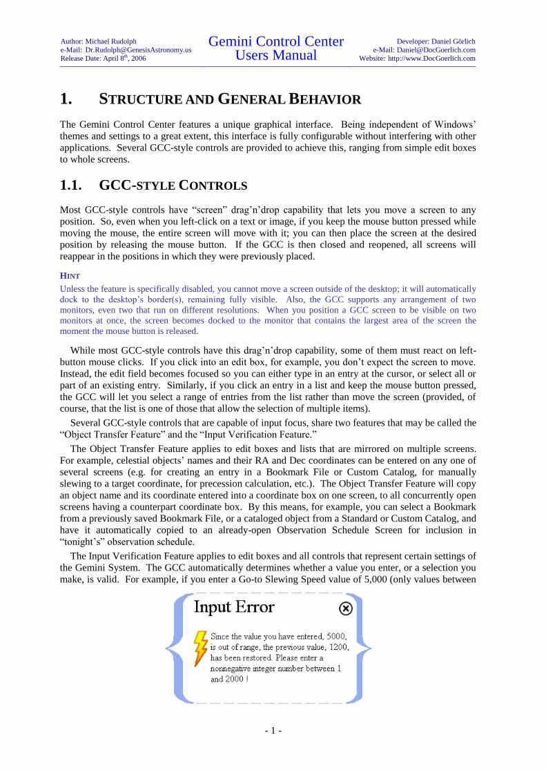
The Input Verification Feature applies to edit boxes and all controls that represent certain settings of
the Gemini System. The GCC automatically determines whether a value you enter, or a selection you
make, is valid. For example, if you enter a Go-to Slewing Speed value of 5,000 (only values between

Author: Michael Rudolph
e-Mail: [email protected]
Release Date: April 8th, 2006
Gemini Control Center Users Manual
Developer: Daniel Görlich
e-Mail: [email protected]
Website: http://www.DocGoerlich.com
- 2 -
1 and 2,000 are allowed), the GCC will reject the entry, automatically restore the previous value, and
show a warning like the one above.
Similarly, the GCC always checks to make sure that a setting value sent to the Gemini System was
correctly adapted. After a few milliseconds, it asks the Gemini for the value of this setting, and
compares it to the one just sent. If the two are not the same, the GCC logs the failure and displays
Gemini’s value (ignoring the one just sent), thus alerting the user that a problem has occurred, or that
Gemini has re-interpreted (e.g. re-formatted) the value the user had just entered.
Conversely, the GCC performs syntactical and semantic checks on values and information it
retrieves from the Gemini System; it only accepts those whose formats are correct and “make sense.”
All incorrect responses and failures are saved to log files so that, in case of repeated erroneous
communications or failures, you can (hopefully) find the problem by analyzing the three log files,
“ErrorLog.log,” “Traces.log,” and “CommLog.log;” these are stored in the same directory as the GCC
executable file, “Gemini.exe.” All important GCC events and the complete record of communication
between the GCC and the Gemini System are stored in these three log files; the log files are emptied
and overwritten each time the GCC is launched after having been closed.
Some features do not apply to a given type of control in all circumstances, but are only available in
specific contexts. The grid control, being one of the GCC’s more complex controls, is a good
example. Single-column grids usually provide lists of applicable settings, files, database entries, etc.
Multi-column grids (or tables) usually show properties of a number of items in a formatted or
interpreted manner.
In some lists, only one item can be chosen; for example, only one Mount Type can be selected at a
time. In other tables, however, you can select multiple items at once, as shown in the illustration on
the right. You cannot, however, select non-contiguous items, but only a range of items. You can
usually rearrange those items, however, using the move arrows as described below. This would be
useful, for example, in the case of the objects listed in a Custom Catalog. Selecting a range of items
on a list can be done in either of two ways: (1) select an item on the list and mouse-drag the cursor up
or down the list to highlight contiguous items; (2) select an item on the list and then Shift-click a
second item some distance from it.
The options available for a specific table are signaled by the icons embedded in the table’s frame.
To the right of the table are the up and down scroll buttons; the outer ones scroll the table to the first or
last item respectively; the middle (double-arrow) buttons scroll up or down by several items;3 the inner
(single-arrow) buttons scroll up or down, one item at a time. At the bottom of the table, up to three
buttons can be available. Those are the up or down “move” arrows and the delete mark . The
“move” arrows move the currently selected item(s) up or down, thereby allowing you to rearrange the
items in the table.
The functionality of the delete mark is context-dependent. Of course, clicking the delete mark will
delete the currently selected item(s) from the grid but, if the grid contains a list of files, clicking the
delete mark will also delete the file(s) from the Windows folder where they are stored. Another
example of context-dependence is that, if the last element of an Observation Diary is deleted, the
Observation Diary Screen will close completely. The exact ways that context-dependent functions
work for specific grids are described in detail in each of their respective chapters of this manual.
3 The number of lines scrolled with each click of the button depends upon the total number of items in the list:
10 lines if from 1 to 2000 items; 200 lines if from 2001 to 20,000 items; 2000 lines if more than 20,000 items.

Author: Michael Rudolph
e-Mail: [email protected]
Release Date: April 8th, 2006
Gemini Control Center Users Manual
Developer: Daniel Görlich
e-Mail: [email protected]
Website: http://www.DocGoerlich.com
- 3 -
1.2. SYNCHRONIZATION
The GCC always tries to keep itself synchronized with the Gemini System. When a connection
between Gemini and the GCC is first established, the GCC immediately loads all of the Gemini’s
current settings and data. After that, the GCC continues to upload any changing data, such as the
current pointing position.
You cannot change the GCC’s settings while unconnected, thinking that you will establish the
connection later. If you do, all the changes you made will be lost. However, you can preserve the new
settings by saving them into a Session Profile (using the Configuration Screen) and then, after you
have reconnected to Gemini, by loading and applying the saved Profile. All of the settings in the
saved Profile, including those you previously changed, will be downloaded to the Gemini, once more
establishing a state of synchronization.
Also, any time you change a Gemini setting using the GCC, the GCC first sends the new setting
down to the Gemini System, and then retrieves it, in order to verify that its value has been adjusted
correctly. Furthermore, it retrieves data that might have changed in the process: For example, the
GCC automatically reloads all Modeling Parameters after you have selected a new Tracking Speed.
The GCC cannot know if and when you change a setting using Gemini’s Hand Controller. The
GCC is therefore designed so that you usually do not have to make use of the Hand Controller. If you
do anyway, you can opt to use the GCC’s Hand Controller Emulation feature remotely, instead of
Gemini’s Hand Controller at the telescope; either way, you will probably have to synchronize the
GCC and the Gemini System manually using the Synchronization Screen. Special procedures required
for simultaneously using the GCC with either Gemini’s Hand Controller or the GCC’s Hand
Controller emulator are discussed in subsequent chapters of this manual.
You may occasionally want to control the Gemini System simultaneously from both the GCC and a
third-party software. To do this, a trick is needed. Since only one software application can access the
active serial port at a time (the one used for communicating with the Gemini), the GCC has to free the
port when you want the other software to take over; the same is true of that software when you want
the GCC to seize control again. This is accomplished through a setting found on the Configuration
Screen. Its use is described in detail in the chapter of this manual entirely devoted to that screen.
1.3. ADAPTABLE USER INTERFACE
Since the Gemini has now undergone three level upgrades (the most recent being Level 4), a way was
sought so that a single version of the GCC could serve all four Gemini levels without confusing the
user by inapplicable control features appearing on his computer screen. The solution decided
upon, was to program into the GCC, an Adaptable User Interface – one that automatically recognizes
the Gemini level, and displays only those controls that are needed to operate that particular level.
For example, if the GCC is connected to a Level 1 Gemini, no “Hardware” selection option will
appear on the Main Screen because the Level 1 Gemini did not support remotely setting mount
parameters, Hand Controller modes, axis encoder settings, and modeling parameters. Similarly, if the
GCC is connected to a Level 4 Gemini, the Manual Control Screen of the GCC will show an
Altitude/Azimuth display and a Hand Controller Emulation that will not be shown for the older levels.
Because this manual was written for the Level 4 Gemini user (Level 4 is the most recent of the
Geminis and therefore contains the most features), special icons are provided in the margins to alert
the user to when a described feature is not available in an earlier Gemini level. For example, the
description of a feature appearing adjacent to an L4 icon (see example on the right) means that the
feature is only available in Gemini Level 4; similarly, if the description of a feature appears adjacent to
L2, L3 and L4 icons (see second example on the right), the feature is absent in Level 1.
It is sincerely hoped that the Adaptable User Interface of the GCC and the level-specific icons in
this manual, will help the user to quickly and efficiently learn to operate the GCC with whichever
level of Gemini he or she owns.

Author: Michael Rudolph
e-Mail: [email protected]
Release Date: April 8th, 2006
Gemini Control Center Users Manual
Developer: Daniel Görlich
e-Mail: [email protected]
Website: http://www.DocGoerlich.com
- 4 -
2. THE MAIN & STATUS SCREENS
OVERVIEW
The Main Screen contains three kinds of structures – control buttons, menu icons, and function
buttons. The control buttons are for hiding the screen, making the screen’s wallpaper transparent,
minimizing and closing the GCC, and displaying credits. A special button toggles between Day and
Night Vision Mode, and the flag buttons allow you to select the language of each country whose flag
is displayed. The four function buttons at the bottom of the screen can connect or disconnect the GCC
from Gemini, park the telescope in its Startup or Home positions,4 and interrupt slewing movements in
emergencies. Finally, hovering the mouse over any of the three large icons located near the center of
the screen causes its respective menu to be displayed, and clicking on any menu item launches its
screen.
The Real-Time Status Screen is unique among the GCC screens in that it receives no inputs, and
performs no functions other than to display important status data that the telescope operator may want
to monitor continuously. It is complementary to the Main Screen in that together, they serve as the
hub of operations for controlling the Gemini from a PC.
2.1. THE MAIN SCREEN
The Main Screen is launched whenever the GCC is opened. It is the screen from which all other GCC
screens are launched, and the only screen from where the GCC can be closed. The Main Screen is
truly the “switch round-house” of all Gemini Control Center operations.
4 GCC’s Startup Position button and function is only available in Gemini Levels 3 and 4.

Author: Michael Rudolph
e-Mail: [email protected]
Release Date: April 8th, 2006
Gemini Control Center Users Manual
Developer: Daniel Görlich
e-Mail: [email protected]
Website: http://www.DocGoerlich.com
- 5 -
2.1.1. THE CONTROL BUTTONS
In the top right corner of the Main Screen, you’ll find several small round
buttons encircling a larger Moon button. The number of small buttons is
either five or six, depending upon considerations described below. From
left to right, they are:
1. The Zoom button. Clicking it toggles between the default screen
resolution, and 1024 768. If 1024 768 is already the screen
resolution when the GCC starts up, this button will not be visible at
all.
2. The Transparency Mode button. Clicking it (or typing Ctrl-T) toggles the visibility of the
GCC’s background wallpaper. When the wallpaper is hidden, you can see Windows’ desktop
or other applications that have been hiding behind the GCC’s screens.
HINT
Since the color themes apply to the GCC’s screens only, other applications won’t adapt them. In Night
Vision Mode, you should therefore hide the desktop and other applications, which might be much
brighter than the GCC’s screens.
3. A Minimize button is next. Clicking this button minimizes the GCC and all its open screens to
the taskbar, consolidating them all into an icon named “GCC.” Clicking this icon restores the
Main Screen and all the screens that were previously visible.5
HINT
The “GCC” icon in the taskbar continuously displays the telescope’s
RA and Dec pointing position, provided the “Trace position when
inactive” feature is enabled in the Configuration Screen.
4. Adjacent to the Minimize button is a Hide button.
Clicking it hides the Main Screen from view and launches
a small Pop-up from which the Main Screen can be
restored by clicking “Open Main Screen” (An alternative
way of hiding and restoring the Main Screen is to type
Ctrl-M repeatedly).
HINT
A Hide button has been placed on all other GCC screens as well, but the Status Screen is the only one
other than the Main Screen that can be restored via the Pop-up. In addition to having an “Open Main
Screen” and “Open Status Screen” button, the Pop-up has a Minimize button that behaves identically to
the Minimize button on the Main Screen.
5. The Close button closes the GCC application, thereby breaking its connection to the Gemini
System.
6. The Copyright button opens the Gemini Credits Screen, which provides the e-mail address of
the GCC’s developer, and links to his website, and to the Gemini Users’ support newsgroup.
By clicking the central Moon button, you can toggle between Daylight and Night Vision Mode.
This occurs even if you have previously loaded a Custom Color Theme.6 The screenshot on the next
page shows the GCC’s Main Screen in Night Vision Mode.
5 See the “Trace position when inactive” feature in the “Connection Parameters” section of the “Configuration
Screen” chapter. 6 For more information on how to create and load Custom Color Themes, refer to chapter 13: “The Themes
Screen.”

Author: Michael Rudolph
e-Mail: [email protected]
Release Date: April 8th, 2006
Gemini Control Center Users Manual
Developer: Daniel Görlich
e-Mail: [email protected]
Website: http://www.DocGoerlich.com
- 6 -
Below the Moon button are several countries’ flags. By clicking on one of them, you apply the
language of the country that owns the flag. If you click the British flag, for example, all the GCC’s
screens, messages, texts and so on, are presented in English; if you click the German flag, everything
is presented in German.
2.1.2. THE MENU ICONS AND THEIR SCREENS
There are three Menu Icons that surround
a central box titled “Screen Selection.”
Allowing your mouse to hover over any
of the icons causes the menu of that icon
to be displayed in the box; each of the
menus is a list of the screens that can be
launched by merely clicking them.
Hovering the mouse over the Observa-
tion Menu Icon, displays the menu items:
Catalogs
Near Objects
Schedules
Logs & Diaries

Author: Michael Rudolph
e-Mail: [email protected]
Release Date: April 8th, 2006
Gemini Control Center Users Manual
Developer: Daniel Görlich
e-Mail: [email protected]
Website: http://www.DocGoerlich.com
- 7 -
Hovering the mouse over the Telescope
Menu Icon, displays the menu items:
Hardware
Manual Control
Telescope Site
Synchronization
Hovering the mouse over the Tools
Menu Icon, displays the menu items:
Status
Precession
Configuration
Color Themes
Information on the content of the
screens and their use can be found in the
sections of this manual named after, and
devoted to, each screen.
2.1.3. THE FUNCTION BUTTONS
There are four function buttons at the bottom of Main Screen.7 The “Connect/Disconnect” button is a
duplicate of the same button that is in the Manual Control Screen. Clicking the button while its label
reads “Connect,” causes the GCC to search for an available serial port on the PC, thereby connecting
the PC to the Gemini. Once connected, the button’s label changes to read “Disconnect;” clicking the
button while it is in that condition, causes the PC and the Gemini to become unconnected once again.
For a more detailed explanation of the Connect/Disconnect function, see “Connecting, Disconnecting
and Rebooting Gemini” in the Manual Control Screen chapter.
HINT
If Gemini is powered off while the GCC is connected to it, the GCC will continue to appear connected and its
Status Screen will continue to display “Online.” To avoid being misled by the display, it is best to disconnect
the GCC before turning off Gemini.
The “Startup Position,” “Home Position,” and “Emergency Stop” buttons are also duplicates of
buttons that are in the Manual Control Screen; they appear here as well for the users’ convenience.
The “Startup Position” button parks the telescope in its original “Startup Position,” the “Home
Position” button parks the telescope in a pre-determined “Home Position,”8 and the “Emergency Stop”
button abruptly stops all slewing movement, even in the middle of a slew; an alternative way to stop
all movement is to type Ctrl-S. For more information about these three buttons’ functions, consult the
Manual Control Screen chapter of this manual.
7 Only Levels 3 and 4 utilize a Startup Position button.
8 A “Home” position may be set via Gemini’s Hand Controller but not in the GCC. If a “Home” position is not
set, the Home Position button defaults to the Startup position.

Author: Michael Rudolph
e-Mail: [email protected]
Release Date: April 8th, 2006
Gemini Control Center Users Manual
Developer: Daniel Görlich
e-Mail: [email protected]
Website: http://www.DocGoerlich.com
- 8 -
HINT
Emergency stopping does not stop the telescope from tracking. That must be done from the Hardware Screen by
setting the Tracking Speed to None/Terrestrial.
2.2. THE REAL-TIME STATUS SCREEN
The Real-Time Status Screen is opened whenever the GCC is launched because, together with the
Main Screen, it is part of the GCC’s default configuration. It can be hidden from view by clicking its
Hide button, and can be reopened by clicking the “Status” item of the Main Screen’s “Tools” menu, or
by clicking the “Open Status Screen” button in the Pop-up that results from hiding the Main Screen.
The name of this screen accurately describes its purpose, which is to consolidate in one place, the
most commonly needed real-time data that the user may want to continuously monitor, as he or she
attends to the various tasks of astronomical observing.
2.2.1. TIME DISPLAYS
When the GCC is not connected to the Gemini, only the PC’s civil, UTC, and sidereal times are
displayed. On most PCs, the clock is set by entering the local civil time and the time zone into
Windows; the UTC and sidereal times are derived from them.
Upon connecting to the Gemini, all the other values in the Real-Time Status Screen are displayed as
soon as they become available. Completing the left-hand column of the screen is the “Gemini Local
Time” display which, ideally, should be identical to the PC’s “Computer Civil Time.” If it is not,
Gemini’s time can be synchronized, via either the Synchronization or Telescope Site Screens, to a
GPS receiver or to the PC’s internal clock. As an additional convenience, the PC’s clock can be
synchronized, using these same two screens, to either a GPS receiver or to an atomic clock via the
Internet.
2.2.2. POSITION, HOUR ANGLE, MOUNT SIDE, AND MOTION
The center column of the Real-Time Status Screen displays the Hour Angle, the telescope’s position
coordinates in Right Ascension (RA) and Declination (Dec), the side of the mount (East or West) to
which the telescope is leaning, and the status of the telescope’s motion. It also displays “(logging)”
while a Position Log is being recorded and momentarily flashes “(logging)” each time the Position
Log is marked (see section 7.4 of this manual).
HINT
“Hour Angle” and “Mount Side” displays are available only for Level 4 and higher.
Monitoring the Hour Angle and the telescope’s RA and Dec position is important because they
provide confirmation that something has not gone grossly wrong with Gemini’s Go-to or tracking
functions. The RA and Dec values displayed do not change while the mount is tracking in sidereal
mode because the telescope, although it is moving relative to the Earth, continues to point to the same

Author: Michael Rudolph
e-Mail: [email protected]
Release Date: April 8th, 2006
Gemini Control Center Users Manual
Developer: Daniel Görlich
e-Mail: [email protected]
Website: http://www.DocGoerlich.com
- 9 -
place on the celestial sphere. The RA and Dec values do change, however, when the telescope is
parked or set to terrestrial tracking. This is because, although the telescope is stationary relative to the
Earth, the coordinates to which it points keep changing as the celestial sphere seems to pass overhead.
The Real-Time Status Screen is not the only place in the GCC that displays the telescope’s RA and
Dec position coordinates; the Manual Control Screen displays them as well, as does the Bookmarks
Panel on the Catalogs Screen when in Position Display Mode.
“Mount Side” displays either “East” or “West,” depending upon the side of the mount to which the
telescope is leaning in Right Ascension. For example, when you are standing behind the telescope
mount facing north, an “East” display means that the telescope is leaning to your right, while “West”
means it is leaning to your left. Since German Equatorial Mounts can often target the same celestial
object by leaning to either side, this display is useful for keeping track of the telescope’s RA position
when its location is such that the telescope cannot be seen by the user.
The Motion indicator alerts you to the nature of the telescope’s current movement (centering,
guiding, slewing, tracking, or motionless); it can be conveniently monitored from the Manual Control
Screen as well. This feature serves as a reminder of the telescope’s tracking motion, and a check on
whether the Gemini is responding properly to a movement command.
2.2.3. GEMINI’S SYSTEM STATUS
The right column of the Real-Time Status Screen contains five important items related to Gemini’s
system status. The first item, “Connection,” displays the current status of Gemini’s connection to the
GCC. “Offline” is displayed if the two are not connected, “Online” if they are connected, and
“Scanning” while the GCC is scanning the PC’s serial ports in search of a Gemini device. Connecting
and disconnecting are initiated from either the Main Screen or the Manual Control Screen.
HINT
If Gemini is powered off while the GCC is connected to it, the GCC will continue to appear connected and its
Status Screen will continue to display “Online.” To avoid being misled by the display, it is best to disconnect
the GCC before turning off Gemini.
The next item in the right column, “Level,” displays the upgrade level of the Gemini that is
connected to the GCC.
The “Limit Reached” indicator signals the user when the telescope has stopped moving in RA
because a previously-set limit has been reached. RA Safety Limits protect the telescope and the
mount from colliding with each other during tracking and slewing movements; they are set in the
Hardware Screen.
The “Initial Alignment” indicator on the Real-Time Status Screen tells the user whether or not the
telescope has been initially aligned. Gemini Levels 3 and 4 are initially aligned (at least
approximately) the moment Gemini is powered on and started. The accuracy of this automatic initial
alignment depends upon how accurately the mount was polar aligned, and how accurately the
telescope was placed in the standard Startup position prior to being powered on. Gemini Levels 1 and
2 are not aligned when first powered on, and must be initially aligned manually. When a Level 1 or 2
Gemini is started up and the GCC notices that no initial alignment has been done, it launches an Initial
Alignment Screen from where you can select and download a suitable cataloged object on which to
initially align the telescope.
HINT
The Initial Alignment Screen (only available for Levels 1 and 2) can be manually closed by the user, but can
only be opened by the GCC automatically.
The last item in the Real-Time Status Screen is “Modeling.” Modeling “Yes” means that Gemini
has built up and is using a pointing model generated via Gemini’s Synchronize and Additional Align
commands. Modeling “No” alerts the user that a pointing model has not been generated, that a
previous model has been lost, or that Gemini has been told not to use the model.

Author: Michael Rudolph
e-Mail: [email protected]
Release Date: April 8th, 2006
Gemini Control Center Users Manual
Developer: Daniel Görlich
e-Mail: [email protected]
Website: http://www.DocGoerlich.com
- 10 -
HINT
Gemini might reset its pointing model when, for example, the Mount Type has been switched. After that, one or
two Additional Alignments are sufficient to build a new model, which Gemini will start using instantly if it
hasn't been told otherwise. When Gemini loses its pointing model, a warning pops up that states: "Gemini is no
longer aligned; please align the telescope manually, and Cold Start Gemini. Alternatively, manually slew Gemini
to an arbitrary object, center it in the telescope, and Synchronize!"
ANOTHER HINT
Even if a pointing model has been generated, the GCC can instruct Gemini not to use it. For a description of this
feature, see the first Gemini Option in section 2.2.4 (The Advanced Options Panel) below.
2.2.4. THE ADVANCED OPTIONS PANEL
An Advanced Options Panel can be deployed by typing Ctrl-O on the PC’s keyboard; there is no
button in the GCC that can deploy this panel. The Advanced Options Panel contains settings and
functions that are highly specialized or not often used, and are gathered here so as not to clutter other
screens.
The first GCC Option allows you to readjust the GCC to specified Gemini levels (1.1, 1.2, 2, 3, or
4). When the GCC connects to a Gemini, it detects the Gemini’s level and configures itself
accordingly. This option allows you to reconfigure the GCC for other Gemini levels so that you can
see and compare their capabilities. Of course, you must not expect that a higher GCC configuration
level will function properly with a lower level of Gemini, so it is strongly advised that users upgrade
to the highest Gemini level that they can acquire.
HINT
Readjusting the GCC to a Gemini Level that is not currently in use causes the GCC to disconnect. The GCC
automatically reverts to the currently used level as soon as the connection is reestablished.

Author: Michael Rudolph
e-Mail: [email protected]
Release Date: April 8th, 2006
Gemini Control Center Users Manual
Developer: Daniel Görlich
e-Mail: [email protected]
Website: http://www.DocGoerlich.com
- 11 -
The second GCC Option allows you to display the GCC’s Communications and Error Logs on its
wallpaper. These are dynamic displays that can be useful for development and real-time trouble-
shooting.
The third GCC Option allows you to dock or undock the GCC’s screens to the PC monitor’s
borders. In most cases, the screens should remain docked. However, undocking allows you to
position a screen partially off the desktop when you want to display multiple open screens with little
or no overlap.
The fourth GCC Option utilizes a button labeled “Hide all but Main & Status Screens” that does
exactly that! This function is useful for efficiently closing all open screens except for the Main and
Status Screens with one click of the button.
The fifth and last GCC Option included on the Advanced Options Panel utilizes a button labeled
“Rearrange Main & Status Screens.” This is used to automatically return the Main and Status Screens
to their initial positions with the Main Screen centered over the Status Screen, and both of them
centered on the primary desktop.
All Gemini Options require Gemini Level 4. The first one allows you to check a box, thereby
causing the Gemini to disregard (but not delete) any Pointing Model that may have been developed as
a result of your having done multiple star alignments. Unchecking the box immediately causes the
Gemini to resume using its prior Pointing Model.
The second Gemini Option is executed with the press of the button labeled “Perform Meridian
Flip.” German Equatorial Mounts are unique in that a certain array of celestial coordinates can be
pointed to with the telescope leaning to either the East or West side of the mount. In such cases,
clicking the “Perform Meridian Flip” button causes the telescope to first note the RA and Dec
coordinates to which the telescope is pointing, then to swing the telescope in RA to the opposite side
of the mount (passing through the meridian), and finally to resume pointing toward the same
coordinate pair as before.
HINT
If the telescope is initially leaning to the East, performing a Meridian Flip results in it leaning to the West (and
visa versa). Then, performing a second Meridian flip returns the telescope to its original position.
The third Gemini Option utilizes a button that, when clicked, sets the Gemini to Mountain
Instruments’ default parameters that includes selecting the MI250 mount, and setting Mountain
Instruments’ default safety limits, slewing speed, encoder resolutions, and home geographic location.
HINT
To reset Gemini to Losmandy’s default parameters, click “Reset Defaults” in the Manual Control Screen (see
section 9.1.4 of this manual). Because all of Losmandy’s default settings may not be what you desire, a prudent
second step might be to retrieve and apply a previously saved Session Profile.
The fourth and final Gemini Option included on the Advanced Options Panel, are basic (but not all)
of the PEC (Periodic Error Correction) commands and messages of which Gemini Level 4 is capable.
The commands included on the panel are “Turn On,” “Turn Off,” and “Clear Data.” The two
categories of messages that are displayed are “PEC Status,” and “PEC Training.” The possible PEC
Status messages that can be displayed are (1) “Active, data available,” (2) “Inactive, data available,”
and (3) “Inactive, data not available.” The possible PEC Training messages that can be displayed are
(1) “Freshly trained,” (2) “In progress,” (3) “Just completed,” and (4) “Will start soon.”
The PEC functions not included on the Advanced Options Panel can be performed via Gemini’s
Hand Controller, or the GCC’s Hand Controller Emulation.
HINT
The PEC controls on the GCC’s Advanced Options Panel only function when Gemini PEC data is available.

Author: Michael Rudolph
e-Mail: [email protected]
Release Date: April 8th, 2006
Gemini Control Center Users Manual
Developer: Daniel Görlich
e-Mail: [email protected]
Website: http://www.DocGoerlich.com
- 12 -
3. THE CONFIGURATION SCREEN
OVERVIEW
The Configuration Screen is launched from the Tools menu on GCC’s Main Screen by clicking
“Configuration.”
This screen performs two basic functions; it (1) provides a place for setting the GCC’s connection
parameters, and (2) it allows you to construct, save, retrieve, edit, and delete Session Profiles.
Session Profiles are templates of all parameters to which the Gemini can be set. The GCC’s ability
to define, store and retrieve profiles is an immense timesaver because it enables the observer to pre-
plan Gemini’s settings for different kinds of observations, made at different geographic locations.
3.1. RS232 INTERFACE
If your PC provides a serial RS232 port, you should use this port to connect your PC to your Gemini
System. You can either purchase a cable from Losmandy – look up the “Gemini > Computer Cable” at
http://www.losmandy.com/pricelist.html – or build one yourself. For this, please refer to the Gemini’s
Users Manual, chapter 6.1!
If your PC does not provide a native RS232 port anymore, you will have to interpose, for example,
a USB-to-RS232 adapter that creates virtual serial COM ports.

Author: Michael Rudolph
e-Mail: [email protected]
Release Date: April 8th, 2006
Gemini Control Center Users Manual
Developer: Daniel Görlich
e-Mail: [email protected]
Website: http://www.DocGoerlich.com
- 13 -
3.2. CONNECTION PARAMETERS
There are six connection parameters that can be set from this screen by placing checks in appropriate
checkboxes.
When checked, “Scan ports at program start” causes the GCC to search the PC for an available
serial port through which to connect with the Gemini. COM1 through COM12 are scanned, and the
GCC connects to the first port that is not occupied, and on which a Gemini System is found. Leaving
the box unchecked disables the GCC’s automatic port scan at startup.
When checked, “Start GCC in transparency mode” causes the GCC to launch without its opaque
background. This setting enables you to always see the open windows of other applications, and the
icons on your Windows desktop.
When checked, “Save settings at program termination” saves all GCC settings to a configuration
file so that, when the program is restarted, the parameters previously defined do not have to be
reentered.9 This is time-saving when multiple observation sessions use the same or nearly the same
parameters. Also, when the GCC is started up the next time, all those saved settings are restored so
that, for example, all the screens that were previously visible automatically open at the same position
as before.
Leaving the box unchecked results in a loss of currently saved settings because no new
configuration file is created. Consequently, on starting up again, the settings revert to those previously
saved or to the default configuration (i.e. as long as the box is unchecked, the GCC keeps starting up
in the same configuration).
HINT
The created or updated configuration is stored in GCC’s “Databases” subdirectory in a plain text file named
“GCC_Config.ini.” Using Windows tools, you can save or back up this file with a different name at any time,
and you can overwrite the current configuration file with a previously saved one in order to restore a desired
configuration. Finally, you can reset the complete configuration by deleting the “GCC_Config.ini” file; this
makes the GCC load the built-in default configuration the next time it starts.
When “Save current configuration to recycle bin” is checked, each time a new configuration file
(“GCC_Config.ini”) is saved to the hard disk, the old one is stored in Windows’ recycle bin. This
setting is useful when you do not want to lose the previous configuration, but rather temporarily store
it for later retrieval.
HINT
To restore a previous configuration, retrieve the configuration file from the recycle bin and paste it into GCC’s
“Databases” folder in place of the same-named file already there. Also, “GCC_Config.ini” can be deleted from
the “Databases” folder entirely, thereby restoring all initial settings.
When checked, “Close port at deactivation” makes the PC’s port that was previously used by the
GCC, available for other purposes.10
This allows several applications to control the Gemini almost
synchronously (e.g. a planetarium program) because it forces the GCC to disconnect from Gemini as
soon as you switch control to the other application. This is especially useful when the GCC and a
planetarium program are both made visible by invoking the “transparency mode” from the Main
Screen. It is also useful when you want to control the Gemini and one or more other serial devices
from a PC that has a limited number of COM ports. To do this, you simply activate one control
application at a time.
9 When the GCC is started for the first time, before it is connected to any Gemini, it launches in the Daylight
Vision Mode, in the L4 (full-featured) configuration, and with only the Main and Real-Time Status Screens
displayed. This is the default appearance that results when no configuration file is found.
10 The GCC is deactivated by either minimizing it (i.e. clicking the button located on the upper right side of
the Main Screen) or by focusing another application that is running simultaneously.

Author: Michael Rudolph
e-Mail: [email protected]
Release Date: April 8th, 2006
Gemini Control Center Users Manual
Developer: Daniel Görlich
e-Mail: [email protected]
Website: http://www.DocGoerlich.com
- 14 -
When “Trace position when inactive” is checked, the GCC continuously updates its knowledge of
the telescope’s pointing position even when another application is focused (provided the other
application is not itself connected to Gemini and taking up the port). This is accomplished by the
GCC attempting to make a brief (several millisecond) connection to the Gemini every second, even
when it is inactive; during any period when the GCC cannot make the connection, the telescope’s
position will, of course, not be updated.
HINT
This feature should not be activated if it prevents other applications from connecting to the Gemini while Gemini
is updating its data. If the feature is not activated, the GCC will, nevertheless update itself as soon as its
connection with Gemini is restored.
3.3. SESSION PROFILES
As previously explained, Session Profiles are templates of all (or a selection of all) parameters to
which the Gemini can be set. Since there are differences in the various levels of Gemini as to which
parameters can be set, the composition of the Session Profiles is also level-dependent.
3.3.1. CREATING PROFILES
To create a profile, enter the settings (parameters) you desire in the appropriate GCC screens. If you
want your profile to include modeling parameters, you must also perform the requisite alignments and
synchronizations described in the Gemini Users Manual. When that is done and you click “Collect
Current Settings,” all of the parameter settings appropriate to your level of Gemini will appear in the
list at the lower right of the Configuration Screen.
You can now save all of the collected parameters as a profile or you can delete some of them before
saving. To select a single parameter for deletion, click on it in the list. To select a range of parameters
for deletion, click on the first in the range, and Shift-Click on the last. The selected parameter or
parameters can now be deleted by clicking the delete mark .
3.3.2. SAVING AND DELETING PROFILES
When the parameter list is as you want it, enter a name for the profile in the “Name” box and click
“Save Profile.” The saved Session Profile will appear in the list of “Available Profiles.”
To select a single profile for deletion, click on it in the list. To select a range of profiles for
deletion, click on the first in the range, and Shift-Click on the last. The selected profile or profiles can
now be deleted by clicking the delete mark .
3.3.3. RETRIEVING AND APPLYING SAVED PROFILES
To retrieve a previously saved profile, select it from the list of “Available Profiles” and click “Load
Profile.” The settings (parameters) of the profile and their respective values will appear in the list at
the lower right corner of the screen.
If desired, one or a range of the retrieved parameters can now be deleted from the loaded profile.
To select a single parameter for deletion, click on it in the list. To select a range of parameters for
deletion, click on the first in the range, and Shift-Click on the last. The selected parameter or
parameters can now be deleted by clicking the delete mark .
Once you are satisfied with the retrieved profile’s settings, you can copy them to the appropriate
screens of the GCC by clicking “Apply Listed Settings.” If a Gemini is connected at this time, the
changes will immediately be downloaded to it as well. If a Gemini is not connected at this time but is

Author: Michael Rudolph
e-Mail: [email protected]
Release Date: April 8th, 2006
Gemini Control Center Users Manual
Developer: Daniel Görlich
e-Mail: [email protected]
Website: http://www.DocGoerlich.com
- 15 -
connected later, the Synchronization Screen can be used to “Download to Gemini” in a subsequent
step.
For example, here are steps for saving Gemini’s current modeling parameters in a profile:
1. Enter a profile name, e.g. “Current Modeling Parameters,” in the “Name” box in the
Configuration Screen.
2. Click the button labeled “Collect Current Settings.” Notice that all of Gemini’s current
settings are displayed in the parameter list in the lower right corner of the screen.
3. Select all the settings in the list that are not modeling parameters, and delete them by
clicking the delete mark . (This may require selecting and deleting several ranges of
settings.) Alternatively, you can rearrange the settings first until all the modeling parameters
are at either end of the list, and then the non-modeling parameters can be selected and
deleted as one range. The way that this is best accomplished is to (1) select the modeling
parameters as a single range (using Shift-Click), and move the entire range to the top of the
list using the “up” arrow; (2) select all of the other settings as a single range, and delete the
range. The settings that remain in the list will only be modeling parameters.
4. Now click the button labeled “Save Profile.” A profile containing only the modeling
parameters in the list has now been saved under the name “Current Modeling Parameters.”
To later restore the parameters stored in the “Current Modeling Parameters” profile, do the
following:
5. Select “Current Modeling Parameters” from the “Available Profiles” list and click “Load
Profile.” Notice that the modeling parameters that were previously saved appear as a list in
the lower right of the screen.
6. Click “Apply Listed Settings.” The GCC’s Hardware Screen now displays the modeling
parameters that were saved and retrieved and, if the GCC is connected to the Gemini, the
parameters will automatically be downloaded to the Gemini.
7. If, however, the GCC is not connected to the Gemini, an additional step will be required to
populate Gemini with the retrieved modeling parameters. When the connection is made, go
to the Synchronization Screen and click “Download to Gemini.” The Gemini will now
contain the same modeling parameters as the GCC.
Author: Michael Rudolph
e-Mail: [email protected]
Release Date: April 8th, 2006
Gemini Control Center Users Manual
Developer: Daniel Görlich
e-Mail: [email protected]
Website: http://www.DocGoerlich.com
- 16 -
4. THE CATALOGS SCREEN
OVERVIEW
The Catalogs Screen is launched from the Observation menu on GCC’s Main Screen by clicking
“Catalogs.”
This is one of the most useful screens of the GCC because (1) it is a repository of “Standard” deep
space objects, (2) it is a screen from which object coordinates (including those input by the user) can
be transferred to other screens, and (3) it is a location from where current coordinates can be
bookmarked, and user-input coordinates can be stored. In addition, it is a screen from which one can
slew to any stored celestial object by first selecting it, and then clicking the “Go-to” button that is
located at the bottom of the screen.11
Also at the bottom of the Catalogs Screen are “Additional Align” and “Synchronize” buttons. They
are placed there to assist the user in synchronizing targeted objects to the telescope's position, and for
adding objects to Gemini's pointing model if desired. The Gemini Astronomical Positioning System
Users Manual should be consulted for instructions on how to perform these functions.12
The Catalogs Screen contains three panels that are accessed by clicking their respective tabs; they
are the
Standard Catalogs Panel
Custom Catalogs Panel
Bookmarks Panel
4.1. TRANSFERRING OBJECTS BETWEEN PANELS AND SCREENS
The panels of the Catalogs Screen are among those that are “object-transferable.” Object-transferable
panels and screens are capable of automatically transferring and/or receiving named objects and their
coordinates to and from other panels and previously-opened screens. While the Custom Catalogs and
Bookmarks Panels are fully object-transferable, the Standard Catalogs Panel can only transfer out; it
cannot receive.
The transferring of an object occurs automatically whenever one is selected from an Object List or
typed into an Object Coordinate Box. So, for example, selecting Dubhe from the Bright Star Catalog
transfers Dubhe a UMa; 11h 03m 43s; +61º 45' 03" to the Object Coordinate Boxes of the other two
panels, as well as to any other object-transferable screens that are open.
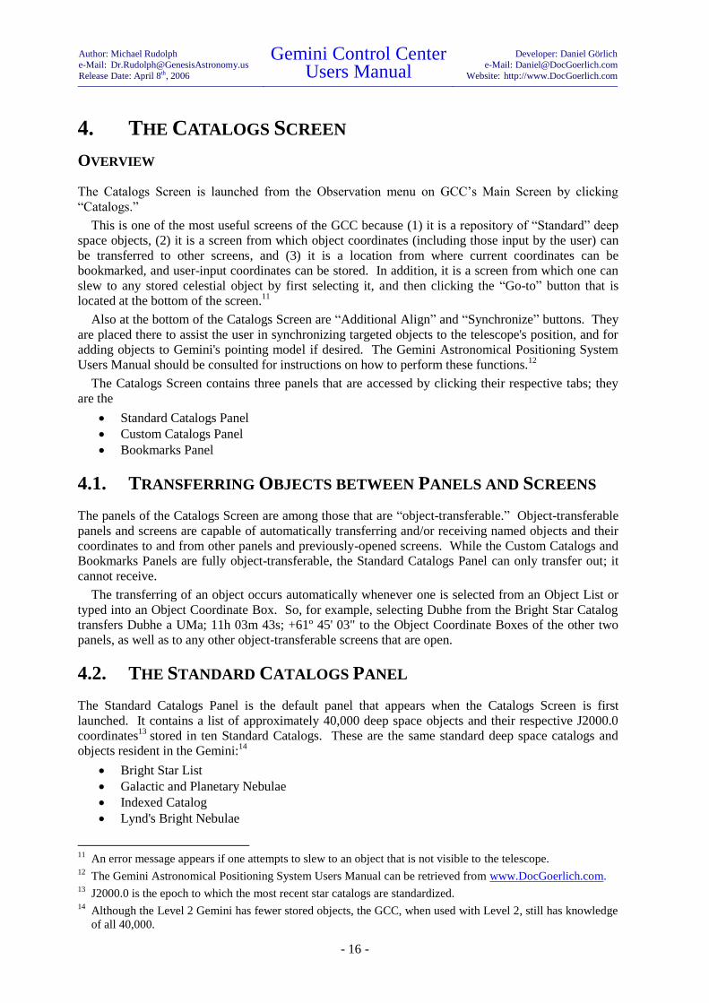
4.2. THE STANDARD CATALOGS PANEL
The Standard Catalogs Panel is the default panel that appears when the Catalogs Screen is first
launched. It contains a list of approximately 40,000 deep space objects and their respective J2000.0
coordinates13
stored in ten Standard Catalogs. These are the same standard deep space catalogs and
objects resident in the Gemini:14
Bright Star List
Galactic and Planetary Nebulae
Indexed Catalog
Lynd's Bright Nebulae
11
An error message appears if one attempts to slew to an object that is not visible to the telescope.
12 The Gemini Astronomical Positioning System Users Manual can be retrieved from www.DocGoerlich.com.
13 J2000.0 is the epoch to which the most recent star catalogs are standardized.
14 Although the Level 2 Gemini has fewer stored objects, the GCC, when used with Level 2, still has knowledge
of all 40,000.

Author: Michael Rudolph
e-Mail: [email protected]
Release Date: April 8th, 2006
Gemini Control Center Users Manual
Developer: Daniel Görlich
e-Mail: [email protected]
Website: http://www.DocGoerlich.com
- 17 -
Lynd's Dark Nebulae
Messier Catalog
New General Catalog
SAO Catalog
Sharpless Catalog of HII regions
Washington Double Star Catalog
To the left of each Standard Catalog is a checkbox. If the checkbox is checked, its corresponding
catalog is loaded, and all of its objects are displayed in the Object List below it. If the number of
displayed objects from all the catalogs combined is inconveniently large, you can uncheck one or more
of the catalogs, thereby causing them to unload.
HINT
Standard Catalog files are saved in the “Databases” folder with “.guc” extensions. Standard Catalogs can be
added and deleted there, and can be overwritten by updated catalog files. If any Standard Catalog fails to display
for selection, the respective file may either be misnamed, or missing entirely.
4.2.1. RETRIEVING AND SLEWING TO STANDARD CATALOG OBJECTS
As stated previously, to display the objects contained in a Standard Catalog, you enter a check in the
adjacent checkbox; the contents of each checked catalog then becomes visible in the Object List
below. To slew to a cataloged item, simply select it from the Object List and click “Go-to.”
Since the objects contained in Standard Catalogs cannot be deleted, if only certain of the objects are
needed for a night’s observation, you may transfer them, along with their respective coordinates, to a
Custom Catalog, Bookmark File, or Observation Schedule established for that purpose (see the
Author: Michael Rudolph
e-Mail: [email protected]
Release Date: April 8th, 2006
Gemini Control Center Users Manual
Developer: Daniel Görlich
e-Mail: [email protected]
Website: http://www.DocGoerlich.com
- 18 -
procedure for transfer described in the section of this chapter entitled “Transferring Objects between
Panels and Screens”).
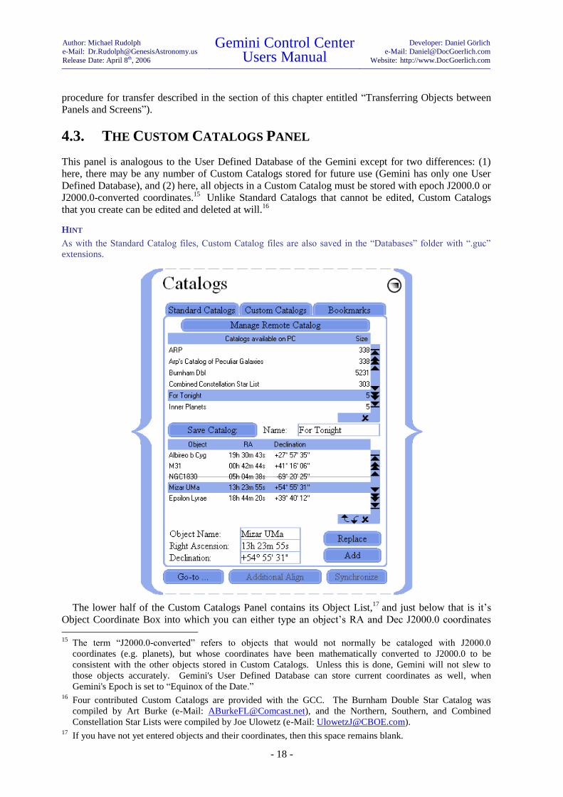
4.3. THE CUSTOM CATALOGS PANEL
This panel is analogous to the User Defined Database of the Gemini except for two differences: (1)
here, there may be any number of Custom Catalogs stored for future use (Gemini has only one User
Defined Database), and (2) here, all objects in a Custom Catalog must be stored with epoch J2000.0 or
J2000.0-converted coordinates.15
Unlike Standard Catalogs that cannot be edited, Custom Catalogs
that you create can be edited and deleted at will.16
HINT
As with the Standard Catalog files, Custom Catalog files are also saved in the “Databases” folder with “.guc”
extensions.
The lower half of the Custom Catalogs Panel contains its Object List,17
and just below that is it’s
Object Coordinate Box into which you can either type an object’s RA and Dec J2000.0 coordinates
15
The term “J2000.0-converted” refers to objects that would not normally be cataloged with J2000.0
coordinates (e.g. planets), but whose coordinates have been mathematically converted to J2000.0 to be
consistent with the other objects stored in Custom Catalogs. Unless this is done, Gemini will not slew to
those objects accurately. Gemini's User Defined Database can store current coordinates as well, when
Gemini's Epoch is set to “Equinox of the Date.” 16
Four contributed Custom Catalogs are provided with the GCC. The Burnham Double Star Catalog was
compiled by Art Burke (e-Mail: [email protected]), and the Northern, Southern, and Combined
Constellation Star Lists were compiled by Joe Ulowetz (e-Mail: [email protected]). 17
If you have not yet entered objects and their coordinates, then this space remains blank.

Author: Michael Rudolph
e-Mail: [email protected]
Release Date: April 8th, 2006
Gemini Control Center Users Manual
Developer: Daniel Görlich
e-Mail: [email protected]
Website: http://www.DocGoerlich.com
- 19 -
manually, or transfer them from elsewhere in the GCC; you must click “Add” for the object and its
coordinates to appear in the Object List.
The upper half of the Custom Catalogs Panel is its Catalog List containing the catalogs you have
created.18
Just below the Catalog List are a Catalog Name Box and a “Save Catalog” button. The
functions of these are clear – to save as a named Custom Catalog, the items appearing in the Object
List beneath it.
HINT
Changes to the content of a Custom Catalog are not automatically saved when loading another Custom Catalog
or when quitting the GCC. To save these changes you must click “Save Catalog.”
4.3.1. RETRIEVING AND SLEWING TO CUSTOM CATALOG ITEMS
Custom Catalogs that have previously been saved, automatically appear in the Custom Catalog List
when the Custom Catalogs Panel is open. To display the items contained in a Custom Catalog, select
it; its contents will then immediately be visible in the Object List.
To slew to a cataloged item, simply select it from the Object List and click “Go-to.”
4.3.2. STORING NEAR OBJECTS IN A CUSTOM CATALOG
On occasion, an observer may want to include a near (e.g. solar system) object in a custom catalog for
the purpose of observing it at a future date and time. This can best be accomplished as follows: (1)
Open the Catalogs Screen and display the Custom Catalogs Panel; (2) Open the Near Objects Screen;
(3) Select the near object of interest; (4) enter the expected date and time of observation in the Base
Date Box and the Base Time Box; (5) Click “Copy Coordinates;” (6) Note that the object of interest
with its J2000.0-converted coordinates has been accurately transferred to the Object Coordinate Box
of the Custom Catalogs Panel; (7) Click “Add.”
The selected near object will appear in the Object List as a J2000.0-converted entry. After you are
finished adding other desired objects, save the list as a Custom Catalog by naming it and clicking on
“Save Catalog.”
HINT
Since the saved Custom Catalog contains an object whose coordinates are date/time-specific, it is advisable to
include the target date and time in the Custom Catalog’s name for reference. Bookmark Files and Observation
Schedules are better vehicles than Custom Catalogs, for saving more than one near object for a future observing
session.
A more lengthy method for storing near objects in a Custom Catalog involves the use of a
planetarium program in combination with the GCC's Precession Calculator Screen. The planetarium
program can predict the actual positions of objects at designated dates and times, and the Precession
Calculator Screen can convert them to J2000.0. The near object with its converted coordinates can
then be added to the Object List of the Custom Catalog Screen, and saved into a Custom Catalog.
4.3.3. MANAGING GEMINI’S USER DEFINED CATALOG REMOTELY
In most cases, you will be using the Standard Catalogs, Custom Catalogs, and Bookmarks that are
stored on your PC. There are, however, occasions when your PC (and therefore your GCC) will not
be available for an observing session (e.g. when you are traveling lightly), and you therefore want to
store certain objects in Gemini’s User Defined Catalog for later access via Gemini’s Hand Controller.
To manage Gemini’s User Defined Catalog from the GCC, please follow the directions given below:
18
If none have yet been created, then this space remains blank.

Author: Michael Rudolph
e-Mail: [email protected]
Release Date: April 8th, 2006
Gemini Control Center Users Manual
Developer: Daniel Görlich
e-Mail: [email protected]
Website: http://www.DocGoerlich.com
- 20 -
Display the Custom Catalogs Panel and click “Manage Remote Catalog.” A previously hidden
panel will appear to the right labeled “Remote Catalog” and, beginning with Level 4, the number of
objects currently stored in Gemini’s User Defined Catalog will be displayed. From this point on,
management of Gemini’s User Defined Catalog (herein also called the “Remote Catalog”) involves
moving objects back and forth between Gemini and the Object List of the GCC’s Custom Catalog
Panel.
To upload objects from the Remote Catalog to the GCC, click “Upload Gemini’s Catalog” in the
Remote Catalogs Panel.19
Two checkboxes affect how this upload occurs:
The first of these is labeled “Append to Local Catalog.” If this checkbox is marked when the upload
commences, objects uploaded from the Remote Catalog will be appended to any that are already
present in the Object List. If, however, the checkbox is unmarked, any objects in the Object List will
first be removed.
The second of these, the checkbox labeled “Limit Upload Range,” allows you to choose whether to
upload all or only a subset of the objects currently stored in the Remote Catalog. If the checkbox is
unmarked, all objects in the Remote Catalog will be uploaded; if it is marked, only the range of objects
specified in the “from” and “to” fields will be uploaded. For example, if six objects are stored and you
want to upload the second through the fourth object, enter “2” and “4” in the “from” and “to” fields
respectively, and then click “Upload Gemini’s Catalog.” Similarly, to upload only the third object,
enter “3” in both fields. Clearly, to profit from this feature, you have to know the order of objects
stored in the Remote Catalog.
To download objects to Gemini’s User Defined (Remote) Catalog, place the objects to be
downloaded in the Custom Catalogs’ Object List Box and then click “Download Catalog to Gemini;”
all of the objects in the list will be downloaded and appended to any objects already there. If,
however, you want to replace the existing objects with the downloaded ones, click “Clear Gemini’s
Catalog” before doing the download.
19
This assumes, of course, that objects are already stored in Gemini’s User Defined Catalog.
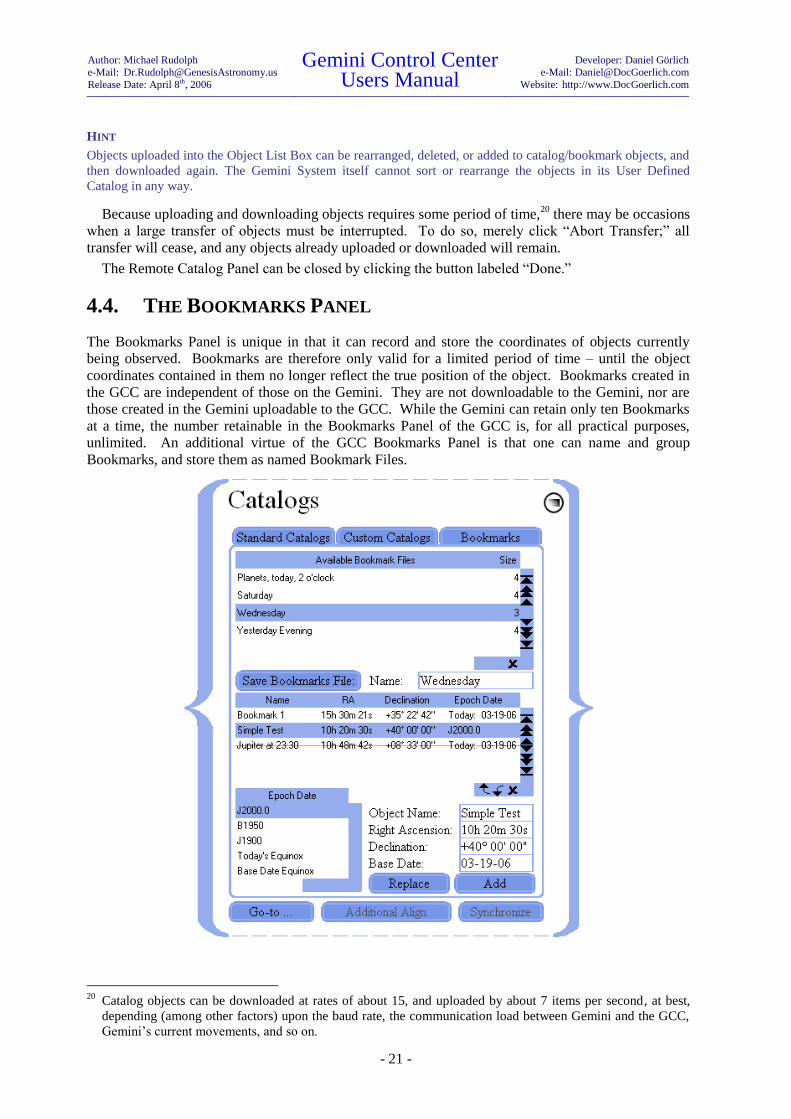
Author: Michael Rudolph
e-Mail: [email protected]
Release Date: April 8th, 2006
Gemini Control Center Users Manual
Developer: Daniel Görlich
e-Mail: [email protected]
Website: http://www.DocGoerlich.com
- 21 -
HINT
Objects uploaded into the Object List Box can be rearranged, deleted, or added to catalog/bookmark objects, and
then downloaded again. The Gemini System itself cannot sort or rearrange the objects in its User Defined
Catalog in any way.
Because uploading and downloading objects requires some period of time,20
there may be occasions
when a large transfer of objects must be interrupted. To do so, merely click “Abort Transfer;” all
transfer will cease, and any objects already uploaded or downloaded will remain.
The Remote Catalog Panel can be closed by clicking the button labeled “Done.”
4.4. THE BOOKMARKS PANEL
The Bookmarks Panel is unique in that it can record and store the coordinates of objects currently
being observed. Bookmarks are therefore only valid for a limited period of time – until the object
coordinates contained in them no longer reflect the true position of the object. Bookmarks created in
the GCC are independent of those on the Gemini. They are not downloadable to the Gemini, nor are
those created in the Gemini uploadable to the GCC. While the Gemini can retain only ten Bookmarks
at a time, the number retainable in the Bookmarks Panel of the GCC is, for all practical purposes,
unlimited. An additional virtue of the GCC Bookmarks Panel is that one can name and group
Bookmarks, and store them as named Bookmark Files.
20
Catalog objects can be downloaded at rates of about 15, and uploaded by about 7 items per second, at best,
depending (among other factors) upon the baud rate, the communication load between Gemini and the GCC,
Gemini’s current movements, and so on.

Author: Michael Rudolph
e-Mail: [email protected]
Release Date: April 8th, 2006
Gemini Control Center Users Manual
Developer: Daniel Görlich
e-Mail: [email protected]
Website: http://www.DocGoerlich.com
- 22 -
The lower half of the Bookmarks Panel contains a Bookmark/Object List,21
and just below that is an
Object Coordinate Box. This box is alternatively used to display a selected Bookmark/Object (when
the Panel is in Edit Mode), or the telescope's current RA and Dec position (when the Panel is in
Position Display Mode).22
Below the Object Coordinate Box is another box labeled “Base Date.”
This box is for inputting the observation date of any object to be bookmarked or otherwise stored.
Although the date in this box defaults to the current date (mainly for bookmarks), it can be over-
written for occasions where you may want to store predicted coordinates for a future observing
session.
The upper half of the Bookmarks Panel is a list containing the Bookmark Files you have created.23
Below this are a Bookmark File Name Box and a “Save Catalog” button that function together to save,
as a named Bookmark File, the items in the Bookmark/Object List below.
HINT
Changes to the content of a Bookmark File are not automatically saved when loading another Bookmark File or
when quitting the GCC. To save these changes you must click “Save Bookmark File.”
A Bookmark operation consists of slewing to either an object or a position in space, and then
recording its current coordinates for short-term retrieval; consequently, true Bookmarks are always
recorded according to the current date (Today).
Bookmark Files are more versatile than Custom Catalogs because they can contain and slew to both
Bookmarks and non-Bookmark Objects, cataloged in any epoch. The Epoch Date Table positioned to
the left of the Object Coordinate Box permits you to select any one of the following epoch dates for
each object:24
J2000.0
B1950
J1900
Today
Base Date Equinox
HINT
Epoch dates set in the Bookmarks Panel are independent of the Epoch Date setting in the Manual Control
Screen.
4.4.1. CREATING BOOKMARKS
The first step in creating a Bookmark is to slew the telescope to the object or position to be
bookmarked. Notice that the RA and Dec coordinates of the telescope’s targeted position appear as
gray text in the Object Coordinate Box. This is because the telescope's motion has placed the
Bookmarks Panel in its Position Display Mode. Next, set the Epoch Date to “Today’s Equinox,” and
enter a name for the proposed Bookmark in the Object Name Box (If the slew was to a previously
saved object, the object's name will already be there). Now click “Add,” and the Bookmark will
appear in the Bookmark/Object List, displaying its name, current coordinates, and its epoch date
21
If you have not yet entered objects and their coordinates, then this space remains blank.
22 When the Bookmarks Panel is in Edit Mode, the Object Coordinate Box receives and transfers coordinate data
from/to the other panels and open transferable screens; in this mode, data can also be typed directly into the
Object Coordinate Box. In contrast, when the Panel is in Position Display Mode, the coordinate fields of the
Object Coordinate Box track and display the current position of the telescope. <F2> toggles between Edit
Mode and Position Display Mode.
23 If none have yet been created, then this space remains blank.
24 A discussion of epoch dates is beyond the scope of this manual; for information about this subject, please
consult a basic astronomy textbook.

Author: Michael Rudolph
e-Mail: [email protected]
Release Date: April 8th, 2006
Gemini Control Center Users Manual
Developer: Daniel Görlich
e-Mail: [email protected]
Website: http://www.DocGoerlich.com
- 23 -
“Today.” By repeating this procedure, you can create multiple Bookmarks that can be saved in a
single Bookmark File.
HINT
When in Position Display Mode, the Object Coordinate Boxes are grayed out and cannot be edited, as can be
seen on the following screenshot. If you want to switch to Edit Mode, press <F2>!25
4.4.2. ENTERING NON-BOOKMARK OBJECTS
As previously stated, Bookmark Files can contain, and be used to slew to, both Bookmarks and non-
Bookmark Objects cataloged in any epoch. For example, a single Bookmark File can contain a nebula
bookmarked today, a star precessed to the equinox of next Thursday, a planet precessed to 3:00 A.M.
next Friday, another star whose coordinates were listed in a 1970 publication (Epoch B1950), and still
another star whose coordinates came from a recently published catalog (Epoch J2000.0). The GCC
corrects for each of these situations, as necessary for accurate pointing.
The coordinates of a non-Bookmark Object are entered in the Object Coordinate Box either
manually or by direct transfer from one of the “object-transferable” panels or screens. When entering
coordinates manually, the Bookmarks Panel must be in its Edit Mode (the RA and Dec entry boxes not
grayed). If it is not already in Edit Mode, pressing <F2> on your computer will place it there. After
entering the requisite coordinates, click “Add,” and the non-Bookmark Object will appear in the
Bookmark/Object List along with all Bookmarks and other objects previously entered.
4.4.3. RETRIEVING AND SLEWING TO BOOKMARKS AND NON-BOOKMARK
OBJECTS
Bookmark Files that have been previously saved automatically appear in the Bookmark File List
whenever the Bookmarks Panel is open. To display the Bookmarks and other objects contained in a
Bookmark File, select it; its contents will immediately be visible in the Bookmark/Object List.
To slew to a Bookmark or non-Bookmark Object, simply select the item from the Bookmark/Object
List and click “Go-to.” The Bookmarks Screen immediately goes into its Position Display Mode, and
the Object Coordinate Box displays the telescope’s changing position as the telescope moves and
comes to rest.
4.4.4. STORING NEAR OBJECTS IN A BOOKMARK FILE
On occasion, an observer may want to include a near (e.g. solar system) object in a Bookmark File for
the purpose of observing it at a future date and time. This is accomplished in a similar way as
previously described for a Custom Catalog:
1. Open the Catalogs Screen and display the Bookmarks Panel; if it is not already in Edit Mode,
put it there by pressing <F2> on your computer.
2. Open the Near Objects Screen;
25
Pressing <F2> toggles between Position Display Mode and Edit Mode.

Author: Michael Rudolph
e-Mail: [email protected]
Release Date: April 8th, 2006
Gemini Control Center Users Manual
Developer: Daniel Görlich
e-Mail: [email protected]
Website: http://www.DocGoerlich.com
- 24 -
3. Select the near object of interest;
4. Enter the expected date and time of observation in the Base Date Box and the Base Time Box;
5. Click “Copy Coordinates;”
6. Note that the object of interest with its J2000.0-converted coordinates has been accurately
transferred to the Object Coordinate Box of the Bookmarks Panel;
7. Name the Bookmark of the selected object;
8. Select Epoch Date J2000.0;
9. Click “Add.” The selected near object will appear in the Bookmark/Object List along with its
J2000.0-converted coordinates. After you are finished adding other objects, save the list as a
Bookmark File by naming it and clicking on “Save Bookmark File.”

Author: Michael Rudolph
e-Mail: [email protected]
Release Date: April 8th, 2006
Gemini Control Center Users Manual
Developer: Daniel Görlich
e-Mail: [email protected]
Website: http://www.DocGoerlich.com
- 25 -
5. THE NEAR OBJECTS SCREEN
OVERVIEW
The Near Objects Screen is launched from the Observation menu on GCC’s Main Screen by clicking
“Near Objects.”
Near objects are those celestial objects that reside within our solar system; they include the sun, the
nine planets and their moons, asteroids, etc. Because these objects are comparatively close to Earth,
their positions relative to the celestial sphere change more rapidly over short periods of time than those
of deep space objects such as stars (the term for this is “proper motion”). For that reason, the RA and
Dec positions of Near Objects are not included in standard catalogs, but can be mathematically
calculated for particular dates and times. The tabulated loci of these computed positions are known as
ephemerides (singular: “ephemeris”).
The Near Objects Screen provides a convenient way to locate and slew to the most common of the
Near Objects – the sun, eight planets,26
and Earth’s moon. Each of their coordinates can be computed
to any date and time (hereinafter called “Base Date” and “Base Time”) expressed in either local or
UTC time.
5.1. SETTING THE BASE DATE AND TIME
The Near Objects Screen contains a “Base Date” box, a “Base Time” box, and an “Entered as UTC
time” checkbox. When the Near Objects Screen is first opened, the displayed Base Date and Base
Time conform to the PC’s current date and time. A different Base Date and Base Time can be entered
but, when the UTC checkbox is checked, the Base Date and Base Time must be entered in UTC, and
when unchecked, they must be entered in local time. The importance of entering a correct Base Date
and Time is that the coordinates of Near Objects change radically with time.
The date and time of interest (expressed in either local or UTC time) are entered in the Base Date
and Time boxes by merely typing them in, making sure that the UTC checkbox is checked or
unchecked appropriately. This enables the observer to determine the expected position of any listed
near object at a given date and time for future observations. The most common need, however, is to
26
Although Earth is listed among the near objects, its inclusion serves no function other than to complete the
planet list.

Author: Michael Rudolph
e-Mail: [email protected]
Release Date: April 8th, 2006
Gemini Control Center Users Manual
Developer: Daniel Görlich
e-Mail: [email protected]
Website: http://www.DocGoerlich.com
- 26 -
determine the position of an object at the very time of an observation. This can conveniently be
accomplished by clicking the button labeled “Current Date & Time.” When this is done, the current
local date and time (according to the computer’s settings) appear in the Base Date and Base Time
boxes, and the UTC checkbox is automatically unchecked.
5.2. DETERMINING A NEAR OBJECT’S POSITION
Each listed object appears alongside a display of its RA and Dec coordinates. These coordinates are
computed for whatever date and time appear in the Base Date and Base Time boxes, and are displayed
with a “strike-through” if the object is currently below the horizon (Below Horizon Advisory)!
As previously stated, when the Near Objects Screen is first opened, the displayed Base Date and
Base Time conform to the PC’s current date and time. If you desire to know an object’s coordinate
position at a date and time other than the current one, you can enter that date and time in the Base Date
and Base Time boxes, thereby causing all listed ephemeredes to instantly update. Once displayed,
ephemerides do not update automatically, so you must click the “Current Date & Time” button each
time an update is desired.
HINT
The “strike-through” (Below Horizon Advisory) feature of the Near Object Screen responds to the date and time
setting of the PC, and is independent of the date and time in the Base Date and Base Time boxes. To illustrate, if
the user, at 22:00 local time today, calculates what the sun’s position will be at noon a month from now, the sun
will appear to be below the horizon (struck through) in the Near Object Screen even though the Base Time is set
to noon!
5.3. SLEWING TO A NEAR OBJECT
To slew to an object listed in the Near Objects Screen, select it from the object list, click the “Current
Date & Time” button, and then click “Go-to.” The telescope will slew to the object's current position
provided the correct date and time have been entered. If desired, you can then center the object in the
telescope’s field of view and click “Synchronize;” doing this temporarily assures that, if you move the
telescope away from the object, Gemini’s Go-to can re-center it.27
5.4. COPYING COORDINATES TO OTHER SCREENS
To copy a near object's coordinates to one or more object-transferable screens of the GCC (those that
contain Object Coordinate boxes), first open the screen or screens you wish to copy to and then select
the near object in the Near Object Screen that you wish to transfer. The transfer will be instantaneous.
Alternatively, if the near object you wish to transfer is already selected but the screen or screens you
wish to copy to are not yet open, you can open them and click “Copy Coordinates,” or select the near
object a second time.
5.5. MOON PHASE DISPLAY
For convenience, the Near Objects Screen displays the phase of the moon both pictorially and
numerically. To determine the phase of the moon on a given base date & time, just enter both of them
into their respective edit fields.
27
Synchronizing on a Near Object is useful only if done immediately after centering the object in the
telescope’s field of view. Since synchronization on Near Objects loses its accuracy over time, repeated
centering and synchronizing, as needed, is recommended.
Author: Michael Rudolph
e-Mail: [email protected]
Release Date: April 8th, 2006
Gemini Control Center Users Manual
Developer: Daniel Görlich
e-Mail: [email protected]
Website: http://www.DocGoerlich.com
- 27 -
5.6. STORING NEAR OBJECTS IN CUSTOM CATALOGS,
BOOKMARK FILES AND OBSERVATION SCHEDULES
As already stated, near objects are not included in standard catalogs because of the date and time
dependence of their coordinates. There are, however, times when it is useful to create temporary
Custom Catalogs, Bookmark files or Observation Schedules that include one or more near objects.
Such would be the case when planning for a particular evening’s observation at a pre-determined time.
For details on how to accomplish this, see the pertinent sections of the Catalogs Screen and
Observation Schedules Screen in this manual.

Author: Michael Rudolph
e-Mail: [email protected]
Release Date: April 8th, 2006
Gemini Control Center Users Manual
Developer: Daniel Görlich
e-Mail: [email protected]
Website: http://www.DocGoerlich.com
- 28 -
6. THE OBSERVATION SCHEDULES SCREEN
OVERVIEW
The Observation Schedules Screen is launched from the Observation menu on GCC’s Main Screen by
clicking “Schedules.”
The primary function of this screen is to allow the user to schedule a succession of automatic slews
to designated celestial objects at specifically set times. This function, sometimes called “scripting,” is
particularly useful for imaging a succession of objects over the course of an evening when a telescope
control operator is not in constant attendance. For convenience, a manual slew override and an
audible time alarm are provided, and multiple schedules can be named, saved, and deleted.
6.1. CONSTRUCTING AN OBSERVATION SCHEDULE
An Observation Schedule consists of one or more Observation Events. An Observation Event, in turn,
consists of a named object, its RA and Dec coordinates, the time that the telescope is programmed to
slew to that object, and the status of the Event. An object and its J2000.0 coordinates may either be
typed directly into the boxes provided, or copied from other object-transferable screens. This is done
by selecting the object in the other screen while the Observation Schedules Screen is open. The local
time that the slew is to occur is then typed into the box labeled “Slew Time.” Finally, the “Add”
button is clicked, causing the Observation Event to be listed as a line in the Observation Schedule, and
its status to be marked “queued.” This procedure is repeated for each Observation Event listed in the
Schedule.
Author: Michael Rudolph
e-Mail: [email protected]
Release Date: April 8th, 2006
Gemini Control Center Users Manual
Developer: Daniel Görlich
e-Mail: [email protected]
Website: http://www.DocGoerlich.com
- 29 -
HINT
Queued objects and their coordinates are subject to the same Below Horizon Advisory as described for Custom
Catalogs; the “strike-through” of this feature is triggered by the PC’s current time – not by the input Slew Time.
Since scheduled or scripted slews typically occur when there is no control operator present, the last
Event entered in a schedule should park the telescope in the Startup Position.28
This is accomplished
by entering the Slew Time for when parking should occur, and clicking “Schedule Parking.”
HINT
The Observation Schedule responds to the local time of the PC. Ideally, the PC’s and Gemini’s times are
perfectly synchronized. This can be achieved using a GPS receiver or via SNTP on the Internet; for details,
please see the chapter 11 entitled “The Synchronization Screen.”
6.2. SAVING AN OBSERVATION SCHEDULE
An Observation Schedule does not have to be saved in order to be used. Nevertheless, advanced
planning of automated slews is facilitated by being able to save one or more Schedules under separate
names.
To save a list of Observation Events as an Observation Schedule, enter a name for the Schedule in
the box labeled “Name” and click “Save Schedule as:” The named Schedule will be saved to an
Observation Schedule file and appear in the list of Available Schedules.
HINT
If the “Save Configuration” option in the Configuration Screen is checked, the current Observation Schedule will
automatically be saved to the GCC’s configuration file even if you do not save it as an Observation Schedule. It
is therefore advisable to clear the Observation Schedule when you are finished with it, in order to keep the
automatically saved configuration file from loading and possibly executing the old schedule each time the GCC
starts up.
6.3. EDITING AND DELETING OBSERVATION SCHEDULES
To edit a previously saved Observation Schedule, first select it from the list of Available Schedules.
Any Observation Event within the selected Schedule can now be replaced by (1) entering a substitute
object (name and coordinates) and Slew Time in their respective boxes, and (2) clicking “Replace.”
In addition to being replaced, Observation Events can be erased either singly or in groups. To select
a single Event for deletion, click on it in the list. To select a range of Events for deletion, click on the
first, and Shift-Click on the last. The selected Event(s) can now be deleted by clicking the delete
mark . Alternatively, all the Observation Events can be deleted at once by clicking the button
labeled “Clear Schedule.”
Observation Schedules can be deleted either singly or in groups as well. To select a single Schedule
for deletion, click on it in the list of Available Schedules. To select a range of Schedules for deletion,
click on the first, and Shift-Click on the last. The selected Schedule(s) can now be deleted by clicking
the delete mark .
6.4. ACTIVATING AND DEACTIVATING AN OBSERVATION
SCHEDULE
To activate an Observation Schedule, first select it and then enter a checkmark (by clicking) in the
checkbox labeled “Schedule activated.” When the time for an Event arrives, the Event line is marked
28
Parking the telescope disables all tracking so that an unattended telescope will not collide with its mount.

Author: Michael Rudolph
e-Mail: [email protected]
Release Date: April 8th, 2006
Gemini Control Center Users Manual
Developer: Daniel Görlich
e-Mail: [email protected]
Website: http://www.DocGoerlich.com
- 30 -
“performed,” and the telescope slews to the designated object.29
This is repeated for each Observation
Event in the Schedule.
HINT
The Slew Time entered for each Observation Event corresponds to the PC’s local time as distinguished from
Gemini’s local time. The reason for this is so that schedules can be set and tested in the GCC without having to
be online with Gemini.
If a slew cannot be performed at the time an observation is scheduled, the status of the Observation
Event is marked “FAILED.” If two or more Observation Events are scheduled for the same time, only
the first is executed; all others are marked “IGNORED.”
To deactivate the Observation Schedule at any time, uncheck the “Schedule activated” checkbox.
6.5. PERFORMING UNSCHEDULED SLEWS
Any object listed in an Observation Schedule can be slewed to prematurely by first selecting the
Schedule, then the Event within the Schedule, and finally clicking the button labeled “Make Slew.”
6.6. SETTING THE ALARM
The GCC and the Gemini System both provide the convenience of an audible time alarm to remind the
observer when an Event is about to occur or when some action has to be taken.
To set the alarm, type a local time into the “Alarm Time” input box and click the checkbox labeled
“Alarm Enabled;” this causes a checkmark to be displayed in the checkbox. When the alarm time is
reached, a notification window appears, and Gemini emits one long beep while the GCC emits several
short ones.30
HINT
Although scheduling the alarm through the GCC requires that it be online with Gemini at the time it is set, it is
Gemini’s alarm that is set; the consequence of this is that Gemini’s alarm will sound even if the GCC
subsequently goes offline. To stop that from happening, the alarm must be separately disabled using Gemini’s
Hand Controller. This feature is the reason that the alarm is set and responds to Gemini’s local time (as
distinguished from the schedules that are set and respond to the PC’s local time). Also, be sure that the GCC’s
and the Gemini’s times are synchronous; if they are not, the two alarms will sound at different times!
29
If the GCC’s connection to the Gemini is disabled when a slew is scheduled to occur, the GCC attempts to
connect in order to fulfill the scheduled task.
30 When using the alarm, set the PC’s audio volume “on.”

Author: Michael Rudolph
e-Mail: [email protected]
Release Date: April 8th, 2006
Gemini Control Center Users Manual
Developer: Daniel Görlich
e-Mail: [email protected]
Website: http://www.DocGoerlich.com
- 31 -
7. THE OBSERVATION LOGS SCREEN
OVERVIEW
The Observation Logs Screen is launched from the Observation menu on GCC’s Main Screen by
clicking “Logs & Diaries.”
Gemini creates a coded log of the major actions it performs. Each line of the log consists of the
date and time of the action, a short description of it, and an RA and Dec coordinate where applicable
(the GCC adds item numbers as well). Gemini’s Log cumulates data, action-by-action, until it
becomes filled, or the user clears it manually. The GCC can upload, display, and save Gemini’s Log to
a named Log File for future retrieval and analysis.
HINT
Uploading and clearing Gemini’s Log requires, at least, Gemini Level 2. However, independently of the
Gemini’s level, and its state of connection, the GCC can handle and edit saved log files.
The GCC can also create an Observation Diary, in plain-language text, that can be saved, and later
retrieved and edited using a text editor or word processing software.
Finally, the GCC can generate a Position Log that, each second, records and saves to a file, the UTC
date, UTC time, Sidereal time, and the telescope’s pointing coordinates (both equatorial and
horizontal). What is more, the user is able to mark the log whenever he or she desires, thereby
providing a means to reconstruct the position and time (to within one second of accuracy) when a
celestial object or event was observed.
7.1. GEMINI’S LOG AND THE GCC’S LOCAL LOG
To properly use the Observation Logs Screen, it is essential to distinguish between the terms
“Gemini’s Log” and “Local Log.” Gemini’s Log is the log code that Gemini generates internally,
Author: Michael Rudolph
e-Mail: [email protected]
Release Date: April 8th, 2006
Gemini Control Center Users Manual
Developer: Daniel Görlich
e-Mail: [email protected]
Website: http://www.DocGoerlich.com
- 32 -
which can be uploaded to the GCC. Once uploaded and interpreted into plain language, it becomes
known as Gemini’s “Local Log.”
Since Gemini’s Log cumulates data until it is cleared manually, if you want to start it from scratch,
click “Clear Gemini’s Log.” Gemini’s Log then grows, action-by-action; its data is not visible to you,
however, until you upload it to the GCC.
To upload and display Gemini’s Log interpreted into plain language (not in its abbreviated syntax),
click “Upload Gemini’s Log.” 31
The uploaded log, now termed the “Local Log,” appears in the
“Local Log List” at the bottom of the screen; it is not, as of yet, saved to a Log File.
HINT
You should normally clear the Local Log before performing an upload. If you do not, Gemini’s uploaded log
will be appended to what is already in the list.
7.1.1. INSPECTING, SAVING, AND CLEARING THE LOCAL LOG
You can now inspect the Local Log (Gemini’s uploaded log) that is displayed in the Local Log List,
and either clear it from the list or save it. The Local Log is easy to read because the GCC interprets
Gemini’s code, and displays its data in plain language under the captions “No.” (item number), “Date”
(UTC), “Time” (UTC), “Action,” “RA,” and “Dec.”
To clear the Local Log, click “Clear Local Log;” to save it to a Log File, type a name for the file
into the Name edit box, and click “Save Local Log as”: The saved Local Log will immediately appear
in the Saved Log Files list; now, if you clear the Local Log, Gemini’s Log data that was saved in the
Log File, will not be lost.
7.2. LOG FILES
A Log File is a saved Local Log. All saved Local Logs are stored in the GCC’s “Databases”
subdirectory as plain-text Log Files with “.log” extensions. From there, they may be opened, viewed,
or printed, using a text editor or a word processor.
To retrieve a Log File, simply select it in the Saved Log Files list; its contents are instantly
displayed in the Local Log List. To delete a Log File, select it in the Saved Log Files list, and click
the delete mark .
7.2.1. INTERPRETING LOG FILES
Gemini’s Log is produced by the Gemini device itself; its syntax is:
yymmddhhmmss&hh:mm:ssdd:mm:ss&#, where:
yymmdd is the UTC date
hhmmss is the UTC time
$ is a letter character representing one of the following Gemini operations:
A … Additional Align
C … Cold Start
F … Meridian Flip (requires Gemini Level 4)
D … Realign (first Initial Align after a Warm Restart)
G … Go-to operation
H … Alt/Az Object Selection (requires Gemini Level 4)
P … Primary (Initial) Align
31
Gemini’s Log is not cleared by this upload procedure.

Author: Michael Rudolph
e-Mail: [email protected]
Release Date: April 8th, 2006
Gemini Control Center Users Manual
Developer: Daniel Görlich
e-Mail: [email protected]
Website: http://www.DocGoerlich.com
- 33 -
O … Power Off
R … Warm Restart
s … Synchronize
S … Object Selection
W … Warm Start
hh:mm:ss is Right Ascension (hours, minutes & seconds).
dd:mm:ss is Declination (degrees, arc minutes, arc seconds).
& is an object name up to 10 characters long (in S and G operations only).
“GCCGoto” identifies a slew to an unnamed destination via the Manual Control Screen.
“GCCGoto Alt/Az” analogously identifies a slew to the given Altitude & Azimuth coordinate.
# is the line termination character.
When Gemini’s Log is uploaded to the GCC’s Local Log and then saved as a Log File, its
terminology and syntax are preserved, but with some additions. Chief among these additions is
“GCCGoto,” a generic object name that is used when coordinates are entered by typing them, or when
slewing to an unnamed destination using the Manual Control Screen.
The following is a typical Log File viewed with a text editor:
031111195052C12:04:46+90:00:00#
031111195151G12:06:01+90:00:00#
031111195443S12:08:53+90:00:00Dubhe a UMa#
031111195459G11:03:57+61:43:48Dubhe a UMa#
031111195701S11:03:43+61:45:02Phecda UMa#
031111195709G11:54:01+53:40:23Phecda UMa#
031111195826S11:54:01+53:40:23GCCGoto#
031111195828G11:54:01+54:40:23GCCGoto#
031111195848S11:54:00+54:40:23GCCGoto#
031111195904G11:54:01+80:40:23GCCGoto#
The following is the Local Log’s display of the same data:32
No. Date Time Action RA Declination
1 Nov 11, 2003 19:50:52 Cold start 12h 04m 46s +90° 00' 00"
2 19:51:51 Goto 12h 06m 01s +90° 00' 00"
3 19:54:43 Object Selection [Dubhe 12h 08m 53s +90° 00' 00"
4 19:54:59 Goto [Dubhe a UMa] 11h 03m 57s +61° 43' 48"
5 19:57:01 Object Selection [Phecd 11h 03m 43s +61° 45' 02"
6 19:57:09 Goto [Phecda UMa] 11h 54m 01s +53° 40' 23"
7 19:58:26 Object Selection [GCCGo 11h 54m 01s +53° 40' 23"
8 19:58:28 Goto [GCCGoto] 11h 54m 01s +54° 40' 23"
9 19:58:48 Object Selection [GCCGo 11h 54m 00s +54° 40' 23"
10 19:59:04 Goto [GCCGoto] 11h 54m 01s +80° 40' 23"
The following is a line-by-line explanation of Gemini’s actions that produced the above data:
1 At 19:50:52 UTC, Gemini was cold-started from the standard startup position.
2 At 19:51:51 UTC, the telescope was slewed in RA to 12h 06m 01s by clicking the RA button in the
Manual Control Screen.
3 At 19:54:43 UTC, Dubhe was selected in the Catalogs Screen. The advance in RA is due to sidereal
tracking.
32
Notice that some of the Action entries are truncated due to a limitation in display space. This truncation also
occurs in the Log Diary display that is described in the following section, but not in diaries that have been
saved.

Author: Michael Rudolph
e-Mail: [email protected]
Release Date: April 8th, 2006
Gemini Control Center Users Manual
Developer: Daniel Görlich
e-Mail: [email protected]
Website: http://www.DocGoerlich.com
- 34 -
4 At 19:54:59 UTC, the Catalog Screen’s Go-to button was clicked, slewing the telescope to Dubhe, at
the coordinates indicated.
5 At 19:57:01 UTC, Phecda was selected in the Catalogs Screen.
6 At 19:57:09 UTC, the Catalog Screen’s Go-to button was clicked, slewing the telescope to Phecda, at
the coordinates indicated.
7 At 19:58:26 UTC, a new declination of +54˚ 40' 23", was typed into the Manual Control Screen’s Object
Coordinate Box. The log does not reflect this because the telescope has not yet moved.
8 At 19:58:28 UTC, the Manual Control Screen’s Go-to Destination button was clicked, slewing the
telescope to declination +54˚ 40' 23".
9 At 19:58:48 UTC, a new declination was typed into the Manual Control Screen’s Object Coordinate
Box.
10 At 19:59:04 UTC, the Manual Control Screen’s Go-to Destination button was clicked, slewing the
telescope to declination +80˚ 40' 23".
7.3. OBSERVATION DIARIES
The Observation Diary Screen is launched from the Observation Logs Screen by clicking “Create
Observation Diary.” Immediately upon opening, an Observation Diary displays the same data that is
contained in the Local Log.
Visually, Observation Diaries are very similar to Local Logs; their differences are: (1) comments
can be added to, or deleted from, each diary entry; (2) diary entries can be rearranged, renumbered or
deleted; (3) Observation Diaries are saved as plain language ASCII text files;33
(4) Observation
Diaries are saved with a complete header, as illustrated in the example in 7.3.2.
33
Log Files are saved as lines of coded abbreviations, whereas Diary Files are saved in plain language and in
ASCII text format. This makes them more intuitively comprehendible, and easier to edit with a text editor or
word processor. Once in this format they cannot, however, be loaded or further processed by the GCC.

Author: Michael Rudolph
e-Mail: [email protected]
Release Date: April 8th, 2006
Gemini Control Center Users Manual
Developer: Daniel Görlich
e-Mail: [email protected]
Website: http://www.DocGoerlich.com
- 35 -
Closing an Observation Diary causes it to be lost along with any changes that were made to it. Of
course, Diary Files that are saved before the Diary is closed are preserved.
HINT
The Observation Diary Screen is not restored at startup the way the GCC’s other screens are. Also, deleting the
last entry from a Diary causes the screen to close automatically.
7.3.1. INITIAL EDITING AND DELETING OF DIARY ENTRIES
To add a comment to a Diary entry line, select the line, type your comment into the Comment edit
box, and click “Set Comment.” Your comment will be added to the end of the entry. To replace a
comment with another, type the replacement into the Comment edit box and repeat the foregoing
process. To delete a comment from an entry, select the entry line containing the comment to be
deleted, clear the Comment edit box, and click “Set Comment.” To delete all added comments, click
“Delete All Comments.”
HINT
The user can select multiple entries in the diary, and click “Set Comment” to append the same comment to all
those entries at once!
Entire Diary entry lines can be rearranged, deleted, and renumbered. To move one or more Diary
entry lines up or down on the list, select the line or lines to be moved, and then click the up or down
“move” arrows until the selected line or lines are in the position desired. To delete an entry line
(including its comments), select it and click the delete mark . Both of these procedures result in
lines being out of numerical order so, to restore their numerical order, click “Renumber Entries.”
Finally, to cancel all changes made to a Diary and return it to its original state, click “Rebuild Diary.”
HINT
Only one Observation Diary can be edited at a time.
7.3.2. SAVING AND EDITING DIARY FILES
After performing initial edits as described in the preceding section, the resulting Observation Diary
can be saved as a plain language text file into any folder on your PC. To do so, enter a filename, a
name extension (if desired), a complete path to the folder (e.g. “C:\Diaries\Log123.txt”), and then
click “Export Diary.”
HINT
Although any extension or no extension may be used for Diary Files, it is recommended that you do not use
extensions recognized by the GCC for other purposes. “.txt” is a recommended extension because it is
universally recognized to identify text files and, double-clicking a “.txt” file, will automatically launch your
default text editor.
Once an Observation Diary has been saved, its file can be opened and fully edited by any text editor
or word processor (but not by the GCC). This capability is particularly convenient when you need to
reformat your Observation Log for publication or transmission to others.
The Observation Diary can also be the source of coordinate date that you can “cut and paste” into
the Object Coordinate Box of a Custom Catalog, a Bookmark File, or an Observation Schedule.
Coordinate data can also be cut and pasted into the Object Coordinate Box of the Manual Control
Screen to enable immediate slewing to the recorded object.
The following is an example of a Diary File, with comments added, and using the same observation
data as previously presented:

Author: Michael Rudolph
e-Mail: [email protected]
Release Date: April 8th, 2006
Gemini Control Center Users Manual
Developer: Daniel Görlich
e-Mail: [email protected]
Website: http://www.DocGoerlich.com
- 36 -
Gemini Observation Diary
Created by user "Michael Rudolph" on "MY PC."
Date: Nov 14, 2003
Created by Gemini Control Center L4
Copyright (C) 2003-2006 by Daniel Görlich
Contact: [email protected]
Website: http://www.DocGoerlich.com/Daniel/
No. Date Time Action RA Dec Comment
1 Nov 11, 2003 19:50:52 Cold start 12h04m46s +90°00'00"
3 19:54:43 Object Selection [Dubhe a UMa] 12h08m53s +90°00'00"
4 19:54:59 Goto [Dubhe a UMa] 11h03m57s +61°43'48" Very nice
5 19:57:01 Object Selection [Phecda a UMa] 11h03m43s +61°45'02"
6 19:57:09 Goto [Phecda UMa] 11h54m01s +53°40'23" Revisit!!
9 19:58:48 Object Selection [GCCGoto] 11h54m00s +54°40'23"
10 19:59:04 Goto [GCCGoto] 11h54m01s +80°40'23"
Note to myself: Transparency was clear, and seeing was moderate to good. Equipment was 11-inch SC on
Losmandy G-11 mount, with L3 Gemini. Lines 2, 7 and 8 of the diary were deleted as being uninteresting,
and therefore unnecessary to preserve.
7.4 POSITION LOGS
The GCC’s Position Log is a record of the telescope’s pointing coordinates with respect to time, and a
means for marking the record the moment the user observes a celestial object or event that is of special
interest and to which he or she wants to return. The Position Log is managed from the Position Log
Screen which is, in turn, launched from the Observation Log Screen by clicking the button labeled
“Create Position Log.”

Author: Michael Rudolph
e-Mail: [email protected]
Release Date: April 8th, 2006
Gemini Control Center Users Manual
Developer: Daniel Görlich
e-Mail: [email protected]
Website: http://www.DocGoerlich.com
- 37 -
7.4.1 CREATING A POSITION LOG FILE
The first step in creating a Position Log file is to give it a file name with an extension of your choice
(e.g. “December 17.txt”).34
The file’s name preceded by its full target path location on the PC (e.g.
“c:\GCC Log Files\December 17.txt”), are typed into the File Name Input Box of the Position Log
Screen, and the button labeled “Apply” is clicked. When this is done, “Status: Not recording” is
displayed, indicating that the Position Log is ready to be used, but is not yet activated. For
convenience, the file name and its path are remembered by the GCC so that you will not have to re-
type them each time the GCC is launched; they can, of course, be changed at any time.
HINT
Upon exiting the GCC, the Position Log file name is saved into the GCC’s configuration file provided that “Save
settings at program termination” is checked in the Configuration Screen. If it is, the Position Log file name will
be restored (re-entered) in the File Name Input Box of the Position Log Screen when the GCC starts up the next
time, but recording will not automatically begin.
ANOTHER HINT
If the file name and path are accepted by the GCC, the message “File name validated” will appear below it; if
not, the former message inviting entry of a file name and path will continue to be displayed. If the name and
path entered or remembered is a duplicate of one that already exists, the message “Warning: This file already
exists.” will appear. If you choose to use an existing file name and path, any position data subsequently recorded
will be appended to the existing data stored in the file.
7.4.2 ACTIVATING THE POSITION LOG
To begin recording the Position Log, either click “Activate,” or type Ctrl-P on the PC’s keyboard; the
status message changes from “Not recording” to “Recording,” and the “Activate” button changes to
“Deactivate.” While it is recording, the Position Log generates a line of data (consisting of date, time,
and telescope pointing coordinates) every second. When the “Deactivate” button is clicked (or Ctrl-P
is typed) all recording ceases, the log is saved, the “Deactivate” button reverts to “Activate,” and the
status message changes back to “Not recording.” If the Position Log file is not deleted from its
Windows folder, each subsequent activation causes additional lines of data to be appended to those
that already exist.
HINT
Once a Position Log file (with its full path) has been defined and “Applied” via the Position Log Screen, typing
Ctrl-P from any location of the GCC, causes the Position Log to begin recording and “(logging)” to be displayed
on the Real-Time Status Screen. Typing Ctrl-P again, stops the recording, and “(logging)” disappears from the
Status Screen; recording the Position Log can be started and stopped many times by repeatedly typing Ctrl-P.
ANOTHER HINT
To begin a new Position Log, either delete the old log file or enter a new file name and path in the Position Log
Screen’s File Name box. Position Log files cannot be deleted from within the GCC; to delete a Position Log
file, the user must locate it in the Windows folder where it resides, and delete it using a Windows delete
command.
7.4.3 MARKING THE POSITION LOG
One of the most powerful capabilities of the Position Log is its ability to be “Marked” on the fly by the
user, thereby preserving the time and position (within 1 second of accuracy) that a celestial object or
event is observed through the telescope.
34
The file extension “.txt” is recommended because it is universally recognized to identify text files and, double-
clicking a “.txt” file, will automatically launch your default text editor.

Author: Michael Rudolph
e-Mail: [email protected]
Release Date: April 8th, 2006
Gemini Control Center Users Manual
Developer: Daniel Görlich
e-Mail: [email protected]
Website: http://www.DocGoerlich.com
- 38 -
A Position Log, during the time it is activated, generates and saves a line of data each second, and
any of these lines can be marked, either by clicking “Mark Coordinates” in the Position Log Screen, or
typing Ctrl-R from any screen of the GCC. Performing either of these actions, stamps the word
“Marked” in the right margin of the currently generated line of data.
There is even greater capability built into the GCC, in that the user can mark and record the
telescope’s coordinates the instant of an observed event even when the Position Log is not actively
recording. As long as there is a Position Log file name and path entered in the Position Log Screen, a
“Marked” line displaying date, time, and position is generated and saved in the named Position Log
every time Ctrl-R is typed.
HINT
If a Position Log is not actively recording when Ctrl-R is typed or “Mark Coordinates” is clicked, “(logging)”
appears momentarily in the Real-Time Status Screen. Because you never know when you will want to start
recording a Position Log, it is prudent to always maintain a Position Log file name and path in the Position Log
Screen.
7.4.4 VIEWING THE POSITION LOG
The Position Log cannot be viewed from the GCC. To view a Position Log file, locate and open it in
the Windows folder wherein it resides. If the file’s extension is “.txt,” it will open and be displayed in
Windows’ default text editor (e.g. Notepad).
Reading from left to right, each line of the Position Log contains the following data:
UTC Date (mm-dd-yyyy)
UTC Time (hh:mm:ss)
Right Ascension (hh mm ss)
Declination (±dd° mm' ss")
Azimuth (ddd° mm' ss")
Altitude (±dd° mm' ss")
Sidereal Time (±hh mm ss)
“Marked” if marked
HINT
The Azimuth and Altitude fields are left blank if the Gemini System connected is an earlier version than Level 4.
An example of a typical Position Log is illustrated below.
12-16-2005|20:57:54|20h 47m 40s|-09° 29' 45"|051° 16' 14"|+30° 16' 10"|+02h 52m 21s
12-16-2005|20:57:55|20h 47m 40s|-09° 29' 45"|051° 16' 14"|+30° 16' 10"|+02h 52m 22s
12-16-2005|20:57:56|20h 47m 40s|-09° 29' 45"|051° 16' 14"|+30° 16' 10"|+02h 52m 23s
12-16-2005|20:57:57|20h 47m 40s|-09° 29' 45"|051° 16' 14"|+30° 16' 10"|+02h 52m 24s
12-16-2005|20:57:58|20h 47m 40s|-09° 29' 45"|051° 17' 07"|+30° 15' 32"|+02h 52m 25s Marked
12-16-2005|20:57:59|20h 47m 40s|-09° 29' 45"|051° 17' 07"|+30° 15' 32"|+02h 52m 26s
12-16-2005|20:58:00|20h 47m 40s|-09° 29' 45"|051° 17' 07"|+30° 15' 32"|+02h 52m 27s
12-16-2005|20:58:01|20h 47m 40s|-09° 29' 45"|051° 17' 07"|+30° 15' 32"|+02h 52m 28s
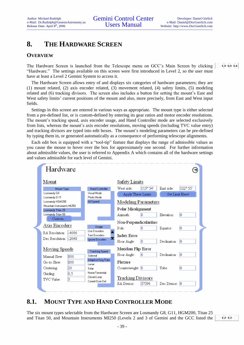
Author: Michael Rudolph
e-Mail: [email protected]
Release Date: April 8th, 2006
Gemini Control Center Users Manual
Developer: Daniel Görlich
e-Mail: [email protected]
Website: http://www.DocGoerlich.com
- 39 -
8. THE HARDWARE SCREEN
OVERVIEW
The Hardware Screen is launched from the Telescope menu on GCC’s Main Screen by clicking
“Hardware.” The settings available on this screen were first introduced in Level 2, so the user must
have at least a Level 2 Gemini System to access it.
The Hardware Screen allows entry of and displays six categories of hardware parameters; they are
(1) mount related, (2) axis encoder related, (3) movement related, (4) safety limits, (5) modeling
related and (6) tracking divisors. The screen also includes a button for setting the mount’s East and
West safety limits’ current positions of the mount and also, more precisely, from East and West input
fields.
Settings in this screen are entered in various ways as appropriate. The mount type is either selected
from a pre-defined list, or is custom-defined by entering its gear ratios and motor encoder resolutions.
The mount’s tracking speed, axis encoder usage, and Hand Controller mode are selected exclusively
from lists, whereas the mount’s axis encoder resolutions, moving speeds (including TVC value entry)
and tracking divisors are typed into edit boxes. The mount’s modeling parameters can be pre-defined
by typing them in, or generated automatically as a consequence of performing telescope alignments.
Each edit box is equipped with a “tool-tip” feature that displays the range of admissible values as
you cause the mouse to hover over the box for approximately one second. For further information
about admissible values, the user is referred to Appendix A which contains all of the hardware settings
and values admissible for each level of Gemini.
8.1. MOUNT TYPE AND HAND CONTROLLER MODE
The six mount types selectable from the Hardware Screen are Losmandy G8, G11, HGM200, Titan 25
and Titan 50, and Mountain Instruments MI250 (Levels 2 and 3 of Gemini and the GCC listed the
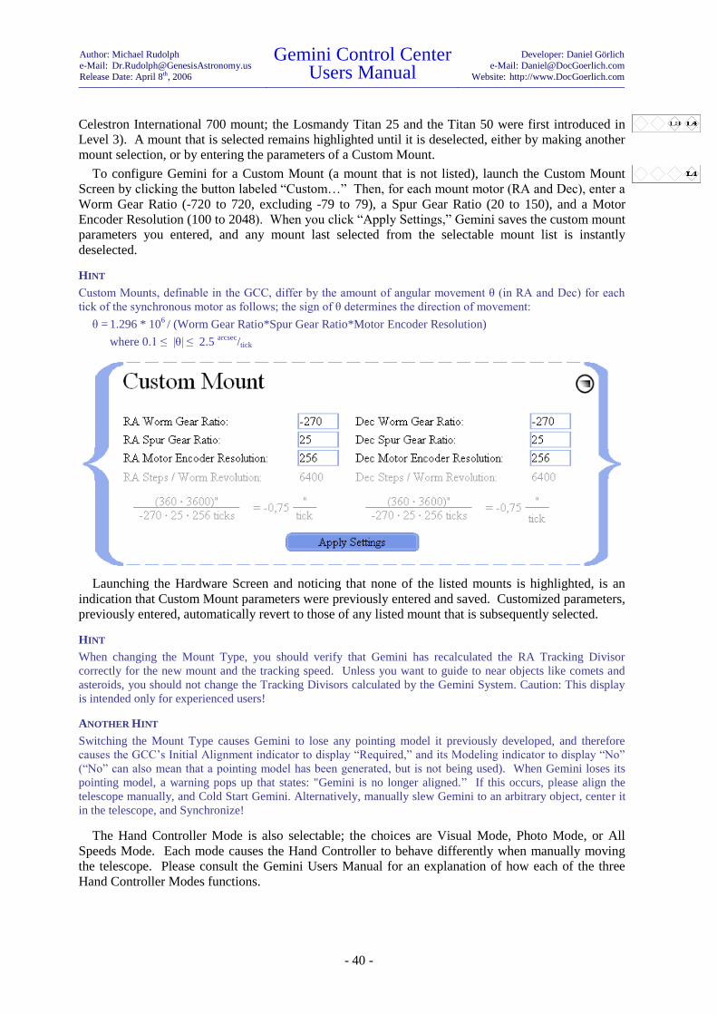
Author: Michael Rudolph
e-Mail: [email protected]
Release Date: April 8th, 2006
Gemini Control Center Users Manual
Developer: Daniel Görlich
e-Mail: [email protected]
Website: http://www.DocGoerlich.com
- 40 -
Celestron International 700 mount; the Losmandy Titan 25 and the Titan 50 were first introduced in
Level 3). A mount that is selected remains highlighted until it is deselected, either by making another
mount selection, or by entering the parameters of a Custom Mount.
To configure Gemini for a Custom Mount (a mount that is not listed), launch the Custom Mount
Screen by clicking the button labeled “Custom…” Then, for each mount motor (RA and Dec), enter a
Worm Gear Ratio (-720 to 720, excluding -79 to 79), a Spur Gear Ratio (20 to 150), and a Motor
Encoder Resolution (100 to 2048). When you click “Apply Settings,” Gemini saves the custom mount
parameters you entered, and any mount last selected from the selectable mount list is instantly
deselected.
HINT
Custom Mounts, definable in the GCC, differ by the amount of angular movement θ (in RA and Dec) for each
tick of the synchronous motor as follows; the sign of θ determines the direction of movement:
θ = 1.296 * 106 / (Worm Gear Ratio*Spur Gear Ratio*Motor Encoder Resolution)
where 0.1 ≤ |θ| ≤ 2.5 arcsec
/tick
Launching the Hardware Screen and noticing that none of the listed mounts is highlighted, is an
indication that Custom Mount parameters were previously entered and saved. Customized parameters,
previously entered, automatically revert to those of any listed mount that is subsequently selected.
HINT
When changing the Mount Type, you should verify that Gemini has recalculated the RA Tracking Divisor
correctly for the new mount and the tracking speed. Unless you want to guide to near objects like comets and
asteroids, you should not change the Tracking Divisors calculated by the Gemini System. Caution: This display
is intended only for experienced users!
ANOTHER HINT
Switching the Mount Type causes Gemini to lose any pointing model it previously developed, and therefore
causes the GCC’s Initial Alignment indicator to display “Required,” and its Modeling indicator to display “No”
(“No” can also mean that a pointing model has been generated, but is not being used). When Gemini loses its
pointing model, a warning pops up that states: "Gemini is no longer aligned.” If this occurs, please align the
telescope manually, and Cold Start Gemini. Alternatively, manually slew Gemini to an arbitrary object, center it
in the telescope, and Synchronize!
The Hand Controller Mode is also selectable; the choices are Visual Mode, Photo Mode, or All
Speeds Mode. Each mode causes the Hand Controller to behave differently when manually moving
the telescope. Please consult the Gemini Users Manual for an explanation of how each of the three
Hand Controller Modes functions.
Author: Michael Rudolph
e-Mail: [email protected]
Release Date: April 8th, 2006
Gemini Control Center Users Manual
Developer: Daniel Görlich
e-Mail: [email protected]
Website: http://www.DocGoerlich.com
- 41 -
8.2. AXIS ENCODER SETTINGS
Accessory RA and Dec axis encoders are sometimes installed to keep track of where the telescope is
pointing when it is moved by hand after the mount’s axis clutches are loosened. Encoders are
designed to operate at specific resolutions (ticks per revolution) and, for the encoders to operate
properly, Gemini must be informed of these resolutions by having them typed into their respective edit
boxes.35
When first installing axis encoders, it is useful to be able to test them by having their actual values
displayed on Gemini’s LED display. This may be accomplished by selecting “Test Encoders” from
the Encoder Usage list. Two other selectable settings in the Encoder Usage list are toggles of each
other; selecting “Use Encoders” sets your auxiliary encoders online, and selecting “Ignore Encoders”
sets them offline and inoperative even though they remain electrically connected to the Gemini, and
physically connected to the mount.
If auxiliary encoders are not used, physical limit end switches may be installed in their place to
prevent the mount from exceeding its RA limits and damaging the mount or telescope. If end switches
are installed, they may be turned on or off using the settings “Use Switches” and “Don’t use
Switches.” Selecting “All offline” disables both switches and encoders by causing them to be ignored
by the software.
Using auxiliary encoders is not recommended for Gemini levels 3 and 4 because the motor encoders
are much more precise; furthermore, slewing via the Hand Controller or the GCC is much more
precise than trying to position the telescope by hand.
8.3. MOVING SPEEDS AND TVC VALUE
There are four selectable Moving Speeds; they are: Manual Slewing, Go-to Slewing, Centering, and
Guiding. Although the selection of Moving Speed and the initiation of manual and Go-to movements
of the telescope are performed in other screens, the rates of the Moving Speeds are set in the Hardware
Screen.
HINT
The Manual Slewing Speed set in the Hardware Screen can be overridden in the Manual Control Screen.
TVC is short for “Time Variable Compensation.” Setting its value properly is essential for
eliminating the delay caused by a mount’s gear backlash when the mount’s direction of movement is
changed in Declination during guiding. When a value for TVC is entered in the appropriate edit box
in the Hardware Screen, it defines the number of steps that are made at a higher speed to overcome the
backlash quickly after a directional change.
HINT
TVC is only used for guiding speed in Photo Mode or All Speeds Mode. A TVC value is too high if you detect a
jump while changing directions in Dec. To avoid spoiling an image, choose a slightly lower value.
8.4. TRACKING SPEEDS AND TRACKING DIVISORS
There are seven selectable Tracking Speeds; they are: Sidereal, Adaptive King Rate,36
Lunar, Solar,
None/Terrestrial, Closed Loop, and Comet/User Defined. The Gemini Users Manual should be
consulted for an explanation of how each is used. Also, for further information about Gemini’s level-
dependency, you are referred to Appendix A, which contains all of the settings and values admissible
for each level of Gemini.
35
The RA and Dec encoders do not necessarily have the same resolutions.
36 Beginning with Level 3, Closed Loop and Comet/User Def. tracking were introduced, and Adaptive King
Rate replaced King Rate tracking.
Author: Michael Rudolph
e-Mail: [email protected]
Release Date: April 8th, 2006
Gemini Control Center Users Manual
Developer: Daniel Görlich
e-Mail: [email protected]
Website: http://www.DocGoerlich.com
- 42 -
Tracking Divisors define “Comet/User Defined” tracking rates.37
They are based on the RA timer
running at 1.5 MHz (1,500,000 ticks per second), and they divide this rate down to the speed at which
RA tracking must occur. Since each mount may have a different step size (e.g. the step size of the
G-8, G-11, HGM-200 and MI-250 is 0.5625 arcsec
/step, whereas the Titan mounts are different), selecting
one of the listed mounts automatically enters an RA Tracking Divisor that will cause that particular
mount to track at the sidereal rate in RA; the Dec Tracking Divisor is set to 0 to prevent tracking in
Declination.38
To calculate a mount’s RA tracking divisor, multiply 1.5 * 106 ticks
/second (Gemini’s RA timer speed)
by the mount’s step size, and divide by 15.04106865 arcsec
/second (the sidereal rate of the sky’s
movement). In the case of the above-mentioned mounts, this rounds to 56,096 ticks
/arcsec, which is the
RA tracking divisor that is displayed when you select any one of them. Then, if you change the RA
tracking divisor,39
Gemini changes its RA tracking rate accordingly, and displays “User Defined.”
The Dec tracking divisor does not have its own timer, but is an inverse multiple of the mount’s RA
tracking steps. If the divisor is set to 0, no Dec tracking occurs. Setting it to 1, lets the mount track in
Dec at the same speed as in RA. Setting it to 100 will give one Dec step per 100 RA steps; if,
therefore, the RA tracking divisor is set to track at sidereal speed, Dec will track at 1/100 of the sidereal
rate or 0.1504106865 arcsec
/second.40
HINT
Setting the Dec divisor to other than 0, causes Gemini to switch to “Comet/User Defined” tracking. The GCC
automatically retrieves divisors appropriate to any new mount that is selected; it usually hides any divisors that
are not applied to the mount’s calculations, showing only those that influence the calculation or are planned to be
integrated into Gemini's calculations in future releases.
8.5. SETTING SAFETY LIMITS
Gemini is capable of establishing Right Ascension safety limits to prevent the telescope from
accidentally tracking or slewing into the mount. These safety limits can be set in two ways:
(1) by entering the mount hour angles (degrees and minutes) of the East side and West side limits
into each of their respective input fields and clicking “Apply These Limits,” or
(2) by slewing the telescope in RA to where you want to set each limit, and clicking “Set Limit
Here!”
If, at any time in the future, the telescope tracks or slews beyond the mount hour angle that was set,
Gemini will sound an alarm, all telescope movement will stop, and the Real-Time Status Screen will
display “Yes” in the Limit Reached field. To intentionally move beyond a safety limit, simply resume
the slew; if a new safety limit is then set, the old one is cancelled. Further details on safety limits can
be found in the Gemini Users Manual.
HINT
The sum of the East and West side safety limits must be no less than 180º, nor greater than 360º. Gemini does
not perform any Go-to operations that (a) point outside of the safety limits, or (b) must move the telescope in a
way that temporarily moves it outside of the limits. Exceeding the limits is possible, however, via manual
movement performed in the GCC’s Manual Control Screen or Hand Controller Simulation Panel.
37
Comet/User Defined tracking can also be established, via Gemini’s Hand Controller, through a process of
training or coordinate entry.
38 Selecting None/Terrestrial tracking causes the tracking divisor boxes to disappear and be replaced with the
explanation: “No divisors are computed for this tracking speed.” None/Terrestrial is the only tracking speed
whereby all tracking movement of the telescope stops.
39 Manually increasing the tracking divisor leads to slower tracking.
40 The sign of the Dec divisor determines the direction of Dec tracking.

Author: Michael Rudolph
e-Mail: [email protected]
Release Date: April 8th, 2006
Gemini Control Center Users Manual
Developer: Daniel Görlich
e-Mail: [email protected]
Website: http://www.DocGoerlich.com
- 43 -
8.6. MODELING PARAMETERS
The first time a star alignment is done,41
a Gemini modeling algorithm initiates, and all internal model-
ing parameters are reset. After that, each subsequent star alignment (“Additional Align”) contributes
to the growing model, causing ever-increasing accuracy in Gemini’s ability to point to given celestial
objects or coordinates.
The following modeling parameters are uploaded from the Gemini to the GCC automatically, where
the result of each star alignment can be followed; they can also be edited in the GCC by typing in new
values:
Polar Misalignment (Azimuth and Elevation)
Non-Perpendicularities (Pole and Equator)
Index Error (Hour Angle and Declination)
Meridian Flip Error (Hour Angle and Declination)
Flexure (Counterweight and Tube)
This manual cannot go further in explaining modeling parameters except to say that the user can
save sets of modeling parameters into configuration files and retrieve them at any time. The user is
referred to the Gemini Users Manual for more information on modeling, and on performing star
alignments.
41
In Gemini Levels 1 and 2, the first alignment is the procedure known as “Initial Align.” Beginning with
Level 3, an initial alignment is done automatically when Gemini is powered on. The first star alignment is
therefore a “Synchronize,” and each subsequent alignment is an “Additional Align.”

Author: Michael Rudolph
e-Mail: [email protected]
Release Date: April 8th, 2006
Gemini Control Center Users Manual
Developer: Daniel Görlich
e-Mail: [email protected]
Website: http://www.DocGoerlich.com
- 44 -
9. THE MANUAL CONTROL SCREEN
OVERVIEW
The Manual Control Screen is launched from the Telescope menu on GCC’s Main Screen by clicking
“Manual Control.” It incorporates three selectable panels – Manual Control, Search & Focus, and
Hand Controller Emulation; each panel covers a part of the Manual Control Screen, leaving parts of
the screen visible for certain shared operations.
The Manual Control Panel has an array of directional buttons that can be used to manually move the
telescope in Right Ascension and Declination at slewing, centering or guiding speeds. It also provides
a means to reverse the direction of movement that results from clicking each button, and a means to
stop all telescope movement. The Search & Focus Panel provides a means to visually search a defined
area of the sky, to wobble the telescope for enhanced viewing, and to focus the telescope remotely.
The Hand Controller Emulation Panel duplicates Gemini’s Hand Controller, thereby allowing remote
control of even those Gemini functions that the GCC cannot otherwise access.
In addition to hosting the aforesaid three panels, the Manual Control Screen provides other
functions, including means to input and Go-to RA/Dec or Alt/Az celestial coordinates, set the epoch
date for inputting coordinates (current date or J2000.0), display the telescope’s current pointing
position in either RA/Dec or Alt/Az, set slewing speed, park and focus the telescope, adjust the Hand
Controller’s LED brightness, reboot Gemini, reset its defaults, monitor the status and progress of an
operation, and connect and disconnect the GCC from the computer’s serial port. It should be noted
that Alt/Az coordinates are only recognized by Gemini Level 4.
9.1. SETTING PARAMETERS
Several settings in the Manual Control Screen duplicate or override similar ones that appear elsewhere
in the GCC.
9.1.1. EPOCH DATE
Whereas epoch dates of Bookmarks are assigned in the Bookmarks Panel of the Catalogs Screen, two
Epoch Date choices that apply to coordinates input for manual slewing are set in the Manual Control
Screen. These two choices are J2000.0, and Today’s Equinox (equinox of the current date).

Author: Michael Rudolph
e-Mail: [email protected]
Release Date: April 8th, 2006
Gemini Control Center Users Manual
Developer: Daniel Görlich
e-Mail: [email protected]
Website: http://www.DocGoerlich.com
- 45 -
The purpose of allowing these choices of Epoch Date is to facilitate Gemini in finding and
accurately slewing to celestial objects that are input manually. For example, if a coordinate of interest
is derived from a J2000.0 catalog, then the Epoch Date of the GCC should be set for J2000.0 before
inputting and slewing to that coordinate. On the other hand, if the current coordinate of an object is
known but its J2000.0 coordinate is not (which might be the case if an object is newly discovered and
yet un-cataloged), then Today’s Equinox should be entered.
It is important to remember that the Epoch Date set in this screen affects input coordinates in Right
Ascension and Declination only. Coordinates that are input in Altitude and Azimuth are independent
of the Epoch Date set, and the coordinates of where the telescope is currently pointing are always
displayed in the equinox of the current date.
9.1.2. SLEWING SPEED OVERRIDE
Although the three moving speeds (slewing, centering and guiding) are pre-set in the Hardware
Screen, the Manual Control Screen provides a slew speed override – a means for changing the speed
of manual and Go-to slews initiated from this screen only.
Slewing speed selections can range between 1 º/s and 6
º/s of sidereal speed as follows:
n º/s = (n*240)x
where x is the sidereal speed (15 arcsec
/second), and n is an integer, 1 ≤ n ≤ 6.
9.1.3. BRIGHTNESS
The control labeled “Brightness” enables the user to select an appropriate brightness for the Gemini
Hand Controller’s LED display from a maximum of 100% to a minimum of 6.6% This is to allow
ease of viewing in various lighting conditions.
HINT
Changing the Hand Controller’s brightness has no impact on the brightness of the GCC’s displays and screens;
these can be adjusted via the monitor’s controls, by changing Windows’ display settings, or by changing the
GCC’s custom color scheme.
9.1.4. RESTORING GEMINI’S DEFAULT SETTINGS
Gemini is delivered to the user with Losmandy default settings for all essential parameters. It is
expected that the user will change Gemini’s settings to suit his or her specific needs, but there may be
times when it is convenient to restore its settings to their original default values. To restore Gemini’s
Losmandy default settings, merely click the button labeled “Reset Defaults” (see section 2.2.4 of this
manual for instructions on how to change Gemini’s settings to Mountain Instruments’ defaults from
the Advanced Options Panel).
9.2. THE MANUAL CONTROL PANEL & TELESCOPE MOVEMENTS
Although telescope movements of various kinds are controlled and performed from other GCC panels
and screens (e.g. tracking, focusing, searching, etc.), it is the Manual Control Panel from where most
of the manual movements of the telescope are executed. Also, by intention, the Manual Control Panel
does not completely cover over the larger Manual Control Screen, thereby allowing other important
and frequently used movements to be performed as well. The three principal movements of the
telescope that are executable when the Manual Control Panel is deployed are (1) manual movements,
(2) Go-to movements, and (3) parking movements.

Author: Michael Rudolph
e-Mail: [email protected]
Release Date: April 8th, 2006
Gemini Control Center Users Manual
Developer: Daniel Görlich
e-Mail: [email protected]
Website: http://www.DocGoerlich.com
- 46 -
9.2.1. MOVING THE TELESCOPE MANUALLY
The telescope may be moved manually using the four diamond-shaped directional buttons. The
horizontally placed buttons (left and right) move the telescope in Right Ascension, while the vertically
placed buttons (upper and lower) move it in Declination.
Each directional button consists of two halves. The outer half (white in color by default) operates in
touch mode (press-to-move, release-to-stop). The inner half (blue in color by default) operates in
toggle mode (press-to-move, press again to stop).
Two buttons are provided that reverse the direction of the telescope’s movement caused by each of
the directional buttons. Normally, as viewed from the south looking north, the left button moves the
telescope counterclockwise in RA and the right button moves it clockwise. Similarly, the upper button
moves the telescope counterclockwise in Dec and the lower button moves it clockwise. When
depressed, the RA REV and DEC REV buttons reverse these directions respectively.
As the telescope is moved manually, its changing position can be monitored by viewing the RA/Dec
or Alt/Az read-outs provided.
9.2.2. SELECTING A SPEED FOR MANUAL MOVEMENT
As has already been said, slewing, centering and guiding speeds are pre-set in the Hardware Screen,
and there is a Slewing Speed Override that is set in the Manual Control Screen. To select which of the
three speeds will result from pressing a directional button, the Manual Control Screen provides three
buttons labeled “S,” “C,” and “G” for selecting slewing, centering, and guiding speeds respectively.
HINT
When a Gemini level 3 or 4’s Hand Controller is set to Visual Mode, guiding is not possible. The GCC's "G"
button is therefore disabled in this mode, resulting in centering speed being set and the GCC's "C" button being
selected as a substitute. Beginning with Gemini level 4, guiding is allowed even in Visual Mode.
9.2.3. GO-TO SLEWING TO A COORDINATE
In order to slew to a specified RA/Dec coordinate expressed in either J2000.0 or the equinox of the
current date, first be sure that the Epoch Date is properly set. Then, input a Right Ascension value
(hours, minutes and seconds) in the box labeled “Target Rt. Ascension,” and a Declination value
(±degrees, minutes, and seconds) in the box labeled “Target Declination.” This input may also be
accomplished by copying the coordinate from one of GCC’s object-transferable screens. Pressing the
“Go-to Destination” button will then cause the telescope to slew to the desired target location as
confirmed by the Right Ascension and Declination position display provided.
9.2.4. PARKING THE TELESCOPE
Two Park functions are provided in Gemini Level 3 and higher; they are (1) Startup Position, and (2)
Home Position. When the Gemini is first powered up, it remembers the telescope’s initial start-up
position that it assumes to be counterweight down, pointing north. Even if that is not the case,
pressing the button labeled “Startup Position” will return the telescope to its Startup Position and turn
off all tracking. The “Home Position” button allows you to return the telescope to a pre-determined
Home Position that can be set with Gemini’s Hand Controller or through the GCC’s Hand Controller
Emulation Panel as described below. If a Home Position is not set, the “Home Position” button
defaults to slewing the telescope to the Startup Position.
HINT
Both the Startup Position and Home Position are positions of the mount’s RA and Dec axes relative to the
mount’s fixed base or tripod; they are not positions relative to celestial coordinates.
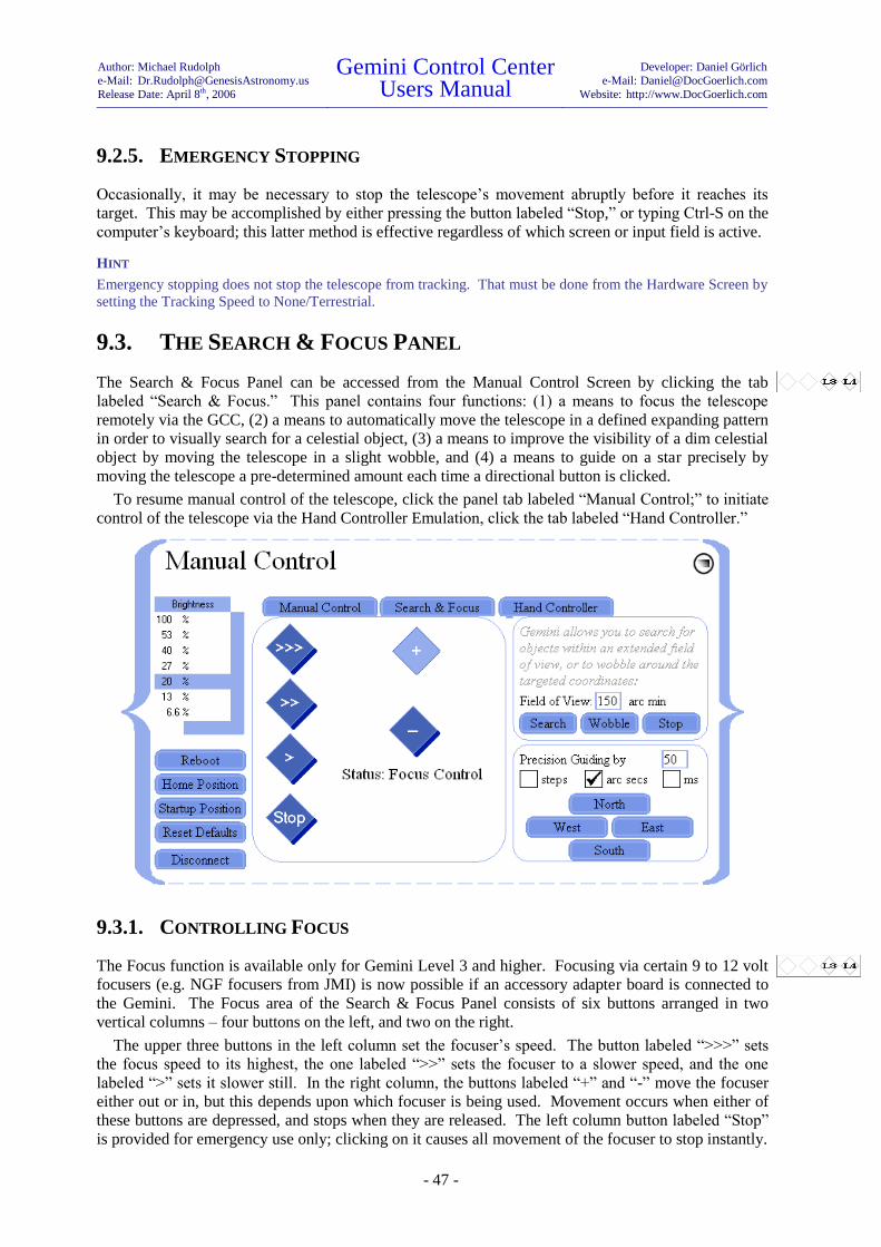
Author: Michael Rudolph
e-Mail: [email protected]
Release Date: April 8th, 2006
Gemini Control Center Users Manual
Developer: Daniel Görlich
e-Mail: [email protected]
Website: http://www.DocGoerlich.com
- 47 -
9.2.5. EMERGENCY STOPPING
Occasionally, it may be necessary to stop the telescope’s movement abruptly before it reaches its
target. This may be accomplished by either pressing the button labeled “Stop,” or typing Ctrl-S on the
computer’s keyboard; this latter method is effective regardless of which screen or input field is active.
HINT
Emergency stopping does not stop the telescope from tracking. That must be done from the Hardware Screen by
setting the Tracking Speed to None/Terrestrial.
9.3. THE SEARCH & FOCUS PANEL
The Search & Focus Panel can be accessed from the Manual Control Screen by clicking the tab
labeled “Search & Focus.” This panel contains four functions: (1) a means to focus the telescope
remotely via the GCC, (2) a means to automatically move the telescope in a defined expanding pattern
in order to visually search for a celestial object, (3) a means to improve the visibility of a dim celestial
object by moving the telescope in a slight wobble, and (4) a means to guide on a star precisely by
moving the telescope a pre-determined amount each time a directional button is clicked.
To resume manual control of the telescope, click the panel tab labeled “Manual Control;” to initiate
control of the telescope via the Hand Controller Emulation, click the tab labeled “Hand Controller.”
9.3.1. CONTROLLING FOCUS
The Focus function is available only for Gemini Level 3 and higher. Focusing via certain 9 to 12 volt
focusers (e.g. NGF focusers from JMI) is now possible if an accessory adapter board is connected to
the Gemini. The Focus area of the Search & Focus Panel consists of six buttons arranged in two
vertical columns – four buttons on the left, and two on the right.
The upper three buttons in the left column set the focuser’s speed. The button labeled “>>>” sets
the focus speed to its highest, the one labeled “>>” sets the focuser to a slower speed, and the one
labeled “>” sets it slower still. In the right column, the buttons labeled “+” and “-” move the focuser
either out or in, but this depends upon which focuser is being used. Movement occurs when either of
these buttons are depressed, and stops when they are released. The left column button labeled “Stop”
is provided for emergency use only; clicking on it causes all movement of the focuser to stop instantly.
Author: Michael Rudolph
e-Mail: [email protected]
Release Date: April 8th, 2006
Gemini Control Center Users Manual
Developer: Daniel Görlich
e-Mail: [email protected]
Website: http://www.DocGoerlich.com
- 48 -
HINT
The focusing “Stop” button only affects focusing movement. It does not stop any other movement of the
telescope.
9.3.2. SEARCHING FOR OBJECTS
This function assists you in finding a celestial object that you know or suspect is close to where the
telescope is pointing, but which you cannot see in the telescope’s field of view. To initiate a search
for the object, you enter the number of arcminutes (1 to 255) of sky you desire to search into the
“Field of Search” input box, and click “Search.” The telescope begins to move in an ever-expanding
RA and Dec pattern, starting from the telescope’s current pointing position and only stopping when
the search field has reached the designated number of arcminutes, or you click the search/wobble
“Stop” button (hopefully because you see the searched-for object passing through the telescope’s field
of view). The fineness or coarseness of the search (distance between the lines of search) is determined
by the number of search arcminutes entered.
HINT
The search/wobble “Stop” button only affects the Object Search and Telescope Wobble movements. It does not
stop any other movement of the telescope or focuser.
ANOTHER HINT
In most cases, the reason for initiating a search is that you slewed to a cataloged celestial object that should have
been visible in the telescope’s field of view, but that you were unable to see. In that case, if you need to return to
your starting position (position before the search began) you can terminate the search and repeat the slew. If you
did not originally arrive at your starting position through a slew, you may want to create a Bookmark of your
starting position so that you can return to it if your search is unsuccessful.
9.3.3. WOBBLING THE TELESCOPE
This function is provided to assist the human eye in seeing faint celestial objects. When you know
you are pointing at a faint object but cannot see it, click the button labeled “Wobble.” This will cause
the telescope to move repetitively in a “Z” shape pattern, 5 arcmin per axis, thereby increasing the
eye’s sensitivity to the object. Clicking the search/wobble “Stop” button will cause the wobbling
motion to cease.
HINT
The search/wobble “Stop” button only affects the Object Search and Telescope Wobble movements. It does not
stop any other movement of the telescope or focuser.
9.3.4. PRECISION GUIDING
Although one can guide on a star manually by using the directional buttons provided in the Manual
Control Panel, the GCC provides a more precise method of guiding where each click of a directional
(East/West/North/South) button moves the telescope a pre-determined amount in its specified
direction.
Before commencing to guide, you must decide whether you will guide by motor steps, by arc
seconds of telescope movement, or by time in milliseconds (Gemini calculates the correct number of
motor steps for the latter two). You select one of them by marking its respective checkbox and then
you determine how fine or coarse the guiding movement will be by entering a value, from 1 to 255, in
the field provided.
You are now prepared to guide by clicking any of the four directional buttons until you have
achieved the desired movement. Each individual button click moves the telescope in the direction
specified by that button’s label, and by the value entered.
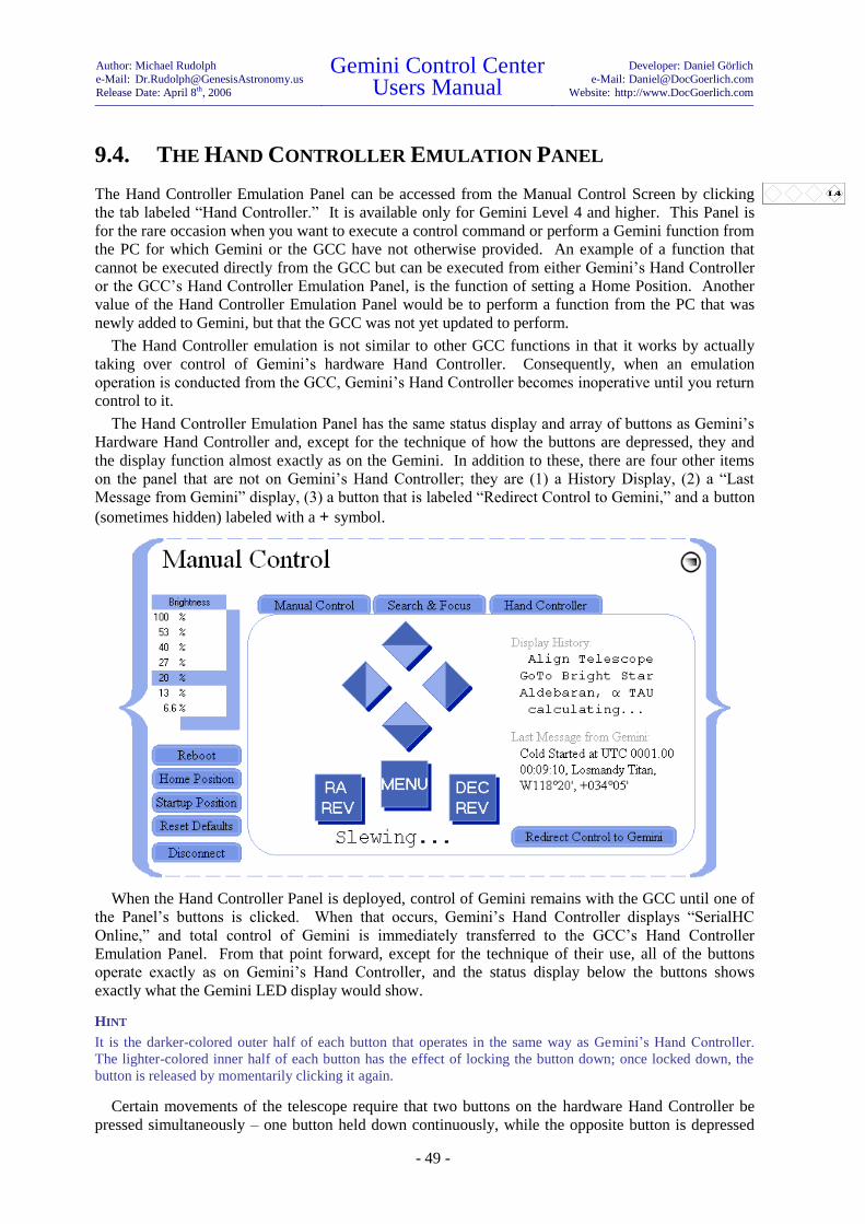
Author: Michael Rudolph
e-Mail: [email protected]
Release Date: April 8th, 2006
Gemini Control Center Users Manual
Developer: Daniel Görlich
e-Mail: [email protected]
Website: http://www.DocGoerlich.com
- 49 -
9.4. THE HAND CONTROLLER EMULATION PANEL
The Hand Controller Emulation Panel can be accessed from the Manual Control Screen by clicking
the tab labeled “Hand Controller.” It is available only for Gemini Level 4 and higher. This Panel is
for the rare occasion when you want to execute a control command or perform a Gemini function from
the PC for which Gemini or the GCC have not otherwise provided. An example of a function that
cannot be executed directly from the GCC but can be executed from either Gemini’s Hand Controller
or the GCC’s Hand Controller Emulation Panel, is the function of setting a Home Position. Another
value of the Hand Controller Emulation Panel would be to perform a function from the PC that was
newly added to Gemini, but that the GCC was not yet updated to perform.
The Hand Controller emulation is not similar to other GCC functions in that it works by actually
taking over control of Gemini’s hardware Hand Controller. Consequently, when an emulation
operation is conducted from the GCC, Gemini’s Hand Controller becomes inoperative until you return
control to it.
The Hand Controller Emulation Panel has the same status display and array of buttons as Gemini’s
Hardware Hand Controller and, except for the technique of how the buttons are depressed, they and
the display function almost exactly as on the Gemini. In addition to these, there are four other items
on the panel that are not on Gemini’s Hand Controller; they are (1) a History Display, (2) a “Last
Message from Gemini” display, (3) a button that is labeled “Redirect Control to Gemini,” and a button
(sometimes hidden) labeled with a + symbol.
When the Hand Controller Panel is deployed, control of Gemini remains with the GCC until one of
the Panel’s buttons is clicked. When that occurs, Gemini’s Hand Controller displays “SerialHC
Online,” and total control of Gemini is immediately transferred to the GCC’s Hand Controller
Emulation Panel. From that point forward, except for the technique of their use, all of the buttons
operate exactly as on Gemini’s Hand Controller, and the status display below the buttons shows
exactly what the Gemini LED display would show.
HINT
It is the darker-colored outer half of each button that operates in the same way as Gemini’s Hand Controller.
The lighter-colored inner half of each button has the effect of locking the button down; once locked down, the
button is released by momentarily clicking it again.
Certain movements of the telescope require that two buttons on the hardware Hand Controller be
pressed simultaneously – one button held down continuously, while the opposite button is depressed

Author: Michael Rudolph
e-Mail: [email protected]
Release Date: April 8th, 2006
Gemini Control Center Users Manual
Developer: Daniel Görlich
e-Mail: [email protected]
Website: http://www.DocGoerlich.com
- 50 -
for the duration of the movement. Since a PC mouse can only click one button at a time, a way has
been devised to accomplish this on the Hand Controller Emulation Panel by utilizing buttons that have
an inner and outer half.
To emulate holding down the right-hand directional button and then press the opposite (left) one,
for example, first click the lighter colored, inside half of the right button; the entire right button will
instantly turn white, a previously hidden button labeled with a + symbol will appear, and Gemini will
perform whatever function holding down the right Hand Controller button would normally perform.
Now to simulate pressing and holding the opposite (left) Hand Controller button, briefly click the
button labeled with the + symbol. The appropriate telescope movement will continue until the right-
hand directional button is released by clicking its outer half. This procedure can be performed to
simulate double-pressing any opposite pair of directional buttons.
Special procedures have been devised for selecting the objects of certain catalogs. When the SAO,
WDS, or GPN catalogs are selected, alphanumeric keys and East and West buttons appear for entering
the catalog object’s ID designation. Only those buttons that are valid for input at the cursor’s position
are highlighted and activated; keys that provide inadmissible characters are grayed out.
When the Messier M, NGC, IC, Sh2-, LDN or LBN catalogs are selected, an input field and two
buttons (“Info” and “Go-to”) appear. Use the PC keyboard to type in the desired object’s ID
designation (e.g. NGC 6246 or NGC 6246A). You can then immediately slew to the object by
clicking “Go-to,” or you can first display information about the object42
by clicking “Info.” Although
the “Go-to” button will disappear after clicking “Info,” you can subsequently slew to the designated
object by clicking the right RA directional button twice. There are no special instructions for selecting
and slewing to Solar System and Bright Star objects; you access them from the Hand Controller
Emulation Panel exactly as you would from Gemini’s Hand Controller.
HINT
It does not matter whether you enter upper or lower case letters for an object’s ID designation, however, catalog
name designations such as NGC or IC cannot be overwritten. Furthermore, the GCC knows the range of IDs
(numbers) that is admissible for each catalog, and will not let you visualize object “Info” or Go-to an alleged
object if the input ID is out of range (e.g. M125); it cannot, however, test whether a final letter in an ID is
admissible. If an input ID is within the permissible range of a catalog, the GCC will receive it, but cannot
determine if the ID actually represents a valid object; it will therefore rely on the Gemini to either accept it or
propose alternatives.
For your convenience, each time you perform an operation from the Hand Controller Emulation
Panel, Gemini’s last message and a several-line history of Gemini’s previous operations will be
displayed. When you are finished using the Hand Controller Emulation Panel and wish to resume
normal operations, just click the button labeled “Redirect Control to Gemini.” The panel will close,
42
See “Database Use” in Chapter 5 of the Gemini Users Manual.
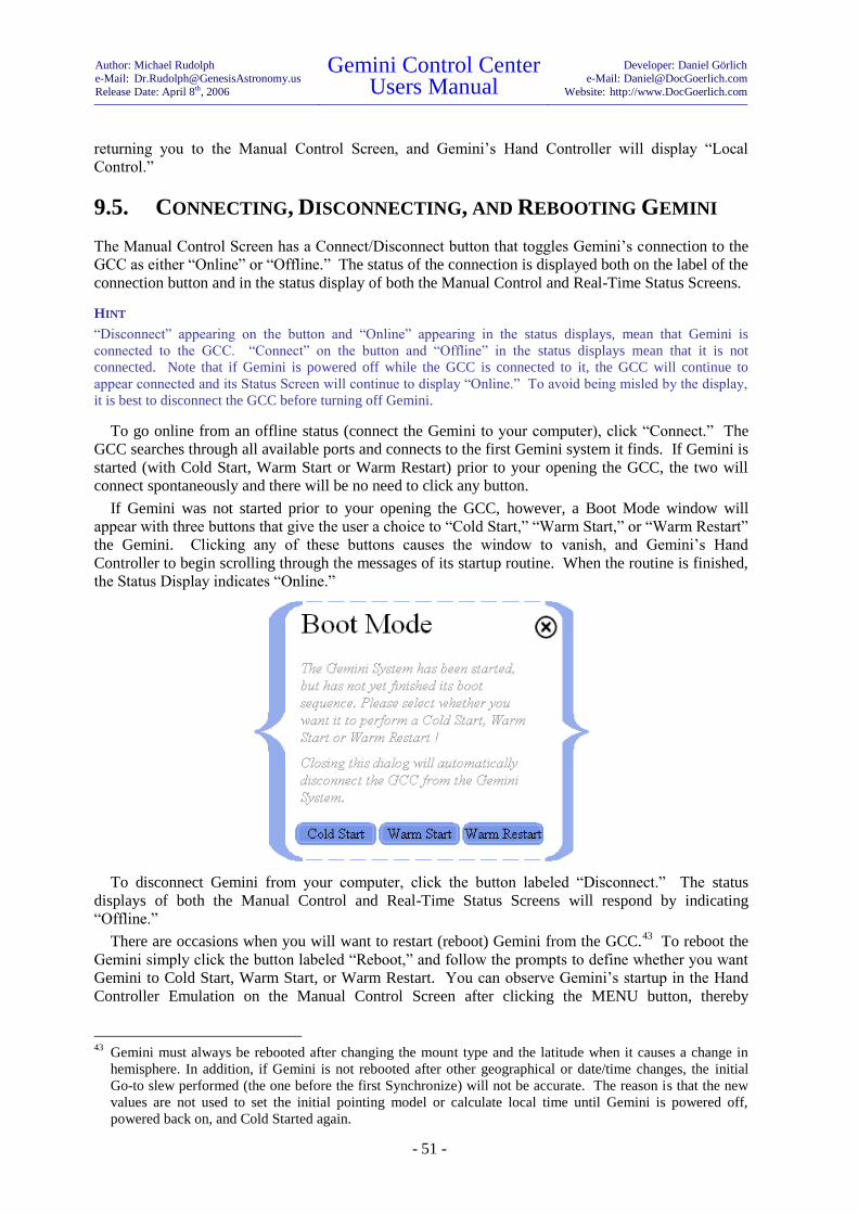
Author: Michael Rudolph
e-Mail: [email protected]
Release Date: April 8th, 2006
Gemini Control Center Users Manual
Developer: Daniel Görlich
e-Mail: [email protected]
Website: http://www.DocGoerlich.com
- 51 -
returning you to the Manual Control Screen, and Gemini’s Hand Controller will display “Local
Control.”
9.5. CONNECTING, DISCONNECTING, AND REBOOTING GEMINI
The Manual Control Screen has a Connect/Disconnect button that toggles Gemini’s connection to the
GCC as either “Online” or “Offline.” The status of the connection is displayed both on the label of the
connection button and in the status display of both the Manual Control and Real-Time Status Screens.
HINT
“Disconnect” appearing on the button and “Online” appearing in the status displays, mean that Gemini is
connected to the GCC. “Connect” on the button and “Offline” in the status displays mean that it is not
connected. Note that if Gemini is powered off while the GCC is connected to it, the GCC will continue to
appear connected and its Status Screen will continue to display “Online.” To avoid being misled by the display,
it is best to disconnect the GCC before turning off Gemini.
To go online from an offline status (connect the Gemini to your computer), click “Connect.” The
GCC searches through all available ports and connects to the first Gemini system it finds. If Gemini is
started (with Cold Start, Warm Start or Warm Restart) prior to your opening the GCC, the two will
connect spontaneously and there will be no need to click any button.
If Gemini was not started prior to your opening the GCC, however, a Boot Mode window will
appear with three buttons that give the user a choice to “Cold Start,” “Warm Start,” or “Warm Restart”
the Gemini. Clicking any of these buttons causes the window to vanish, and Gemini’s Hand
Controller to begin scrolling through the messages of its startup routine. When the routine is finished,
the Status Display indicates “Online.”
To disconnect Gemini from your computer, click the button labeled “Disconnect.” The status
displays of both the Manual Control and Real-Time Status Screens will respond by indicating
“Offline.”
There are occasions when you will want to restart (reboot) Gemini from the GCC.43
To reboot the
Gemini simply click the button labeled “Reboot,” and follow the prompts to define whether you want
Gemini to Cold Start, Warm Start, or Warm Restart. You can observe Gemini’s startup in the Hand
Controller Emulation on the Manual Control Screen after clicking the MENU button, thereby
43
Gemini must always be rebooted after changing the mount type and the latitude when it causes a change in
hemisphere. In addition, if Gemini is not rebooted after other geographical or date/time changes, the initial
Go-to slew performed (the one before the first Synchronize) will not be accurate. The reason is that the new
values are not used to set the initial pointing model or calculate local time until Gemini is powered off,
powered back on, and Cold Started again.

Author: Michael Rudolph
e-Mail: [email protected]
Release Date: April 8th, 2006
Gemini Control Center Users Manual
Developer: Daniel Görlich
e-Mail: [email protected]
Website: http://www.DocGoerlich.com
- 52 -
redirecting the message display to the GCC. You can speed up the startup sequence by holding the
right arrow button pressed while the initial startup message scrolls through.
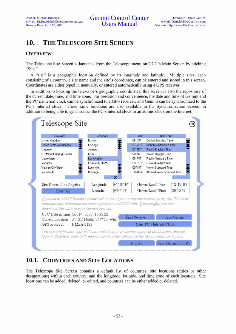
Author: Michael Rudolph
e-Mail: [email protected]
Release Date: April 8th, 2006
Gemini Control Center Users Manual
Developer: Daniel Görlich
e-Mail: [email protected]
Website: http://www.DocGoerlich.com
- 53 -
10. THE TELESCOPE SITE SCREEN
OVERVIEW
The Telescope Site Screen is launched from the Telescope menu on GCC’s Main Screen by clicking
“Site.”
A “site” is a geographic location defined by its longitude and latitude. Multiple sites, each
consisting of a country, a site name and the site’s coordinate, can be entered and stored in this screen.
Coordinates are either typed in manually, or entered automatically using a GPS receiver.
In addition to housing the telescope’s geographic coordinates, this screen is also the repository of
the current date, time, and time zone. For precision and convenience, the date and time of Gemini and
the PC’s internal clock can be synchronized to a GPS receiver, and Gemini can be synchronized to the
PC’s internal clock. These same functions are also available in the Synchronization Screen, in
addition to being able to synchronize the PC’s internal clock to an atomic clock on the Internet.
10.1. COUNTRIES AND SITE LOCATIONS
The Telescope Site Screen contains a default list of countries, site locations (cities or other
designations) within each country, and the longitude, latitude, and time zone of each location. Site
locations can be added, deleted, or edited, and countries can be either added or deleted.

Author: Michael Rudolph
e-Mail: [email protected]
Release Date: April 8th, 2006
Gemini Control Center Users Manual
Developer: Daniel Görlich
e-Mail: [email protected]
Website: http://www.DocGoerlich.com
- 54 -
10.1.1. ADDING A SITE LOCATION
To add a site location to a previously listed country, begin by selecting the country. Next, type a name
for the site in the box labeled “Site Name,” and select the site’s time zone from the Time Zone list on
the right side of the screen. The site name chosen can be anything – a city, a park, or just a personal
description like “Home.” Finally, enter the site’s longitude and latitude in the boxes provided, and
click “Save Site.” The site will appear in the Locations list whenever you select the site’s country.
To add a site location and a country that is not yet listed, first enter the site’s longitude, latitude, and
time zone. Next, type the site’s name in the “Site Name” box followed by a comma, a space, and the
country’s name (e.g. “St. Peter’s Basilica, Vatican”). Finally, click “Save Site.” The country, the site,
and the site’s parameters will be added and saved.
10.1.2. EDITING AND DELETING SITE LOCATIONS AND COUNTRIES
A saved site location can be edited by selecting it, changing any of its parameters (longitude, latitude,
or time zone, but not its name), and then clicking “Save Site.” To delete a site location, select it and
click the delete mark . A country is automatically deleted when its last site location is deleted.
HINT
Site locations and their related countries are saved as lines of simple text in the “Locations.gld” file of GCC’s
“Databases” subdirectory, from where they may be edited, deleted, or overwritten.
10.1.3. SETTING GEMINI’S GEOGRAPHIC COORDINATES AND TIME ZONE
MANUALLY
Gemini must be told the longitude, latitude, and time zone of the telescope’s location; this may be
done in one of two ways. You may either select a previously saved site location (in which case the
geographic coordinates and time zone of the site will be displayed) or, you can type the telescope’s
longitude and latitude into their respectively labeled boxes, and select the appropriate time zone from
the Time Zone list located on the right side of the screen. Either method will instantly transfer the
appropriate site parameters to the Gemini.
HINT
Gemini and the GCC only store a time zone’s numerical value – not its name. That is why all time zones with
the same value become highlighted when a site location is selected.
10.1.4. SETTING GEMINI’S DATE AND TIME MANUALLY
In order to point accurately, the Gemini must be told the correct time zone first, and then set to the
current date and time. To set Gemini’s date and time manually from the GCC, simply type the current
local date and time into the Telescope Site Screen’s boxes labeled “Gemini Local Date” and “Gemini
Local Time,” respectively.44
Date and time entries are instantly downloaded to the Gemini.
HINT
Setting Gemini’s time has no affect on the computer’s time or visa versa. The computer’s time can only be
manually set from the Windows Control Panel or the time display embedded in the PC’s System Tray.
44
When Gemini’s date and time are set from the GCC, it is “local” date and time – not UTC – that is entered.
That is not the case when one enters the date and time directly from Gemini’s Hand Controller.

Author: Michael Rudolph
e-Mail: [email protected]
Release Date: April 8th, 2006
Gemini Control Center Users Manual
Developer: Daniel Görlich
e-Mail: [email protected]
Website: http://www.DocGoerlich.com
- 55 -
10.1.5. SETTING GEMINI’S GEOGRAPHIC COORDINATES, DATE AND TIME
FROM A GPS RECEIVER
An alternative way to set the Gemini’s longitude, latitude and time is to download the information
from a GPS45
receiver.46
In order for the GCC to receive its data, several satellites must be visible to
the GPS receiver which, in turn must communicate to the GCC by either “NMEA 0183,” “Garmin
Textout,” or “RTCM SC-104” protocols at 4800 baud.
To accomplish this, connect a GPS receiver to any serial port on your computer,47
and click “Find
Receiver.” After a few seconds of delay, if the GPS receiver is receiving sufficient satellite data, the
UTC date and time, the telescope’s geographic coordinates, and the GPS receiver’s communication
protocol will be displayed at the bottom left of the screen;48
at this point, nothing will have yet been
downloaded to the Gemini.
Now, provided that the time zone has been properly set, clicking “Sync Gemini” will download the
displayed UTC date and time to the Gemini, and Gemini’s computed local date and time will promptly
be reflected in the boxes labeled “Gemini Local Date” and “Gemini Local Time” respectively.
Simultaneously, the displayed GPS geographic coordinates will be downloaded to the Gemini, and
instantly mirrored in the boxes labeled “Longitude” and “Latitude.”
If desired, the latitude, longitude and time zone set in this way can be given a site name and saved
for future retrieval.
10.1.6. SYNCHRONIZING THE COMPUTER TO GPS TIME
Synchronizing Gemini to the GPS receiver’s date and time does not automatically set the PC’s internal
clock. This may, however, be accomplished as a separate step, by first downloading the GPS
receiver’s data as described in the preceding section, and then clicking “Sync PC’s Internal Clock.”49
HINT
Until “Find Receiver” is clicked, there can be no link established between the GCC and a GPS receiver. When
“Find Receiver” is clicked, the GCC searches for a GPS receiver that may be connected to the PC and, if it finds
one, it tries to extract the GPS’ date, time, and geographic coordinates. If the GCC detects a GPS receiver but is
unable to extract its data, the GCC assumes that it does not know the receiver’s protocol, so it displays “Protocol:
unknown;” this is so even if there is a failure of the GPS receiver itself, and even if the GCC had previously
identified the receiver’s protocol as “Garmin Textout,” “NMEA 0183,” or “RTCM SC-104.”
The GCC only retains a link with the GPS receiver long enough to extract its date, time, and geographic data.
Once the data has been extracted, the link to the GPS receiver is broken, and the GCC calculates the offset
between the GPS’ and the PC’s date and time. The GCC then simulates, in memory, the time elapsing on the
GPS receiver’s clock, so that the GCC can keep track of the receiver clock’s time without remaining linked to it.
When the user clicks “Sync PC’s Internal Clock” or “Sync Gemini,” no link is established, but the calculated
(simulated) time is transferred to the PC’s clock or Gemini’s clock respectively (a small time delay may occur
since the GCC cannot set Gemini’s clock to the millisecond). The date/time, location, and protocol labels are
45
Global Positioning System
46 This procedure can be done from the Synchronization Screen as well.
47 In case your GPS receiver does not communicate with your PC via a serial (RS232) port (e.g. COM2), or via
a USB connection simulating a virtual serial port, please see the section of the Gemini Users Manual, entitled
“Connecting a GPS Receiver” for a description of how to wire your GPS receiver to your computer using a
standard serial connector.
48 As soon as the GCC has received sufficient data, it disconnects from the GPS receiver, thereby allowing it to
be unplugged with no adverse consequence. It then continues to count the seconds that have passed since the
last data retrieval.
49 Another way to automatically set the PC’s internal clock is by synchronizing to an SNTP server via the
Internet. This is described in the “Synchronization Screen” chapter.

Author: Michael Rudolph
e-Mail: [email protected]
Release Date: April 8th, 2006
Gemini Control Center Users Manual
Developer: Daniel Görlich
e-Mail: [email protected]
Website: http://www.DocGoerlich.com
- 56 -
then reset to “Unknown,” so that the user can again click “Find Receiver” to extract and recalculate the time
offset between the GCC’s and the GPS receiver’s clock.
10.1.7. SYNCHRONIZING THE COMPUTER TO AN INTERNET TIME SERVER
The GCC provides you with a convenient way to synchronize the date and time of your computer’s
internal clock to an SNTP Internet Server. To accomplish this, simply connect to the Internet and
click “Sync PC.” This same operation can be performed from the Synchronization Screen; for a full
description, see section 11.1 of this manual.
10.1.8. SYNCHRONIZING GEMINI’S DATE AND TIME FROM THE COMPUTER
If you know that your computer’s internal clock is accurately set because you previously synchronized
it to a standard source (e.g. a GPS receiver or an SNTP Internet Server), you can synchronize the
Gemini’s date and time from your computer by clicking “Sync Gemini from PC.” This same
operation can also be performed from the Synchronization Screen.
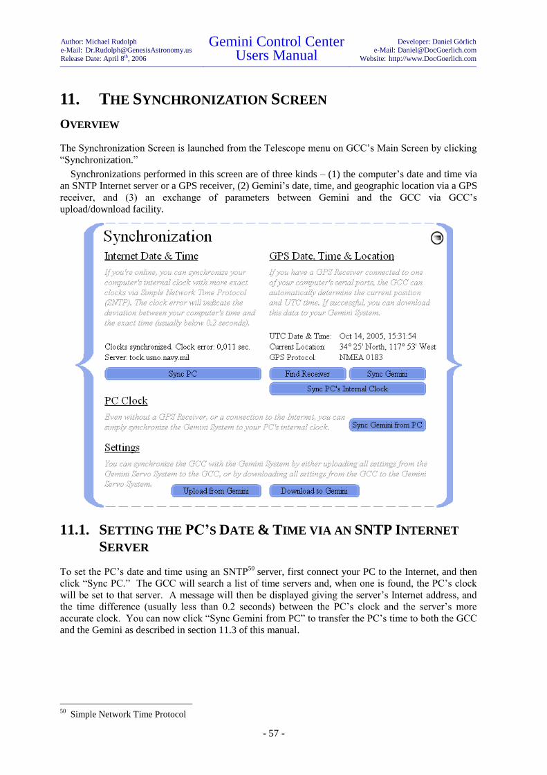
Author: Michael Rudolph
e-Mail: [email protected]
Release Date: April 8th, 2006
Gemini Control Center Users Manual
Developer: Daniel Görlich
e-Mail: [email protected]
Website: http://www.DocGoerlich.com
- 57 -
11. THE SYNCHRONIZATION SCREEN
OVERVIEW
The Synchronization Screen is launched from the Telescope menu on GCC’s Main Screen by clicking
“Synchronization.”
Synchronizations performed in this screen are of three kinds – (1) the computer’s date and time via
an SNTP Internet server or a GPS receiver, (2) Gemini’s date, time, and geographic location via a GPS
receiver, and (3) an exchange of parameters between Gemini and the GCC via GCC’s
upload/download facility.
11.1. SETTING THE PC’S DATE & TIME VIA AN SNTP INTERNET
SERVER
To set the PC’s date and time using an SNTP50
server, first connect your PC to the Internet, and then
click “Sync PC.” The GCC will search a list of time servers and, when one is found, the PC’s clock
will be set to that server. A message will then be displayed giving the server’s Internet address, and
the time difference (usually less than 0.2 seconds) between the PC’s clock and the server’s more
accurate clock. You can now click “Sync Gemini from PC” to transfer the PC’s time to both the GCC
and the Gemini as described in section 11.3 of this manual.
50
Simple Network Time Protocol

Author: Michael Rudolph
e-Mail: [email protected]
Release Date: April 8th, 2006
Gemini Control Center Users Manual
Developer: Daniel Görlich
e-Mail: [email protected]
Website: http://www.DocGoerlich.com
- 58 -
11.2. SETTING DATE, TIME AND LOCATION VIA A GPS RECEIVER
Setting both the PC’s and the Gemini’s date and time can also be accomplished by downloading them,
via a GPS receiver,51
from either this screen or from the Telescope Site Screen. Done in this way, you
get the bonus of downloading the longitude and latitude of the telescope’s position to Gemini via the
GCC as well. The GCC can connect to any GPS receiver connected to the PC’s serial port, provided
that it communicates by either “NMEA 0183,” “Garmin Textout,” or “RTCM SC-104” protocols at
4800 baud.52
To initiate the download, click “Find Receiver.”53
During a pause of several seconds, the message
“Searching…” will appear. If the GCC finds and connects to the GPS receiver, the UTC Date &
Time, the Current Location, and the GPS Protocol will be displayed.54
Then, clicking “Sync Gemini”
and “Sync PC’s Internal Clock,” in that order, will download the GPS receiver’s date, time, and
location to the Gemini, and will also set the PC’s internal clock.55
HINT
Until “Find Receiver” is clicked, there can be no link established between the GCC and a GPS receiver. When
“Find Receiver” is clicked, the GCC searches for a GPS receiver that may be connected to the PC and, if it finds
one, it tries to extract the GPS’ date, time, and geographic coordinates. If the GCC detects a GPS receiver but is
unable to extract its data, the GCC assumes that it does not know the receiver’s protocol, so it displays “Protocol:
unknown;” this is so even if there is a failure of the GPS receiver itself, and even if the GCC had previously
identified the receiver’s protocol as “Garmin Textout,” “NMEA 0183,” or “RTCM SC-104.”
The GCC only retains a link with the GPS receiver long enough to extract its date, time, and geographic data.
Once the data has been extracted, the link to the GPS receiver is broken, and the GCC calculates the offset
between the GPS’ and the PC’s date and time. The GCC then simulates, in memory, the time elapsing on the
GPS receiver’s clock, so that the GCC can keep track of the receiver clock’s time without remaining linked to it.
When the user clicks “Sync PC’s Internal Clock” or “Sync Gemini,” no link is established, but the calculated
(simulated) time is transferred to the PC’s clock or Gemini’s clock respectively (a small time delay may occur
since the GCC cannot set Gemini’s clock to the millisecond). The date/time, location, and protocol labels are
then reset to “Unknown,” so that the user can again click “Find Receiver” to extract and recalculate the time
offset between the GCC’s and the GPS receiver’s clock.
11.3. SYNCHRONIZING GEMINI FROM THE COMPUTER
If you know that your computer’s clock is accurately set because you previously synchronized it to a
standard source (e.g. a GPS receiver or an SNTP Internet Server), you can synchronize the Gemini
from your computer by clicking “Sync Gemini from PC.” This operation may also be performed from
the Telescope Site Screen.
11.4. UPLOADING AND DOWNLOADING SETTINGS
Generally, it will not be necessary to synchronize the GCC and the Gemini in separate operations.
This is because, upon their connecting, all of Gemini’s settings will normally upload to the GCC
51
Global Positioning System
52 See “Connecting a GPS Receiver” (Section 6.3) of the Gemini Users Manual for a description of how to wire
your GPS receiver to your computer using a standard serial connector. 53
The geographic time zone must have previously been set in the Telescope Site Screen.
54 As soon as the GCC has received sufficient data, it disconnects from the GPS receiver, thereby allowing it to
be unplugged with no adverse consequence. It then continues to count the seconds that have passed since the
last data retrieval. 55
It is more efficient to sync the Gemini before the PC because the GCC resets its simulation of the GPS
receiver's time once it has synchronized the PC's clock. If you want to sync the PC's clock first, you must
query the GPS receiver twice.

Author: Michael Rudolph
e-Mail: [email protected]
Release Date: April 8th, 2006
Gemini Control Center Users Manual
Developer: Daniel Görlich
e-Mail: [email protected]
Website: http://www.DocGoerlich.com
- 59 -
automatically. Then, when any parameter is changed in either of them, the change is mirrored in the
other.
That notwithstanding, there may be times (perhaps influenced by other control software running on
the PC) when a complete synchronization does not occur as expected. In those cases, you can force a
synchronization of all settable parameters by clicking either “Upload from Gemini” or “Download to
Gemini.” In the former case, the GCC receives its settings from Gemini; in the latter case, Gemini
receives them from the GCC.
HINT
If the GCC and Gemini are not connected and you wish to establish and store a set of parameters for download to
the Gemini once a connection has been made, you may do so by creating a profile in the Configuration Screen.
ANOTHER HINT
The GCC was designed to control the Gemini without using the Hand Controller. The more the Hand Controller
and the GCC are used concurrently, the more often it will be necessary to synchronize the Gemini and GCC. If
the Hand Controller is not used at all, you will probably never have to upload or download settings.

Author: Michael Rudolph
e-Mail: [email protected]
Release Date: April 8th, 2006
Gemini Control Center Users Manual
Developer: Daniel Görlich
e-Mail: [email protected]
Website: http://www.DocGoerlich.com
- 60 -
12. THE PRECESSION CALCULATOR SCREEN
OVERVIEW
The Precession Calculator Screen is launched from the Tools menu on GCC’s Main Screen by
clicking “Precession.”
Precession is caused by a slow circular movement of the rotational axis of the Earth that must be
accounted for when attempting to accurately point a telescope toward a celestial object. While a full
discussion of precession is beyond the scope of this manual, the Right Ascension and Declination data
published in astronomical catalogs (of which several are resident in the Gemini and the GCC) must be
adjusted for its affect, or Gemini will not point to the apparent position of the target.
The International Astronomical Union (IAA) defines so-called “Standard Epochs” for astronomical
catalogs. The current standard epoch is J2000.0, meaning that coordinates in newer catalogs are now
corrected to January 1st, 2000 at 12:00 o’clock UTC.
Gemini usually expects coordinates to be in the Standard Epoch J2000.0.56
The permanently stored
catalogs on-board Gemini are therefore based on J2000.0, and User Catalog items that are downloaded
have to refer to this equinox also. The GCC's Precession Calculator Screen helps to convert
coordinates based on other equinoxes to those of J2000.0.
12.1. ENTERING COORDINATES AND EPOCH DATE
Coordinates are entered in the Precession Calculator Screen in one of two ways. They are either typed
into its Object Coordinate Box, or are copied in from other object-transferable screens.57
This is done
by selecting the object in the other screen while the Precession Calculator Screen is open.
The epoch date is selected from the “Epoch Date” list. J2000.0, B1950 and J1900 are the epochs of
their respective years. “Today’s Equinox” refers to noon of the current date (the date to which the PC
is set), and “Base Date Equinox” refers to noon of the date entered in the box labeled “Base Date.”
56
Exceptions are the Manual Control Screen where coordinates can be input in “Today’s Equinox,” and the
Bookmarks Panel of the Catalogs Screen where coordinates can be input in any equinox.
57 The Catalogs Screen, Observation Schedules Screen, Manual Control Screen, and the Near Objects Screen.

Author: Michael Rudolph
e-Mail: [email protected]
Release Date: April 8th, 2006
Gemini Control Center Users Manual
Developer: Daniel Görlich
e-Mail: [email protected]
Website: http://www.DocGoerlich.com
- 61 -
12.2. CALCULATING AND TRANSFERRING THE RESULTS
The resulting epoch date is selected from the “Results” list. As with the “Input Epoch Date,”
“Today’s Equinox” refers to noon of the current date, and “Base Date Equinox” refers to noon of the
date entered in the box labeled “Base Date.” The resulting (corrected) Right Ascension and
Declination are displayed simultaneously for all the epoch dates listed. Any one of them can now be
copied to other object-transferable screens by selecting it and clicking “Transfer Selected Result”
while the receiving screen is open.

Author: Michael Rudolph
e-Mail: [email protected]
Release Date: April 8th, 2006
Gemini Control Center Users Manual
Developer: Daniel Görlich
e-Mail: [email protected]
Website: http://www.DocGoerlich.com
- 62 -
13. THE COLOR THEMES SCREEN
OVERVIEW
The Themes Screen is launched from the Tools menu on GCC’s Main Screen by clicking “Color
Themes.”
In addition to the two standard themes, the Daylight and Night Vision themes, this screen lets you
create a virtually unlimited number of custom themes, and load previously saved ones.
HINT
Each theme is saved as a separate file in the GCC’s “Databases” folder with a “.gcs” extension. Theme files can
be added and deleted there, and can be overwritten by updated files. This allows the import of themes created by
other GCC users.
13.1. DEFINING CUSTOM THEMES
A color theme is defined by coloring the 33 elements listed on the left side of the Themes Screen (the
“Colorable Elements List”). Below this list are a color map, a selection of pre-defined basic colors,
and three edit boxes that let you select one specific color out of 16 million possibilities. This color is
defined by the RGB model, which constructs every color by combining saturation levels of the three
primary colors, red, green and blue. The admissible range for each saturation level is 0 to 255.58
When you move the mouse over the color map or over one of the basic colors fields, the selected
color will be shown in the upper-left of the two boxes to the right of the color map. Simultaneously,
the color’s red, green, and blue saturation levels are displayed in their respective edit boxes. This
helps you find and select a specific color; when you have found it, simply click on it and the color will
be selected.
If you want to be even more specific, you can enter a color’s red, green, and blue saturation levels
directly into their respective edit boxes, and press <RETURN>.
When you select a color, it is stored in the lower-right of the two boxes to the right of the color map.
Then, if an item is selected in the Colorable Elements List, the selected color is automatically assigned
58
A complete description of the RGB color model is beyond the scope of this manual. You can find detailed
information about “RGB colors” on the Internet.
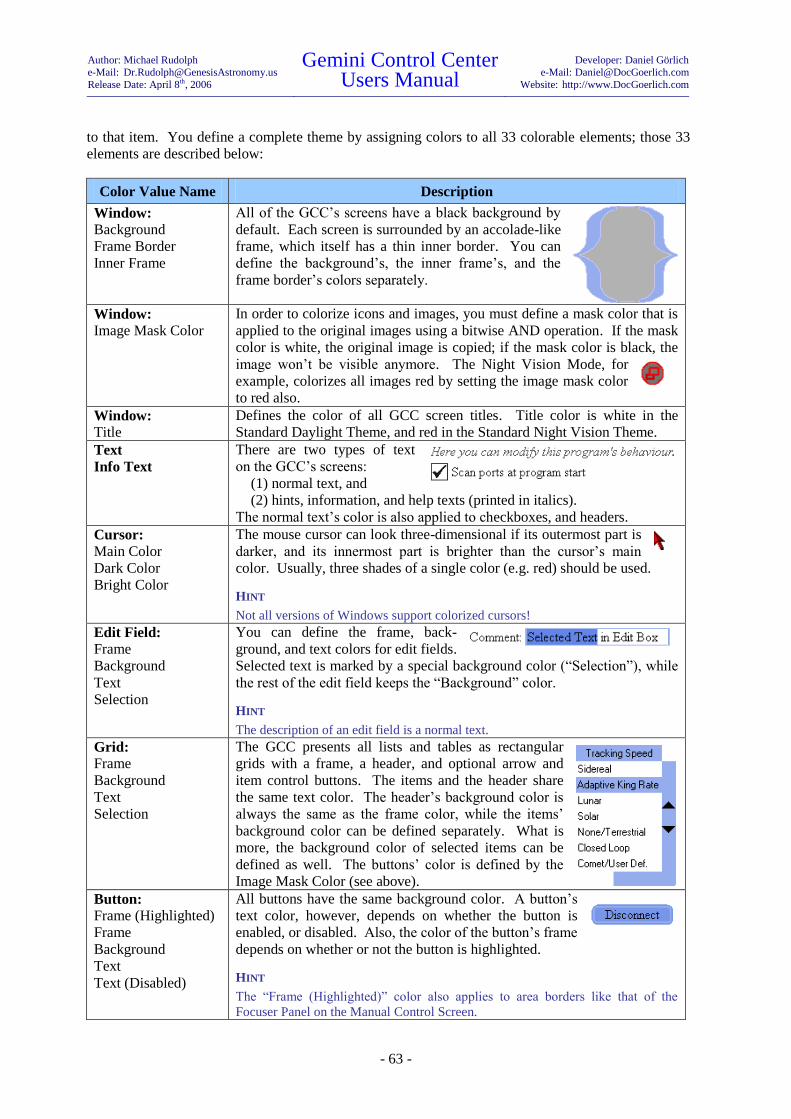
Author: Michael Rudolph
e-Mail: [email protected]
Release Date: April 8th, 2006
Gemini Control Center Users Manual
Developer: Daniel Görlich
e-Mail: [email protected]
Website: http://www.DocGoerlich.com
- 63 -
to that item. You define a complete theme by assigning colors to all 33 colorable elements; those 33
elements are described below:
Color Value Name Description
Window:
Background
Frame Border
Inner Frame
All of the GCC’s screens have a black background by
default. Each screen is surrounded by an accolade-like
frame, which itself has a thin inner border. You can
define the background’s, the inner frame’s, and the
frame border’s colors separately.
Window:
Image Mask Color
In order to colorize icons and images, you must define a mask color that is
applied to the original images using a bitwise AND operation. If the mask
color is white, the original image is copied; if the mask color is black, the
image won’t be visible anymore. The Night Vision Mode, for
example, colorizes all images red by setting the image mask color
to red also.
Window:
Title
Defines the color of all GCC screen titles. Title color is white in the
Standard Daylight Theme, and red in the Standard Night Vision Theme.
Text
Info Text
There are two types of text
on the GCC’s screens:
(1) normal text, and
(2) hints, information, and help texts (printed in italics).
The normal text’s color is also applied to checkboxes, and headers.
Cursor:
Main Color
Dark Color
Bright Color
The mouse cursor can look three-dimensional if its outermost part is
darker, and its innermost part is brighter than the cursor’s main
color. Usually, three shades of a single color (e.g. red) should be used.
HINT
Not all versions of Windows support colorized cursors!
Edit Field:
Frame
Background
Text
Selection
You can define the frame, back-
ground, and text colors for edit fields.
Selected text is marked by a special background color (“Selection”), while
the rest of the edit field keeps the “Background” color.
HINT
The description of an edit field is a normal text.
Grid:
Frame
Background
Text
Selection
The GCC presents all lists and tables as rectangular
grids with a frame, a header, and optional arrow and
item control buttons. The items and the header share
the same text color. The header’s background color is
always the same as the frame color, while the items’
background color can be defined separately. What is
more, the background color of selected items can be
defined as well. The buttons’ color is defined by the
Image Mask Color (see above).
Button:
Frame (Highlighted)
Frame
Background
Text
Text (Disabled)
All buttons have the same background color. A button’s
text color, however, depends on whether the button is
enabled, or disabled. Also, the color of the button’s frame
depends on whether or not the button is highlighted.
HINT
The “Frame (Highlighted)” color also applies to area borders like that of the
Focuser Panel on the Manual Control Screen.
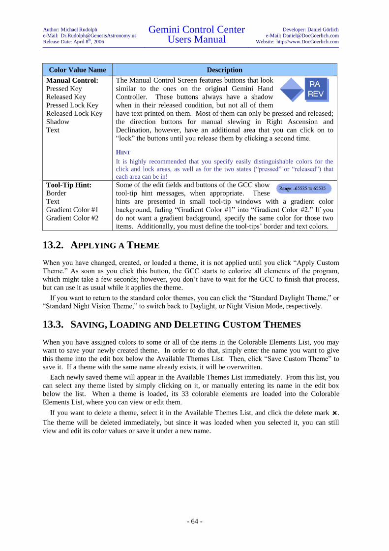
Author: Michael Rudolph
e-Mail: [email protected]
Release Date: April 8th, 2006
Gemini Control Center Users Manual
Developer: Daniel Görlich
e-Mail: [email protected]
Website: http://www.DocGoerlich.com
- 64 -
Color Value Name Description
Manual Control:
Pressed Key
Released Key
Pressed Lock Key
Released Lock Key
Shadow
Text
The Manual Control Screen features buttons that look
similar to the ones on the original Gemini Hand
Controller. These buttons always have a shadow
when in their released condition, but not all of them
have text printed on them. Most of them can only be pressed and released;
the direction buttons for manual slewing in Right Ascension and
Declination, however, have an additional area that you can click on to
“lock” the buttons until you release them by clicking a second time.
HINT
It is highly recommended that you specify easily distinguishable colors for the
click and lock areas, as well as for the two states (“pressed” or “released”) that
each area can be in!
Tool-Tip Hint:
Border
Text
Gradient Color #1
Gradient Color #2
Some of the edit fields and buttons of the GCC show
tool-tip hint messages, when appropriate. These
hints are presented in small tool-tip windows with a gradient color
background, fading “Gradient Color #1” into “Gradient Color #2.” If you
do not want a gradient background, specify the same color for those two
items. Additionally, you must define the tool-tips’ border and text colors.
13.2. APPLYING A THEME
When you have changed, created, or loaded a theme, it is not applied until you click “Apply Custom
Theme.” As soon as you click this button, the GCC starts to colorize all elements of the program,
which might take a few seconds; however, you don’t have to wait for the GCC to finish that process,
but can use it as usual while it applies the theme.
If you want to return to the standard color themes, you can click the “Standard Daylight Theme,” or
“Standard Night Vision Theme,” to switch back to Daylight, or Night Vision Mode, respectively.
13.3. SAVING, LOADING AND DELETING CUSTOM THEMES
When you have assigned colors to some or all of the items in the Colorable Elements List, you may
want to save your newly created theme. In order to do that, simply enter the name you want to give
this theme into the edit box below the Available Themes List. Then, click “Save Custom Theme” to
save it. If a theme with the same name already exists, it will be overwritten.
Each newly saved theme will appear in the Available Themes List immediately. From this list, you
can select any theme listed by simply clicking on it, or manually entering its name in the edit box
below the list. When a theme is loaded, its 33 colorable elements are loaded into the Colorable
Elements List, where you can view or edit them.
If you want to delete a theme, select it in the Available Themes List, and click the delete mark .
The theme will be deleted immediately, but since it was loaded when you selected it, you can still
view and edit its color values or save it under a new name.
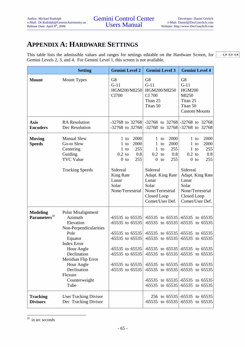
Author: Michael Rudolph
e-Mail: [email protected]
Release Date: April 8th, 2006
Gemini Control Center Users Manual
Developer: Daniel Görlich
e-Mail: [email protected]
Website: http://www.DocGoerlich.com
- 65 -
APPENDIX A: HARDWARE SETTINGS
This table lists the admissible values and ranges for settings editable on the Hardware Screen, for
Gemini Levels 2, 3, and 4. For Gemini Level 1, this screen is not available.
Setting Gemini Level 2 Gemini Level 3 Gemini Level 4
Mount Mount Types G8 G8 G8
G-11 G-11 G-11
HGM200/MI250 HGM200/MI250 HGM200
CI700 CI 700 MI250
Titan 25 Titan 25
Titan 50 Titan 50
Custom Mounts
Axis RA Resolution -32768 to 32768 -32768 to 32768 -32768 to 32768
Encoders Dec Resolution -32768 to 32768 -32768 to 32768 -32768 to 32768
Moving Manual Slew 1 to 2000 1 to 2000 1 to 2000
Speeds Go-to Slew 1 to 2000 1 to 2000 1 to 2000
Centering 1 to 255 1 to 255 1 to 255
Guiding 0.2 to 0.8 0.2 to 0.8 0.2 to 0.8
TVC Value 0 to 255 0 to 255 0 to 255
Tracking Speeds Sidereal Sidereal Sidereal
King Rate Adapt. King Rate Adapt. King Rate
Lunar Lunar Lunar
Solar Solar Solar
None/Terrestrial None/Terrestrial None/Terrestrial
Closed Loop Closed Loop
Comet/User Def. Comet/User Def.
Modeling Polar Misalignment
Parameters59
Azimuth -65535 to 65535 -65535 to 65535 -65535 to 65535
Elevation -65535 to 65535 -65535 to 65535 -65535 to 65535
Non-Perpendicularities
Pole -65535 to 65535 -65535 to 65535 -65535 to 65535
Equator -65535 to 65535 -65535 to 65535 -65535 to 65535
Index Error
Hour Angle -65535 to 65535 -65535 to 65535 -65535 to 65535
Declination -65535 to 65535 -65535 to 65535 -65535 to 65535
Meridian Flip Error
Hour Angle -65535 to 65535 -65535 to 65535 -65535 to 65535
Declination -65535 to 65535 -65535 to 65535 -65535 to 65535
Flexure
Counterweight -65535 to 65535 -65535 to 65535
Tube -65535 to 65535 -65535 to 65535
Tracking User Tracking Divisor 256 to 65535 -65535 to 65535
Divisors
Dec Tracking Divisor -65535 to 65535 -65535 to 65535
59
in arc seconds

Author: Michael Rudolph
e-Mail: [email protected]
Release Date: April 8th, 2006
Gemini Control Center Users Manual
Developer: Daniel Görlich
e-Mail: [email protected]
Website: http://www.DocGoerlich.com
- 66 -
APPENDIX B: EXAMPLE EXERCISES
This Appendix presents a few common procedures for controlling the Gemini Astronomical
Positioning System (Gemini) with the Gemini Control Center (GCC). It is not intended as a
comprehensive tutorial, so it is selective and does not, therefore, illustrate many of the GCC’s
capabilities.
The examples that follow assume:
A telescope and Losmandy G-11 Mount, with Gemini Level 4.
Gemini is connected to PC via an RS-232 serial cable.
GCC is installed on PC, launched, and connected to Gemini.
Location is New York City (Long. +74º 00′ and Lat. +40º 42′).
Time zone is Eastern Standard Time (GMT -05).
Date and time of PC’s internal clock have been previously set.
Mount is polar aligned.
Gemini has been powered on in the standard CWD Startup Position (counterweight shaft
down and telescope pointing North), and Cold Started.
EXERCISE A: SETTING INITIAL PARAMETERS MANUALLY
There are ways to set Gemini’s parameters other than by manual input (e.g. via a GPS or a previously
saved Session Profile). In this exercise, however, we will manually set the parameters most often
needed after a Cold Start; these are moving speeds, Hand Controller mode, encoder usage, tracking
speed, geographic location, time zone, and local date and time.
1. Launch the GCC (Gemini has already been Cold Started). If the option “Scan ports at program
start” on the Configuration Screen is checked, the GCC will connect to Gemini spontaneously.
Otherwise, click the “Connect” button on the Main Screen.
2. Wait for about two seconds after connection, until the GCC has retrieved all current settings from
Gemini. You can observe this process by watching the Real-Time Status Screen as it fills with
values, or by opening (for example) the Hardware Screen and seeing how its settings change.
3. Deploy the Hardware Screen from the Main Screen and select or type in the following
parameters:
a) Manual Slew: 800
b) Go-to Slew: 800
c) Centering: 20
d) Guiding: 0.2
e) Hand Controller: Visual Mode
f) Encoder Usage: Ignore Encoders
g) Tracking Speed: None/Terrestrial
4. Deploy the Telescope Site Screen from the Main Screen and select or type in the following
parameters:
a) Countries: United States of America
b) Location: New York (this will enter Long. +074º 00', Lat. +40º 42')
c) Time Zone: -05 EST
d) Gemini Local Date: mm-dd-yy
e) Gemini Local Time: hh:mm:ss

Author: Michael Rudolph
e-Mail: [email protected]
Release Date: April 8th, 2006
Gemini Control Center Users Manual
Developer: Daniel Görlich
e-Mail: [email protected]
Website: http://www.DocGoerlich.com
- 67 -
HINT
Alternatively, clicking “Sync Gemini from PC” in the Site Screen or the equivalent button in the
Synchronization Screen will set both the date and the time from the PC’s internal clock; this will not, however,
automatically set the country and site location!
5. Click <RETURN> or close the screen.
EXERCISE B: SAVING SETTINGS IN A SESSION PROFILE
In this exercise, we will collect all of Gemini’s current settings and save all but the Mount Type in a
named Session Profile (calendar date and time are never saved in Session Profiles).
1. With the GCC and Gemini connected, deploy the Configuration Screen from the Main Screen
and then click “Collect Current Settings.” This will copy all current settings into temporary
memory.
2. Highlight “Mount Type” and delete it by clicking .
3. Type “My Profile” in the Name input box and click “Save Profile.”
“My Profile” will appear in the Available Profiles list. This profile contains all of the originally
collected settings except “Mount Type.”
EXERCISE C: RETRIEVING A SAVED SESSION PROFILE
In this exercise, we will first change some of the Gemini’s settings, and then restore them by loading
and applying the previously saved Session Profile named “My Profile.”
1. With the GCC and Gemini connected, deploy the Hardware Screen from the Main Screen and
change the following settings by selecting:
a. Hand Controller: All Speeds
b. Tracking Speed: Lunar
2. Deploy the Telescope Site Screen from the Main Screen and change the geographic coordinates
to:
a. Longitude: +075º 30'
b. Latitude: +39º 10'
The settings in paragraphs 1 and 2 have been changed merely to illustrate how the original settings
will return when the previously saved Session Profile is retrieved.
3. Deploy the Configuration Screen from the Main Screen.
4. Select “My Profile” from the Available Profiles list.
5. Click “Apply Listed Settings.”
You will discover, upon inspecting the Hardware and Telescope Site Screens, that the original
settings for Hand Controller, Tracking Speed, and geographic coordinates have been restored.
EXERCISE D: REBOOTING GEMINI FROM CWD STARTUP POSITION
In this exercise, you will return the telescope to its CWD (counterweight down) Startup Park Position
and reboot the Gemini from the GCC. This is necessary if you make certain changes to Gemini’s
settings following a Cold Start;60
refer to the Gemini Users Manual for further details on this subject.
60
Gemini must always be rebooted after changing the mount type and the latitude when it causes a change in
hemisphere. In addition, if Gemini is not rebooted after other geographical or date/time changes, the initial
Go-to slew performed (the one before the first Synchronize) will not be accurate. The reason is that the new
values are not used to set the initial pointing model or calculate local time until Gemini is powered off,
powered back on, and Cold Started again.
Author: Michael Rudolph
e-Mail: [email protected]
Release Date: April 8th, 2006
Gemini Control Center Users Manual
Developer: Daniel Görlich
e-Mail: [email protected]
Website: http://www.DocGoerlich.com
- 68 -
1. Deploy the Manual Control Screen from the Main Screen and click “Startup Position.” The
telescope begins to slew and returns to its CWD Startup Park Position.
2. Now, still in the Manual Control Screen, click “Reboot.”
HINT
You can observe Gemini’s startup in the Hand Controller emulation on the Manual Control Screen after clicking
the MENU button and thereby redirecting the message display to the GCC. You can speed up the startup
sequence by holding the right arrow button pressed while the initial startup message scrolls through.
3. After allowing the Gemini sufficient time to progress through its startup routine, a Boot Mode
Screen will appear that offers a choice of three start modes. Click “Cold Start” on the Boot Mode
Screen and allow the Gemini time to finish its startup routine. You are now ready to do your first
star alignment.
HINT
In case that the GCC does not display the Boot Mode Screen, click the “Disconnect,” and subsequently the
“Connect” button to re-initialize the connection between the GCC and the Gemini. Also, if you close the Boot
Mode Screen without choosing a startup routine, the GCC will automatically disconnect from the Gemini, and
you will have to re-connect it manually.
EXERCISE E: PERFORMING A TWO STAR ALIGNMENT, CREATING
A CUSTOM CATALOG, AND DETERMINING A STAR’S
EQUINOX OF THE DATE COORDINATES
In this exercise, you will select a first alignment star from the GCC’s Bright Star List, add the star to a
Custom Catalog, and then slew to and “Synchronize” on the star as a first star alignment. You will
then select a second alignment star from the GCC’s Bright Star List, add that star to the Custom
Catalog, and save the catalog under a unique name. You will then slew to the second star and perform
an “Additional Align” on it as a second star alignment. You will then transfer the second star’s
J2000.0 coordinates to the Precession Calculator from where you will determine its coordinates
precessed to the equinox of the current date.
1. With the GCC and Gemini connected, deploy the Hardware Screen from the Main Screen and
select Tracking Speed: “Sidereal” (remember, it was previously set to None/Terrestrial).
2. With the GCC and Gemini connected, deploy the Catalogs Screen from the Main Screen; the
Standard Catalogs Panel will open by default. Select the Bright Star List and deselect all other
catalogs that may already be selected. A total of 168 stellar objects will be loaded into the GCC
and appear in an alphabetized Object List.
HINT
Any number of Standard Catalogs can be loaded into the GCC simultaneously, numbering a total of 39,997
objects.
3. Select a star from the Object List – one that is suitable for a first star alignment from your
geographic location; if it is struck out on the list, it is not currently above the horizon. Notice that
the star’s Epoch J2000.0 coordinates appear to the right of the star’s name.
4. Switch to the Custom Catalogs Panel by clicking the tab labeled “Custom Catalogs.” The star
you selected in the Standard Catalogs Panel appears in the Object Input Box along with its
J2000.0 coordinates. Erase all items currently in the Object List by selecting them (by mouse-
drag or Shift-click) and then clicking . Clicking “Add” now copies the star and its coordinates
to the Object List.
5. Now click “Go-to;” the Additional Align and Synchronize buttons will become highlighted, and
the telescope will slew toward the star. If your polar alignment and Startup Position were
accurate, the telescope will come to rest so that the star will be visible in the telescope’s field of
Author: Michael Rudolph
e-Mail: [email protected]
Release Date: April 8th, 2006
Gemini Control Center Users Manual
Developer: Daniel Görlich
e-Mail: [email protected]
Website: http://www.DocGoerlich.com
- 69 -
view. Center the star in the telescope’s eyepiece and click “Synchronize.” You have just done a
first star alignment.
HINT
The star can be centered either from the GCC’s Manual Control Screen or using the Gemini’s Hand Controller.
6. Return to the Standard Catalogs Panel and select a second star from the Bright Star List. Switch
to the Custom Catalogs Panel once again, and observe that the second star you just selected has
now replaced the first star in the Object Input Box. Click “Add” to add the star and its
coordinates to the Object List.
7. Enter “My Custom Catalog” in the Catalog Name Box and click “Save Catalog.” A new Custom
Catalog named “My Custom Catalog” (containing the two selected stars) appears in the Catalog
List.
8. Now with the second star still in the Object Input Box, click “Go-to;” as before, the Additional
Align and Synchronize buttons will become highlighted, and the telescope will slew toward the
star. When the telescope comes to rest, center the star in the telescope’s eyepiece and click
“Additional Align.” You have now performed a second star alignment.
9. To determine the second star’s equinox of the current date, leave the Custom Catalogs Panel open
and deploy the Precession Calculator Screen from the Main Screen by clicking “Precession.”
When the Precession Calculator Screen opens, re-select the star in the Custom Catalogs Panel
and notice that the star’s J2000.0 coordinates are copied to the Precession Calculator Screen’s
Coordinate Input Box. J2000.0 will be selected as the input epoch date, and the Base Date field
will display the current local date. When you look over at the “Results” side, you will find the
star’s coordinates calculated to several equinoxes, including “Today’s Equinox,” where the star’s
coordinates are precessed to the equinox of the current date.
EXERCISE F: USING THE HAND CONTROLLER EMULATION
Wherever possible, control of the Gemini should be accomplished from the various GCC controls. A
Hand Controller Emulation Panel has, however, been provided for special situations in which the
GCC’s controls are inadequate. In this exercise, you will use the GCC’s Hand Controller Emulator
(HC Emulator) to first activate and then deactivate Gemini’s Alarm/Buzzer.
1. With the GCC connected to the Gemini, open the Manual Control Screen and click on the “Hand
Controller” tab. Since the Gemini’s Hand Controller display has not yet been redirected to the
HC Emulator, the “Redirect Control to Gemini” button of the Emulator is grayed out.
2. Briefly click the HC Emulator MENU button. The “Redirect Control to Gemini” button becomes
highlighted, and Gemini’s Emulator response (e.g. “M E N U” or “Sidereal Mode”) appears in
the display below the MENU button; simultaneously, Gemini’s Hand Controller LED displays
“Serial HC Online.” Since we want Gemini’s HC Emulator response to display “M E N U,” if it
does not, click the MENU button again.
HINT
If you hold down the mouse button too long while clicking on the HC Emulator’s MENU button, Gemini will
begin to scroll through its Shortcut Menus. If this happens, get out of the loop by clicking the MENU button
when “Exit w/o Change” appears on the display.
3. Click either the Up or Down button of the HC Emulator until Gemini’s Emulator response
displays “Setup;” click the Emulator’s Right button to enter Gemini’s Setup menu.
4. Click either the Up or Down button of the HC Emulator until Gemini’s Emulator response
displays “Alarm/Buzzer.”
5. Click the Right button of the HC Emulator; assuming that the Alarm/Buzzer was not previously
activated, this will cause Gemini’s Emulator response to display “Activate Alarm.”

Author: Michael Rudolph
e-Mail: [email protected]
Release Date: April 8th, 2006
Gemini Control Center Users Manual
Developer: Daniel Görlich
e-Mail: [email protected]
Website: http://www.DocGoerlich.com
- 70 -
6. Click the Right button of the HC Emulator again; Gemini’s Emulator response will display
“Alarm is On.” Congratulations. You have just succeeded in turning Gemini’s Alarm/Buzzer
on, so you will now proceed to turn it back off.
7. Click the HC Emulator’s MENU button until Gemini’s Emulator response displays “M E N U.”
Now repeat the previous steps 2 through 4, causing Gemini’s Emulator response to display
“Alarm/Buzzer.”
8. Click the HC Emulator’s Right button once again; Gemini’s Emulator response displays
“Deactivate Alarm.” Click the Right button again, and Gemini’s Emulator response displays
“Alarm is Off.” Congratulations again. You have succeeded in turning Gemini’s Alarm/Buzzer
back off.
7. To leave the HC Emulator, click “Redirect Control to Gemini;” this button will gray out,
Gemini’s LED will momentarily display “Local Control,” and the GCC’s Manual Control Panel
will be brought to the front of the Windows display.
HINT
At the time you direct control of the Gemini to the GCC’s HC Emulator, any menu, slewing mode or edit mode
could be active. You should therefore always activate the emulation using the Emulator’s MENU button
because, using a direction button to do so might change a setting or perform an unwanted operation.
ANOTHER HINT
If you change any settings using the HC Emulator, you should, as soon as possible thereafter, use the GCC
Synchronization Screen to retrieve all of Gemini’s settings. This should always be done after returning control
back to Gemini and before every use of a GCC screen to change a setting or perform an operation.
EXERCISE G: CREATING AN OBSERVATION DIARY AND A LOCAL
LOG FROM AN UPLOADED GEMINI LOG
In this exercise, you will create a local GCC Log and an Observation Diary from an uploaded Gemini
Log.
1. With the GCC connected to Gemini, deploy the Observation Logs Screen from the Main Screen
by clicking on “Logs & Diaries.”
2. If there are entries displayed in the list in the lower half of the screen, click the button labeled
“Clear Local Log” to empty it. (If you don’t, new entries will be appended to the ones that are
already contained in the list.)
3. In the Observation Logs Screen, click “Upload Gemini’s Log,” and Gemini’s entire stored log
will populate the lower part of the screen.
4. Type “My Local Log” into the Name Input Box and click “Save Local Log.” The name of the
log you just created has been saved, and its name appears under the caption “Saved Log Files.”
A Local Log File can be visualized at any time by selecting it but, in order to edit or print it out, it
has to first be converted to an Observation Diary.
HINT
In a real session, you might now want to clear Gemini’s log. You can do so by clicking “Clear Gemini’s Log,”
but you shouldn’t do that now!
5. To create an Observation Diary of “My Local Log,” first select it, and then click “Create
Observation Diary.” An Observation Diary Screen will open that will be populated with the data
contained in “My Local Log.”
6. Logged data in the Observation Diary can be edited, rearranged, deleted, commented upon, and
exported to a text file on your PC. To illustrate some of this capability, select the first line of the
log and click ; the line you selected has been deleted. Now click “Rebuild Diary,” and the line
that you deleted reappears.
Author: Michael Rudolph
e-Mail: [email protected]
Release Date: April 8th, 2006
Gemini Control Center Users Manual
Developer: Daniel Görlich
e-Mail: [email protected]
Website: http://www.DocGoerlich.com
- 71 -
7. Type “This is a test comment” in the Comment input box. Now select the second line of the log
and click “Set Comment.” The comment you just typed appears in the Comment column in the
second line of the log.
8. If you do not have a “C:\Temp” directory on your PC, create one now. Type the file name and
path “C:\Temp\My Observation Diary.txt” in the File Name input box and click “Export Diary.”
The entire diary, along with any edited changes you have made, will be exported to the C:\Temp
directory as a text file named “My Observation Diary.txt.” From there, you can edit it further,
and print it out using any text editor.
EXERCISE H: RECORDING THE POSITION OF CELESTIAL OBJECTS
In this exercise, you will “unexpectedly” come across a fictitious unknown celestial object whose
position and time of sighting you will want to record the moment it is observed. You will accomplish
this by creating a one-line Position Log entry, followed immediately by a Bookmark. To prepare for
this, you will have to first enter a Position Log name and path where the log will be saved on your PC.
1. Deploy the Observation Logs Screen from the Main Screen by clicking “Logs & Diaries.” Now
click “Create Position Log” to open the Position Log Screen and, when the screen is open, type
“C:\Temp\My Position Log.txt” in the File Name Box (this assumes the existence of a
“C:\Temp” directory). To conclude the preparation, click “Apply,” and close both the Position
Log Screen and the Observation Logs Screen.
2. With the GCC connected to Gemini, deploy the Manual Control Screen from the Main Screen by
clicking “Manual Control.” Click the “S” button and slew the telescope in both RA and Dec to
some arbitrary coordinates.
3. Now look through the telescope eyepiece and imagine that you see a strange unknown object in
the field of view. “Aha, you say to yourself, I must record this sighting immediately and
accurately.” With thoughts of possibly having discovered a new celestial object, you quickly
execute Ctrl-R on your computer keyboard to create a one-line Position Log entry.
4. You know that later you will want to slew the telescope back to your new discovery so you will
also want to create a Bookmark of it. To initiate creating a Bookmark, deploy the Catalogs
Screen from the Main Screen by clicking “Catalogs,” and then click the tab labeled
“Bookmarks.”
5. When the Bookmarks Panel deploys, first check that it is in the Position Display Mode (the RA
and Dec display are grayed out); if it is not, type press the <F2> key on your computer. Now
type “My Discovered Object” in the Object Name Box and click “Add.” The named object along
with its J2000.0 RA and Dec position coordinates appears in the Object List.
6. To save the data as a Bookmark File, type “My Bookmark,” in the Name Input Box, and click
“Save Bookmarks File.”
You are now assured of your Nobel Prize for astronomical discovery because you have not only
created a Bookmark of the object to which you can slew at will, but you have also captured, as a
Position Log entry, the coordinates and UTC time of the sighting within one second of accuracy. You
can examine the Position Log entry of your discovery by opening “C:\Temp\My Position Log.txt”
using any text editor.
EXERCISE I: USING THE COLOR THEMES SCREEN
In this example, you will change the color of the mouse cursor to green, save the revised Custom
Color Theme, and then return the mouse cursor to its default color.
1. Deploy the Color Themes Screen from the Main Screen by clicking “Color Themes.” On the
lower left part of the screen you will find a set of 16 default colors. The upper row contains three
shades of green.

Author: Michael Rudolph
e-Mail: [email protected]
Release Date: April 8th, 2006
Gemini Control Center Users Manual
Developer: Daniel Görlich
e-Mail: [email protected]
Website: http://www.DocGoerlich.com
- 72 -
2. Scroll down the list of colored items until you see “Cursor: Bright Color.” Select it and then
click the brightest green color box.
3. You should also see “Cursor: Main Color” as one of the listed colored items. Select it and then
click the less bright green color box.
4. Finally, select “Cursor: Dark Color” and then click the darkest green color box.
5. Click “Apply Custom Theme” and admire your green, 3D mouse cursor.
HINT
Changing the mouse cursor’s color may not work with some old versions of Windows (e.g. Windows 95) or may
be prevented if you are using a Windows theme manager.
6. Enter “My Custom Color Theme” in the Theme Name Box and click “Save Custom Theme.”
“My Custom Color Theme” appears in the “Available Themes” list and may be retrieved and
applied at a later date.
7. Now return the cursor to its default color by clicking “Standard Daylight Theme.”
EXERCISE J: REPORTING A PROBLEM
In case you encounter a problem with the GCC, you can report this problem either to the Gemini/GCC
newsgroup (see the Introduction of this manual for the URLs), or to the GCC’s developer, Daniel
Görlich (e-Mail: [email protected]). Usually, the members of the newsgroup have extensive
practical (field) experience but, if you think that you have encountered a bug in the GCC, it is best to
report it to its developer.61
In order to analyze the problem or trace a potential bug, always attach the GCC’s three log files to
your e-Mail! These files reside in the same directory in which Gemini.exe resides and, since they are
standard text files, they can be read with any text editor; they are:
ErrorLog.log – Stores a list of all severe errors and failures that the GCC has encountered and
avoided or rectified.
CommLog.log – Contains a record of the complete communication between the GCC and both
the Gemini System and the GPS receiver (if one was used).
Traces.log – Records certain important events that might enable the reader to reproduce the
steps that led to an encountered problem.
The GCC’s developer, Daniel Görlich, wishes you many years of productive, trouble-free, GCC-
controlled observing.
61
The primary newsgroup’s URL and the developer’s e-Mail address are also displayed on the GCC’s Credits
Screen. This screen can be opened by clicking the © symbol next to the moon on the GCC’s Main Screen.
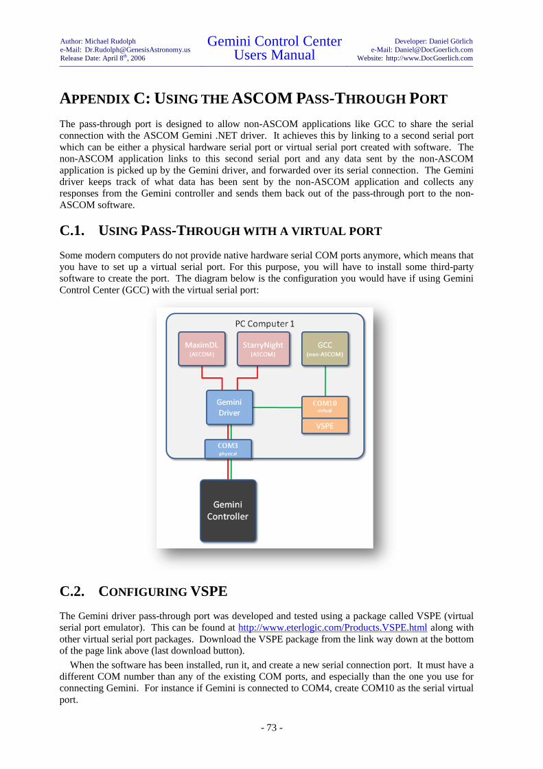
Author: Michael Rudolph
e-Mail: [email protected]
Release Date: April 8th, 2006
Gemini Control Center Users Manual
Developer: Daniel Görlich
e-Mail: [email protected]
Website: http://www.DocGoerlich.com
- 73 -
APPENDIX C: USING THE ASCOM PASS-THROUGH PORT
The pass-through port is designed to allow non-ASCOM applications like GCC to share the serial
connection with the ASCOM Gemini .NET driver. It achieves this by linking to a second serial port
which can be either a physical hardware serial port or virtual serial port created with software. The
non-ASCOM application links to this second serial port and any data sent by the non-ASCOM
application is picked up by the Gemini driver, and forwarded over its serial connection. The Gemini
driver keeps track of what data has been sent by the non-ASCOM application and collects any
responses from the Gemini controller and sends them back out of the pass-through port to the non-
ASCOM software.
C.1. USING PASS-THROUGH WITH A VIRTUAL PORT
Some modern computers do not provide native hardware serial COM ports anymore, which means that
you have to set up a virtual serial port. For this purpose, you will have to install some third-party
software to create the port. The diagram below is the configuration you would have if using Gemini
Control Center (GCC) with the virtual serial port:
C.2. CONFIGURING VSPE
The Gemini driver pass-through port was developed and tested using a package called VSPE (virtual
serial port emulator). This can be found at http://www.eterlogic.com/Products.VSPE.html along with
other virtual serial port packages. Download the VSPE package from the link way down at the bottom
of the page link above (last download button).
When the software has been installed, run it, and create a new serial connection port. It must have a
different COM number than any of the existing COM ports, and especially than the one you use for
connecting Gemini. For instance if Gemini is connected to COM4, create COM10 as the serial virtual
port.
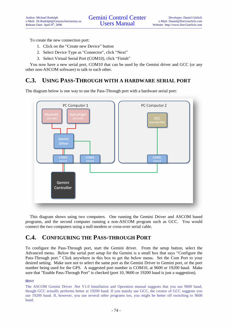
Author: Michael Rudolph
e-Mail: [email protected]
Release Date: April 8th, 2006
Gemini Control Center Users Manual
Developer: Daniel Görlich
e-Mail: [email protected]
Website: http://www.DocGoerlich.com
- 74 -
To create the new connection port:
1. Click on the “Create new Device” button
2. Select Device Type as "Connector", click “Next”
3. Select Virtual Serial Port (COM10), click “Finish”
You now have a new serial port, COM10 that can be used by the Gemini driver and GCC (or any
other non-ASCOM software) to talk to each other.
C.3. USING PASS-THROUGH WITH A HARDWARE SERIAL PORT
The diagram below is one way to use the Pass-Through port with a hardware serial port:
This diagram shows using two computers. One running the Gemini Driver and ASCOM based
programs, and the second computer running a non-ASCOM program such as GCC. You would
connect the two computers using a null-modem or cross-over serial cable.
C.4. CONFIGURING THE PASS-THROUGH PORT
To configure the Pass-Through port, start the Gemini driver. From the setup button, select the
Advanced menu. Below the serial port setup for the Gemini is a small box that says “Configure the
Pass-Through port.” Click anywhere in this box to get the below menu. Set the Com Port to your
desired setting. Make sure not to select the same port as the Gemini Driver to Gemini port, or the port
number being used for the GPS. A suggested port number is COM10, at 9600 or 19200 baud. Make
sure that "Enable Pass-Through Port" is checked (port 10, 9600 or 19200 baud is just a suggestion).
HINT
The ASCOM Gemini Driver .Net V1.0 Installation and Operation manual suggests that you use 9600 baud,
though GCC actually performs better at 19200 baud. If you mainly use GCC, the creator of GCC suggests you
use 19200 baud. If, however, you use several other programs too, you might be better off switching to 9600
baud.

Author: Michael Rudolph
e-Mail: [email protected]
Release Date: April 8th, 2006
Gemini Control Center Users Manual
Developer: Daniel Görlich
e-Mail: [email protected]
Website: http://www.DocGoerlich.com
- 75 -
Connect the Gemini driver to Gemini. Then, start GCC (or other non-ASCOM software) and select
COM10 as the port to use to connect to Gemini. Then, connect GCC to the telescope.
You should now have both, GCC and Gemini driver connected to Gemini controller. You can start
PemPro, TheSky, and any other software you like that uses the ASCOM driver, and they will all
continue to work while GCC is still connected and controlling Gemini.
HINT
When using GCC with Gemini Telescope .Net and the virtual pass-through port, GCC will only scan ports
COM1 through COM12 to find your Gemini. So if you are planning on using GCC ensure that you limit your
virtual port to the range COM1 through COM12.
COPYRIGHT NOTE
Appendix C of this manual has been copied with permission from the ASCOM Gemini Driver .Net V1.0
Installation and Operation manual, chapter 4.9. Please be aware that newer versions of the ASCOM driver and
its manual are not reflected in this appendix.
Author: Michael Rudolph
e-Mail: [email protected]
Release Date: April 8th, 2006
Gemini Control Center Users Manual
Developer: Daniel Görlich
e-Mail: [email protected]
Website: http://www.DocGoerlich.com
- 76 -
NOTES