A Combined Approach for Supporting the Business Process ...aditya/papers/pacis06/PACIS06-pp.pdf ·...
14
A Combined Approach for Supporting the Business Process Model Lifecycle (Preprint) George Koliadis Aleksandar Vranesevic Moshiur Bhuiyan Aneesh Krishna Aditya Ghose School of IT and Computer Science, University of Wollongong (UOW), Australia {gk56, av85, mmrb95, ak86, aditya}@uow.edu.au Business processes evolve throughout their lifecycle of change. Business Process Modeling (BPM 2 ) notations such as BPMN are used to effectively conceptualize and communicate important process characteristics to relevant stakeholders. Agent-oriented conceptual modeling notations, such as i*, effectively capture and communicate organizational context. In this paper we argue that the management of change throughout the business process model lifecycle can be more effectively supported by combining notations. In particular, we identify two potential sources of process change, one occurring within the organizational context and the other within the operational context. As such the focus in this paper is on the co-evolution of operational (BPMN) and organizational (i*) models. Our intent is to provide a way of expressing changes, which arise in one model, effectively in the other model. We present constrained development methodologies capable of guiding an analyst when reflecting changes from an i* model to a BPMN model and vice-versa. Keywords: Business Process Modeling, Lifecycle Management 1. Introduction Business process models play a key role in both organizational management (Smith et. al. 2003; Hammer et. al. 1993) and enterprise information systems development (Dumas et. al. 2005). They provide an effective means for communicating organizational context in terms of the configuration of activities enrolled by capable actors within an organization. Many notations have been developed for the task of modeling business processes, and each have their own focus of application and appropriate audience (Bider et. al. 2002; Kavakli 1999; Katzenstein et. al. 2000; Yu 1995b). In particular, high-level conceptual models provide an understanding of an organization from an intentional and social perspective (Yu 1995a) for reasoning support during redesign (Yu 1995a). In comparison, lower-level technical models are especially suited for applications in the description, execution and simulation of business processes (Yu 1995b). We need to base business process development on principled high-level models of the enterprise and the business context. Commonly, processes are formulated in an ad-hoc fashion without reference to these high-level models. Some of the most prominent modeling notations enlisted are primarily focused towards technically-oriented data, and process modeling notations such as ER, Data-Flow, Systems Flowcharting and UML and workflow modeling (Davies et. al. 2004). In this work, we offer constrained development methodologies to guide the development of process models from higher-level conceptual models. This supports life-cycle management in the following sense: when changes occur to the high-level model, these can be reflected in the process model, and vice-versa.
Transcript of A Combined Approach for Supporting the Business Process ...aditya/papers/pacis06/PACIS06-pp.pdf ·...
A Combined Approach for Supporting the Business Process Model Lifecycle (Preprint)
George Koliadis Aleksandar Vranesevic Moshiur Bhuiyan
Aneesh Krishna Aditya Ghose School of IT and Computer Science, University of Wollongong (UOW), Australia
{gk56, av85, mmrb95, ak86, aditya}@uow.edu.au Business processes evolve throughout their lifecycle of change. Business Process Modeling (BPM2) notations such as BPMN are used to effectively conceptualize and communicate important process characteristics to relevant stakeholders. Agent-oriented conceptual modeling notations, such as i*, effectively capture and communicate organizational context. In this paper we argue that the management of change throughout the business process model lifecycle can be more effectively supported by combining notations. In particular, we identify two potential sources of process change, one occurring within the organizational context and the other within the operational context. As such the focus in this paper is on the co-evolution of operational (BPMN) and organizational (i*) models. Our intent is to provide a way of expressing changes, which arise in one model, effectively in the other model. We present constrained development methodologies capable of guiding an analyst when reflecting changes from an i* model to a BPMN model and vice-versa.
Keywords: Business Process Modeling, Lifecycle Management
1. Introduction Business process models play a key role in both organizational management (Smith et. al. 2003; Hammer et. al. 1993) and enterprise information systems development (Dumas et. al. 2005). They provide an effective means for communicating organizational context in terms of the configuration of activities enrolled by capable actors within an organization. Many notations have been developed for the task of modeling business processes, and each have their own focus of application and appropriate audience (Bider et. al. 2002; Kavakli 1999; Katzenstein et. al. 2000; Yu 1995b). In particular, high-level conceptual models provide an understanding of an organization from an intentional and social perspective (Yu 1995a) for reasoning support during redesign (Yu 1995a). In comparison, lower-level technical models are especially suited for applications in the description, execution and simulation of business processes (Yu 1995b). We need to base business process development on principled high-level models of the enterprise and the business context. Commonly, processes are formulated in an ad-hoc fashion without reference to these high-level models. Some of the most prominent modeling notations enlisted are primarily focused towards technically-oriented data, and process modeling notations such as ER, Data-Flow, Systems Flowcharting and UML and workflow modeling (Davies et. al. 2004). In this work, we offer constrained development methodologies to guide the development of process models from higher-level conceptual models. This supports life-cycle management in the following sense: when changes occur to the high-level model, these can be reflected in the process model, and vice-versa.
In this paper, Section 2 provides a background to business process modeling with an overview of our chosen notations. An illustration of the modeling framework supported by the constrained development methodologies is outlined in Section 3. Section 4 illustrates concepts / methods provided in our methodologies (with examples). The paper is then concluded in Section 5.
2. Background In order to provide scope for a common understanding on business processes, we provide a definition based on the meanings in Smith et. al. 2003, Hammer et. al. 1993, and Davenport 1993. A Business Process is a set of dynamically coordinated activities, controlled by a number of socially dependant participants, aimed towards the achievement of a specific operational objective. Business Process Management (BPM1) is a re-emerging discipline, aimed towards supporting the effective (i.e. and automated Smith et. al. 2003) management of business processes within an organization through the use of specialized tools and methods. BPM1 promotes that a clear understanding through the explicit modeling of the processes underlying an organization is required to support effective organizational management/improvement practices (Harmon 2003). Business Process Modeling (BPM2) aims to conceptualize the characteristics of current or desired business processes in a common (preferably graphical) language/notation that can be communicated to all stakeholders including business users (i.e. executives, analysts, partners, managers and first line workers etc.) and technical users (i.e. systems/network architects, programmers and support staff etc.). Added benefits arise when the models can be translated to ‘process code’ (Fischer 2005; OASIS 2006) that can be understood by ‘process-aware information systems’ (Dumas et. al. 2005), effectively accelerating the change process. The notations used for modeling business processes have been categorized in many works, based on their conceptual features (Bider et. al. 2002; Kavakli 1999; Loucopoulos 1995; Katzenstein et. al. 2000; Yu 1995b). The common principle recognized in all analyses is that some notations are more suited towards specific audiences (i.e. with either technical/non-technical backgrounds) or applications (i.e. possibly for description, re-design or execution) throughout the business process lifecycle. Many notations focus on specific aspects, with limited relation/traceability to other important business process aspects. This has brought about the need for an integrated view (Green et. al. 2000) to support the development and maintenance of rich models that provide an enhanced ability to conceptualize, communicate and understand business processes, and their context of operation. Our argument is that in order to effectively conceptualize business process, we need to base the development of business process models on principled high-level contextual models of the enterprise that illustrate its motivations, resources, and internal/external social/strategic inter-dependencies. Moreover, any purposeful changes made to business process models must be reflected within the high-level model for analysis against the greater context of the enterprise. To support an analyst in achieving this task, we offer a modeling framework supported by constrained development methodologies that can guide an analyst during the design of process models given a high-level conceptual models and vice-versa. We take the following approach to lifecycle management: when changes to a business process model (i.e. BPMN – White 2004) occur, these changes must ensure some notion of consistency with a higher-level enterprise model. In this instance an i* model (Yu 1995a). We compare our approach to previous work below.
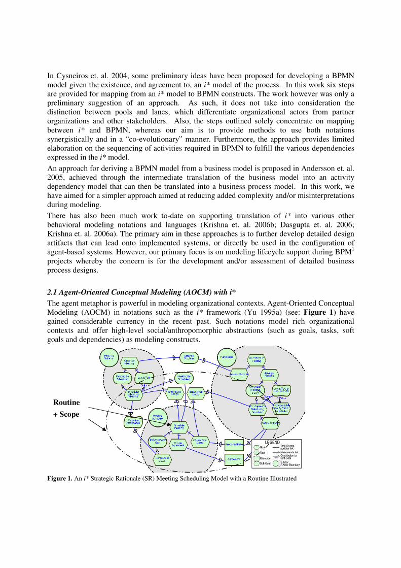
In Cysneiros et. al. 2004, some preliminary ideas have been proposed for developing a BPMN model given the existence, and agreement to, an i* model of the process. In this work six steps are provided for mapping from an i* model to BPMN constructs. The work however was only a preliminary suggestion of an approach. As such, it does not take into consideration the distinction between pools and lanes, which differentiate organizational actors from partner organizations and other stakeholders. Also, the steps outlined solely concentrate on mapping between i* and BPMN, whereas our aim is to provide methods to use both notations synergistically and in a “co-evolutionary” manner. Furthermore, the approach provides limited elaboration on the sequencing of activities required in BPMN to fulfill the various dependencies expressed in the i* model. An approach for deriving a BPMN model from a business model is proposed in Andersson et. al. 2005, achieved through the intermediate translation of the business model into an activity dependency model that can then be translated into a business process model. In this work, we have aimed for a simpler approach aimed at reducing added complexity and/or misinterpretations during modeling. There has also been much work to-date on supporting translation of i* into various other behavioral modeling notations and languages (Krishna et. al. 2006b; Dasgupta et. al. 2006; Krishna et. al. 2006a). The primary aim in these approaches is to further develop detailed design artifacts that can lead onto implemented systems, or directly be used in the configuration of agent-based systems. However, our primary focus is on modeling lifecycle support during BPM1 projects whereby the concern is for the development and/or assessment of detailed business process designs. 2.1 Agent-Oriented Conceptual Modeling (AOCM) with i* The agent metaphor is powerful in modeling organizational contexts. Agent-Oriented Conceptual Modeling (AOCM) in notations such as the i* framework (Yu 1995a) (see: Figure 1) have gained considerable currency in the recent past. Such notations model rich organizational contexts and offer high-level social/anthropomorphic abstractions (such as goals, tasks, soft goals and dependencies) as modeling constructs.
Figure 1. An i* Strategic Rationale (SR) Meeting Scheduling Model with a Routine Illustrated
Routine + Scope
It has been argued that notations such as i* help answer questions such as what goals exist, how key actors depend on each other and what alternatives must be considered. Furthermore, i* has been acknowledged as illustrating the key social/strategic inter-relationships between actors (Yu 1995a; Katzenstein et. al. 2000) required for effective business process redesign. This is achieved via support for reasoning about organizational activities and their assignment to various organizational agents (Loucopoulos 1995) in respect to: the ability, workability, viability, and believability of their routines; and, level of commitment (Yu 1995a). Figure 1 represents a simple i* Meeting Scheduling model that will be used to illustrate the first constrained development methodology for developing a BPMN model outlined in a subsequent section. The central concept in i* is that of intentional actor. These can be seen in the Meeting Scheduling model as nodes representing the intentional/social relationships between three (3) actors required to schedule a meeting: a Meeting Initiator (MI); Meeting Scheduler (MS); and, Meeting Participant (MP). The i* framework consists of two modeling components (Yu 1995a): Strategic Dependency (SD) Models and Strategic Rationale (SR) Models. The SD model consists of a set of nodes and links. Each node represents an actor, and each link between the two actors indicates that one actor depends on the other for something (i.e. goals, task, resource, and soft-goal) in order that the former may attain some goal. The depending actor is known as depender, while the actor depended upon is known as the dependee. The object around which the dependency relationship centers is called the dependum. The SR mode further represents internal motivations and capabilities (i.e. processes or routines) accessible to specific actors that ensure dependencies can be met. The intentional properties of an agent such as goals (e.g. to ‘FindAnAgreeableSlot’), beliefs, abilities (e.g. to ‘MergeAvailableDates’) and commitments (e.g. to ‘MaximizeAttendance’) are used in i* for modeling organizations (Yu 1995a). Actors are [inter]related through dependencies that may involve goals to be achieved (e.g. MeetingBeScheduled), tasks to be performed (e.g. EnterAvailDates), resources to be furnished (e.g. Agreement), or soft-goals (optimization objectives or preferences) to be satisficed (e.g. MaximizeAttendance). In i*, a routine (Yu 1995a) specifies an intended course of action an actor may pursue given a set of alternatives. These elements and their relationships represent the strategic requirements of a process when invoked in a specific context. For example, to ScheduleMeeting (illustrated in Figure 1 with its Scope) that includes three sub-tasks and six dependencies with two additional actors. Tasks in i* may be primitively workable whereny the actor responsible for the element believes that it can achieve its requirements at execution time – i.e. it is sufficiently reduced during decomposition. In comparison to BPMN however, a primitively workable element may still be represented as a sub-process as the term does not imply a ‘primitively executable action’ (i.e. application of analyst / designer discretion). Furthermore, for a routine to be workable, all involved actors must be committed to satisfying their dependencies (Yu 1995a). 2.2 Business Process Modeling (BPM2) with BPMN Many existing BPM2 notations primarily focus on technical process aspects including the flow of activity execution/information and/or resource usage/consumption (Loucopoulos 1995). This perspective is aimed at describing the sequence of activities, events and decisions that are made during process execution, however social and intentional components lack representation. The technical focus of these notations is especially suited for applications in the description,

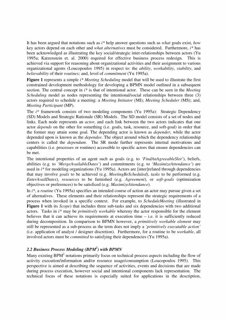
execution and simulation of business processes but is lacking in support for process redesign and improvement (Yu 1995b). One such notation is the Business Process Modeling Notation (BPMN), developed by the Business Process Management Initiative (BPMI.org). BPMN can be seen as primarily a technically-oriented notation that is augmented with an ability to assign activity execution control to entities (e.g. roles) within an organization with ‘swim-lanes’. This effectively provides a view of the responsibilities and required communications between classes of process participants, but does not provide a view of other social and intentional characteristics including the goals of participants and their inter-dependencies.
Figure 2. A BPMN ‘Patient Treatment’ Process Model
Figure 2 represents a simple BPMN Patient Treatment process that will be used in sections below to illustrate the constrained development of an initial i* model. Processes are represented in BPMN using flow nodes: events (circles), activities (rounded boxes), and decisions (diamonds); connecting objects: control flow links (unbroken directed lines), and message flow links (broken directed lines); and swim-lanes: pools (high-level rectangular container), and lanes partitioning pools. These concepts are further discussed within (White 2004). Since its initial publication (White 2004), BPMN has been accepted by the greater BPM1 community (Smith et. al. 2003; Becker et. al. 2005), due to its expressiveness and ability to map directly to executable process languages including XPDL (Fischer 2005) and BPEL (White 2004; Ouyang et. al. 2006). The wide uptake of the notation by most BPM2 tool vendors is also a sign of its longevity (Hall et. al. 2005). Some practitioners have hailed BPMN as supplying a rich representation that allows Business Process Management Systems (BPMS) the ability to control the required interactions with humans and 3rd party applications (Miers 2004). Furthermore, an analysis of BPMN (Becker et. al. 2005) also stated its high maturity in representing concepts required for modeling business process, apart from some limitations in terms of representing state, and the possible ambiguity of the swim-lane concept.
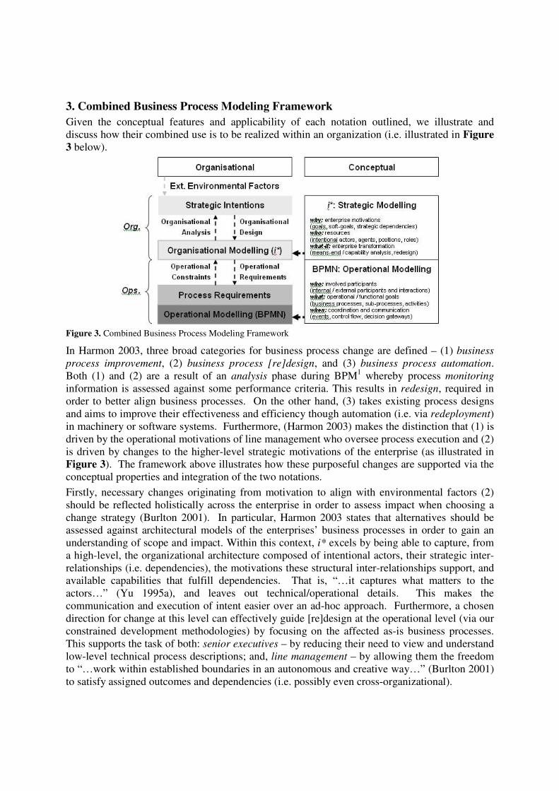
3. Combined Business Process Modeling Framework Given the conceptual features and applicability of each notation outlined, we illustrate and discuss how their combined use is to be realized within an organization (i.e. illustrated in Figure 3 below).
Figure 3. Combined Business Process Modeling Framework
In Harmon 2003, three broad categories for business process change are defined – (1) business process improvement, (2) business process [re]design, and (3) business process automation. Both (1) and (2) are a result of an analysis phase during BPM1 whereby process monitoring information is assessed against some performance criteria. This results in redesign, required in order to better align business processes. On the other hand, (3) takes existing process designs and aims to improve their effectiveness and efficiency though automation (i.e. via redeployment) in machinery or software systems. Furthermore, (Harmon 2003) makes the distinction that (1) is driven by the operational motivations of line management who oversee process execution and (2) is driven by changes to the higher-level strategic motivations of the enterprise (as illustrated in Figure 3). The framework above illustrates how these purposeful changes are supported via the conceptual properties and integration of the two notations. Firstly, necessary changes originating from motivation to align with environmental factors (2) should be reflected holistically across the enterprise in order to assess impact when choosing a change strategy (Burlton 2001). In particular, Harmon 2003 states that alternatives should be assessed against architectural models of the enterprises’ business processes in order to gain an understanding of scope and impact. Within this context, i* excels by being able to capture, from a high-level, the organizational architecture composed of intentional actors, their strategic inter-relationships (i.e. dependencies), the motivations these structural inter-relationships support, and available capabilities that fulfill dependencies. That is, “…it captures what matters to the actors…” (Yu 1995a), and leaves out technical/operational details. This makes the communication and execution of intent easier over an ad-hoc approach. Furthermore, a chosen direction for change at this level can effectively guide [re]design at the operational level (via our constrained development methodologies) by focusing on the affected as-is business processes. This supports the task of both: senior executives – by reducing their need to view and understand low-level technical process descriptions; and, line management – by allowing them the freedom to “…work within established boundaries in an autonomous and creative way…” (Burlton 2001) to satisfy assigned outcomes and dependencies (i.e. possibly even cross-organizational).

Secondly, change is supported at the operational level by allowing for creativity and communication of intent. The operations of an enterprise can be described by involved resources (e.g. human, IT), their capabilities and required coordination/execution – something BPMN is well suited for. Any changes proposed at the operational level can be assessed against their requirements at the organizational level. Where a requirement may not be fulfilled by some proposed change, the line manager may either: (1) choose to take an alternative course of action given they agree with their requirements and available resources; or (2) query the intent of their requirements with executive management. This may in turn impact on processes that cross the enterprise, requiring a change in other areas in order to re-align processes. Both these tasks are guided by the constrained development methodologies outlined below.
4. Constrained Development Methodologies We propose constrained development methodologies to guide the derivation or maintenance of one type of model given the availability of the other. The development is supported with the introduction of two new concepts: fulfillment conditions (i.e. as in Fuxman et. al. 2004) and effect annotations. 4.1 Concepts These concepts form the basis for our methodologies and are introduced as annotations to either an i* or BPMN model. Effect Annotations. An effect is broadly defined as the result (i.e. product or outcome) of an activity being executed by some cause or agent. An effect annotation is a specific statement relating to the outcome of an activity, associated to a state altering construct in a given model. They indicate the achievement of certain conditions aimed towards (i.e. and possibly required for) some higher order objective. During BPM2, effects are annotated to atomic tasks/activities or sub-processes within an actor’s lane. Effects are also cumulative. The execution of a number of activities in succession results in a cumulative effect that includes the specific effects of each activity in the sequence. We also note the fact that certain effects can undo prior effects (i.e. in the case of compensatory activities). An effect annotation includes: a label that generalizes the effect (e.g. ‘CustomerDetailsStored’); a designation specifying whether the effect is a normal (i.e. desired) outcome for an activity (e.g. ‘RegistrationValidated’), or a abnormal (i.e. undesired) outcome for the activity that may require the application of some mitigation strategy; an optional informal definition describing the effect in relation to the result achieved in its environment (e.g. ‘The details relating to the current customer have been stored within the system.’); an optional formal definition may be used to define achieved states in a chosen formalism. Effect annotations may possibly be formalized using the formal layers of some currently well-developed Goal-Oriented Requirements Engineering (GORE) methodologies including Formal Tropos (Fuxman et. al. 2004) or KAOS (Lamsweerde 2001). Effectively this provides a multi-layered approach that may allow for automated analysis with the use of model checking. However, we only discuss its applicability in this work, and aim towards its development in the future.
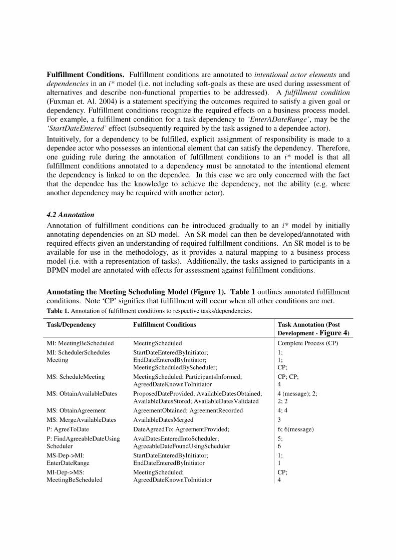
Fulfillment Conditions. Fulfillment conditions are annotated to intentional actor elements and dependencies in an i* model (i.e. not including soft-goals as these are used during assessment of alternatives and describe non-functional properties to be addressed). A fulfillment condition (Fuxman et. Al. 2004) is a statement specifying the outcomes required to satisfy a given goal or dependency. Fulfillment conditions recognize the required effects on a business process model. For example, a fulfillment condition for a task dependency to ‘EnterADateRange’, may be the ‘StartDateEntered’ effect (subsequently required by the task assigned to a dependee actor). Intuitively, for a dependency to be fulfilled, explicit assignment of responsibility is made to a dependee actor who possesses an intentional element that can satisfy the dependency. Therefore, one guiding rule during the annotation of fulfillment conditions to an i* model is that all fulfillment conditions annotated to a dependency must be annotated to the intentional element the dependency is linked to on the dependee. In this case we are only concerned with the fact that the dependee has the knowledge to achieve the dependency, not the ability (e.g. where another dependency may be required with another actor). 4.2 Annotation Annotation of fulfillment conditions can be introduced gradually to an i* model by initially annotating dependencies on an SD model. An SR model can then be developed/annotated with required effects given an understanding of required fulfillment conditions. An SR model is to be available for use in the methodology, as it provides a natural mapping to a business process model (i.e. with a representation of tasks). Additionally, the tasks assigned to participants in a BPMN model are annotated with effects for assessment against fulfillment conditions. Annotating the Meeting Scheduling Model (Figure 1). Table 1 outlines annotated fulfillment conditions. Note ‘CP’ signifies that fulfillment will occur when all other conditions are met. Table 1. Annotation of fulfillment conditions to respective tasks/dependencies.
Task/Dependency Fulfillment Conditions Task Annotation (Post Development - Figure 4)
MI: MeetingBeScheduled MeetingScheduled Complete Process (CP) MI: SchedulerSchedules Meeting
StartDateEnteredByInitiator; EndDateEnteredByInitiator; MeetingScheduledByScheduler;
1; 1; CP;
MS: ScheduleMeeting MeetingScheduled; ParticipantsInformed; AgreedDateKnownToInitiator
CP; CP; 4
MS: ObtainAvailableDates ProposedDateProvided; AvailableDatesObtained; AvailableDatesStored; AvailableDatesValidated
4 (message); 2; 2; 2
MS: ObtainAgreement AgreementObtained; AgreementRecorded 4; 4 MS: MergeAvailableDates AvailableDatesMerged 3 P: AgreeToDate DateAgreedTo; AgreementProvided; 6; 6(message) P: FindAgreeableDateUsing Scheduler
AvalDatesEnteredIntoScheduler; AgreeableDateFoundUsingScheduler
5; 6
MS-Dep->MI: EnterDateRange
StartDateEnteredByInitiator; EndDateEnteredByInitiator
1; 1
MI-Dep->MS: MeetingBeScheduled
MeetingScheduled; AgreedDateKnownToInitiator
CP; 4
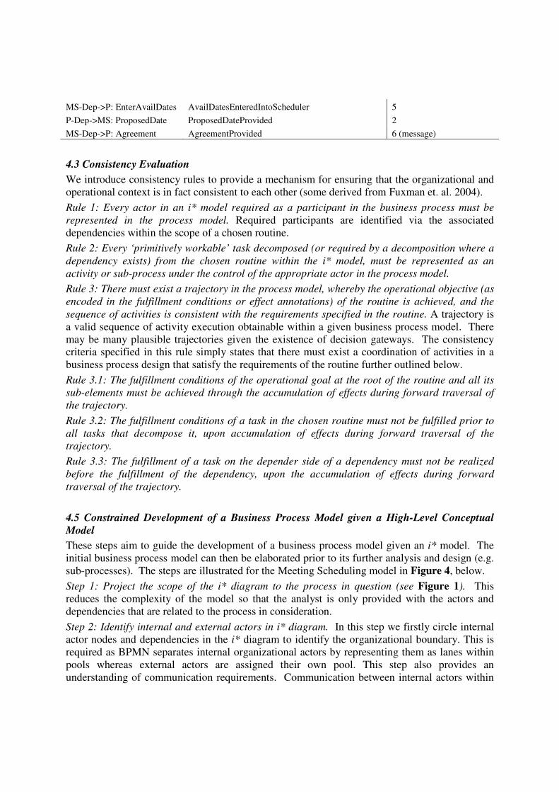
MS-Dep->P: EnterAvailDates AvailDatesEnteredIntoScheduler 5 P-Dep->MS: ProposedDate ProposedDateProvided 2 MS-Dep->P: Agreement AgreementProvided 6 (message)
4.3 Consistency Evaluation We introduce consistency rules to provide a mechanism for ensuring that the organizational and operational context is in fact consistent to each other (some derived from Fuxman et. al. 2004). Rule 1: Every actor in an i* model required as a participant in the business process must be represented in the process model. Required participants are identified via the associated dependencies within the scope of a chosen routine. Rule 2: Every ‘primitively workable’ task decomposed (or required by a decomposition where a dependency exists) from the chosen routine within the i* model, must be represented as an activity or sub-process under the control of the appropriate actor in the process model. Rule 3: There must exist a trajectory in the process model, whereby the operational objective (as encoded in the fulfillment conditions or effect annotations) of the routine is achieved, and the sequence of activities is consistent with the requirements specified in the routine. A trajectory is a valid sequence of activity execution obtainable within a given business process model. There may be many plausible trajectories given the existence of decision gateways. The consistency criteria specified in this rule simply states that there must exist a coordination of activities in a business process design that satisfy the requirements of the routine further outlined below. Rule 3.1: The fulfillment conditions of the operational goal at the root of the routine and all its sub-elements must be achieved through the accumulation of effects during forward traversal of the trajectory. Rule 3.2: The fulfillment conditions of a task in the chosen routine must not be fulfilled prior to all tasks that decompose it, upon accumulation of effects during forward traversal of the trajectory. Rule 3.3: The fulfillment of a task on the depender side of a dependency must not be realized before the fulfillment of the dependency, upon the accumulation of effects during forward traversal of the trajectory. 4.5 Constrained Development of a Business Process Model given a High-Level Conceptual Model These steps aim to guide the development of a business process model given an i* model. The initial business process model can then be elaborated prior to its further analysis and design (e.g. sub-processes). The steps are illustrated for the Meeting Scheduling model in Figure 4, below. Step 1: Project the scope of the i* diagram to the process in question (see Figure 1). This reduces the complexity of the model so that the analyst is only provided with the actors and dependencies that are related to the process in consideration. Step 2: Identify internal and external actors in i* diagram. In this step we firstly circle internal actor nodes and dependencies in the i* diagram to identify the organizational boundary. This is required as BPMN separates internal organizational actors by representing them as lanes within pools whereas external actors are assigned their own pool. This step also provides an understanding of communication requirements. Communication between internal actors within

pools is implied, whereas communication between internal and external participants is explicitly stated with message flow links in BPMN. Step 3: Map elements to equivalent constructs within the BPMN model. See sub-steps below.
Step3.1: Map Participants. The greater organization for which the i* model is represented is signified as a pool in BPMN. Any external participants are also represented as pools. Internal organizational actors are represented as lanes within the organizational pool. There must be an initiating actor in the process model that is identified by the placement of a start event within the respective actor’s pool or lane. The initiator is identified as having responsibility over the execution of the routine in the i* model.
Step 3.2: Map Activities. ‘Primitively workable’ tasks within i* are represented as either sub-processes or atomic activities within BPMN assigned to actors within pools and lanes. Step 4: Sequence required tasks/sub-processes and introduce control and sequence flow links by analyzing fulfillment conditions. Tasks placed within each pool or lane are now sequenced to conform to routine requirements by taking Consistency Rule 3 (see: Section 4.3) into consideration. This requires that tasks be sequenced using control flow links in a manner that results in a trajectory satisfying fulfillment conditions on an i*model. Control flow links are also introduced to realize dependencies between actors within the same organization. A sequence flow link is used to represent the dependency going from the depender lane to the dependee lane. In order to realize dependencies between organizational boundaries, a message flow link is used to represent the dependency going from the depender lane to the dependee lane. This may require single/multiple messages between tasks derived via analysis of fulfillment conditions and required effects. Step 6: Elaborate on sub-processes. The choice to introduce tasks or sub-processes into the BPMN diagram for specific tasks in the i* model is made in Step 4. The analyst can develop each sub-process guided by the list of required fulfillment conditions annotated to the i* task that the sub-process realizes. Constrained Development of a Meeting Scheduling BPMN Model.
Figure 4. BPMN Process Model derived using the constrained development methodology
Step 1 & 2: Internal / External Participant Pools
Step 4: Task Sequencing, Message and Sequence Flow
Step 3: Participants and Activities
1
2 3 4
5 6
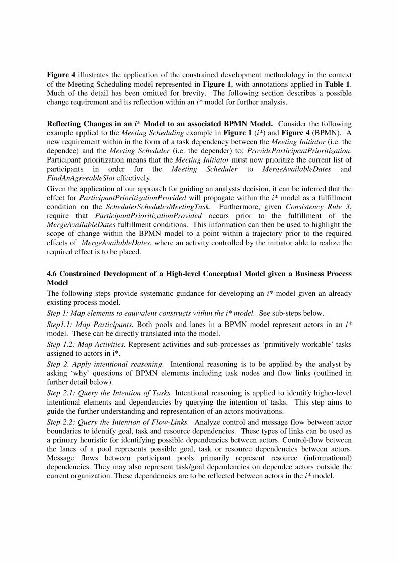
Figure 4 illustrates the application of the constrained development methodology in the context of the Meeting Scheduling model represented in Figure 1, with annotations applied in Table 1. Much of the detail has been omitted for brevity. The following section describes a possible change requirement and its reflection within an i* model for further analysis. Reflecting Changes in an i* Model to an associated BPMN Model. Consider the following example applied to the Meeting Scheduling example in Figure 1 (i*) and Figure 4 (BPMN). A new requirement within in the form of a task dependency between the Meeting Initiator (i.e. the dependee) and the Meeting Scheduler (i.e. the depender) to: ProvideParticipantPrioritization. Participant prioritization means that the Meeting Initiator must now prioritize the current list of participants in order for the Meeting Scheduler to MergeAvailableDates and FindAnAgreeableSlot effectively. Given the application of our approach for guiding an analysts decision, it can be inferred that the effect for ParticipantPrioritizationProvided will propagate within the i* model as a fulfillment condition on the SchedulerSchedulesMeetingTask. Furthermore, given Consistency Rule 3, require that ParticipantPrioritizationProvided occurs prior to the fulfillment of the MergeAvailableDates fulfillment conditions. This information can then be used to highlight the scope of change within the BPMN model to a point within a trajectory prior to the required effects of MergeAvailableDates, where an activity controlled by the initiator able to realize the required effect is to be placed. 4.6 Constrained Development of a High-level Conceptual Model given a Business Process Model The following steps provide systematic guidance for developing an i* model given an already existing process model. Step 1: Map elements to equivalent constructs within the i* model. See sub-steps below. Step1.1: Map Participants. Both pools and lanes in a BPMN model represent actors in an i* model. These can be directly translated into the model. Step 1.2: Map Activities. Represent activities and sub-processes as ‘primitively workable’ tasks assigned to actors in i*. Step 2. Apply intentional reasoning. Intentional reasoning is to be applied by the analyst by asking ‘why’ questions of BPMN elements including task nodes and flow links (outlined in further detail below). Step 2.1: Query the Intention of Tasks. Intentional reasoning is applied to identify higher-level intentional elements and dependencies by querying the intention of tasks. This step aims to guide the further understanding and representation of an actors motivations. Step 2.2: Query the Intention of Flow-Links. Analyze control and message flow between actor boundaries to identify goal, task and resource dependencies. These types of links can be used as a primary heuristic for identifying possible dependencies between actors. Control-flow between the lanes of a pool represents possible goal, task or resource dependencies between actors. Message flows between participant pools primarily represent resource (informational) dependencies. They may also represent task/goal dependencies on dependee actors outside the current organization. These dependencies are to be reflected between actors in the i* model.

Step 3: Identify soft-goal dependencies in the i* model. The representation of soft-goals (including dependencies) are not in the scope of the BPMN notation. In order to identify soft-goals (including soft-goal dependencies between actors) intentional reasoning may also be used. Constrained Development of a Patient Treatment i* Model.
Figure 5. An i* ‘Patient Treatment’ Process
Figure 5 illustrates the constrained development of the Patient Treatment BPMN model in Figure 2. The section below describes how a change requirement may be reflected down to the business process model. Reflecting Changes in a BPMN Model to an associated i* Model. Consider now a scenario where the business process model is modified to improve the performance of the IssuePrescription task which has been identified to be a major operational bottleneck. The task is improved by including a task before hand which checks the patient’s previous medical history to identify previous prescriptions for the patient for similar illnesses such as for instance the common flue. We name the task CheckPatientMedicalHistory. Furthermore, the client is now encouraged to provide information on his medical background, which we represent as a task named ProvideMedicalHistory Information. We now proceed to add an additional task within the bounds of the Doctor agent and an additional task within the bounds of the Patient agent. As in the previous case we use intentional reasoning to argue that the added task, within the Doctor agent, contributes to the higher level task of TreatingPatients. We apply the same technique to justify the placement of the ProvideMedicalHistoryInformation task as a decomposition task under the RequestMedicine task. The added message flow in the BPMN diagram is represented as a resource dependency between the Patient and the Doctor, where the Doctor requires the Patient to provide his previous medical history.
Step 1: Pools and Lanes as Actors; Activities & Sub-Processes
Step 2: Querying Intentions – Tasks and Flow Links
Step 3: Analyze Message / Control Flow
As we move to identify the goal and soft-goal dependencies we use the process improvement information to structure the appropriate soft-goal. As a result there now exists a soft-goal between the Patient and the Doctor which is titled TimelyDrugPrescription, indicating the fact that the Doctor will try to improve the time required to prescribe medication to the Patient.
5. Conclusion In this work, we have illustrated our initial approach for supporting the lifecycle of business process models with the complementary use of i* - a well developed notation for modeling organizational contexts, and BPMN – a newly developed notation for modeling business processes. The approach for reflecting changes in organizational context to changes in the design of business processes provides an effective mechanism for aligning business processes with organizational objectives. Similarly, operational improvements can be mapped back to organizational objectives to facilitate analysis and ensure no conflicts exist with existing objectives. Although these steps are preliminary we believe their systematic nature makes them available for automation in all phases, and are pursuing this task, through the development of a software tool, along with further refinement of the approach.
References Andersson, B. Bergholtz, M. Edirisuriya, A. Ilayperuma, T. Johannesson, P. “A Declarative
Foundation of Process Models,” Lecture Notes in Computer Science, Volume 3520, pp. 233 – 247, Jan, 2005.
Becker, J. Indulska, M. and Rosemann, M. Green, P. “Do Process Modelling Techniques Get Better? A Comparative Ontological Analysis of BPMN,” in Campbell, Bruce and Underwood, Jim and Bunker, Deborah, Eds. Proceedings 16th Australasian Conference on Information Systems, Sydney, Australia, 2005.
Bider, I. Johannesson, P. “Tutorial on: Modeling Dynamics of Business Processes – Key for Building Next Generation of Business Information Systems,” in The 21st International Conference on Conceptual Modeling (ER2002), Tampere, FL, October 7-11, 2002.
Burlton, R. T. “Business Process Management – Profiting from Process,” Indianapolis, Sams Publishing, 2001.
Cysneiros, L.M. Yu, E. “Addressing Agent Autonomy in Business Process Management - with Case Studies on the Patient Discharge Process,” in Proc. of the 2004 Information Resources Management Association Conference, New Orleans, May, 2004.
Dasgupta, A., Salim, F., Krishna, A., Ghose, A. K. “Hybrid Modelling using i* and AgentSpeak (L) Agents in Agent-Oriented Software Engineering,” To appear in the Proceedings of 8th International Conference on Enterprise Information System (ICEIS-2006), Paphos, Cyprus, 23-27 May 2006.
Davenport, T. H. “Process Innovation: Reengineering Work through Information Technology,” Harvard Business School Press, 1993.
Davies, I, Green, P. Rosemann, M. Gallo, S. “Conceptual Modelling – What and Why in Current Practice,” Lecture Notes in Computer Science, Volume 3288, Pages 30 – 42, Jan 2004.
Dumas, M. Aalst, W. M. P. and Hofstede, A. H. “Process-Aware Information Systems: Bridging People and Software Through Process Technology,” Wiley-Interscience, 2005.
Fischer, L. “Workflow Handbook 2005,” Workflow Management Coalition, (WfMC), 2005. Fuxman, A. Liu, L. Mylopoulos, J. Pistore, M. Roveri, M. Traverso, P. “Specifying and
analyzing early requirements in Tropos,” Requirements Engineering, Springer London, Volume 9, Issue 2, 132 – 150, 2004.
Green, P & Rosemann, M. “Integrated Process Modeling: An Ontological Evaluation,” Information Systems, 25(2), pp. 73-87, 2000.
Hall, C. Harmon, P. “The 2005 Enterprise Architecture, Process Modeling & Simulation Tools Report,” Technical Report, bptends.com, 2005.
Hammer, M. Champy, J. “Reengineering the Corporation: A Manifesto for Business Revolution,” HarperBusiness, 1993.
Harmon, P. “Business Process Change,” San Francisco, CA: Morgan Kaufmann, 2003. Katzenstein G. Lerch F. J. (2000). “Beneath the surface of organizational processes: a social
representation framework for business process redesign,” ACM Transactions on Information Systems (TOIS), 18(4), (pp. 383-422).
Kavakli, V. and Loucopoulos, P. “Goal-Driven Business Process Analysis - Application in Electricity Deregulation,” Information Systems, Vol 24, No3, pp. 187-207, 1999.
Krishna, A., Ghose, A. K., Vranesevic, A. “Loosely-coupled Consistency between Agent-Oriented Conceptual Models and UML Sequence Diagrams,” Special issue on Agent-Oriented Software Development Methodologies in International Journal of Multi-Agent and Grid Systems (Accepted), 2006b.
Krishna, A., Guan, Y., Sambattheera, C., Ghose, A. K. “Agent-based Prototyping of Web-based Systems,” To appear in the Proceedings of the 19th International Conference on Industrial and Engineering Applications of Artificial Intelligence and Expert Systems (IEA-AIE-2006), Springer-Verlag Lecture Notes in Computer Science, Annecy, France, 27-30 June 2006a.
Lamsweerde, A. “Goal-Oriented Requirements Engineering: A Guided Tour,” In: The 5th International Symp. In Requirements Engineering (RE’01), Aug. 2001.
Miers, D. “The Split Personality of BPM,” Business Process Trends, bptrends.com, 2004. OASIS. “Web Services Business Process Execution Language,” (WS-BPEL) 2.0, 2006. Ouyang, C. W.M.P. van der Aalst, Dumas, M. and ter Hofstede, A.H.M. “Translating BPMN to
BPEL,” BPM Center Report BPM-06-02, BPMcenter.org, 2006. Loucopoulos, P. and Kavakli, E. “Enterprise Modeling and the Teleological Approach to
Requirements Engineering,” International Journal of Intelligent and Cooperative Information Systems, Vol 4, No1, pp. 45-79, 1995.
Smith, H. Fingar, P. “Business Process Management – The Third Wave,” Tampa, FL: Meghan-Kiffer Press, 2003.
White, S. “Business Process Modeling Notation (BPMN),” Version 1.0, Business Process Management Initiative (BPMI.org), May 2004.
Yu, E. “Modelling Strategic Relationships for Process Reengineering,” PhD Thesis, Graduate Department of Computer Science, University of Toronto, Toronto, Canada, pp.~124, 1995a.
Yu, E. “Models for Supporting the Redesign of Organizational Work,” Proceedings, Conf. on Organizational Computing Systems (COOCS'95) August 13-16, Milpitas, California, USA. pp. 225-236, 1995b.