A Case Study on Thailand’s New Teleprotection …... This research paper presents the new idea of...
10
Received: April 25, 2017 20 International Journal of Intelligent Engineering and Systems, Vol.10, No.6, 2017 DOI: 10.22266/ijies2017.1231.03 A Case Study on Thailand’s New Teleprotection Regulation: Direct Transfer Trip Application in Distributed Generation Network Naradon Chotiwanaporn 1 Chow Chompoo-Inwai 1 * 1 Electrical Engineering Department, Faculty of Engineering, King Mongkut’s Institute of Technology Ladkrabang, Bangkok, 10520, Thailand * Corresponding author’s Email: [email protected] Abstract: This research paper presents the new idea of applying the transmission line teleprotection scheme called direct transfer trip (DTT) technique to use with a closed-loop distribution network. A large-scale 163MW gas turbine power plant connected to a three-substation closed-loop distribution network was chosen to be a case study here. A newly-proposed DTT configuration, DTT logic diagram and circuit breaker trip matrix had been redesigned and presented in this paper. For the proposed DTT configuration, several remote terminal units will be installed at every substation connected to the distribution network, whereas the logic controller will be installed at the selected power plant. A huge advantage over the conventionally-installed zoning peer-to-peer protection scheme is that the proposed DTT logic controller is able to almost instantaneously compute and send out the clearing faults command, regardless of fault locations in this particular closed-loop distribution network, while the conventional one cannot in many cases. Additional benefit is that the proposed DTT teleprotection scheme completely prevent the generators from operation in island mode resulting in minimal lost and damages caused from this circumstance. The relay test tool is used to verify the proposed DTT protective capabilities and speed. The simulation and commissioning test results confirm the proper functionality of the proposed technique. The implementation to the real field has been done and presented here as well. What we have learned from this case study shall be a very good guideline for other similar circumstances. Keywords: Direct transfer trip, Teleprotection, Island mode, IEC-60834, IEEE-1547, IEEE-C37.236. 1. Introduction 1.1 Electric utilities in Thailand In Thailand, three state utilities are responsible for the overall country’s electrical power system namely EGAT (the Electricity generating authority of Thailand), MEA (the Metropolitan electricity), and PEA (the Provincial electricity authority). EGAT is mainly responsible for generations and high voltage transmission line systems. MEA is responsible for the metropolitan area’s distribution and medium to low voltage transmission system. And PEA is responsible for the rest of the country’s distribution and medium to low transmission line systems. According to Thailand Power Development Plan (PDP), governed by the Ministry of Energy, Thai government launched the new policy to enhance Thailand’s electrical power system stability and security by purchasing more electrical power from local private sectors i.e., Independent power producers (IPP), Small power producers (SPP) and Very small power producers (VSPP) [1]. EGAT is responsible for purchasing electrical power from IPPs and SPPs, while PEA is responsible for purchasing from IPPs, SPPs and VSPPs, whereas MEA is responsible for purchasing from only VSPPs. Each utility has its own policy and regulations in electricity purchasing. All of the power purchase agreement (PPA) owners have an option to connect and sell electricity to only one utility. IPPs or SPPs owner can choose between
Transcript of A Case Study on Thailand’s New Teleprotection …... This research paper presents the new idea of...

Received: April 25, 2017 20
International Journal of Intelligent Engineering and Systems, Vol.10, No.6, 2017 DOI: 10.22266/ijies2017.1231.03
A Case Study on Thailand’s New Teleprotection Regulation:
Direct Transfer Trip Application in Distributed Generation Network
Naradon Chotiwanaporn1 Chow Chompoo-Inwai1*
1Electrical Engineering Department, Faculty of Engineering,
King Mongkut’s Institute of Technology Ladkrabang, Bangkok, 10520, Thailand * Corresponding author’s Email: [email protected]
Abstract: This research paper presents the new idea of applying the transmission line teleprotection scheme called
direct transfer trip (DTT) technique to use with a closed-loop distribution network. A large-scale 163MW gas turbine
power plant connected to a three-substation closed-loop distribution network was chosen to be a case study here. A
newly-proposed DTT configuration, DTT logic diagram and circuit breaker trip matrix had been redesigned and
presented in this paper. For the proposed DTT configuration, several remote terminal units will be installed at every
substation connected to the distribution network, whereas the logic controller will be installed at the selected power
plant. A huge advantage over the conventionally-installed zoning peer-to-peer protection scheme is that the proposed
DTT logic controller is able to almost instantaneously compute and send out the clearing faults command, regardless
of fault locations in this particular closed-loop distribution network, while the conventional one cannot in many cases.
Additional benefit is that the proposed DTT teleprotection scheme completely prevent the generators from operation
in island mode resulting in minimal lost and damages caused from this circumstance. The relay test tool is used to
verify the proposed DTT protective capabilities and speed. The simulation and commissioning test results confirm
the proper functionality of the proposed technique. The implementation to the real field has been done and presented
here as well. What we have learned from this case study shall be a very good guideline for other similar
circumstances.
Keywords: Direct transfer trip, Teleprotection, Island mode, IEC-60834, IEEE-1547, IEEE-C37.236.
1. Introduction
1.1 Electric utilities in Thailand
In Thailand, three state utilities are responsible
for the overall country’s electrical power system
namely EGAT (the Electricity generating authority
of Thailand), MEA (the Metropolitan electricity),
and PEA (the Provincial electricity authority).
EGAT is mainly responsible for generations and
high voltage transmission line systems. MEA is
responsible for the metropolitan area’s distribution
and medium to low voltage transmission system.
And PEA is responsible for the rest of the country’s
distribution and medium to low transmission line
systems.
According to Thailand Power Development Plan
(PDP), governed by the Ministry of Energy, Thai
government launched the new policy to enhance
Thailand’s electrical power system stability and
security by purchasing more electrical power from
local private sectors i.e., Independent power
producers (IPP), Small power producers (SPP) and
Very small power producers (VSPP) [1]. EGAT is
responsible for purchasing electrical power from
IPPs and SPPs, while PEA is responsible for
purchasing from IPPs, SPPs and VSPPs, whereas
MEA is responsible for purchasing from only
VSPPs. Each utility has its own policy and
regulations in electricity purchasing. All of the
power purchase agreement (PPA) owners have an
option to connect and sell electricity to only one
utility. IPPs or SPPs owner can choose between

Received: April 25, 2017 21
International Journal of Intelligent Engineering and Systems, Vol.10, No.6, 2017 DOI: 10.22266/ijies2017.1231.03
EGAT and PEA. SPPs and VSPPs owner is able to
choose between PEA and MEA. IPPs/SPPs/VSPPs
must update its systems to comply with connected
grid regulations. Since a selected power plant
studied in this paper is in the scale of SPP and is
located in the eastern region of Thailand; therefore,
it must follow the rules of thumbs in the PEA
territory.
As for PEA new regulations for interconnection
launched in late of the year 2015, there are two main
protection schemes required for PEA contractors
(IPPs/SPPs). One is to have at least the simplest
teleprotection capability that can prevent the DGs
from running in island mode within 0.1 second. And
another is the ability to link up with PEA
supervisory control and data acquisition system
(PEA SCADA). Both of the teleprotection and
SCADA communications must be done via PEA
fibre-optic cable network.
1.2 Teleprotection schemes
The idea of teleprotection scheme in general
power system was originally proposed in IEEE
transaction since year 1992 by D. Fischer [2]. The
main idea at that time was to apply the principle
telecommunication concept to the traditional
protective relaying system by using the prototype of
digital teleprotection unit called DTU. The formerly
proposed DTU was used in the point-to-point or
peer-to-peer protection scheme via the microwave
technique which was the best scene at the time.
During mid to late 1990, IEC group of committees
released the standard about the teleprotection-
relevant equipment and test procedures [3-4].
Schweitzer described the idea and concept of
using teleprotection schemes in transmission line
networks, sometimes called line protection scheme.
Teleprotection concept has been mostly applied in
general power system transmission line network for
many years to enhance protection system’s speed,
reliability and sensitivity. The following example
teleprotection methods have been applied in
transmission line networks [5-6]:
Permissive overreaching transfer trip (POTT).
In this scheme, an overreaching element keys a
permissive transfer trip. A trip signal is issued for
operation of an overreaching element and reception
of the permissive transfer trip.
Permissive underreaching transfer trip (PUTT).
In this scheme, an underreaching element keys a
permissive transfer trip. A trip signal is issued for
operation of an underreaching element and reception
of the permissive transfer trip.
Directional comparison blocking (DCB). In this
scheme, a reverse-looking element keys a block. A
trip is issued for operation of an overreaching
element without reception of a block.
Directional comparison unblocking (DCUB). In
this scheme, a block is keyed during normal
operation. An unblocked status is keyed when the
overreaching element operates. A trip is issued for
operation of the overreaching element and reception
of unblocked status. In addition, the overreaching
element is allowed to trip if neither the block nor
unblock is received for a finite period. DCUB is
therefore a form of POTT that allows a trip for a
simultaneous occurrence of a forward fault and a
loss of communication.
Direct underreaching transfer trip (DUTT). In
this scheme, an underreaching element sends a
direct transfer trip command. A trip is issued upon
reception of the transfer trip signal.
Direct transfer trip (DTT). In this scheme,
remote breakers are tripped upon reception of the
trip command. Breaker failure protection is a typical
example.
All of these schemes require a communication
channel. We refer to a channel as the physical
medium used to convey any signal needed in the
teleprotection schemes. The most commonly-used
for mediums are power line carrier, leased phone
lines, microwave radio and fiber-optic cable. The
choice of these channels would normally be selected
based on availability, speed, cost and security.
In 2006, Jager and et al proposed adaptive
technique to detect power system faults using
distance relay and claimed that their technique is
able to detect faults faster than the conventional
POTT and PUTT techniques. By changing the so-
called solid state relays to the more modern digital
relays with the basic teleprotection schemes [7]. In
2009, Andre Luiz P.de Oliveira proposed the use of
Siemens device called real time digital simulator to
simulate how digital distance relay works to expand
the knowledge of how the teleprotection scheme
works [8]. In 2011, M. Condadad and et al proposed
the guideline for selecting best distance relay
teleprotection schemes among POTT, PUTT, DCB
and DUTT including how to compute the proper
relay tripping time in IEEE conference [9]. In 2012,
Schweitzer and et al proposed the application of
using 915 MHz radio communication in distributed
generation teleprotection schemes which mainly
mentioned the simulation results of using radio
wave as mediums on six different teleprotection
schemes: POTT, PUTT, DCB, DCUB, DUTT and
DTT to prevent the damage in distributed generators

Received: April 25, 2017 22
International Journal of Intelligent Engineering and Systems, Vol.10, No.6, 2017 DOI: 10.22266/ijies2017.1231.03
when the short circuit fault occurred at the point of
main power supply [10]. In 2013, Antonova and et
al proposed the review of using communication
technique with relay protection schemes in five
different aspects in order to see the effects of variety
communication systems by different types of faults
[11]. In 2014, S. Roesler and R. Lobo proposed the
viability on line current differential over packing
switched networks. They explained how to do the
differential relay commissioning test using the GPS
time between two substations [12]. In 2015, C.
Chompoo-inwai and et al proposed the use of DTT
teleprotection scheme with Mirrored Bit protocol in
an opened-loop distribution network between two
substations [13].
1.3 Challenges
The current status in Thailand is that most of the
longstanding PEA’s distribution networks utilize the
conventional extension zone protection scheme.
After PEA announcement of the new regulation for
teleprotection capability, there are some attempts
trying to apply both PUTT and POTT concepts to
meet PEA’s new requirement which is okay when
there is no DGs connected to such a distribution
network. The drawback of those aforementioned
protection schemes is that when faults occurred
outside the zone protection, the circuit breaker at
some points in the network will either trip open too
slow or no trip at all. During those faults occurring
time, if there were some DGs connected to such a
distribution network, it is a very high possibility that
the generators will be running in island mode which
normally causes a big lost and damages.
As mentioned before, the DTT teleprotection
concept is mostly used in the line protection system.
Some research papers applied the DTT application
in the distribution networks but all of them use
simple opened-loop with only two nodes/buses
configuration. In this research paper, we proposed
the use of modified DTT teleprotection scheme to a
closed-loop distribution network with DGs and
multi substations. The main goals are to prevent and
minimize damages from DGs’ generators running in
island mode and also to enhance the distribution
system protection speed, stabiltiy and security. The
key concept of the proposed DTT is to gather the
circuit breaker status at every bus in the network and
then pass trough the newly-designed logic processor
installed at the DGs site. The logic processor will
then compute the desired output signals to send out
trip command to each of circuit breaker in the
substation. All of the communications links will be
done via PEA’s fiber-optic cable system. All of the
DTT teleprotection configuration and DTT logic
diagram must be redesigned to insure the stability
regardless of fault locations at any node in the
closed-loop network. Not only similarly smart
features of the DTT capabilities must be achieved,
but also the speed and accuracy of the proposed
DTT must be superior to the conventional one. We
also proposed the methodology of how to do the
commissioning process and test results to verify the
speed, capability and stability of the newly-designed
teleprotection concept. A variety of fault locations
simulation and commissiong test results presented
later in this paper show a very promising potential.
2. Existing distribution network at LPP
Lamchabang power plant (LPP) is connected to
PEA 115 kV closed-loop substations called PEA-
APB-LCA-LCB loop. The power system network
diagram of LPP is illustrated in Fig. 1. The direct
connection between LPP and PEA loop is at LCA.
LPP originally has only one main unit of generation
(LPP1) with the capacity of 113 MW. LPP now
increases its power production capacity to 163 MW
(additional 50 MW under the name LPP2 since
2013). Both of the generation units: LPP1 and LPP2
will be combined and recalled as LPP. Overall
generating system now consists of two main units
and six generators (G1-G6) with a total capacity of
163 MW.
2.1 Existing protection scheme at LPP
The conventional zoning protection scheme at
LPP before expanding power production relies only
on three simple protective relays i.e., distance relay
(21), directional relay (67) and differential relay (87)
Figure.1 A closed-loop PEA-LPP distribution network
Received: April 25, 2017 23
International Journal of Intelligent Engineering and Systems, Vol.10, No.6, 2017 DOI: 10.22266/ijies2017.1231.03
Figure.2 The conventional zone protective scheme at LPP
before expanding power production capacity
Figure.3 The improved peer-to-peer protection scheme
without any teleprotection, this simple protective
scheme can be seen in Fig. 2.
The drawback of such a simple protection
scheme shown in Fig. 2 is that, often, when faults or
disturbances occurred outside the protection zone 1,
the protective relay at LPP is not working, resulting
in generators at LPP operating in island mode. This
results in generators minimal to severe damages.
After the installation of G4-G6 to increase the
power production to 163MW, the improved version
of the conventional zoning protection scheme had
been installed at LPP. A peer-to-peer protection
scheme as shown in Fig. 3 with two directional
distance relays was installed at the time. The
hypothesis is that a peer-to-peer protection scheme
will help improving the protection speed, reliability
and performance; and more importantly, to prevent
the generators at LPP from operating in island mode
which will result in lower maintenance cost. About a
year after installation of the peer-to-peer protection
scheme, LPP engineering team found out that the
issue of generators operating in island mode remains.
The already installed peer-to-peer protection scheme
is still not a solution.
2.2 Detail on connection in all substations at
PEA-LPP closed-loop network
Fig. 4 presents the detailed connection in PEA-
APB substation. At APB, there is only one incoming
line from EGAT via PEA 115 kV overhead
redundant lines with the choices of selected either
PEA Bus No.1 or PEA Bus No.2. There are four
outgoings at this substation: Outgoing No.1 (to load
via 1YB-01, normally close), No.2 (to LPB via
2YB-01 which normally open as spare), No.3 (to
LPA via 3YB-01, normally close) and No.4 (to load
via 4YB-01, normally close), respectively. It should
be noted here that, the red line colour in this paper
represents the GCB or LINE status as normally
close and the black line represents vice versa.
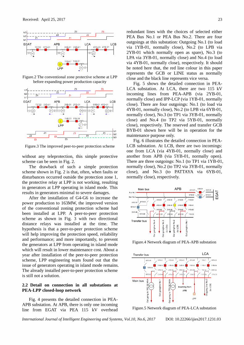
Fig. 5 shows the detailed connection in PEA-
LCA substation. At LCA, there are two 115 kV
incoming lines from PEA-APB (via 2YB-01,
normally close) and IPP-LCP (via 1YB-01, normally
close). There are four outgoings: No.1 (to load via
4YB-01, normally close), No.2 (to LPB via 6YB-01,
normally close), No.3 (to TP1 via 3YB-01, normally
close) and No.4 (to TP2 via 5YB-01, normally
close), respectively. The reserved and transfer GCB
BYB-01 shown here will be in operation for the
maintenance purpose only.
Fig. 6 illustrates the detailed connection in PEA-
LCB substation. At LCB, there are two incomings:
one from LCA (via 4YB-01, normally close) and
another from APB (via 5YB-01, normally open).
There are three outgoings: No.1 (to TP1 via 1YB-01,
normally close), No.2 (to TP2 via 3YB-01, normally
close), and No.3 (to PATTAYA via 6YB-01,
normally close), respectively.
Figure.4 Network diagram of PEA-APB substation
Figure.5 Network diagram of PEA-LCA substation

Received: April 25, 2017 24
International Journal of Intelligent Engineering and Systems, Vol.10, No.6, 2017 DOI: 10.22266/ijies2017.1231.03
Figure.6 Network diagram of PEA-LCB substation
3. Proposed DTT teleprotection scheme
Although we proposed the same name DTT, but
unlike the DTT concept in the protective scheme in
transmission line networks which usually installed
between two substations right next to each other.
What we proposed here is to install the remote
terminal units at every connected bus in this
particular distribution closed-loop network which
results in complete coordination of the distribution
relays regardless of fault locations at any zone
protection. The communication medium in this
particular case is done via PEA’s fiber-optic
network.
3.1 Proposed DTT configuration
To implement DTT technique to this particular
scenario, the Remote terminal units must be
installed at every PEA substation connected to this
loop. All of the available statuses of protection
devices at each substation i.e., the gas circuit
breaker (GCB) and the disconnecting switch (DS)
will be sending out to the logic processor installed at
the LPP power plant. The logic processor will then
determine what to do with all the LPP circuit
breakers and protection devices based on the status
acquiring from other protection devices from other
substations in this particular loop. More details on
how the logic processor works will be explained in
section 3.2. The main goal of this DTT concept is to
protect the LPP’s generators from operating in
Islanding mode when there are some faults occurred
in any other location for this power system network;
especially, when the sources of power from PEA is
disconnected from the system. Another positive
point is that when implementing this DTT concept
to the system, we expect faster operating time in any
protection scenario.
Fig. 7 illustrates the schematic diagram of the
proposed DTT technique with Mirrored bits®
protocol protection scheme. In this paper, we apply
the SEL-2505/SEL-2506 as remote terminal units at
Figure.7 The proposed single line diagram of a DTT
technique with mirror bit protocol protection scheme
Figure.8 The simplified single line diagram of the
proposed DTT configuration
each connected substation and the SEL-2100 as a
logic processor at LPP station. All of the
telecommunication cables were connected via PEA
fiber-optic network. Fig. 8 presents the simplified
version of the proposed DTT teleprotection scheme
as described in Fig. 7.
3.2 Proposed DTT logic diagram
The logic diagram of the proposed DTT
configuration for this particular case in LPP power
plant is illustrated in Fig. 9. The logic diagram for
this system must be redesign rather than the
conventional DTT one.
Logic diagram shown in Fig. 9 was designed
based on the concept of the DTT technique which
has main purpose to protect the Generators of LPP
power plant from operating in Island mode when
any kind of fault occurred in PEA closed-loop
network. The second goal is to assure the speed of
GCB tripping time to be faster than the conventional
peer-to-peer protection scheme to also protect the
Generators of LP power plant from damages in
Islanding mode. Presented logic diagram here

Received: April 25, 2017 25
International Journal of Intelligent Engineering and Systems, Vol.10, No.6, 2017 DOI: 10.22266/ijies2017.1231.03
Figure.9 Logic diagram for DTT configuration
covers mostly the main and critical criteria for trip
signal to open the GCB 1YB-01 (at LCA).
For example, the GCB 1YB-01 must trip
instantaneously while DTT is in place when fault
occurred at the transmission line level or PEA
incoming Bus. Another example is that if there is a
fault occurred at 2YB-01 (LCA) or 3YB-01 (APB),
the DTT protection scheme must recheck to see
whether or not the GCB 6YB-01(LCA) or 4YB-
01(LCB) is opened. If the above condition is true,
The DTT logic controller must send out the trip
signal to open the GCB 1YB-01 simultaneously.
3.3 Proposed DTT circuit breaker details
Fig. 10, Fig. 11 and Fig. 12 illustrate the single
line diagram including the incoming and outgoing
details of each substation connected to this PEA
loop (APB, LCA, LCB, respectively).
Fig. 10(a) represents the modified single line
diagram of APB substation to meet up with the
specification of the proposed DTT technique. Fig.
10(b) also illustrates the logic algorithm of the trip
matrix and trip circuit at APB substation.
This modification is done by redoing the logic
function in according to DTT technique criteria
using the acquired signals from GCB (Gas circuit
breaker) and DS (Disconnecting switch) auxiliary
contacts. It is then sending out the trip signal to
open/close the GCB 1YB-01 (to LCA).
At OUT1 and OUT2 terminals, the trip signals
will be sending out to open GCB 1YB-01 (LCA)
when DS 2YS-03 (LCA) or GCB 2YB-01 (APB)
opened. Another case to send out the trip signals is
when the transfer bus function is in use meaning that
the GCB BYB-01 or GCB 6YB-01 are opened, see
also Fig. 10(b).
(a)
(b)
Figure.10 Single diagram of the APB substation: (a) DTT
function and (b) Trip matrix and Trip circuit
At OUT3 and OUT4 terminals, the trip signals
will be sending out to open GCB 1YB-01 (LCA)
when DS 3YS-03 (APB) or GCB 3YB-01 (APB)
opened. Another case to send out the trip signals is
when the transfer bus function is in use meaning that
the GCB BYB-01 or GCB 5YB-01 are opened, see
also Fig. 10 (b).
Fig. 11 represents the modified single line
diagram, the logic algorithm of the trip matrix and
trip circuit at LCA substation. This modification
with the same concept as mentioned in Fig. 10. The
details are as follows:
At OUT1 and OUT2 terminals, the trip signals
will be sending out to open GCB 1YB-01 (LCA)
when DS 1YC-03 (APB) or GCB 1YB-01 (APB)
opened. Another case to send out the trip signals is
when the transfer bus function is in use meaning that
the GCB BYB-01 is opened; see also Fig. 11(b).
At OUT3 and OUT4 terminals, the trip signals
will be sending out to open GCB 1YB-01 (LCA)
when DS 2YS-03 (APB) or GCB 2YB-01 (APB)
opened. Another case to send out the trip signals is
when the transfer bus function is in use meaning that
the GCB BYB-01 is opened; see also Fig. 11(b).
At OUT5 and OUT6 terminals, the trip signals

Received: April 25, 2017 26
International Journal of Intelligent Engineering and Systems, Vol.10, No.6, 2017 DOI: 10.22266/ijies2017.1231.03
(a)
(b)
Figure.11 Single diagram of the LCA substation: (a) DTT
function and (b) Trip matrix and trip circuit
will be sending out to open GCB 1YB-01 (LCA)
when DS 6YS-03 (APB) or GCB 6YB-01 (APB)
opened; see also Fig. 11(b).
Additional function at this substation, at Out7
and Out8, is to send out the trip signals to open GCB
1YB-01 (LCA) when DS 4YS-03 (LCA) or GCB
4YB-01 opened or when the transfer bus GCB
BYB-01 is in functioned.
Fig. 12(a) represents the modified single line
diagram, the logic algorithm of the trip matrix and
trip circuit at LCB substation. The details of the trip
matrix and trip circuits are as follows:
At OUT1 and OUT2 terminals, the trip signals
will be sending out to open GCB 1YB-01 (LCA)
when DS 5YS-03 (LCB) or GCB 5YB-01 (APB)
opened. Another case to send out the trip signals is
when the transfer bus function is in use meaning that
the GCB BYB-01 is opened; see also Fig. 12(b).
At OUT3 and OUT4 terminals, the trip signals
will be sending out to open GCB 1YB-01 (LCA)
when DS 4YS-03 (LCB) or GCB 4YB-01 (APB)
opened. Another case to send out the trip signals is
(a)
(b)
Figure.12 Single diagram of the LCB substation: (a)
DTT function and (b) Trip matrix and trip circuit
when the transfer bus function is in use meaning that
the GCB BYB-01 is opened; see also Fig. 12(b).
Additional function at this substation, at Out5
and Out6, is to send out the trip signals to open GCB
1YB-01 (LCA) when DS 2YS-03 (LCB) or GCB
2YB-01 opened or when the transfer bus GCB
BYB-01 is in functioned.
4. The proposed DTT test results
In order to verify the proposed protection scheme
validity and reliability, the commissioning test after
installation is mandatory (this process is sometimes
called FAT test). The commissioning test procedures
utilize the hardware test tools (OMICRON CMC-356
universal relay test equipment) and also the special
simulation software. The commissioning test was
done under various fault conditions.
4.1 DTT versus Peer-to-Peer logic test results
Fig.13 illustrates system configuration for the
FAT/commissioning test set up of teleprotection
cabinets. This was done by simulating the connection
between two teleprotection cabinets at both ends
(APB and LCA) then connecting with actual devices
in the simulation. The DTT with Mirrored bits®

Received: April 25, 2017 27
International Journal of Intelligent Engineering and Systems, Vol.10, No.6, 2017 DOI: 10.22266/ijies2017.1231.03
Figure.13 System configuration of RTU cabinet for the
faults simulation and commissioning tests
F1: Fault at LCB Bus
F2: Fault at Line between LCA and LCB
F3: Fault at LCA Bus F4: Fault at Line between LCA and LP
F5: Fault at LP Bus
F6: Fault at Line between LCA and APB F7: Fault at APB Bus
F8: Fault at Line between APB and LCB
Figure.14 Simulation fault locations for proposed DTT
protocol signals are applied to relay protections at
each side. The injected voltage and current to the
relay was created by a test tool (OMICRON CMC-
356). The DTT signal is also simulated by copper
wires via Digital input/output (DI/DO) of
teleprotection cabinets. The protective relay
operating results will send out the signal to the logic
processor via remote I/O terminal. The operating
time of all signals are measured by this procedure.
Fig. 14 presents a variety of possible fault
locations at each of PEA closed-loop substations,
Buses and Lines used in the commissioning test
configurations.
The experimental results for the commissioning
test of the DTT teleprotection functions compared to
Table 1. Commissioning test results for difference faults
simulation with DTT protection scheme installation
(115 kV incoming from Main Bus 1)
Fault EGAT
Status
Status mode
(LP)
Peer-
to-Peer
(LP)
DTT
(LP)
F1 In service Normal No trip No trip
F2 In service Normal No trip No trip
F3 In service Island No trip Trip
F4 In service Island Trip Trip
F5 In service Island Trip Trip
F6 In service Island No trip Trip
F7 Out of
service Island No trip Trip
F8 N/A N/A N/A N/A
Table 2. Commissioning test results for difference faults
simulation with DTT protection scheme installation (115 kV incoming from Main Bus 2)
Fault EGAT
Status
Status mode
(LP)
Peer-
to-Peer
(LP)
DTT
(LP)
F1 In service Island No trip Trip
F2 In service Island No trip Trip
F3 In service Island No trip Trip
F4 In service Island Trip Trip
F5 In service Island Trip Trip
F6 N/A N/A N/A N/A
F7 Out of
service Island No trip Trip
F8 In service Island No trip Trip
(a) (b)
(c) (d)
Figure.15 Actual system configuration of RTU cabinet
and remote I/O units for the proposed DTT scheme: (a)
Remote I/O unit (SEL-2505), (b) Remote I/O at LCA, (c)
Remote I/O at LCA and (d) Logic processor at LPP

Received: April 25, 2017 28
International Journal of Intelligent Engineering and Systems, Vol.10, No.6, 2017 DOI: 10.22266/ijies2017.1231.03
the traditional and existing peer-to-peer protection scheme are shown in Table 1 and Table 2 and also
can be seen in Fig. 15.
4.2 DTT versus Peer-to-Peer tripping times and
functions test results
In this particular simulation test, the example of
relay setting will be done only on distance relay. By
dividing zone protection into four zones, distance
relay protection settings at both APB and LPP
terminals will be illustrated as follows:
Zone 1: setting at 80% of transmission line with
instantaneous trip time
Zone 2: setting at 100% + 20% of transmission
line with 300 ms. trip time
Zone 3: setting reverse with 300 ms trip time
Zone 4: setting forward with 300 ms trip time
In this simulation test, fault currents and
voltages (using relay tester) will be fed into distance
relay protection in a particular zone at each
substation: APB and LPP, Fig. 11. The simulation
test results when injecting fault to each location can
be seen from Table 3 (fault at APB) and Table 4
(Fault at LPP). The distance relay trip time of the
Table 3. Validation and trip time comparisons test
results for distance relay when fault occurred at the power
sources substation APB (at the PEA Line 1)
Faults
Traditional
Peer-to-Peer
(Only distance relay)
DTT
Technique
at LPP
Time
set
(ms)
at APB
(ms)
at
LPP
(ms)
Time
set
(ms)
Found
(ms)
Zone 1 Inst 33.46 Seen as
back
up
protect-
tion
Inst 34.52
Zone 2 300 289.45 300 299.84
Zone 3 300 299.35 300 300.45
Zone 4 600 589.50 600 600.62
Table 4. Validation and trip time comparisons test results
for distance relay when fault occurred at the LPP
power plant
Faults
Traditional
Peer-to-Peer
(Only distance relay)
DTT
Technique
at LPP
Time
set
(ms)
at APB
(ms)
at
LPP
(ms)
Time
set
(ms)
Found
(ms)
Zone 1 Inst Seen as
back up
protect-
tion
37.21 Inst 38.05
Zone 2 300 295.41 300 296.03
Zone 3 300 285.68 300 286.32
Zone 4 600 588.40 600 589.67
conventional protection system will be directly
measured at the fault location. The trip time of the
DTT technique will be measured at the LPP only.
It can clearly be seen from the simulation test
results shown in Table 3 and Table 4 that when there
is any fault occurred out of Zone 1 protection, the
conventional peer-to-peer protection scheme either
detects the fault too slow or cannot detect the fault at
all, resulting in Islanding mode operation of LPP’s
generators and may cause damages.
On the other hand, the proposed DTT technique
with Mirrored Bits® protocol is able to sense any
fault from remote location almost simultaneously
even if when the fault is out of Zone 1 protection.
Consequently, the GCB at LPP is able to open on
time to prevent any damage from generators
operating on Islanding mode. Also, the speed of
operation with DTT protection scheme is excellent.
5. Conclusions
It can be clearly seen from the commissioning
test results that the newly proposed DTT technique
for this particular closed-loop distribution network
works flawlessly. The proposed DTT technique
completely covers in preventing generators at LPP
from operating in islanding mode while the
conventional peer-to-peer technique cannot in many
fault circumstances. The simulation results also
show that the proposed DTT time of operation is
almost instantaneous regardless of fault locations.
These result in better stability, speed and security of
the distribution network. The same concept as
presented in this paper would highly be beneficial
for other similar power system protection with DGs
in Thailand or other countries in the near future to
come.
ACKNOWLEDGMENTS
The authors would like to thank Lamchabang
Power, Thai power center Co., Ltd. and Mr. Athiruk
Aungkum for kindly providing the partial and
important information used in this research. The
authors would also like to thank the ESIRC team
members at KMITL for all of their support in many
ways throughout this research. And lastly, the first
author would like to give a special thanks to both of
the Electrical engineering departments at KMITL
and MUT for part of the financial supports.
References
[1] C. Chompoo-inwai, P. Fuangfoo, and W. Lee,
“Transmission Congestion Management during
Transition Period of Electricity Deregulation in

Received: April 25, 2017 29
International Journal of Intelligent Engineering and Systems, Vol.10, No.6, 2017 DOI: 10.22266/ijies2017.1231.03
Thailand”, IEEE Transaction on Industrial
Application, Vol.43, No.6, pp.1483-1490, 2007.
[2] D. Fischer and R. Madge, “Digital Tele-
protection Units: A Technology Overview”,
IEEE Transactions on Power Delivery, Vol.7,
No.4, pp.1769-1774, 1992.
[3] International Electrotechnical Commission, IEC
60834-1 Standard: Teleprotection Equipment of
Power System Performance and Testing - Part 1:
Command System, Ed. 2.0, 1999.
[4] International Electrotechnical Commission, IEC
60834-2 Standard: Performance and Testing of
Teleprotection Equipment of Power Systems -
Part 2: Analogue Comparison Systems, 1993.
[5] E. Schweitzer, K. Behrendt, T. Lee, and D. A.
Tziouvaras, “Digital Communications for Power
System Protection: Security, Availability, and
Speed”, In: Proc. of 2001 7th International
Conference on Development in Power System
Protection, Amsterdam, Netherland, pp.94-97,
2001.
[6] E. Schweitzer, D. Finney, and M. V. Mynam,
“Applying Radio Communication in
Distribution Generation Teleprotection
Schemes”, In: Proc. of 65th Annual Conference
for Protective Relay Engineers, College Station,
TX, pp.310-320, 2012.
[7] J. Jager, M. Ramold, and S. Li, “Adaptive
Protection Co-ordination Methods Concerning A
Dedicated Operation of Large IPP Unit
Connected to The Transmission Grid”, In: Proc.
of IEEE International Conference on Power
System Technology, Changing, China, pp.1-4,
2006.
[8] A. Luiz and P. Oliveira, “The Use of Real Time
Digital Simulation for Performance Analysis of
Distance Protection and Differential Protection
in Short Transmission Lines”, In: Proc. of
CIRED 20th International Conference on
Electricity Distribution, Prague, Czech &
Republic, pp.8-11, 2009.
[9] M. Khodadad and S. Shahrtash, “Guideline for
Selecting Teleprotection Schemes for TOFFs-
Case Study: Iran Grid”, In: IEEE 10th
International Conference on Environment and
Electrical Engineering, Rome, Italy, pp.1-5,
2011
[10] E. Schweitzer, D. Finney, and M. Mynam,
“Applying Radio Communication in
Distribution Generation Teleprotection
Schemes”, In: IEEE Annual Conference for
Protective Relay Engineers, College Station,
Texas, pp.310-320, 2012.
[11] G. Antonova, E. Colmenares, and I. Jankovic,
“Analysis of Protection Scheme Dependencies
on Communications”, In: IEEE Annual
Conference for Protective Relay Engineers,
College Station, Texas, pp.271-291, 2013.
[12] S. Roesler and R. Lobo, “Proving Viability of
Line Current Differential over Packing Switched
Networks”, In: IEEE 67th Annual Conference for
Protective Relay Engineers, College Station,
Texas, pp.542-551, 2014.
[13] C. Chompoo-inwai, A. Aungkum, N.
Chotiwanaporn, and M. Leelajindakrairerk, “A
New Distributed Generation Protection Scheme
in Thailand Using Direct Transfer Trip (DTT)
Technique and A Mirrored Bit Protocol”,
Journal of International Council on Electrical
Engineering, Vol.5, No.1, pp.34-41, 2015.