A Bulletin 1494V Variable Depth, Flange Operated .......xxx: angles: 42052 this drawing is the...
8
ATTENTION: To prevent electrical shock, disconnect from power source before installing or servicing. Install in suitable enclosure. Keep free from contaminants. Bulletin 1494V Variable Depth, Flange Operated Disconnect Switch Kits for 30 and 60 Amperes (Series A), 100 and 200 Amperes (Series B or Series C Switches) Components Cat No. Description Switch Rating (Amps) 1494V-DS30 1494V-DS60 1494V-DS100 1494V-DS200 30 Amp Switch 60 Amp Switch 100 Amp Switch 200 Amp Switch 1494F-M1 1494F-P1 1494F-S1 5-1/2" Painted Metal Handle 5-1/2" Molded Handle 5-1/2" Stainless Steel Handle 1494V-FS30 1494V-FS60 1494V-FS100 1494V-FS200 30 60 100 200 30 Amp Fuse Block 60 Amp Fuse Block 100 Amp Fuse Block 200 Amp Fuse Block 30 60 100 200 30...200 1494V-RA3 1494V-RA4 Standard Connecting Rod Enclosure Working Depth: 6-3/4" to 9-1/8" Extended Connecting Rod Enclosure Working Depth: 9-1/8" to 21-5/8" 30 60 100 200 (Included) 1494R-N1 1494R-N2 1494R-N3 Lug Connector: Wire Size #14 . . . #8 AWG Lug Connector: Wire Size #14 . . . #4 AWG Lug Connector: Wire Size #14 . . . #1/0 AWG Lug Connector: Wire Size #6 . . . #4/0 AWG 1495-N59 1495-N60 Fuse Cover with Door (only for Right-Hand Installation) 1401-N41 1401-N42 1401-N43 1401-N44 1401-N45 1401-N50 1401-N51 1401-N52 1401-N53 1401-N54 30 30 - 60 60 100-200 100-200 30 30 - 60 60 100-200 Fuse Clip, Class H, 30A - 250V Fuse Clip, Class H,J, 30A - 600V, Class H, 60A-250V Fuse Clip, Class H,J, 60A - 600V Fuse Clip, Class H,J, 100A-250V, 100A-600V Fuse Clip, Class H,J, 200A-250V, 200A-600V Fuse Clip, Class R, 30A - 250V Fuse Clip, Class R, 30A - 600V, 60A-250V Fuse Clip, Class R, 60A - 600V Fuse Clip, Class R, 100A - 250V, 100A-600V Fuse Clip, Class R, 200A-250V, 200A-600V Fuse Cover with Door (only for Right-Hand Installation) 200 100-200 30...200 595-A 595-B (1) N.O. Auxiliary Contact (1) N.C. Auxiliary Contact 30...200 30...100
Transcript of A Bulletin 1494V Variable Depth, Flange Operated .......xxx: angles: 42052 this drawing is the...

1 9
DISCONNECT SWITCH AND ACCESSORYINSTALLATION INSTRUCTION SHEET
1 1004063
42052-064OF
N/A
N/A
N/A
REVISIONAUTHORIZATION
DR.
CHKD.
APPD.
DATE
DATE
DATE
E - DOC
LOCATION: MILWAUKEE, WISCONSIN U.S.A.
B-vertical.ai
DWG.SIZE
SHEET
B
1 2 3 4 5 6 7 8
A
B
C
D
E
F
G
H
REFERENCE
DIMENSIONS APPLY BEFORESURFACE TREATMENT
(DIMENSIONS IN INCHES)TOLERANCES UNLESSOTHERWISE SPECIFIED
.XX:
.XXX:
ANGLES:
42052
THIS DRAWING IS THE PROPERTY OFROCKWELL INTERNATIONAL CORPORATION
OR ITS SUBSIDIARIES AND MAY NOT BE COPIED,USED OR DISCLOSED FOR ANY PURPOSEEXCEPT AS AUTHORIZED IN WRITING BY
ROCKWELL INTERNATIONAL CORPORATION
G. Ushakow 9-10-039-10-03
9-10-03M. JutzJ. Koziczkowski
ATTENTION: To prevent electrical shock, disconnect from power source before installing or servicing. Install in suitable enclosure. Keep free from contaminants.
Bulletin 1494V Variable Depth, Flange Operated Disconnect Switch Kits for 30 and 60 Amperes (Series A), 100 and 200 Amperes (Series B or Series C Switches)
Components Cat No. DescriptionSwitch Rating
(Amps)
1494V-DS301494V-DS601494V-DS1001494V-DS200
30 Amp Switch60 Amp Switch100 Amp Switch200 Amp Switch
1494F-M11494F-P11494F-S1
5-1/2" Painted Metal Handle5-1/2" Molded Handle5-1/2" Stainless Steel Handle
1494V-FS301494V-FS601494V-FS1001494V-FS200
3060
100200
30 Amp Fuse Block60 Amp Fuse Block100 Amp Fuse Block200 Amp Fuse Block
3060
100200
30...200
1494V-RA3
1494V-RA4
Standard Connecting RodEnclosure Working Depth: 6-3/4" to 9-1/8" Extended Connecting RodEnclosure Working Depth: 9-1/8" to 21-5/8"
3060
100200
(Included)1494R-N11494R-N21494R-N3
Lug Connector: Wire Size #14 . . . #8 AWGLug Connector: Wire Size #14 . . . #4 AWGLug Connector: Wire Size #14 . . . #1/0 AWGLug Connector: Wire Size #6 . . . #4/0 AWG
1495-N59
1495-N60
Fuse Cover with Door(only for Right-Hand Installation)
1401-N411401-N42
1401-N431401-N441401-N451401-N501401-N511401-N521401-N531401-N54
3030 - 60
60100-200100-200
3030 - 60
60100-200
Fuse Clip, Class H, 30A - 250VFuse Clip, Class H,J, 30A - 600V,Class H, 60A-250VFuse Clip, Class H,J, 60A - 600VFuse Clip, Class H,J, 100A-250V, 100A-600VFuse Clip, Class H,J, 200A-250V, 200A-600VFuse Clip, Class R, 30A - 250VFuse Clip, Class R, 30A - 600V, 60A-250VFuse Clip, Class R, 60A - 600VFuse Clip, Class R, 100A - 250V, 100A-600VFuse Clip, Class R, 200A-250V, 200A-600V
Fuse Cover with Door(only for Right-Hand Installation)
200
100-200
30...200
595-A
595-B
(1) N.O. Auxiliary Contact
(1) N.C. Auxiliary Contact30...200
30...100
DISCONNECT SWITCH AND ACCESSORYINSTALLATION INSTRUCTION SHEET
1 1004063
42052-064OF
N/A
N/A
N/A
REVISIONAUTHORIZATION
DR.
CHKD.
APPD.
DATE
DATE
DATE
E - DOC
LOCATION: MILWAUKEE, WISCONSIN U.S.A.
B-vertical.ai
DWG.SIZE
SHEET
B
1 2 3 4 5 6 7 8
A
B
C
D
E
F
G
H
REFERENCE
DIMENSIONS APPLY BEFORESURFACE TREATMENT
(DIMENSIONS IN INCHES)TOLERANCES UNLESSOTHERWISE SPECIFIED
.XX:
.XXX:
ANGLES:
42052
THIS DRAWING IS THE PROPERTY OFROCKWELL INTERNATIONAL CORPORATION
OR ITS SUBSIDIARIES AND MAY NOT BE COPIED,USED OR DISCLOSED FOR ANY PURPOSEEXCEPT AS AUTHORIZED IN WRITING BY
ROCKWELL INTERNATIONAL CORPORATION
--------------- ------------------------------
---------------------------------------------
2 9
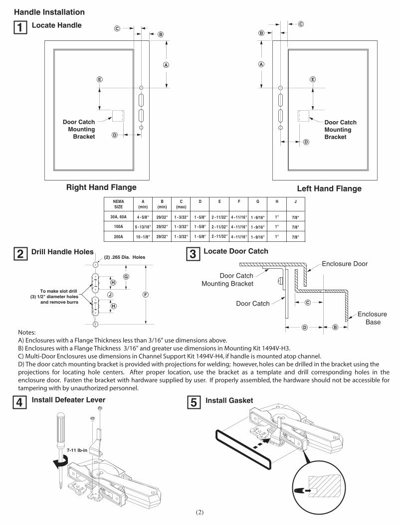
Handle Installation
4
1
3
7-11 lb-in
Door CatchMounting
Bracket
To make slot drill (3) 1/2" diameter holes
and remove burrs
E
D
Door CatchMountingBracket
Locate Handle
Right Hand Flange Left Hand Flange
(2) .265 Dia. HolesDrill Handle Holes
D
BC
C
B
A
C
B
A
E
5
2
F
G
H
J
HDoor Catch
Mounting Bracket
Door Catch
Enclosure Door
D
Enclosure Base
Locate Door Catch
Install Defeater Lever Install Gasket
(2)
Notes:A) Enclosures with a Flange Thickness less than 3/16" use dimensions above.B) Enclosures with a Flange Thickness 3/16" and greater use dimensions in Mounting Kit 1494V-H3.C) Multi-Door Enclosures use dimensions in Channel Support Kit 1494V-H4, if handle is mounted atop channel.D) The door catch mounting bracket is provided with projections for welding; however, holes can be drilled in the bracket using the projections for locating hole centers. After proper location, use the bracket as a template and drill corresponding holes in the enclosure door. Fasten the bracket with hardware supplied by user. If properly assembled, the hardware should not be accessible for tampering with by unauthorized personnel.
1 - 5/8"
D
1 - 5/8"
1 - 5/8"
E
2 - 11/32"
2 - 11/32"
2 - 11/32"
F
4 - 11/16"
4 - 11/16"
4 - 11/16"
G
1 - 9/16"
1 - 9/16"
1 - 9/16"
H
1"
1"
1"
J
7/8"
7/8"
7/8"1 - 3/32"
C(max)
1 - 3/32"
1 - 3/32"
B(min)
29/32"
29/32"
29/32"
A(min)
4 - 5/8"
5 - 13/16"
10 - 1/8"
NEMASIZE
30A, 60A
200A
100A

3 9
DISCONNECT SWITCH AND ACCESSORYINSTALLATION INSTRUCTION SHEET
1 1004063
42052-064OF
N/A
N/A
N/A
REVISIONAUTHORIZATION
DR.
CHKD.
APPD.
DATE
DATE
DATE
E - DOC
LOCATION: MILWAUKEE, WISCONSIN U.S.A.
B-vertical.ai
DWG.SIZE
SHEET
B
1 2 3 4 5 6 7 8
A
B
C
D
E
F
G
H
REFERENCE
DIMENSIONS APPLY BEFORESURFACE TREATMENT
(DIMENSIONS IN INCHES)TOLERANCES UNLESSOTHERWISE SPECIFIED
.XX:
.XXX:
ANGLES:
42052
THIS DRAWING IS THE PROPERTY OFROCKWELL INTERNATIONAL CORPORATION
OR ITS SUBSIDIARIES AND MAY NOT BE COPIED,USED OR DISCLOSED FOR ANY PURPOSEEXCEPT AS AUTHORIZED IN WRITING BY
ROCKWELL INTERNATIONAL CORPORATION
--------------- ------------------------------
---------------------------------------------
RectangularMetal Plate
MovableBlades
Insert the rectangular metal plate provided with the hardware kit into the crossbar end slot on the right-hand side as shown below.
ATTENTION: Do not attempt to change the position of the drive mechanism after removal from the disconnect assembly. Use the rectangular metal plate to rotate the crossbar from the "OFF" position to the full "ON" positiom.
Remove the rectangular metal plate and discard, (not required for switch operation.)Position the drive mechanism assembly as shown below and install the (4) screws.
Rotate the crossbar assembly in a clockwise direction to the "ON" position (blades fully engaged - not visible). (Use any convenient adjustable wrench or pliers to aid in rotating the crossbar & moveable blades.)
With the disconnect switch in the "OFF" position, (blades visible) loosen and remove the (4) screws.Remove the drive mechanism from the right-hand side of the disconnect switch.Save the (4) 1/4-20 pan head screws shown below.
Disconnect Switch Installation
Conversion from Right-Hand Installation to Left-Hand Installation
1
2 3
54
RectangularMetal Plate
Moveable Blades
40-60 lb-in
3 - 29/64" 1 - 27/32" 1 - 31/32" 4 - 21/64" 1" 3 - 15/16" (4) #10-32 2 - 37/64"
AA BB CC DDNEMASIZE
30A, 60A,100A
3 - 53/64" 2 - 63/64" 2 - 23/64" 4 - 59/64" 1 - 7/64" 4 - 23/32" (4) 1/4-20 2 - 61/64"200A
EE FF GG HH
BB BB
CC
DD DDEE EE
FF
AAAAAAAAAAAAAAAAAAAAAAGG AAAAAAAAAAAAAAAAAAAAAACCAAAAAAAAAAAA
FF
LocateDisconnect Switch
Right Hand Flange Left Hand Flange
HH HH
(3)
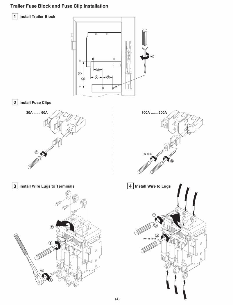
1 Install Trailer Block
2 Install Fuse Clips
30A ....... 60A 100A ....... 200A
3 Install Wire Lugs to Terminals 4 Install Wire to Lugs
4 9
DISCONNECT SWITCH AND ACCESSORYINSTALLATION INSTRUCTION SHEET
1 1004063
42052-064OF
N/A
N/A
N/A
REVISIONAUTHORIZATION
DR.
CHKD.
APPD.
DATE
DATE
DATE
E - DOC
LOCATION: MILWAUKEE, WISCONSIN U.S.A.
B-vertical.ai
DWG.SIZE
SHEET
B
1 2 3 4 5 6 7 8
A
B
C
D
E
F
G
H
REFERENCE
DIMENSIONS APPLY BEFORESURFACE TREATMENT
(DIMENSIONS IN INCHES)TOLERANCES UNLESSOTHERWISE SPECIFIED
.XX:
.XXX:
ANGLES:
42052
THIS DRAWING IS THE PROPERTY OFROCKWELL INTERNATIONAL CORPORATION
OR ITS SUBSIDIARIES AND MAY NOT BE COPIED,USED OR DISCLOSED FOR ANY PURPOSEEXCEPT AS AUTHORIZED IN WRITING BY
ROCKWELL INTERNATIONAL CORPORATION
--------------- ------------------------------
---------------------------------------------
Trailer Fuse Block and Fuse Clip Installation
Y
Z X
Q
R
R
40 lb-in
10 - 15 lb-in
T
S
1
2
2
3
4
V
W
(4)
1

DISCONNECT SWITCH AND ACCESSORYINSTALLATION INSTRUCTION SHEET
1 1004063
42052-064OF
N/A
N/A
N/A
REVISIONAUTHORIZATION
DR.
CHKD.
APPD.
DATE
DATE
DATE
E - DOC
LOCATION: MILWAUKEE, WISCONSIN U.S.A.
B-vertical.ai
DWG.SIZE
SHEET
B
1 2 3 4 5 6 7 8
A
B
C
D
E
F
G
H
REFERENCE
DIMENSIONS APPLY BEFORESURFACE TREATMENT
(DIMENSIONS IN INCHES)TOLERANCES UNLESSOTHERWISE SPECIFIED
.XX:
.XXX:
ANGLES:
42052
THIS DRAWING IS THE PROPERTY OFROCKWELL INTERNATIONAL CORPORATION
OR ITS SUBSIDIARIES AND MAY NOT BE COPIED,USED OR DISCLOSED FOR ANY PURPOSEEXCEPT AS AUTHORIZED IN WRITING BY
ROCKWELL INTERNATIONAL CORPORATION
--------------- ------------------------------
---------------------------------------------
5 9
Trailer Fuse Fuse Fuse Block Fuse Clip Lug to Wire toSwitch Fuse Fuse Block Clip Block Mtg. Screw Mtg. Screw Terminal LugRating Rating Fuse Catalog Catalog V W X Y Z Mounting Torque Torque Torque Torque
TermScrew
(Amps) Amps/Volts Class Number Number inches inches inches inches inches Hole lb-ins. lb-ins. lb-ins. lb-ins.
30A, 250V 1494V-FS30 1401-N41 2-1/4 1-13/16 1-31/32 31/32 9/16
30A, 250V 1494V-FS30 1401-N50 2-1/4 1-13/16 1-31/32 31/32 9/16
30A, 600V 1494V-FS30 1401-N42 2-1/4 1-13/16 1-31/32
30A, 600V 1494V-FS30 1401-N42 2-1/4 1-13/16 1-31/3230
30A, 600V 1494V-FS30 1401-N51 2-1/4 1-13/16 1-31/32 #10-32
60A, 250V 1494V-FS30 1401-N42 2-1/4 1-13/16 1-31/32
60A, 250V 1494V-FS30 1401-N51 2-1/4 1-31/32
60A, 600V 1494V-FS30 1401-N43 2-1/4 1-31/32
60A, 600V 1494V-FS30 1401-N43 2-1/4 1-31/32
60A, 600V 1494V-FS30 1401-N52 2-1/4 1-31/32
60A, 250V 1494V-FS60 2-1/4 1-31/32
60A, 600V 1494V-FS60 2-1/4 1-31/32
60A, 600V 1494V-FS60 2-1/4 1-31/32
60A, 600V 1494V-FS60 2-1/4 1-31/32
1494V-FS60 2-1/4 1-31/32#10-32
1494V-FS60 2-1/4 1-31/32 1-21/64
60A, 600V 1494V-FS60 2-1/4 1-31/32 1-21/6460
60A, 600V
60A, 600V
60A, 600V
1494V-FS60 2-1/4 1-31/32 3-53/64
60A, 600V 1494V-FS60 2-1/4 1-31/32 11/16
100A, 600V 2-1/4 1-31/32 5-13/16 #10-32
100A, 600V 1494V-FS60 2-1/4 1-31/32 5-13/16
60A, 600V 1494V-FS100 1401-N43 2-1/8 1-31/32 6-17/64
#10-32
60A, 600V 1494V-FS100 1401-N52 2-1/8 1-11/16 1-31/32 6-17/64
#10-32
100
100A, 600V 1494V-FS200 1401-N44 1-41/64 1-1/4 2-23/64
100A, 600V 1494V-FS200 1401-N44 1-41/64 1-1/4 2-23/64
100A, 600V 1494V-FS200 1401-N53 1-41/64 1-1/4 2-23/64
200A, 250V 1494V-FS200 1401-N45 1-41/64 1-1/4 2-23/64
200 1/4-20
200A, 600V 1494V-FS200 1401-N45 1-41/64 1-1/4 2-23/64
(5)
H
J
R
H
J
H
R
8-35/64
5-19/64
8-35/64
7-27/64
6-3/64
H
R
H
R
H
J
1401-N41
1401-N50
1401-N42
1401-N42
1401-N51
1401-N42
1401-N51
1401-N43
1401-N43
1401-N44
1401-N53
6-5/8
6-7/32
6-5/8
1-13/16
1-13/16
1-13/16
1-13/16
1-13/16
1-13/16
1-13/16
1-13/16
1-13/16
1-13/16
1-13/16
1-13/16
1-13/16
1-13/16
1-13/16
1-11/16
1-47/64
1-47/64
4-15/64
1-3/32
6-7/32
3-47/64
31/32
3-47/64
1-47/64
1-47/64
4-15/64
1-3/32
4-15/64
31/32
31/32
3-47/64
31/32
3-47/64
3-21/64
9/16
3-21/64
1-11/32
1-11/32
3-27/32
23/32
3-27/32
9/16
9/16
3-11/32
1-11/32
3-11/32
6-53/64
3-37/64
6-53/64
5-43/64
4-21/64
H
R
H
J
30A, 600V 1494V-FS30 1401-N42 2-1/4 1-13/16 1-31/32 31/32 9/16J
R
H
R
H
J
R
H
R
H
J
R
3030
3030
20
30
2030
30
30
40
#5/16/2415090
20 #3/8-24275175
#1/4-284550
#10-322030
100A, 600V 1494V-FS60 2-1/4 1-31/32 2-9/16J 1401-N44 2-31/32 1-13/16
100A, 250V 1494V-FS60 2-1/4 1-31/32 3-27/32R 1401-N53 1-13/16 4-1/4
1494V-FS60
60A, 600V 1494V-FS60 2-1/4 1-31/32 3-53/64R 1401-N52 1-13/16 4-15/64
1494V-FS60 2-1/4 1-31/32 3-27/32100A, 250V H 1401-N44 1-13/16 4-1/4
60A, 600V
**
**
* FUSE BOLTS DIRECTLY TO THE SWITCH AND FUSE BLOCK TERMINALS**FUSE ADAPTER KIT CATALOG NUMBER 1401-N170 REQUIRED.
** 1494V-FS100 1401-N43 2-1/8 1-11/16 1-31/32 4-63/64 J 5-3/8
100A, 250V 1494V-FS100 1401-N44 2-1/8 1-11/16 1-31/32H 4-5/8 4-15/64
100A, 250V 1494V-FS100 1401-N53 2-1/8 1-11/16 1-31/32R 4-5/8 4-15/64
100A, 250V 1494V-FS100 1401-N44 2-1/8 1-11/16 1-31/32H 6-5/8 6-15/64
100A, 600V 1494V-FS100 1401-N44 2-1/8 1-11/16 1-31/32J 3-3/8 2-63/64
100A, 600V 1494V-FS100 1401-N53 2-1/8 1-11/16 1-31/32R 6-5/8 6-15/64
400A, 600V 1494V-FS200 1401-N46 1-41/64 1-1/4 2-23/64 1/4-20J 8-17/32 6-13/64 17540
200A, 600V 1494V-FS200 1401-N54
*
*
1-41/64 1-1/4 2-23/64R 9-59/64 8-13/64
200A, 600V 1494V-FS200 1401-N45 1-41/64 1-1/4 2-23/64H 9-59/64 8-13/64
200A, 250V 1494V-FS200 1401-N54 1-41/64 1-1/4 2-23/64R 7-27/64 5-43/64
200A, 600V 1494V-FS100 1401-N45 7/16 1-11/16 1-31/32J 4-1/8 3-47/64 #10-32 9030

DISCONNECT SWITCH AND ACCESSORYINSTALLATION INSTRUCTION SHEET
1 1004063
42052-064OF
N/A
N/A
N/A
REVISIONAUTHORIZATION
DR.
CHKD.
APPD.
DATE
DATE
DATE
E - DOC
LOCATION: MILWAUKEE, WISCONSIN U.S.A.
B-vertical.ai
DWG.SIZE
SHEET
B
1 2 3 4 5 6 7 8
A
B
C
D
E
F
G
H
REFERENCE
DIMENSIONS APPLY BEFORESURFACE TREATMENT
(DIMENSIONS IN INCHES)TOLERANCES UNLESSOTHERWISE SPECIFIED
.XX:
.XXX:
ANGLES:
42052
THIS DRAWING IS THE PROPERTY OFROCKWELL INTERNATIONAL CORPORATION
OR ITS SUBSIDIARIES AND MAY NOT BE COPIED,USED OR DISCLOSED FOR ANY PURPOSEEXCEPT AS AUTHORIZED IN WRITING BY
ROCKWELL INTERNATIONAL CORPORATION
--------------- ------------------------------
---------------------------------------------
6 9
1
2 3
ConnectingRod Min. Max.
"N"
Standard
Extended
Catalog Number
1494V-RA3
1494V-RA4
6-3/4" 9-1/8"
9-1/8" 21-5/8"
Connecting Rod Installation
Right Hand Operation
Connecting Rod Adjustment Procedure
N
EnclosureWorking Depth
(Flange toMounting Plate)
N - 3"
Front
Install connecting rod in mechanism and thread in clockwise (12) full turns
Place the disconnect handle in the "OFF" position. Insert the ears of rod into the primary link of the handle and install the hitch pin as shown below
4 5"ON" Position
a) Move disconnect handle to the "ON" position.
b) If switch does not fully close, return handle to "OFF" position.
c) Remove hitch pin and disengage the connectiong rod from the primary link.
d) Turn connecting rod counter-clockwise (1) full turn.
e) Re-engage connecting rod in primary link of handle, insert hitch pin and re-test
f) Repeat 4a - 4e as necessary.
"OFF" Position
g) Move disconnect handle to the "OFF" position.
h) If switch does not fully open, return handle to "ON" position.
j) Remove hitch pin and disengage the connectiong rod from the primary link.
k) Turn connecting rod clockwise (1) full turn.
l) Re-engage connecting rod in primary link of handle, insert hitch pin and re-test
m) Repeat 5g - 5l as necessary.
(6)

1004063
AlignArrows
Auxiliary Contact Installation
Click
DISCONNECT SWITCH AND ACCESSORYINSTALLATION INSTRUCTION SHEET
1
42052-064OF
N/A
N/A
N/A
REVISIONAUTHORIZATION
DR.
CHKD.
APPD.
DATE
DATE
DATE
E - DOC
LOCATION: MILWAUKEE, WISCONSIN U.S.A.
B-vertical.ai
DWG.SIZE
SHEET
B
1 2 3 4 5 6 7 8
A
B
C
D
E
F
G
H
REFERENCE
DIMENSIONS APPLY BEFORESURFACE TREATMENT
(DIMENSIONS IN INCHES)TOLERANCES UNLESSOTHERWISE SPECIFIED
.XX:
.XXX:
ANGLES:
42052
THIS DRAWING IS THE PROPERTY OFROCKWELL INTERNATIONAL CORPORATION
OR ITS SUBSIDIARIES AND MAY NOT BE COPIED,USED OR DISCLOSED FOR ANY PURPOSEEXCEPT AS AUTHORIZED IN WRITING BY
ROCKWELL INTERNATIONAL CORPORATION
--------------- ------------------------------
---------------------------------------------
7 9
6
Left Hand Operation
7
1 2
Place the disconnect handle in the "ON" position. Insert the ears of rod into the primary link of the handle and install the hitch pin as shown below.
Install connecting rod in mechanism and thread in clockwise (9) full turns.
(7)
Connecting Rod Adjustment Procedure
8 9"ON" Position
a) Move disconnect handle to the "ON" position.
b) If switch does not fully close, return handle to "OFF" position.
c) Remove hitch pin and disengage the connectiong rod from the primary link.
d) Turn connecting rod counter-clockwise (1) full turn.
e) Re-engage connecting rod in primary link of handle, insert hitch pin and re-test
f) Repeat 4a - 4e as necessary.
"OFF" Position
g) Move disconnect handle to the "OFF" position.
h) If switch does not fully open, return handle to "ON" position.
j) Remove hitch pin and disengage the connectiong rod from the primary link.
k) Turn connecting rod clockwise (1) full turn.
l) Re-engage connecting rod in primary link of handle, insert hitch pin and re-test
m) Repeat 5g - 5l as necessary.
Important: Before installing auxiliary contact, disconnect switch must be in "Off" position.

DISCONNECT SWITCH AND ACCESSORYINSTALLATION INSTRUCTION SHEET
1 1004063
42052-064OF
N/A
N/A
N/A
REVISIONAUTHORIZATION
DR.
CHKD.
APPD.
DATE
DATE
DATE
E - DOC
LOCATION: MILWAUKEE, WISCONSIN U.S.A.
B-vertical.ai
DWG.SIZE
SHEET
B
1 2 3 4 5 6 7 8
A
B
C
D
E
F
G
H
REFERENCE
DIMENSIONS APPLY BEFORESURFACE TREATMENT
(DIMENSIONS IN INCHES)TOLERANCES UNLESSOTHERWISE SPECIFIED
.XX:
.XXX:
ANGLES:
42052
THIS DRAWING IS THE PROPERTY OFROCKWELL INTERNATIONAL CORPORATION
OR ITS SUBSIDIARIES AND MAY NOT BE COPIED,USED OR DISCLOSED FOR ANY PURPOSEEXCEPT AS AUTHORIZED IN WRITING BY
ROCKWELL INTERNATIONAL CORPORATION
--------------- ------------------------------
---------------------------------------------
8 9
Fuse Cover Installation
30 A ... 100 A Non-Fused30 A, 250 V, Class H, R Fuses30 A, 600 V, Class J Fuses60 A, 250 V, Class H, R Fuses60 A, 600 V, Class J Fuses100 A, 600 V, Class J Fuses
100 A, 600 V, Class H, R Fuses
30 A, 600 V, Class H, R Fuses60 A, 600 V, Class H, R Fuses100 A, 250 V, Class H, R Fuses200 A, 600 V, Class J Fuses
1
1
2
2
42052-064-01 (1)Printed in U.S.A.
200 A
30 A ... 100 A
2
2
200 A Non-Fused100 A, 250 V, Class H, R Fuses100 A, 600 V, Class H, J, R Fuses200 A, 250 V, Class H, R Fuses200 A, 600 V, Class H, J, R Fuses400 A, 600 V, Class J Fuses

![SHCJ ARCHIVES MAYFIELD [copied from the original]](https://static.fdocuments.us/doc/165x107/62948e6e24ed5671cd4a9749/shcj-archives-mayfield-copied-from-the-original.jpg)