A biologically inspired, flapping-wing, hybrid aerial ... · flapping-wing flight (13) and...
12
BIOMIMETICS Copyright © 2017 The Authors, some rights reserved; exclusive licensee American Association for the Advancement of Science. No claim to original U.S. Government Works A biologically inspired, flapping-wing, hybrid aerial-aquatic microrobot Yufeng Chen, 1,2 * Hongqiang Wang, 1,2 E. Farrell Helbling, 1,2 Noah T. Jafferis, 1,2 Raphael Zufferey, 3 Aaron Ong, 1,2,4 Kevin Ma, 1,2 Nicholas Gravish, 4 Pakpong Chirarattananon, 5 Mirko Kovac, 3 Robert J. Wood 1,2 * From millimeter-scale insects to meter-scale vertebrates, several animal species exhibit multimodal locomotive capabilities in aerial and aquatic environments. To develop robots capable of hybrid aerial and aquatic locomotion, we require versatile propulsive strategies that reconcile the different physical constraints of airborne and aquatic environments. Furthermore, transitioning between aerial and aquatic environments poses substantial challenges at the scale of microrobots, where interfacial surface tension can be substantial relative to the weight and forces produced by the animal/robot. We report the design and operation of an insect-scale robot capable of flying, swimming, and transitioning between air and water. This 175-milligram robot uses a multimodal flapping strategy to efficiently locomote in both fluids. Once the robot swims to the water surface, lightweight electrolytic plates produce oxyhydrogen from the surrounding water that is collected by a buoyancy chamber. Increased buoyancy force from this electrochemical reaction gradually pushes the wings out of the water while the robot maintains upright stability by exploiting surface tension. A sparker ignites the oxyhydrogen, and the robot impulsively takes off from the water surface. This work analyzes the dynamics of flapping locomotion in an aquatic environment, identifies the challenges and benefits of surface tension effects on microrobots, and further develops a suite of new mesoscale devices that culminate in a hybrid, aerial-aquatic microrobot. INTRODUCTION A few animal species (1–5) demonstrate the remarkable capability of hybrid aerial-aquatic locomotion to search for food sources, chase prey, and evade predators. Hybrid aerial-aquatic robots capable of traversing complex multiphase environments will have a wide range of applica- tions, such as environmental exploration and search and rescue missions (6). Owing to smaller physical size and weight, microrobots are advantageous for navigating within confined and cluttered environ- ments. Because of diminishing inertial forces at the millimeter scale, microrobots are more resilient to impact events such as a crash landing on water or collision with obstacles (7 ). Compared with conventional robots, microrobots can easily land on vertical surfaces (8) or even perch on overhangs (9) by exploiting surface effects. Despite these functional advantages, hybrid aerial-aquatic microrobots face unique fabrication challenges and physical constraints. A hybrid aerial-aquatic microrobot must solve two key problems: (i) multiphase propulsion for air and water and (ii) overcoming surface tension for water entry and exit. The large density difference between air and water imposes conflicting criteria for robot locomotion and structural design in these two environments. A number of robotic plat- forms, such as fixed wing (10), foldable wing (11), and rotorcraft vehi- cles (12), have been developed to explore multiphase locomotion. Although there are no fixed wing or foldable wing designs that are fully operational in aerial and aquatic environments, a recent study adapted a rotorcraft to aquatic locomotion and further demonstrated air-to-water and water-to-air transition (12). However, a rotorcraft design cannot be easily adapted by a microrobot because of fabrication difficulty and sur- face tension effects, which can exceed robot weight by over 10 times. In addition, the physics of scaling indicates that conventional brushless motors are not feasible on the order of milligrams. In the past decade, there has been a growing interest in studying flapping-wing flight (13) and developing flapping-wing robots (14). Aerial flapping-wing propulsion generates large lift forces by using unsteady aerodynamic mechanisms such as rotational circulation (15) and periodic vortex shedding (13, 16). Recently, flapping aquatic loco- motion was observed in zooplankton (17) in a similar Reynolds number regime (~100). A previous work (18) compared the fluid mechanical similarities of a single flapping wing in air and in water and demon- strated aerial-aquatic locomotion on an existing micro aerial vehicle. However, the work did not identify the trade-off between aerial and aquatic flapping, and consequently, the robot suffered short actuator lifetime because of stress induced by a nonoptimal choice of operation frequency. Furthermore, surface tension far exceeds a robot’s weight and its maximum lift capability at the milligram and millimeter scales. Hence, transitioning into or out of water requires novel mechanisms to overcome this effect. However, any additional mechanisms must satisfy the micro- robot ’ s subgram payload capability. This design challenge requires fabri- cation of lightweight, energy-efficient, and multifunctional components for locomotion and water-to-air transition. Water-to-air transition with a microrobot has not been previously demonstrated because of the diffi- culty in developing an impulsive mechanism that weighs less than 50 mg and operates underwater. A recent work developed a single-use chemical reaction–based thruster (11) that weighs 2.6 g, which is too heavy to be incorporated onto insect-scale robots. Another study used a shape memory alloy (19) actuator to impulsively push off the water surface for the takeoff of a 68-mg robot. However, this device cannot demonstrate repeatable takeoff, and it cannot be adapted to vehicles that are sub- merged in water. 1 John A. Paulson School of Engineering and Applied Sciences, Harvard University, Cambridge, MA 02138, USA. 2 Wyss Institute for Biologically Inspired Engineering, Harvard University, Cambridge, MA 02138, USA. 3 Aerial Robotics Laboratory, De- partment of Aeronautics, Imperial College London, London, UK. 4 Department of Mechanical and Aerospace Engineering, University of California, San Diego, San Diego, CA 92093, USA. 5 Department of Mechanical and Biomedical Engineering, City University of Hong Kong, Hong Kong SAR, China. *Corresponding author. Email: [email protected] (R.J.W.); yufengchen@ seas.harvard.edu (Y.C.) SCIENCE ROBOTICS | RESEARCH ARTICLE Chen et al., Sci. Robot. 2, eaao5619 (2017) 25 October 2017 1 of 11 by guest on January 18, 2020 http://robotics.sciencemag.org/ Downloaded from
Transcript of A biologically inspired, flapping-wing, hybrid aerial ... · flapping-wing flight (13) and...

SC I ENCE ROBOT I C S | R E S EARCH ART I C L E
B IOM IMET I CS
1John A. Paulson School of Engineering and Applied Sciences, Harvard University,Cambridge, MA 02138, USA. 2Wyss Institute for Biologically Inspired Engineering,Harvard University, Cambridge, MA 02138, USA. 3Aerial Robotics Laboratory, De-partment of Aeronautics, Imperial College London, London, UK. 4Department ofMechanical and Aerospace Engineering, University of California, San Diego, SanDiego, CA 92093, USA. 5Department of Mechanical and Biomedical Engineering,City University of Hong Kong, Hong Kong SAR, China.*Corresponding author. Email: [email protected] (R.J.W.); [email protected] (Y.C.)
Chen et al., Sci. Robot. 2, eaao5619 (2017) 25 October 2017
Copyright © 2017
The Authors, some
rights reserved;
exclusive licensee
American Association
for the Advancement
of Science. No claim
to original U.S.
Government Works
http:/D
ownloaded from
A biologically inspired, flapping-wing, hybridaerial-aquatic microrobotYufeng Chen,1,2* Hongqiang Wang,1,2 E. Farrell Helbling,1,2 Noah T. Jafferis,1,2 Raphael Zufferey,3
Aaron Ong,1,2,4 Kevin Ma,1,2 Nicholas Gravish,4 Pakpong Chirarattananon,5
Mirko Kovac,3 Robert J. Wood1,2*
From millimeter-scale insects to meter-scale vertebrates, several animal species exhibit multimodal locomotivecapabilities in aerial and aquatic environments. To develop robots capable of hybrid aerial and aquatic locomotion,we require versatile propulsive strategies that reconcile the different physical constraints of airborne and aquaticenvironments. Furthermore, transitioning between aerial and aquatic environments poses substantial challenges atthe scale of microrobots, where interfacial surface tension can be substantial relative to the weight and forcesproduced by the animal/robot. We report the design and operation of an insect-scale robot capable of flying,swimming, and transitioning between air and water. This 175-milligram robot uses a multimodal flapping strategyto efficiently locomote in both fluids. Once the robot swims to the water surface, lightweight electrolytic platesproduce oxyhydrogen from the surrounding water that is collected by a buoyancy chamber. Increased buoyancyforce from this electrochemical reaction gradually pushes the wings out of the water while the robot maintainsupright stability by exploiting surface tension. A sparker ignites the oxyhydrogen, and the robot impulsively takesoff from the water surface. This work analyzes the dynamics of flapping locomotion in an aquatic environment,identifies the challenges and benefits of surface tension effects on microrobots, and further develops a suite ofnew mesoscale devices that culminate in a hybrid, aerial-aquatic microrobot.
/rob
by guest on January 18, 2020otics.sciencemag.org/
INTRODUCTIONA few animal species (1–5) demonstrate the remarkable capability ofhybrid aerial-aquatic locomotion to search for food sources, chase prey,and evade predators. Hybrid aerial-aquatic robots capable of traversingcomplex multiphase environments will have a wide range of applica-tions, such as environmental exploration and search and rescuemissions (6). Owing to smaller physical size and weight, microrobotsare advantageous for navigating within confined and cluttered environ-ments. Because of diminishing inertial forces at the millimeter scale,microrobots are more resilient to impact events such as a crash landingon water or collision with obstacles (7). Compared with conventionalrobots,microrobots can easily land on vertical surfaces (8) or even perchon overhangs (9) by exploiting surface effects. Despite these functionaladvantages, hybrid aerial-aquatic microrobots face unique fabricationchallenges and physical constraints.
A hybrid aerial-aquaticmicrorobotmust solve two key problems: (i)multiphase propulsion for air and water and (ii) overcoming surfacetension for water entry and exit. The large density difference betweenair and water imposes conflicting criteria for robot locomotion andstructural design in these two environments. A number of robotic plat-forms, such as fixed wing (10), foldable wing (11), and rotorcraft vehi-cles (12), have been developed to explore multiphase locomotion.Although there are no fixed wing or foldable wing designs that are fullyoperational in aerial and aquatic environments, a recent study adapted arotorcraft to aquatic locomotion and further demonstrated air-to-water
and water-to-air transition (12). However, a rotorcraft design cannot beeasily adapted by amicrorobot because of fabrication difficulty and sur-face tension effects, which can exceed robot weight by over 10 times. Inaddition, the physics of scaling indicates that conventional brushlessmotors are not feasible on the order of milligrams.
In the past decade, there has been a growing interest in studyingflapping-wing flight (13) and developing flapping-wing robots (14).Aerial flapping-wing propulsion generates large lift forces by usingunsteady aerodynamic mechanisms such as rotational circulation (15)and periodic vortex shedding (13, 16). Recently, flapping aquatic loco-motionwas observed in zooplankton (17) in a similar Reynolds numberregime (~100). A previous work (18) compared the fluid mechanicalsimilarities of a single flapping wing in air and in water and demon-strated aerial-aquatic locomotion on an existing micro aerial vehicle.However, the work did not identify the trade-off between aerial andaquatic flapping, and consequently, the robot suffered short actuatorlifetime because of stress induced by a nonoptimal choice of operationfrequency.
Furthermore, surface tension far exceeds a robot’s weight and itsmaximum lift capability at the milligram and millimeter scales. Hence,transitioning intoor out ofwater requires novelmechanisms to overcomethis effect. However, any additional mechanisms must satisfy the micro-robot’s subgram payload capability. This design challenge requires fabri-cation of lightweight, energy-efficient, and multifunctional componentsfor locomotion and water-to-air transition. Water-to-air transition witha microrobot has not been previously demonstrated because of the diffi-culty in developing an impulsive mechanism that weighs less than 50mgand operates underwater. A recent work developed a single-use chemicalreaction–based thruster (11) that weighs 2.6 g, which is too heavy to beincorporated onto insect-scale robots. Another study used a shapememory alloy (19) actuator to impulsively push off the water surfacefor the takeoff of a 68-mg robot.However, this device cannot demonstraterepeatable takeoff, and it cannot be adapted to vehicles that are sub-merged in water.
1 of 11

SC I ENCE ROBOT I C S | R E S EARCH ART I C L E
This paper identifies and resolves key challenges to achieving hybridaerial-aquatic locomotion in a subgram microrobot. We investigatedthe system dynamics of aquatic locomotion and found that an intrinsi-cally unstable aerial flapping-wing vehicle can become passively stabi-lized during swimming when operated at appropriate frequencies. Wealso developed a 40-mg impulsive device that uses electrolysis and com-bustion to achieve repeatable water-to-air transitions. These studies cul-minated in a bioinspired, flapping-wing, hybrid aerial-aquaticmicrorobot.Our robot successfully demonstrated aerial hovering, air-water transi-tion, swimming, water surface takeoff, and landing (movies S1 to S4).This multifunctional microrobot is able to adapt to complex environ-ments, and such locomotive abilities will extend the functionalities andapplications of future microrobots.
http://robotics.sciencema
Dow
nloaded from
RESULTSRobot design and demonstrationTo achieve efficient multimodal locomotion, the robot uses a flapping-wing design, and the motion is driven by a pair of piezoelectric actua-tors.We based the robot design on previouswork (14) andmodified therobot’s structure with a number of micromechanical features specif-ically for water-to-air transition. Compared with the original robot(Fig. 1A), this design is split into two symmetric halves (Fig. 1B), leavinga large central volume to accommodate functional components for wa-ter surface takeoff. These components consist of four balance beams andsmall buoyant outriggers (Fig. 1, C and D), a gas collection chamber(Fig. 1, C, E, and F), and a lightweight device (Fig. 1G) that integrateselectrolytic plates and a sparker (Fig. 1H). The electrolytic plates and thesparker used electrolysis reactions to achieve water surface takeoff:2H2O (l) + energy ↔ 2H2 (g) + O2 (g). The interdigitated electrolytic
Chen et al., Sci. Robot. 2, eaao5619 (2017) 25 October 2017
plates (Fig. 1G) decomposed water to hydrogen and oxygen, and thesparker ignited the gas for takeoff. (A discussion on material choiceand electrolytic efficiency is available in text S1 and fig. S1.) The sparkerelectrodes (Fig. 1H) were laser-machined to achieve a small separationgap of 20 mm, which ensured the sparking potential to be within therobot’s 300-V operating voltage. The entire device was affixed verticallyto the bottom of the gas collection chamber (Fig. 1E). The chamber’stitanium top plate was patterned with an array of 34-mm-radiusmicro-openings (Fig. 1F). (The functionalities of these micro-openingsare detailed in Discussion and Materials and Methods.) Four titaniumT-beams (Fig. 1G)were affixed to the connections struts (Fig. 1H) abovethe chamber top plate tomaintain robot stability on thewater surface. Asealed box attached to the tip of each balance beam and functioned as abuoyant outrigger to increase buoyancy and improve underwater stabil-ity. The additional components weighed 70mg. To carry this additionalpayload, we redesigned the robot transmission, flexure stiffness, andwing size such that the maximum robot lift is increased from 140 to220 mg. The components were manufactured using the smart com-posite manufacturing process (20). (A detailed description of robotfabrication is available in Materials and Methods and table S1. Thefunctionalities of the robot components are detailed in texts S1 to S4.)
This robot demonstrated aerial hovering, air-to-water transition,swimming, water surface takeoff, and landing (Fig. 2A and movies S1to S4). The robot hovered in air and was intrinsically unstable withoutfeedback. We used a motion-tracking system with adaptive control (8)to obtain stable hovering flight (Fig. 2B). The control signals were com-puted off-board and sent to the robot through a wire tether. When therobot descended onto the water surface, it broke surface tension uponimpact and subsequently sunk into the aquatic environment (Fig. 2C).To hold position or maneuver once underwater, the robot flapped its
by guest on January 18, 2020g.org/
A
Opening
Anode
Cathode
Gap
Sparker
Electrolytic plates
B
C
D
FE
G
H
Fig. 1. Robot design, component fabrication, and assembly. (A) An existing 85-mg robot was used to investigate underwater stability. (B) The improved 175-mgrobot consisted of two symmetric halves, a central gas collection chamber with a sparker plate, four balance beams, and buoyant outriggers. (C) Exploded view of robotassembly. Scale bar, 1 cm (B and C). (D) Mating feature of the titanium balance T-beam. Scale bar, 500 mm. (E) Exploded view of gas collection chamber assembly. Scalebar, 5 mm. (F) Microscopic image illustrating an array of porous openings on the chamber’s titanium top plate. Scale bar, 500 mm. (G) The sparking plate consists of apair of stainless steel plates and a copper sparker. Scale bar, 4 mm. (H) Microscopic image of the sparker electrodes. Scale bar, 100 mm.
2 of 11

SC I ENCE ROBOT I C S | R E S EARCH ART I C L E
http://robotics.scienD
ownloaded from
wings at 9 Hz. When the robot began to transition out of water, it firstswamup toward the surface (Fig. 2D). Upon reaching the water surface,a pair of electrolytic plates in the robot body began decomposing waterinto oxyhydrogen. The gas was collected by a chamber, and theincreased buoyant force gradually pushed the robot’s wings out of water(Fig. 2E). Last, to completely break free from the water surface, we usedan impulsive strategy: A sparker ignited the oxyhydrogen mixture, andthe robot jumped off thewater surface (Fig. 2F). This combustion-basedtakeoff resulted in a typical takeoff velocity of 2.5m/s and a typical jumpheight of 37 cm (Fig. 2F and movie S4). The robot assumed a ballistictrajectory in air and landed on the ground about 0.55 s after takeoff.Because of spatial constraints of themotion capture arena and potentialadverse effects of oxyhydrogen combustion on sensitive tracking instru-ments, open-loop demonstrations of air-to-water transition, swimming,and water-to-air transitions were performed in a separate setup. In thefollowing sections, we present detailed results on robot aquatic locomo-tion and transition between aerial and aquatic environments.
Aquatic locomotion and passive swimming stabilityTo reconcile the density difference between air and water, the robotoperating frequency in aquatic environments needed to be loweredaccording to the scaling relationship outlined in a previous work (21).The reduction of flapping frequency led to stronger body-wing couplingand caused larger damping on the robot body, which strongly influ-enced the robot swimming stability. We developed a dynamical model,conducted robot swimming experiments to investigate the robot body-wing coupling, and found that the robot becomes passively stabilizedwhen operated at appropriate frequencies.
Chen et al., Sci. Robot. 2, eaao5619 (2017) 25 October 2017
The swimming simulations and experiments were based on a previ-ous robot design (14), and the results were incorporated into the newrobot design. The time-varying dynamical model took in robot actuatortorques as the driving functions and solved for the robot center of massposition, the attitude, and the relative wing kinematics. (Model deriva-tion is available in text S5.) In each of the simulations, we set the robotactuator driving torque to a sinusoid with an amplitude of 15 mNm andlet the simulations run open-loop for eight flapping periods. These sim-ulations aimed to investigate the influence of varying flapping frequencyon swimming stability.
The previous robot design operated at 140 Hz in air, and a scalingrelation (18) estimated a 5-Hz flapping frequency in water. When theflapping frequencywas set to 5Hz, the simulation showed that the robotwas unstable. The robot became stable when the flapping frequencywasincreased to 11 Hz (Fig. 3, A to C). Figure 3A shows the trajectory andvelocity of the body center of mass. The color scale represents the in-stantaneous speed. This simulated trajectory is qualitatively similar tothe swimming motion of sea snails (17). Figure 3B shows the bodycenter of mass velocity as a function of time. The body ascending speedis sinusoidal with a mean of 80 mm/s and an amplitude of 15 mm/s.Figure 3C shows body rotation. The body pitchmotion is approximatelysinusoidal with an amplitude of 9.3°. Because the flapping kinematics ofthe two wings are symmetric, there is no rotation along the roll or yawaxes. (Definitions of robot roll, pitch, and yaw axes are given in text S5.)
To validate the model prediction, we conducted swimming ex-periments at different frequencies using the previous design. Whenflapping at 5Hz, the robot experienced large body pitching and plungeddownward within 2 s after takeoff from a horizontal platform under
by guest on January 18, 2020cem
ag.org/
0.0 s
1.0 s
2.0 s
3.0 s
ED
BA FB
C
0.0 s0.55 s
129 s
86 s
43 s
0.0 s
0.0 s
0.67 s
1.33 s2.0 s
C
D
E
F
0.0 s
0.2 s
10.5 s
13.0 s
Water surface
Water surface
Water surface
Aquatic environment
Aerial environment
Land
Fig. 2. Demonstration of aerial-aquatic locomotion and transition. (A) The robot is capable of aerial hovering, air-to-water transition, swimming, water-to-airtransition, impulsive takeoff, and landing. (B) Composite image of a hovering robot. (C) Composite image of the robot transitioning from air to water. (D) Compositeimage of the robot swimming to the water surface. (E) Images of the robot gradually emerge from the water surface by capturing gas from electrolysis. (F) Compositeimage of robot takeoff and landing. Scale bars, 1 cm.
3 of 11

SC I ENCE ROBOT I C S | R E S EARCH ART I C L E
by guest on January 18, 2020http://robotics.sciencem
ag.org/D
ownloaded from
0 2 4 6 8−50
150
Period
Spe
ed (m
m/s
)
x y z
0 2 4 6 8−10
15
Period
Ang
le (d
egre
e)
φ θ ψ
0
0
100
0
B
C
45
-5-3
-33
3
x (mm)
y (mm)
z (m
m)
0 10 20 30−20
0
20
40
Frequency (Hz)
Ang
le (d
egre
e)
αβδ
αβδ
H
0 10 20 300
40
80
Frequency (Hz)
Spe
ed (m
m/s
)
0 10 20 300
10
20
Frequency (Hz)
Ang
le (d
egre
e)
Sim θExp θ
Unstable StableI J UnstableUnstable Stable
0.0 s
1.2 s1.8 s
2.4 s
0.0 s
0.5 s
1.0 s
1.5 s
D F G
Sim vExp v
zz
StableSim vExp v
zvzv
Sim θExp θ
Stable
Water surface
E
A
Unstable Stable
Fig. 3. Simulations and experiments of robot swimming stability. (A) Simulation of the robot center of mass motion when it is driven at 11 Hz. The color scalerepresents vehicle speed and has units of millimeter per second. The flapping frequency is 11 Hz. (B) Robot center of mass velocity. (C) Robot body rotation. f, q, and yrepresent the body yaw, pitch, and roll motion, respectively. (A to C) Results of the same simulation. (D) Composite image of an unstable swimming robot operating at 5 Hz.(E) This robot experiences notable body pitching (14.8°) when it flaps wings at 5 Hz. (F) Composite image of an upright stable robot ascending to the water surface. (G) Therobot pitching amplitude reduces to 9.4° when swimming frequency increases to 11 Hz. Scale bars, 1 cm (D to G). (H) Simulation results of wing stroke (a) and pitch (b)amplitude and relative phase (d) as functions of flapping frequency. (I) Experimental and simulation comparison of robot pitch amplitude as a function of flapping frequency.(J) Experimental and simulation comparison of robot ascent speed as a function of flapping frequency. (H to J) Red and blue colors distinguish regions that are either stable orunstable, respectively. Both experiments and simulations show that the robot is unstable when the flapping frequency is lower than 9 Hz.
Chen et al., Sci. Robot. 2, eaao5619 (2017) 25 October 2017 4 of 11

SC I ENCE ROBOT I C S | R E S EARCH ART I C L E
by guest on January 18, 2020http://robotics.sciencem
ag.org/D
ownloaded from
water (Fig. 3, D and E, and movie S5). When flapping frequencyincreased to 11 Hz, the robot ascended to the water surface (Fig. 3F),and its body pitch amplitude reduced notably (Fig. 3G). This observationsupports the model prediction. To quantify the robot body oscillation,we extracted the body kinematics from the recorded videos. (Details andexamples of the tracking method can be found in text S6.)
To explore the influence of flapping frequency on robot swimmingstability, we repeated the simulations with frequencies in the range of1 to 30 Hz. Figure 3 (H to J) shows robot pitching and ascendingspeed as functions of frequency. The definition of pitch stability is givenin text S7. A simulation terminates if the robot state violates the stabilityconditions, and the corresponding frequency is colored blue. If thesimulation satisfies the stability conditions, then the corresponding fre-quency is colored red. Figure 3H illustrates the wing stroke and pitchkinematics. (The definition and illustration of wing stroke, pitch, andphase shift are available in text S5.) The red curve shows that the wingstroke amplitude reduced as the frequency increased. The green curveshows that the wing pitching remained nearly constant. The blue curveshows that the relative phase shift increased as driving frequencyincreased. The effects of frequency increase and stroke amplitude de-crease on lift production approximately cancel each other out. The in-crease in phase shift implies that the lift force is reduced at high flappingfrequencies (16).
Body pitching and robot ascending speed are decreasing functions offrequency (Fig. 3, I and J). These simulations show that there are twocompeting effects influencing robot aquatic locomotion. At low flap-ping frequencies, large body rotations destabilize the vehicle; at highfrequencies, large phase shifts between the wing stroke and pitch kine-matics reduce lift. These simulations show that the robot becomes stableat high frequencies, but the mean lift force and maximum ascendingspeed decrease (Fig. 3J) due to unfavorable flapping kinematics. To cor-roborate the simulation results, we conducted experiments by drivingthe previous robot design in the range of 5 to 15Hz. In these experiments,the robot’s actuators failed at frequencies greater than 15 Hz (due to ex-cess stress on the piezoceramic caused by the increased loading). Oursimulation results agree well with experimental measurements of themaximum ascending speed, body pitch amplitude, and stability con-ditions (Fig. 3, I and J, and movie S6). In summary, the robot becomespassively upright stable at appropriate frequencies due to damping on therobot body and body-wing coupling. For the previous robot design, thelowest stable swimming frequency is almost twice that of the systemresonance (resonance refers to the frequency corresponding to the largestwing stroke motion). As a consequence of driving the actuator beyondthe resonant frequency, the actuator lifetime is severely reduced. Thephase difference between the actuator tip motion and the wing flappingmotion grows markedly beyond resonance. As a consequence, the actu-ator experiences large stress, and this leads to cracking of the actuators. Inthe new robot design, we aimed to ensure robot swimming stability at thesystem resonant frequency. These experiments and simulations offer im-portant guidelines for the new vehicle design. Achieving passive stabilityduring swimming is important for our experiments because the currentinfrared-based motion-tracking system does not operate in water due torefraction. Consequently, all swimming experiments were conductedopen-loop without feedback control, and the robot must maintainpassive stability. For future aquatic flapping-wing robots that areequipped with attitude and position feedback, achieving passive stabilityis still beneficial to reduce the cost of sensing and control.
Our simulation and experimental results suggest that the appropri-ate swimming frequencies are in the range of 9 to 13 Hz. To achieve
Chen et al., Sci. Robot. 2, eaao5619 (2017) 25 October 2017
such flapping frequency in water, the robot aerial flapping frequencyneeds to be increased to 220 to 300 Hz. On the basis of a scaling rela-tion between frequencies and wing size (21), we reduced wing area by40% to accommodate the required increase of flapping frequency. Inaddition, the simulation further suggests that robot body pitching canbe reduced by increasing moment of inertia along the pitch axis andlowering the body center of mass. These findings were incorporatedinto the new vehicle design to improve stability and water-to-air tran-sition capability. The gas collection chamber and sparking plates wereplaced below the robot center of mass; the frontal area served to increasebody damping, and the distribution of mass away from the pitch axisincreased the pitch inertia.
We conducted swimming experiments using the new robot designto demonstrate vehicle stability. In accordance with our prediction, theresonant frequencywasmeasured to be about 9Hz. Figure S2Ademon-strates that the robot swam stably toward the water surface at 20 mm/s.The robot sank passively to the aquarium bottom when it was switchedoff. Figure S2B further shows that at the resonant frequency, the robotexperienced small body pitching, which is notably smaller than thatof the old design (Fig. 3E). Unlike the previous robot design, whichsuffered from short actuator lifetime due to operating at twice the robotresonant frequency in water, the new design was able to maintainupright stability when operating at its resonant frequency in water.We further conducted swimming experiments by varying the drivingfrequency from 7 to 11 Hz. The robot swims stably to the water surfacefor frequencies larger than 7 Hz. At 7 Hz, the robot is unable to lift offdue to insufficient lift. In the following sections, all simulations, mea-surements, and experiments were done using the improved robot de-sign to investigate air-to-water and water-to-air transitions.
Surface tension effects on air-to-water andwater-to-air transitionsSurface tension imposes extreme difficulties on air-water transitions formobile objects at themillimeter scale.Whereas impact forces from largediving objects (22–24) can easily break the water surface, water entry formillimeter-scale objects is difficult because surface tension is compara-ble with vehicle weight. To take off from the water surface, the robotmust overcome surface tension and gravity while maintaining uprightstability.We quantified the surface tension effects on our robot and pro-posed strategies for air-to-water and water-to-air transitions.
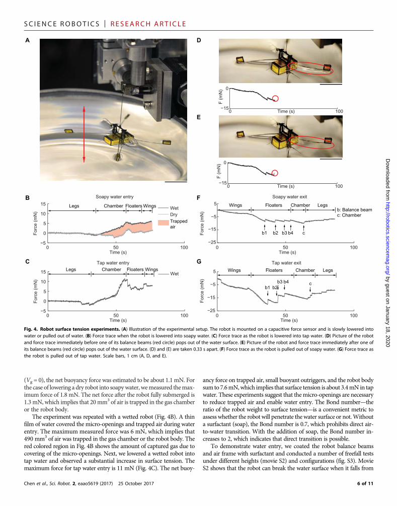
To quantify the surface tension effect on water entry and takeoff, wemounted the robot on a capacitive force sensor (Fig. 4A). The robot waslowered into or pulled out of water at a constant speed of 0.2 mm/s.Weconducted experiments using either soapywater or tapwater and quan-tified the effects of the surfactant. Instead of coating the robot with sur-factant, we put three to five drops of Joy liquid detergent in about 200mlof tap water.
First, we lowered a robot that was completely dry into soapy waterandmeasured the corresponding forces (Fig. 4B). The robot experiencedan upward buoyant force as it was lowered into water. In addition, de-formation of the water surface caused an upward surface tension forceduring water entry. The net buoyant force is given by the sum of con-tributions from the robot body, the sealed buoyant chambers, and the airtrapped in the gas collection chamber:
Fbouy ¼ Fb;robot þ 4rwgVc þ rwgVg ð1Þ
In this equation, rw is the water density, Vc is the small chambervolume, and Vg is the volume of trapped air. Without any trapped air
5 of 11
SC I ENCE ROBOT I C S | R E S EARCH ART I C L E
by guest on January 18, 2020http://robotics.sciencem
ag.org/D
ownloaded from
(Vg = 0), the net buoyancy force was estimated to be about 1.1 mN. Forthe case of lowering a dry robot into soapywater, wemeasured themax-imum force of 1.8 mN. The net force after the robot fully submerged is1.3 mN, which implies that 20mm3 of air is trapped in the gas chamberor the robot body.
The experiment was repeated with a wetted robot (Fig. 4B). A thinfilm of water covered the micro-openings and trapped air during waterentry. The maximum measured force was 6 mN, which implies that490 mm3 of air was trapped in the gas chamber or the robot body. Thered colored region in Fig. 4B shows the amount of captured gas due tocovering of the micro-openings. Next, we lowered a wetted robot intotap water and observed a substantial increase in surface tension. Themaximum force for tap water entry is 11 mN (Fig. 4C). The net buoy-
Chen et al., Sci. Robot. 2, eaao5619 (2017) 25 October 2017
ancy force on trapped air, small buoyant outriggers, and the robot bodysum to 7.6mN,which implies that surface tension is about 3.4mN in tapwater. These experiments suggest that themicro-openings are necessaryto reduce trapped air and enable water entry. The Bond number—theratio of the robot weight to surface tension—is a convenient metric toassess whether the robot will penetrate the water surface or not.Withouta surfactant (soap), the Bond number is 0.7, which prohibits direct air-to-water transition. With the addition of soap, the Bond number in-creases to 2, which indicates that direct transition is possible.
To demonstrate water entry, we coated the robot balance beamsand air frame with surfactant and conducted a number of freefall testsunder different heights (movie S2) and configurations (fig. S3). MovieS2 shows that the robot can break the water surface when it falls from
Soapy water exit
Tap water exit
Wet
b1 b3b2 b4 c
b1b3
b2b4 c
DA
E
FB
GC
Legs Chamber Floaters Wings
Trapped air
Chamber Floaters
Wings Floaters Chamber Legs
0 50 100−5
0
5
10
15Soapy water entry
Time (s)
Forc
e (m
N)
WetDry
0 50 100−25
−15
−5
5
Time (s)
Forc
e (m
N)
0 50 100−5
0
5
10
15
Tap water entry
Time (s)
Forc
e (m
N)
0 50 100−25
−15
−5
5
Time (s)
Forc
e (m
N)
b: Balance beamc: Chamber
Wings Floaters Chamber LegsWingsLegs
0 100−15
0
Time (s)
F (m
N)
0 100−15
0
Time (s)
F (m
N)
Fig. 4. Robot surface tension experiments. (A) Illustration of the experimental setup. The robot is mounted on a capacitive force sensor and is slowly lowered intowater or pulled out of water. (B) Force trace when the robot is lowered into soapy water. (C) Force trace as the robot is lowered into tap water. (D) Picture of the robotand force trace immediately before one of its balance beams (red circle) pops out of the water surface. (E) Picture of the robot and force trace immediately after one ofits balance beams (red circle) pops out of the water surface. (D) and (E) are taken 0.33 s apart. (F) Force trace as the robot is pulled out of soapy water. (G) Force trace asthe robot is pulled out of tap water. Scale bars, 1 cm (A, D, and E).
6 of 11

SC I ENCE ROBOT I C S | R E S EARCH ART I C L E
by guest on January 18, 2020http://robotics.sciencem
ag.org/D
ownloaded from
between 2 and 10 cm above the water surface. Without applying sur-factant, the robot cannot break the water surface. Figure S3 shows suc-cessful robot water entry when it lands from different orientations.
Next, we measured the forces on the robot as it was pulled out ofwater. As the balance beams emerged from the water surface, a thinwater film formed and stretched to the free surface (red circled re-gion of Fig. 4D). This thin film collapsed as the robot continued torise, and consequently each balance beam popped out of the water(Fig. 4E). This motion is captured by the discontinuities in the forceplots (Fig. 4, D to G, and movie S7). The magnitudes of these dis-continuities quantified the surface tension forces on the balance beamsand the chamber. In soapy water, the corresponding forces were 1.3and 1.4 mN (Fig. 4F). We repeated the experiment in tap water (Fig.4G) and measured 3.6- and 4.4-mN force on balance beam and cham-ber, respectively.
We modeled the surface tension forces using the formula (25) Fs≈2gL, where g is the surface tension coefficient and L is the wettedlength. This equation assumes that the floating object is a one-dimensional thin wire. In soapy water, we estimated the surface ten-sion forces on a balance beam and the chamber to be 1.2 and 2.0 mN,respectively. In tap water, the forces increase to 3.6 and 6.0 mN due toa larger g. The estimates agree well with balance beam measurementsbut overpredict the force on the chamber. The discrepancy is largelycontributed by the chamber corners because they do not satisfy theone-dimensional assumption.
The robot has four balance beams and one gas collection chamber.In soapy water and tap water, the total surface forces on these compo-nents are 6.6 and 18.8 mN, respectively. This result suggests that directliftoff from the water surface is infeasible, because a previous work (26)reports a maximum lift of 3.1 mN. In the next section, we describe en-ergetic impulsive mechanisms that enable the water-to-air transition.
Water-to-air transition strategyTo achieve a water-to-air transition, our robot uses a two-step process:gradual surfacing of its wings followed by impulsive takeoff. Uponreaching thewater surface, the electrolytic plates convertwater into oxy-hydrogen. Although the gas collection chamber has micro-openings onits top plate, it can still capture the produced gas through surface tensioneffects. (An extended discussion on micro-opening radius influence ongas collection is given in text S2 and fig. S4.) The gradually increasingbuoyant force of the system gently pushes the robot’s wings out of thewater. In this process, surface tension on the balance beams maintainsthe robot’s upright stability (see text S2 and fig. S5, E and F). This ap-proach protects the delicate wings and transmission from high dragforces experienced upon impulsive transition to air. The second stepgenerates an impulse that breaks the water surface. Previously devel-oped impulsive takeoff methods involved either a fast push off fromthe water surface (19, 27) or chemical reaction–based jet propulsion(11). Because of limited payload, our robot requires a novel methodfor repeatable takeoff. Here, the robot uses reverse electrolysis to acquireenergy for takeoff. Compared with other chemical-based propulsion,this method is repeatable and has benign reaction by-products.
The robot prepares for impulsive takeoff after its wings completelyemerge from the water. At this time, the gas chamber is filled with oxy-hydrogen that contains sufficient energy to break the water surface. Therobot switches off its electrolytic plates and briefly flaps its wings to re-move water residue. Next, a 250-V pulsed signal (Fig. 5A) is sent to thesparker plate, and corona discharge is generated within the 20-mm gapbetween the sparker plate electrodes. We found that the ignition energy
Chen et al., Sci. Robot. 2, eaao5619 (2017) 25 October 2017
is about 0.2 mJ by measuring the corresponding current and pulse du-ration (Fig. 5A). The detonation of oxyhydrogen (28) immediatelyincreased pressure within the gas chamber (Fig. 5B). This detonationcompleted within 1ms, broke the water surface, and exerted an upwardimpulse on the robot. The average upward force generated within thefirst millisecond was between 7.5 and 9 N, resulting in a device thrust-to-weight ratio of 19,000 to 23,000.Without themicro-openings, exces-sive detonation pressure damaged the chamber, balance beams, androbot wings (Fig. 5C). The robot without micro-openings took off at3.4 m/s and experienced large body rotation (Fig. 5D). In contrast,the presence ofmicro-openings reducedmaximumpressure by 3.4 timesand widened the initial pressure pulse width by 39% (Fig. 5B), therebyminimizing structural damage. The chamber with micro-openingsexperienced a smaller pressure rise (Fig. 5B) by releasing gas throughits openings (Fig. 5C). These micro-openings further reduced the ro-bot’s takeoff speed and body rotation (fig. S6, D and E). With themicro-openings, the robot took off at 1.8 m/s and the robot was un-damaged. The balance beams stabilized the takeoff via surface tensionand viscous shear. Consequently, the robot experienced only small bodyrotation during takeoff (Fig. 5D and movie S8). (An extended discus-sion of themicro-opening influence on takeoff is available in text S4 andfigs. S6 and S7.)
Robot landing and post-takeoff flightBecause of motion-tracking limitations, we cannot implement feedbackcontrol for impulsive water surface takeoff. The current Vicon motion-tracking system uses infrared strobe illumination to capture the motionof reflectivemarkers attached to the robot. This system needs to operatein a dark arenawithout reflective surfaces.Water refracts infrared radia-tion and creates very large tracking noise, making optical tracking in-feasible. Instead, the robot passively lands after takeoff (Fig. 2F). Byextracting images from movie S4, we measured the maximum jumpheight to be 37 cm.
We defined a successful landing as the case when the robot landsupright on a surface. The probability of successful landing is dependenton the landing surface. We dropped the robot from 35 cm above differ-ent surfaces and repeated the experiment 10 times. On pretensionednylon cloth, the robot successfully landed 60% of the time. However,the success rate dropped to 10% on stainless steel surfaces. These resultsshow that landing success rate is substantially higher on elastic surfaces.Pretensioned nylon cloth absorbed the landing impact, and there wasvery small subsequent bounce. The bounce magnitude notably increasedon rigid steel surfaces and reduced the landing success rate. This exper-iment suggests that future robot designs may benefit from introducingcompliance to the landing legs or from designs that passively orient therobot while on land.
To verify system repeatability, we conducted a number of static testsand flight experiments after impulsive takeoff and landing. In mostexperiments, the robot experienced no visual damage after transitioningfrom water to land. (Detailed statistics of impulsive takeoff are given intext S4.) The robot was dried naturally, and it was first tested staticallywithout any mechanical modification after the explosion. Figure S8compares the flapping kinematics of the robot operating at 265 Hzbefore and after impulsive takeoff. The robot left and right wing strokeamplitudes before explosion were measured to be 37.5° and 36°, respec-tively. The robot left and right wing stroke amplitudes after explosionwere measured to be 40° and 36°, respectively. This comparison showsthat the robot can generate similar flapping kinematics, which impliesthat its lift capability remains similar.
7 of 11

SC I ENCE ROBOT I C S | R E S EARCH ART I C L E
by guest on January 18, 2020http://robotics.sciencem
ag.org/D
ownloaded from
Furthermore, we show that the robot is capable of demonstratingopen-loop takeoff after explosion. Figure S9 compares the takeoff dem-onstration of the robot before and after explosion. For open-looptakeoff, we only turn on the robot for 0.3 s (~100 flapping periods), be-cause without control the robotmay experience large body rotation andits wings may collide with the safety tether. After explosion, the robotcan still lift off with an average acceleration of 20 cm/s2. This impliesthat the robot can generate a mean lift force larger than its weight afterthe impulsive takeoff.
To achieve similar hovering performance, we performed additionalwing hinge pairing, open-loop trimming, and closed-loop controlparameter identification, because the explosion created small changesto the robot structure. This tuning process was only required forhovering flight and was a regular procedure that was frequently donebetween flight trials. Details of the tuning procedure are given inMaterials and Methods. For cases that involve small visual damages(e.g., lost of a leg or a buoyant outrigger), the robot is also capable of
Chen et al., Sci. Robot. 2, eaao5619 (2017) 25 October 2017
hovering after affixing the component and tuning. This implies thatthe impulsive takeoff does not cause critical damage to the robot’s mainstructure or actuators. However, it creates small changes to theoperating condition such that tuning is needed to demonstrate hovering.Tuning the operating condition is something that could in the future beachieved autonomously through either adaptive control or iterativelearning techniques.
DISCUSSIONOur presentation of a hybrid aerial-aquatic, flapping-wing microrobotincludes (i) a detailed analysis of the observation on robot passiveupright swimming stability in water, (ii) the challenges and benefits im-posed by water surface tension onmillimeter-scale robots, (iii) a discus-sion of mesoscale device design, and (iv) an impulsive water-to-airtransition method. The observation that a flapping-wing vehicle canbe passively stabilized in water can be generalized to larger, traditional
0 1 1.5−200
0
200
400
Time (ms)
Vol
tage
(V)
0.5−2
0
2
4
Cur
rent
(mA
)
−20
6
12
Pre
ssur
e (a
tm)
With openingWithout opening
A
B
C
D
0 ms
2 ms
4 ms
Without openings 0 ms
2 ms
4 ms
With openings
Displacedwater
Displacedwater
Balancebeamblown off
Gas chamber cracks
0 ms
10 ms
20 ms
30 ms
0 ms
20 ms
40 ms
60 ms
VI
Time (ms) 320 1
Without openings
With openings
Fig. 5. Impulsive takeoff from the water surface. (A) Sparker plate input voltage and current when a visible spark is generated. (B) Pressure profile within thechamber upon oxyhydrogen ignition. A reinforced chamber without micro-openings experiences higher pressure than one with micro-openings. (C) Image sequencecomparison of initial robot takeoff. For the robot without chamber micro-openings (left), the detonation cracks the chamber top plate and detaches a robot balancebeam and wing. For the chamber with micro-openings (right), gas and water are released upon ignition, and the robot remains undamaged. (D) Overlaid imagecomparison of robot takeoff. A robot without chamber micro-openings experiences substantial body rotation and has a higher takeoff speed (left). A robot withchamber micro-openings maintains upright stability and has lower takeoff speed (right). Scale bars, 1 cm.
8 of 11

SC I ENCE ROBOT I C S | R E S EARCH ART I C L E
by guest on January 18, 2020http://robotics.sciencem
ag.org/D
ownloaded from
robots. Flapping-wing locomotion in aerial and aquatic environmentsdoes not place constraints on vehicle size and weight. Flapping-wingdesign has a number of favorable features over traditional fixed wingand rotorcraft vehicles. For fixed wing aerial vehicles, aquatic locomo-tion can be inefficient because of large frictional drag on the airfoil sur-face. For rotorcrafts, the vehicle needs to tilt by 90° (12), and thisconfiguration induces large form drag because of the large exposedfrontal area. Furthermore, aerial and aquatic propellers have distinc-tively different shapes because of the difference in fluid properties. Anaerial propeller can cause cavitation in water when it rotates at highspeeds. In contrast, efficient flapping propulsion in water and air doesnot require changes to wing planform (18).
Although previous works consider surface tension and demonstrateeither water surface walking (29) or jumping (19), none addressed thechallenges of air-to-water and water-to-air transition at this scale. Wedeveloped a number of mesoscale devices and features that take advan-tage of surface tension. For instance, the balance beams use surface ten-sion to stabilize the robot on the water surface in preparation forimpulsive takeoff. The gas collection chamber uses surface tensioneffects to capture gas despite the presence of micro-openings on itstop plate. Meanwhile, microrobots need to fight against surface tensionduring these transitions. Surface tension can be reduced by coating therobot with a surfactant for water entry, and it is overcome during watersurface takeoff through an impulsive method. Future aquatic micro-robots may use surface tension to achieve a variety of interesting appli-cations. For instance, surface tension effects may be used to adhere tounderwater surfaces or to control surface tension magnitude to eithermove on the water surface or transition into water.
Our multifunctional microrobot adapts to multiple environments.Traditionally, microrobots have limited functionalities because of con-strained payload (14, 30). To address this challenge, we developedmultifunctional mesoscale devices and demonstrated multimodal lo-comotion strategies. For instance, the micro-openings (Fig. 1F) onthe robot chamber top plate serve multiple functions. When the robotis dry, air within the chamber exits through themicro-openings, reducingbuoyancy and facilitating the air-water transition.When the robot is wet,thin films of water cover the micro-openings due to surface tension. Thegas collection chamber can then generate and capture gas once fullysubmerged in water. Upon combustion-based takeoff, these micro-openings enable excess gas pressure to escape, preventing structuraldamage during detonation. In addition, the multimodal locomotivestrategy allows the robot to use one set of actuation to move in differentenvironments. This robot is an example of bioinspired engineering, butit is also representative of capabilities that go beyond what nature canachieve. Although examples of insects that can perform a water-to-airtransition exist (e.g., whirligig beetle family), none can do so impulsively,largely because of the power density constraints on theirmusculoskeletalsystem and the dominance of surface tension at these scales.
Next-step challengesOur robot cannot yet demonstrate flight immediately upon impulsivetakeoff because of the lack of onboard state estimation sensors andlimitations in our current motion-tracking system. To enable airbornetakeoff from the water surface, future studies will need to incorporateonboard sensors for fast attitude and position feedback. The currenttakeoff speed is about four times the maximum robot flight speed, andthe robot stays aloft for 0.5 s before landing. We estimate that a motion-tracking system of comparable accuracy needs to operate around 1 kHzfor attitude feedback. Furthermore, low-latency controllers need to
Chen et al., Sci. Robot. 2, eaao5619 (2017) 25 October 2017
compensate for disturbances from the impulsive takeoff, water residue,local wind gusts, etc. About 30 to 45 mg of water residue add to thevehicle payload. Although this additional payload is within the currentvehicle’s maximum liftoff capacity, the water residue may offset the ro-bot center of mass and adversely affect hovering. To account for thewater residue, we estimate that a future vehicle needs 30 mg of addi-tional payload capacity and ±0.1 mNm of torque capability for pitch androll control.
MATERIALS AND METHODSRobot fabricationThe robot body and wings are fabricated through processes developedin a previous study (31). Robot actuator, transmission, and wingplanform are redesigned on the basis of recent results (26) to increaseflapping frequency and maximum lift. Each robot half weighs 45 mg.The weight of each component is detailed in table S1.
The gas chamber consists of five rectangular, planar laminates.The top piece is made from 50-mm titanium sheet laminated with12.7-mm polyimide. It is patterned with a rectangular array (39 × 12)of circular holes with 34-mm radius. The four side pieces are made of100-mm carbon fiber laminated with 12.7-mm polyimide. The bottomface is left open for gas collection. The chamber is assembled usingtab-and-slot features to ensure precision and strength. The assembledchamber is glued using Loctite 60 Minute Epoxy. The chamber weighs33 mg and has dimensions of 14 mm × 6.7 mm × 4.9 mm.
Each balance beam consists of two 50-mm titanium pieces. These areassembled manually to form a T-beam using tab-and-slot assembly.Each balance beam is 25 mm long, 400 mm wide, and 400 mm tall andweighs 2 mg.
Each buoyant outrigger has dimensions of 2.5 mm × 2.5 mm ×1mmand attaches to the tip of the balance beam. The buoyant outriggerconsists of three carbon fiber and polyimide laminated pieces: square topand bottom pieces and a foldable side piece. The foldable side piece ismanually folded along compliant flexures. Then, the top and squarepieces are assembled using tab-and-slot features. Last, the box is sealedusing CA glue (Loctite 416).
The sparker plate consists of 150-mm copper clad FR-4 (glass-reinforced epoxy laminate sheet) and 25-mm stainless steel laminatedlayers. FR-4 provides structural support, the copper serves as a solderingpad and sparker material, and the stainless steel is used for electrolysis.The sparker plate has three functional parts: a shared ground, a lowvoltage plate for electrolysis, and a high voltage copper plate for generat-ing sparks. Tether wires are soldered on copper pads, which connect tocorresponding stainless steel plates via conductive epoxy. The sparkerplate weighs 6.5 mg.
Copper is a favorable sparker material because of higher thermalconductivity. Figure S1 (A and B) compares new stainless steel sparkertips and shorted sparker tips. The stainless steel sparker tips fusedtogether after three ignitions, and we observed noticeable discoloration(fig. S1B). In contrast, the copper sparker can ignite over 40 times.
In contrast, the electrolytic plates are made of stainless steel becausecopper anodes easily oxidize in water. Figure S1 compares new copperplates (fig. S1C) and oxidized plates (fig. S1D) after 120 s of use. FigureS1E further highlights an oxidized anode. Consequently, we chose stain-less steel as the anode material. The stainless steel electrolytic plates canoperate for more than 600 s without severe oxidization.
Last, all of the robot componentswere assembled. Four 160-mm-thickcarbon fiber struts securely connected the two robot halves (Fig. 1C).
9 of 11

SC I ENCE ROBOT I C S | R E S EARCH ART I C L E
by guest on January 18, 2020http://robotics.sciencem
ag.org/D
ownloaded from
Then, four balance beams were inserted into the slots on connectionpieces. Next, each buoyant outrigger was attached to a balance beam.Then, the gas collection chamber was inserted between the robot halves(Fig. 1C). The sparker plate was installed to the bottom of the gas collec-tion chamber. Before conducting flight tests, we applied liquid surfactant(Joy liquid detergent) on the robot balance beams, airframe, and gascollection chamber using a microbrush. The robot dried naturally in24 hours. The addedmass from the surfactant was less than 1mg, and itdid not affect flight or swimming capabilities. To avoid spreading sur-factant to water, future studies should consider nondissolving hydro-phobic coatings.
Aerial experiment setupWe conducted the robot hovering demonstration using an existingsetup (14). The closed-loop controller was modified from a previousstudy (8). During the hovering experiment, we attached a safety tetherto the top of the robot to prevent crash landing after flight. To achievegood hovering flight, the robot needed to be mechanically tuned. Thiswas a frequent procedure that took place between flight experiments,and the controller parameters were also updated in the process.
The mechanical tuning procedure is as follows: (i) statically flapthe robot near the resonant frequency (265 Hz) to see whether systemresonance slightly shifts, (ii) adjust robot wings and wing hinges forpairing (this refers to offsetting the wing attachment to account for theslight asymmetry in the left and right wings; this mechanical tuningminimizes the torque asymmetry generated by the two wings), and(iii) perform a number of open-loop flights for choosing the controllerparameters (such as torque bias and mapping from input voltage sig-nal to compensating torque amplitude).
Aquatic experiment setupRobot swimming experiments were conducted in a 30 cm × 15 cm× 15 cm aquarium (fig. S10A). An open-loop controller commandedthe flapping frequency and amplitude through the robot’s tether. Therobot’s swimming kinematics were filmed using a Phantom v7.10 colorcamera. The scenewas illuminated by a light-emitting diode (LED) array.
Robot takeoff and landing experiments were conducted in a beakerof radius 7.5 cm (fig. S10B). A prestretched nylon cloth was placed atthe water level as the landing surface. We filmed the robot takeoffusing a Phantom v7.10 color camera and a v7.3 black and white camera.The scene was illuminated by a VIC 900590P LED array. We useda Kistler 601B1 pressure sensor to measure the detonation pressureupon ignition.
SUPPLEMENTARY MATERIALSrobotics.sciencemag.org/cgi/content/full/2/11/eaao5619/DC1Text S1. Electrolytic plate geometry and efficiency.Text S2. Effect of micro-openings on gas capture.Text S3. Robot stability near the water surface.Text S4. Effect of micro-openings on takeoff.Text S5. Derivation of dynamical model.Text S6. Robot tracking.Text S7. Simplified model of robot passive upright stability.Fig. S1. Material selection of sparker and electrolytic plates, and plate geometry influence onwater resistance during electrolysis.Fig. S2. Swimming demonstration of the new robot design.Fig. S3. Robot water entry from different orientations.Fig. S4. Surface tension influence on height of the gas collection chamber.Fig. S5. Robot stability near the water surface.Fig. S6. Influence of micro-openings on takeoff speed.Fig. S7. Influence of micro-openings on ignition pressure and takeoff speed.
Chen et al., Sci. Robot. 2, eaao5619 (2017) 25 October 2017
Fig. S8. Comparison of flapping kinematics before and after impulsive takeoff.Fig. S9. Robot liftoff demonstration before and after impulsive takeoff.Fig. S10. Experimental setup.Fig. S11. Dynamical model and motion-tracking method.Fig. S12. Robot stability during freefall and swimming.Table S1. Properties of robot components.Table S2. Model parameter values.Movie S1. Demonstration of robot aerial hover.Movie S2. Demonstration of robot air-water transition.Movie S3. Demonstration of robot swimming and emergence of robot wing from the watersurface.Movie S4. Demonstration of robot impulsive takeoff and landing.Movie S5. Comparison of robot underwater stability with different flapping frequencies.Movie S6. Comparison between robot swimming experiment and simulation.Movie S7. Measurement of surface tension force on a robot during water-to-air transition.Movie S8. Comparison of robot takeoff with or without micro-openings on gas collectionchamber.Movie S9. Detonation pressure measurement and robot takeoff.References (32–35)
REFERENCES AND NOTES1. S. Sudo, T. Yano, Y. Kan, Y. Yamada, K. Tsuyuki, Swimming behavior of small diving
beetles. J. Adv. Sci. 18, 46–49 (2006).2. R. J. Lock, R. Vaidyanathan, S. C. Burgess, J. Loveless, Development of a biologically
inspired multi-modal wing model for aerial-aquatic robotic vehicles through empiricaland numerical modelling of the common guillemot, Uria aalge. Bioinspir. Biomim. 5,046001 (2010).
3. J. Davenport, How and why do flying fish fly? Rev. Fish Biol. Fish. 4, 184–214 (1994).4. H. Park, H. Choi, Aerodynamic characteristics of flying fish in gliding flight. J. Exp. Biol.
213, 3269–3279 (2010).5. J. M. V. Rayner, Pleuston: Animals which move in water and air. Endeavour 10, 58–64
(1986).6. R. R. Murphy, E. Steimle, C. Griffin, C. Cullins, M. Hall, K. Pratt, Cooperative use of
unmanned sea surface and micro aerial vehicles at Hurricane Wilma. J. Field Robot. 25,164–180 (2008).
7. K. Jayaram, J.-M. Mongeau, B. McRae, R. J. Full, High-speed horizontal to verticaltransitions in running cockroaches reveals a principle of robustness. Integr. Comp. Biol.50, E83 (2010).
8. P. Chirarattananon, K. Y. Ma, R. J. Wood, Perching with a robotic insect using adaptivetracking control and iterative learning control. Int. J. Robot. Res. 35, 1185–1206 (2016).
9. M. A. Graule, P. Chirarattananon, S. B. Fuller, N. T. Jafferis, K. Y. Ma, M. Spenko, R. Kornbluh,R. J. Wood, Perching and takeoff of a robotic insect on overhangs using switchableelectrostatic adhesion. Science 352, 978–982 (2016).
10. R. Eubank, E. Atkins, G. Meadows, Unattended operation of an autonomous seaplanefor persistent surface and airborne ocean monitoring, Oceans MTS-IEEE Conference,Seattle, WA, 20 to 23 September 2010 (IEEE, 2010).
11. R. Siddall, M. Kovač, Launching the AquaMAV: Bioinspired design for aerial–aquaticrobotic platforms. Bioinspir. Biomim. 9, 031001 (2014).
12. M. M. Maia, P. Soni, F. J. Diez, Demonstration of an aerial and submersible vehicle capableof flight and underwater navigation with seamless air-water transition. http://arxiv.org/abs/1507.01932 (2015).
13. Z. J. Wang, J. M. Birch, M. H. Dickinson, Unsteady forces and flows in low Reynoldsnumber hovering flight: Two-dimensional computations vs robotic wing experiments.J. Exp. Biol. 207, 449–460 (2004).
14. K. Y. Ma, P. Chirarattananon, S. B. Fuller, R. J. Wood, Controlled flight of a biologicallyinspired, insect-scale robot. Science 340, 603–607 (2013).
15. M. H. Dickinson, F.-O. Lehmann, S. P. Sane, Wing rotation and the aerodynamic basis ofinsect flight. Science 284, 1954–1960 (1999).
16. Y. Chen, N. Gravish, A. L. Desbiens, R. Malka, R. J. Wood, Experimental and computationalstudies of the aerodynamic performance of a flapping and passively rotating insectwing. J. Fluid Mech. 791, 1–33 (2016).
17. D. W. Murphy, D. Adhikari, D. R. Webster, J. Yen, Underwater flight by the planktonic seabutterfly. J. Exp. Biol. 219, 535–543 (2016).
18. Y. Chen, E. F. Helbling, N. Gravish, K. Y. Ma, R. J. Wood, Hybrid aerial and aquaticlocomotion in an at-scale robotic insect, IEEE/RSJ International Conference onIntelligent Robots and Systems, Hamburg, Germany, 28 September to 2 October 2015(IEEE, 2015), pp. 331–338.
19. J.-S. Koh, E. Yang, G.-P. Jung, S.-P. Jung, J. H. Son, S.-I. Lee, P. G. Jablonski, R. J. Wood,H.-Y. Kim, K.-J. Cho, Jumping on water: Surface tension–dominated jumping of waterstriders and robotic insects. Science 349, 517–521 (2015).
10 of 11
SC I ENCE ROBOT I C S | R E S EARCH ART I C L E
http://D
ownloaded from
20. R. J. Wood, S. Avadhanula, R. Sahai, E. Steltz, R. S. Fearing, Microrobot design using fiberreinforced composites. J. Mech. Des. 130, 052304 (2008).
21. Y. Chen, K. Ma, R. J. Wood, Influence of wing morphological and inertial parameters onflapping flight performance, IEEE/RSJ International Conference on Intelligent Robots andSystems, Daejeon, South Korea, 9 to 14 October 2016 (IEEE, 2016), pp. 2329–2336.
22. M.-S. Park, Y.-R. Jung, W.-G. Park, Numerical study of impact force and ricochet behaviorof high speed water-entry bodies. Comput. Fluids 32, 939–951 (2003).
23. T. M. Wang, X. B. Yang, J. H. Liang, G. C. Yao, W. D. Zhao, CFD based investigation on theimpact acceleration when a gannet impacts with water during plunge diving.Bioinspir. Biomim. 8, 036006 (2013).
24. S. Garthe, S. Benvenuti, W. A. Montevecchi, Pursuit plunging by northern gannets(Sula bassana) “feeding on capelin (Mallotus villosus).” Proc. Biol. Sci. 267, 1717–1722(2000).
25. D. Vella, J. Li, The impulsive motion of a small cylinder at an interface. Phys. Fluids 22,052104 (2010).
26. N. T. Jafferis, M. A. Graule, R. J. Wood, Non-linear resonance modeling and systemdesign improvements for underactuated flapping-wing vehicles, IEEE InternationalConference on Robotics and Automation, Stockholm, Sweden, 16 to 21 May 2016(IEEE, 2016), pp 3234–3241.
27. M. Burrows, Jumping from the surface of water by the long-legged fly Hydrophorus(Diptera, Dolichopodidae). J. Exp. Biol. 216, 1973–1981 (2013).
28. D. H. Edwards, G. T. Williams, J. C. Breeze, Pressure and velocity measurements ondetonation waves in hydrogen-oxygen mixtures. J. Fluid Mech. 6, 497–517 (1959).
29. D. L. Hu, B. Chan, J. W. M. Bush, The hydrodynamics of water strider locomotion.Nature 424, 663–666 (2003).
30. E. Diller, J. Giltinan, M. Sitti, Independent control of multiple magnetic microrobots inthree dimensions. Int. J. Robot. Res. 32, 614–631 (2013).
31. J. P. Whitney, P. S. Sreetharan, K. Y. Ma, R. J. Wood, Pop-up book MEMS.J. Micromech. Microeng. 21, 115021 (2011).
Chen et al., Sci. Robot. 2, eaao5619 (2017) 25 October 2017
32. N. Nagai, M. Takeuchi, T. Kimura, T. Oka, Existence of optimum space between electrodeson hydrogen production by water electrolysis. Int. J. Hydrogen Energy 28, 35–41 (2003).
33. T. L. Geers, K. S. Hunter, An integrated wave-effects model for an underwater explosionbubble. J. Acoust. Soc. Am. 111, 1584–1601 (2002).
34. M. W. Spong, S. Hutchinson, M. Vidyasagar, Dynamics, in Robot Modeling and Control(Wiley, 2006), vol. 3, pp. 239–285.
35. J. P. Whitney, R. J. Wood, Aeromechanics of passive rotation in flapping flight.J. Fluid Mech. 660, 197–220 (2010).
Acknowledgments: We thank J. Koh for comments and discussions. Funding: This material isbased upon work supported by the NSF (award no. 1537715), an NSF Graduate ResearchFellowship under grant no. DGE1144152, and the Wyss Institute for Biologically InspiredEngineering. In addition, the prototypes were enabled by equipment supported by the ArmyResearch Office DURIP program (award no. W911NF-13-1-0311). Any opinions, findings, andconclusions or recommendations expressed in this material are those of the authors anddo not necessarily reflect the views of the NSF. Author contributions: Y.C. designed the robot.Y.C., H.W., E.F.H., N.T.J., and A.O. conceived the experimental work. Y.C., H.W., E.F.H., R.Z., P.C.,and R.J.W. contributed to modeling and data analysis. Y.C. wrote the paper. All authorsprovided feedback. Competing interests: The authors declare that they have no competinginterests. Data and materials availability: Please contact Y.C. for data and other materials.
Submitted 2 August 2017Accepted 3 October 2017Published 25 October 201710.1126/scirobotics.aao5619
Citation: Y. Chen, H. Wang, E. F. Helbling, N. T. Jafferis, R. Zufferey, A. Ong, K. Ma, N. Gravish,P. Chirarattananon, M. Kovac, R. J. Wood, A biologically inspired, flapping-wing, hybrid aerial-aquatic microrobot. Sci. Robot. 2, eaao5619 (2017).
rob11 of 11
by guest on January 18, 2020otics.sciencem
ag.org/

A biologically inspired, flapping-wing, hybrid aerial-aquatic microrobot
Gravish, Pakpong Chirarattananon, Mirko Kovac and Robert J. WoodYufeng Chen, Hongqiang Wang, E. Farrell Helbling, Noah T. Jafferis, Raphael Zufferey, Aaron Ong, Kevin Ma, Nicholas
DOI: 10.1126/scirobotics.aao5619, eaao5619.2Sci. Robotics
ARTICLE TOOLS http://robotics.sciencemag.org/content/2/11/eaao5619
MATERIALSSUPPLEMENTARY http://robotics.sciencemag.org/content/suppl/2017/10/23/2.11.eaao5619.DC1
REFERENCES
http://robotics.sciencemag.org/content/2/11/eaao5619#BIBLThis article cites 29 articles, 8 of which you can access for free
PERMISSIONS http://www.sciencemag.org/help/reprints-and-permissions
Terms of ServiceUse of this article is subject to the
is a registered trademark of AAAS.Science RoboticsNew York Avenue NW, Washington, DC 20005. The title (ISSN 2470-9476) is published by the American Association for the Advancement of Science, 1200Science Robotics
of Science. No claim to original U.S. Government WorksCopyright © 2017 The Authors, some rights reserved; exclusive licensee American Association for the Advancement
by guest on January 18, 2020http://robotics.sciencem
ag.org/D
ownloaded from


![Dynamics and flight control of a flapping- wing robotic ... · aerodynamics of flapping-wing flight [8,13–15]. Despite having achieved stable flight, the flapping-wing robot in](https://static.fdocuments.us/doc/165x107/5e232a06436fd7265e4f446b/dynamics-and-flight-control-of-a-flapping-wing-robotic-aerodynamics-of-flapping-wing.jpg)