A BIOLOGICALLY-INSPIRED DYNAMIC LEGGED...
7
1 Copyright © 2008 by ASME Proceedings of DSCC 2008 ASME 2008 Dynamic Systems and Control Conference October 20-22, 2008, Ann Arbor, Michigan, USA DSCC2008-12345 A BIOLOGICALLY-INSPIRED DYNAMIC LEGGED LOCOMOTION WITH A MODULAR RECONFIGURABLE ROBOT Jimmy Sastra Mechanical Engineering and Applied Mechanics University of Pennsylvania Philadelphia, PA 19103 [email protected] Willy Giovanni Bernal Heredia Mechanical Engineering and Applied Mechanics University of Pennsylvania Philadelphia, PA 19103 [email protected] Jonathan Clark Mechanical Engineering FAMU/FSU College of Engineering Tallahassee, FL 32310 [email protected] Mark Yim Mechanical Engineering and Applied Mechanics University of Pennsylvania Philadelphia, PA 19103 [email protected] ABSTRACT Reconfigurable Modular robots can adapt their morphology and their gaits for locomotion to different types of environment, whether like a snake for constrained spaces or a wheeled like shape for efficient and fast locomotion on flat terrain. This paper proposes a scalable biologically-inspired legged style of locomotion. It proposes a modular robot with legs that are compliant. The legs are purely passive with no actuators and locomotion is achieved using pure body articulation. Results are shown of a dynamical bouncing gait utilizing this hexapod configuration with a Spring Loaded Inverted Pendulum (SLIP) template for a dynamical model. The model and control is such that it is easily scalable to any number of legs, however this work presents a 6 legged implementation. INTRODUCTION While running animals exist in a wide variety of shapes and sizes, biomechanical studies have shown that there are amazing similarities in the underlying dynamics of two, four, six, eight, and even forty-four legged creatures. These similarities inspired the development and analysis of elegantly simple dynamic models such as the sagittal-plane Spring-Loaded Inverted Pendulum (SLIP). The SLIP model was first proposed in the late 1970s [1] and the applicability of the model to the locomotion dynamics of a range of animals was demonstrated through the 1980s and 1990s [2,3]. The slip model, as shown in Figure 1, consists of a single point mass representing the runner’s body attached to a mass-less, prismatic, hooks-law spring which is intermittently attached to the ground via a frictionless revolute joint. This ‘leg’ is positioned during flight to touch down at a given angle. During stance the spring compresses as the point mass rotates as an inverted pendulum about the foot until the spring extension reaches the rest length and the flight phase begins. In Figure 1 only a single leg is shown for clarity as the left-right symmetry of motion in the saggital plane renders each steady-state step equivalent. Despite the simplicity of the dynamic model, the SLIP ‘template’ [4], manages to accurately capture the horizontal and vertical whole- body ground reaction forces and center of mass motions for a wide variety of running systems. FIGURE 1 - SLIP MODEL AND GROUND REACTION FORCES Variants of this basic model have proven useful in explaining the relative leg stiffness of animals at greatly different scales [5], the relationship between leg stiffness, speed, size, and stride frequency [6,7], how humans adjust their legs stiffness to different surfaces [8], and in predicting how leg re-circulation strategies affect the stability of running [9]. More recently they have begun to serve as platforms for investigating locomotion control schemes including how neuromuscular models are designed to control locomotion tasks [10,11,12]. In short, they provide the foundation for our understanding of running. Insights gained from these models have led to the development of fast running robots. The first dynamic legged machines built by Raibert and Hodgins mimicked the pogo-stick morphology of the SLIP model and
Transcript of A BIOLOGICALLY-INSPIRED DYNAMIC LEGGED...

1 Copyright © 2008 by ASME
Proceedings of DSCC 2008 ASME 2008 Dynamic Systems and Control Conference
October 20-22, 2008, Ann Arbor, Michigan, USA
DSCC2008-12345
A BIOLOGICALLY-INSPIRED DYNAMIC LEGGED LOCOMOTION WITH A MODULAR RECONFIGURABLE ROBOT
Jimmy Sastra
Mechanical Engineering and Applied Mechanics University of Pennsylvania
Philadelphia, PA 19103 [email protected]
Willy Giovanni Bernal Heredia Mechanical Engineering and Applied Mechanics
University of Pennsylvania Philadelphia, PA 19103 [email protected]
Jonathan Clark
Mechanical Engineering FAMU/FSU College of Engineering
Tallahassee, FL 32310 [email protected]
Mark Yim Mechanical Engineering and Applied Mechanics
University of Pennsylvania Philadelphia, PA 19103 [email protected]
ABSTRACT Reconfigurable Modular robots can adapt their morphology
and their gaits for locomotion to different types of environment, whether like a snake for constrained spaces or a wheeled like shape for efficient and fast locomotion on flat terrain. This paper proposes a scalable biologically-inspired legged style of locomotion. It proposes a modular robot with legs that are compliant. The legs are purely passive with no actuators and locomotion is achieved using pure body articulation. Results are shown of a dynamical bouncing gait utilizing this hexapod configuration with a Spring Loaded Inverted Pendulum (SLIP) template for a dynamical model. The model and control is such that it is easily scalable to any number of legs, however this work presents a 6 legged implementation.
INTRODUCTION While running animals exist in a wide variety of shapes and
sizes, biomechanical studies have shown that there are amazing similarities in the underlying dynamics of two, four, six, eight, and even forty-four legged creatures. These similarities inspired the development and analysis of elegantly simple dynamic models such as the sagittal-plane Spring-Loaded Inverted Pendulum (SLIP). The SLIP model was first proposed in the late 1970s [1] and the applicability of the model to the locomotion dynamics of a range of animals was demonstrated through the 1980s and 1990s [2,3].
The slip model, as shown in Figure 1, consists of a single point mass representing the runner’s body attached to a mass-less, prismatic, hooks-law spring which is intermittently attached to the ground via a frictionless revolute joint. This ‘leg’ is positioned during flight to touch down at a given angle. During stance the
spring compresses as the point mass rotates as an inverted pendulum about the foot until the spring extension reaches the rest length and the flight phase begins. In Figure 1 only a single leg is shown for clarity as the left-right symmetry of motion in the saggital plane renders each steady-state step equivalent. Despite the simplicity of the dynamic model, the SLIP ‘template’ [4], manages to accurately capture the horizontal and vertical whole-body ground reaction forces and center of mass motions for a wide variety of running systems.
FIGURE 1 - SLIP MODEL AND GROUND REACTION FORCES
Variants of this basic model have proven useful in explaining the relative leg stiffness of animals at greatly different scales [5], the relationship between leg stiffness, speed, size, and stride frequency [6,7], how humans adjust their legs stiffness to different surfaces [8], and in predicting how leg re-circulation strategies affect the stability of running [9]. More recently they have begun to serve as platforms for investigating locomotion control schemes including how neuromuscular models are designed to control locomotion tasks [10,11,12]. In short, they provide the foundation for our understanding of running. Insights gained from these models have led to the development of fast running robots. The first dynamic legged machines built by Raibert and Hodgins mimicked the pogo-stick morphology of the SLIP model and
2 Copyright © 2008 by ASME
showed that artificial legged systems can be both fast and agile [13]. More recently, insect-inspired sprawled-posture robots with compliant legs such as Sprawlita and RHex have been built which enable fast running over rough and unknown terrain [14,15].
These results show that proper passive compliance in the limbs and periodic actuation of the limbs is sufficient to achieve dynamic legged locomotion. The question remains, however, how applicable is this reduced-order SLIP model to dynamic robots in general. Can this template be instantiated or anchored in morphologies that are radically different than animals or pogo-sticks?
This paper describes our efforts to imbue a chain-style modular robot, CkBot[18] with dynamic running capabilities by re-imagining it as a SLIP-like runner.
Modular robots have employed a variety of biologically inspired locomotion schemes. PolyBot, for example, has been shown to implement a variety of snake like gaits, including rectilinear undulation[16], sidewinding, and concertina well as simple statically stable quadruped gaits with body articulation similar to a lizard[16] and a 14 legged centipede[17]. Though diverse in their structure, all of these gaits were quasi-static in nature.
Modular robots have also recently demonstrated some forms of dynamic locomotion (where inertial terms can not be ignored in the equations of motion). In particular, CkBot has been used in a rolling loop gait that resulted in a fast motion[18] but was not biologically inspired and is restricted to smooth surfaces. But these are few in comparison to quasi-static gaits. Typically, chain style reconfigurable robot modules such as CKbot, PolyBot[24], MTRAN[19], Conro[20], and Superbot[21] all tend to be designed with large torque capability – large gear ratios, so the modules tend to be rather slow. We overcome this limitation of the base robotic platform by the development of specialized, light-weight, module attachments (described in the next section) and the adoption of a body articulation pattern that aims to produce SLIP like ground-reaction patterns and center of mass motions.
By demonstrating the first dynamic running robot without leg articulation we aim to highlight the broad versatility and applicability of the SLIP template abstraction to inspire and control running platforms. In this case we also seek to imbue a modular chain-type reconfigurable robot with locomotion capabilities previously assumed to be only available to machines with complex limbs or distributed distal actuators.
LEGGED GAIT DESCRIPTION The configuration of modules presented in this paper is
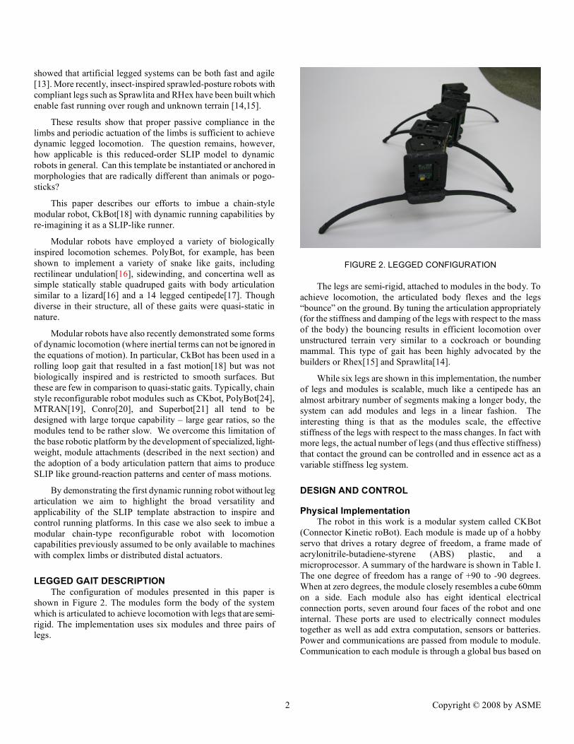
shown in Figure 2. The modules form the body of the system which is articulated to achieve locomotion with legs that are semi-rigid. The implementation uses six modules and three pairs of legs.
FIGURE 2. LEGGED CONFIGURATION
The legs are semi-rigid, attached to modules in the body. To achieve locomotion, the articulated body flexes and the legs “bounce” on the ground. By tuning the articulation appropriately (for the stiffness and damping of the legs with respect to the mass of the body) the bouncing results in efficient locomotion over unstructured terrain very similar to a cockroach or bounding mammal. This type of gait has been highly advocated by the builders or Rhex[15] and Sprawlita[14].
While six legs are shown in this implementation, the number of legs and modules is scalable, much like a centipede has an almost arbitrary number of segments making a longer body, the system can add modules and legs in a linear fashion. The interesting thing is that as the modules scale, the effective stiffness of the legs with respect to the mass changes. In fact with more legs, the actual number of legs (and thus effective stiffness) that contact the ground can be controlled and in essence act as a variable stiffness leg system.
DESIGN AND CONTROL
Physical Implementation The robot in this work is a modular system called CKBot
(Connector Kinetic roBot). Each module is made up of a hobby servo that drives a rotary degree of freedom, a frame made of acrylonitrile-butadiene-styrene (ABS) plastic, and a microprocessor. A summary of the hardware is shown in Table I. The one degree of freedom has a range of +90 to -90 degrees. When at zero degrees, the module closely resembles a cube 60mm on a side. Each module also has eight identical electrical connection ports, seven around four faces of the robot and one internal. These ports are used to electrically connect modules together as well as add extra computation, sensors or batteries. Power and communications are passed from module to module. Communication to each module is through a global bus based on

3 Copyright © 2008 by ASME
the RoboticsBus protocol [22] which is built on the CANbus standard (Controller Area Network).
TABLE 1. TECHNICAL SPECIFICATIONS FOR A CKBOT MODULE
Properties Value
Mass (per module) 138(g)
Size (per module) W60xL60xH60(mm)
Batteries Lithium Polymer 7.4V
MCU PIC18f2680
Servo Airtronics 94359
Torque 1.4Nm
Transit Time 0.10sec/60deg
Reconfiguration Manual
There are two types of CKBot modules used as shown in
Figure 3. Figure 3A shows a regular module, whereas Figure 3B shows an L7 module. To obtain the six-legged configuration for this work, six modules are used with three pairs of legs cut out of ABS. Two sets of three modules (an L7 module sandwiched between two regular modules) sit between the three pairs of legs. The regular modules allow the legs to move left and right in the horizontal plane whereas the L7 modules function to twist the legs with respect to each other in the vertical plane.
FIGURE 3. A) REGULAR MODULE AND B) L7 MODULE
Control Each module uses a highly tuned proprietary position
controller to control its local angle. Position commands are sent from an outside controller (laptop) to each of the modules to obtain the desired overall motion.
Gait Table
The robot is controlled using a gait table consisting of 6 columns. The elements in the table correspond to joint angles in
degrees of modules in the columns and the step in time by the rows. Table 2 shows the gait table used for the six legged configuration for forward locomotion. Smooth motion is achieved by linearly interpolating the angles between each time step.
TABLE 2. GAIT TABLE FOR 6 LEGGED CONFIGURATION
reg L7 reg reg L7 reg
-25 -20 -25 25 20 25
-25 -20 -25 25 20 25
25 -55 25 -25 55 -25
25 20 25 -25 -20 -25
25 20 25 -25 -20 -25
-25 55 -25 25 -55 25
The gait table above achieves a simple alternating tripod gait for the centipede robot. In an alternating tripod gait the front and rear legs on one side move together with the middle leg on the other side. One step of the motion is shown schematically in Figure 4 in the horizontal plane. A filled circle denotes a foot on the ground whereas an open circle denotes a foot in the air. In this case the front and rear legs on the right side and the middle leg on the left side provide the triangle of support. The motion shown is achieved solely by changing the angles of the regular modules (1st, 3rd, 4th and 6th modules). To alternate the tripod to the other legs only the L7 modules (2nd and 5th modules) are used to twist the legs with respect to each other so that the other legs provide the support. The stepping motion is then repeated.
FIGURE 4. TRIPOD GAIT
Constraints to two DOF

4 Copyright © 2008 by ASME
To simplify the control of this robot the six degrees of freedom are constrained to two by slaving all the regular modules to mirror each other for control of the horizontal motion. The L7 modules are also slaved to mirror each other and provide the twisting motion between the legs that allows the robot to hop in place. Thus the commands to allow the centipede of arbitrary number of legs to move forward is simplified to two degrees of freedom: reciprocating forward and backward motion of the legs in the horizontal plane and twisting motion in the vertical plane.
EXPERIMENTAL RESULTS The primary objective of this platform is to demonstrate forward locomotion that takes advantage of dynamic properties in the gait. As is shown in other robots with SLIP like locomotion, there typically exists a resonant frequency at which the fastest locomotion is achieved. To test for the existence of this phenomenon, the driving frequency of the actuation scheme is varied and resulting forward velocity of the robot is measured.
The gait table contains 6 steps and speeds were tested at 1, 5, 10, 20 and 25 steps per second. This corresponds to frequencies of 0.2, 0.8, 1.7, 2.5, 3.3, 4.2 Hz respectively. Thus the frequency of the gait is defined as the time it takes for the controller to cycle through the table which describes the motion for each leg to go through a full cycle.
FIGURE 5. VELOCITY VS. GAIT FREQUENCY
Figure 5 shows that forward velocity increases until 3.3Hz at which the maximum velocity is achieved. . Further increasing the frequency of the gait beyond this point results in decreasing speeds.
Empirical observation suggests that the gait is statically stable at frequencies below 1Hz. In this regime, since the length of each step is constant, the velocity of the robot is correlated linearly with the gait frequency. At 1.7Hz we see that the velocity is higher than if we were to linearly extrapolate the predicted statically stable velocity from the previous data points shown with a dashed line. At this frequency, the gait of the robot now contains a flight phase in which the robot moves forward faster than the legs would if they maintained contact on the ground. The
robot is thus moving farther with each step as well as having faster steps with the higher gait frequency.
Beyond 1.7 Hz the forward velocity does not increase as much. At 2.5Hz and 3.3Hz the velocity is faster but only 0.7 m/s. Even though the frequency of the gait is increased it is hypothesized that the robot does not take advantage of the flight phase. The portions of the legs that would be the ground contact points start to move as fast as the body moving through the air. From an energetic point of view, the legs may be releasing the stored energy in the compliant legs at the wrong time.
At 4.2Hz the gait is shown to even slow down. It is seen from video that the joint angle motion (independent of a flight phase) are significantly smaller. The speed limit of the servos is reached and so cannot keep up with the commanded positions at that frequency. The full stride is not achieved.
FIGURE 6. DYNAMIC MODEL
DYNAMIC MODEL An analytical model can be used to help understand the locomotion mechanism. The model computes the jumping height at different gait frequencies. The intuition is that the height can be used to determine locomotion characteristics such as forward speed and ability to traverse obstacles.
The SLIP model lumps the entire mass of the vehicle or animal as one rigid body and all legs as a single spring. For robots such as Sprawlita or RHex which have a rigid body and compliant limbs, the mapping to the SLIP model is straightforward. For the centipede with its body articulation a slightly more complicated

5 Copyright © 2008 by ASME
model is necessary to illuminate how the body dynamics relate to the to the actuated body degrees of freedom.
To capture these differences the dynamics of a 2n legged hopper can be simplified by observing one segment that contains three modules between two pairs of legs in a reductionist manner similar to that of the SLIP model. Under ideal conditions, with 2n legs, n legs make contact with the ground at the same time.
Our initial modeling effort only considers the one dimensional hopping height of the vehicle. For this we can ignore the module used for body articulation in the horizontal plane and we are left with two modules which rotate about the horizontal axis in the sagittal plane. Figure 6 shows a schematic of this model in the coronal plane. Two legs are rigidly attached to each module shown as lines emerging from two corners of square module. The leg ground contacts are modeled a spring damper system.
This model was simulated numerically in MATLAB™. Since the servos in the two modules are commanded in a symmetric fashion, they are modeled as imparting a moment in equal and opposite directions between the two rigid pairs of legs.
Before validating this model, we need to find the four key parameters in the model that match the physical implementation. These parameters are the mass of the system, the effective virtual spring constant of the legs, the damping coefficient of the legs and the torque imparted by the controller.
The mass of the system is directly determined by weighing the modules. The weight of the legs is considered to be small with respect to the mass of the modules and so is neglected. The torque from the servos is modeled as a simple Proportional-Derivative controller. The gains were determined empirically to match the resonant response as the physical system. The desired angle actuation profile given to the model is interpolated to obtain a smooth and nearly constant angular speed to match the observed behavior of the robot. The servo motor's maximum torque and angular speed constraints were also modeled as specified by the maker.
A finite element analysis was used to calculate the effective vertical leg stiffness when deflected along different angles with respect to the horizontal, a typical result of which is shown in Figure 7. The resulting stiffness as a function of touchdown angle is plotted in Figure 8. A fourth order polynomial is fit to this data to give us an expression how leg stiffness changes with the landing angle.
The damping coefficient is measured by observing the settling time and damped natural frequency of the leg subject to a step disturbance. The displacement response for these legs was measured using a SONY HDR HC7 camera at 120 frames/second.
The resulting equations of motions are implemented using ODE45 in MATLAB and used to evaluate the effect of altering the actuation scheme on the vertical hopping dynamics of the centipede.
FIGURE 7. FINITE ELEMENT ANALYSIS OF DEFLECTION
FIGURE 8. STIFFNESS VS ANGLE
ANALYTICAL RESULTS Values for steady state height at different gait frequencies were gathered from the MATLAB simulation. This steady state hopping height is plotted as a function of the input gait frequency in Figure 9 which shows a peak at 1.67 Hz. For this value the natural frequency of the model will be close to the driving frequency.
Transient behavior of the centipede is also modeled. Figure 10 shows how the systems reaches steady state at 2.33 Hz, where there are some initial instabilities that subsequently die out. For some frequencies, the model did not reach a constant jump height, but presented a periodic behavior. This behavior was observed at 2.5 Hz and is presented in Figure 11.
We can plot the height of the centipede along with the relative angle between the regular modules to compare the centipede natural frequency and the driving frequency. Intuitively, the driving function should be equal or have some phase lead relative to the ground contact reaction. In Figure 12 a foot landing is indicated by sudden upward swing of the height after falling some distance. It can be seen that that landing occurs slightly before the driving function. This plot proved helpful when attempting to match the driving frequency to the system natural frequency. The gait frequency was changed until take off occurred when the servo

6 Copyright © 2008 by ASME
tried to go from 20 to 55 degrees, the point where the input torque achieves a maximum.
FIGURE 9. VELOCITY VS. GAIT FREQUENCY
FIGURE 10. HEIGHT VS. TIME
FIGURE 11. HEIGHT VS. TIME
FIGURE 12. ANGLE BETWEEN MODULES AND HEIGHT VS.
TIME
CONCLUSION A novel biologically inspired modular gait has been implemented using articulated body motions and compliant springy legs. The gait can be thought of in two parts as motion in the vertical plane to achieve hopping and motion in the horizontal plane to achieve forward locomotion. Analysis has been presented on the vertical dynamics. It is shown analytically that there exists a resonant frequency of the system that maximizes hopping height. Once the resonant frequency is found, horizontal motion can be incorporated to take advantage of this flight phase. Although the horizontal motion has not yet been incorporated in the model, it has been included in the experimental setup.
In the experimental setup it has been shown that at low frequencies the velocity is linear with respect to the gait frequency. However a higher velocity is achieved at the resonant frequency which is in agreement with the analytical model. It is hypothesized that at this gait frequency the robot is taking advantage of the flight phase provided by the vertical hopping motion but more accurate measurements need to be made to verify this.
While the bending of the legs in the vertical plane are incorporated in the model, the horizontal bending is not included. This horizontal spring component maybe simply analyzed in a decoupled fashion, though this is left for future work.
In addition, more data has been collected for the jumping height of the physical system at different frequencies however, the data has not been processed at the time of this writing. Preliminary experimentation of scaling up the number of leg/module segments have indicated that the simple reductionist model of collapsing all legs to two degrees of freedom does not adequately model the behavior. This too is left for future work.

7 Copyright © 2008 by ASME
REFERENCES [1] Cavagna, G. A., Heglund, N. C., and Taylor, C. R.,
“Mechanical work in terrestrial locomotion: Two basic mechanisms for minimizing energy expenditure”. American J of Physiology, vol. 233, 1977.
[2] Blickhan, R. and Full, R. J., “Similarity in multilegged locomotion: Bounding like a monopod”. J of Comparative Physiology, 173(5), pp. 509–517, 1993.
[3] Full, R. J., Blickhan, R., and Ting L. H., “Leg design in hexapedal runners”. J of Experimental Biology,. 158,(UL), pp. 369–390, 1991.
[4] Full, R., and Koditschek, D.E., “Templates and Anchors: neuromechanical hypothesis of legged locomotion on land.” J of Experimental Biology, 83:33250333, 1999
[5] Blickhan, R., “The spring-mass model for running and hopping”. J of Biomechanics. 22(11-12), pp. 1217–27, 1989.
[6] Farley, C. T., Glasheen, J., and McMahon, T. A., “Running springs - speed and animal size”. J of Experimental Biology, vol. 185, pp. 71–86, 1993.
[7] Farley, C., “Leg stiffness andstride frequency in human running”. J of Biomechanics. 29,(2), pp. 181–186, 1996.
[8] Ferris, D. P., Louie, M., and Farley, C. T., “Running in the real world: adjusting leg stiffness for different surfaces”. Proc. of the Royal Society,. 265(1400), pp. 989–994, 1998.
[9] Seyfarth, A., Geyer, H., and H. Herr, “Swing-leg retraction: a simple control model for stable running”. J of Experimental Biology, vol. 206, pp. 2547–2555, 2003.
[10] Saranil, U. and Koditschek, D. E., “Template based contorl of hexapedal running”. in Proc. IEEE ICRA ’03, 14-19 Sept, 2003.
[11] Kimuar, H., Akiyama, S., and Sakurama, K., “Realization of dynamic walking and running of the quadruped using neural oscillator”. Autonomous Robots. 7(3), pp. 247–258, 1999.
[12] Klavins, E., Komsuoglu, H., Full, R. J., and Koditschek, D. E., “The Role of Reflexes Versus Central Pattern Generators in Dynamical Legged Locomotion”. MIT Press, 2002, ch. Neurotechnology for Biomimetic Robots, pp. 351–382.
[13] Raibert, M. H., Legged robots that balance, ser. MIT Press series in artificial intelligence. Cambridge, Mass.: MIT Press, 1986.
[14] Cham, J. G., Bailey, S. A., Clark, J. E., Full, R. J., and Cutkosky, M. R., “Fast and robust: Hexapedal robots via shape deposition manufacturing”. Intl J of Robotics Research. 21(10), 2002.
[15] Altendorfer, R., Moore, N., Komsuoglu, H., Buehler, M., Brown Jr., H. B, McMordie, D., Saranli, U., Full, R., and Koditschek, D. E., “Rhex: A biologically inspired hexapod runner”. Autonomous Robots. 11( )3, pp. 207–213, 2001.
[16] Yim, M., Duff, D.G., Roufas, K.D., 2002. "Walk on the wild side". Robotics & Automation Magazine, IEEE , 9(4), December, pp. 49-53,
[17] Zhang, Y., Yim, M. Eldershaw, C., Duff, D. and Roufas, K., 2003. "Scalable and reconfigurable configurations and locomotion gaits for chain-type modular reconfigurable robots.". Computational Intelligence in Robotics and Automation, Proc. of. 2003 IEEE Intl. Symp. on, July 16-29 pp. 893-899
[18] Sastra, J., Chitta, S., and Yim, M., 2006. “Dynamic Rolling for a modular loop robot”. Proc. of the Intl. Symp. on Experimental Robotics, Rio de Janerio,
[19] S. Murata; E. Yoshida; A. Kamimura; H. Kurokawa; K. Tomita; S. Kokaji, "M-TRAN: self-reconfigurable modular robotic system". Mechatronics, IEEE/ASME Transactions on 7(4), pp.431-441, Dec. 2002
[20] Castano, A., Shen, W-M. and Will,P., 2000 “Conro: Towards deployable robots with inter-robot metamorphic capabilities”. Autonomous Robots J., 8(3):309–324, July.
[21] Shen, W., Krivokon, M., Chiu, H., Everist, J., Rubenstein, M., and Venkatesh, J. 2006. “Multimode locomotion via SuperBot reconfigurable robots”. Autonomous Robots J. 20, 2 Mar., 165-177.
[22] Gomez-Ibanez, D., Stump, E., Grocholsky, B., Kumar, J. and Taylor, C.J., 2004. “The robotics bus: A local communications bus for robots”. Proc. of the Society of Photo-optical Instrumentation Engineers.
[23] Park, M., Chitta, S., Teichman, A., and Yim, M. 2008. Automatic Configuration Recognition Methods in Modular Robots. Int. J. Robotics. Research. 27, 3-4 (Mar. 2008), 403-421
[24] Yim, M.; Duff, D.G.; Roufas, K.D., "PolyBot: a modular reconfigurable robot," Robotics and Automation. Proc..IEEE Intl. Conf.on , pp.514-520 2000