A bi-value coding parameterization scheme for the discrete optimal orientation design of the...
17
INTERNATIONAL JOURNAL FOR NUMERICAL METHODS IN ENGINEERING Int. J. Numer. Meth. Engng 2012; 91:98–114 Published online 24 May 2012 in Wiley Online Library (wileyonlinelibrary.com). DOI: 10.1002/nme.4270 A bi-value coding parameterization scheme for the discrete optimal orientation design of the composite laminate Tong Gao 1,2 , Weihong Zhang 1, * ,† and Pierre Duysinx 2 1 Engineering Simulation and Aerospace Computing (ESAC), Northwestern Polytechnical University, 710072 Xi’an, China 2 LTAS - Ingénierie des Véhicules Terrestres, Université de Liège, 4000 Liège, Belgium SUMMARY The discrete optimal orientation design of the composite laminate can be treated as a material selection problem dealt with by using the concept of continuous topology optimization method. In this work, a new bi-value coding parameterization (BCP) scheme of closed form is proposed to this aim. The basic idea of the BCP scheme is to ‘code’ each material phase using integer values of +1 and –1 so that each available material phase has one unique ‘code’ consisting of +1 and/or –1 assigned to design variables. Theoretical and numerical comparisons between the proposed BCP scheme and existing schemes show that the BCP has the advantage of an evident reduction of the number of design variables in logarithmic form. The benefit is particularly remarkable when the number of candidate materials becomes important in large-scale problems. Numerical tests with up to 36 candidate material orientations are illustrated for the first time to indicate the reliability and efficiency of the BCP scheme in solving this kind of problem. It proves that the BCP is an interesting and valuable scheme to achieve the optimal orientations for large-scale design problems. Besides, a four-layer laminate example is tested to demonstrate that the proposed BCP scheme can easily be extended to multilayer problems. Copyright © 2012 John Wiley & Sons, Ltd. Received 29 April 2011; Revised 22 September 2011; Accepted 5 December 2011 KEY WORDS: composite laminates; topology optimization; material selection; optimal orientation design; bi-value coding parameterization 1. INTRODUCTION In the aerospace industry, composite materials are increasingly applied in the designs of advanced aircraft and spacecraft structures because of their excellent mechanical properties and performances for the expected lighter and stiffer structures. Laminated composite design is becoming a challeng- ing topic because of its important role. Among others, the avoidance of local optimum solutions for the fiber orientation angles is a common problem to be solved. Generally speaking, the evo- lutionary techniques, such as the genetic algorithms (GAs) [1–3], are popularly used, especially in stacking sequence optimization. The main motivation of the evolutionary techniques is twofold. First, these methods are intuitively global optimization methods. Second, applications can be made for complicated problems whenever sensitivities of structural responses are difficult to calculate or even impossible. However, the evolutionary techniques are greatly limited by the problem scale because of the exhaustive computing cost although the global optimum might be sought for theoret- ically. Additionally, when the layer thickness and orientation angle are optimized simultaneously, the computing time will become prohibitive. The advanced design approach of composite laminate resorts to the discrete orientation optimiza- tion that transforms the continuous orientation angle design as an optimal selection among a set *Correspondence to: Weihong Zhang, Northwestern Polytechnical University, 710072 Xi’an, China. † E-mail: [email protected] Copyright © 2012 John Wiley & Sons, Ltd.
Transcript of A bi-value coding parameterization scheme for the discrete optimal orientation design of the...

INTERNATIONAL JOURNAL FOR NUMERICAL METHODS IN ENGINEERINGInt. J. Numer. Meth. Engng 2012; 91:98–114Published online 24 May 2012 in Wiley Online Library (wileyonlinelibrary.com). DOI: 10.1002/nme.4270
A bi-value coding parameterization scheme for the discreteoptimal orientation design of the composite laminate
Tong Gao1,2, Weihong Zhang1,*,† and Pierre Duysinx2
1Engineering Simulation and Aerospace Computing (ESAC), Northwestern Polytechnical University,710072 Xi’an, China
2LTAS - Ingénierie des Véhicules Terrestres, Université de Liège, 4000 Liège, Belgium
SUMMARY
The discrete optimal orientation design of the composite laminate can be treated as a material selectionproblem dealt with by using the concept of continuous topology optimization method. In this work, a newbi-value coding parameterization (BCP) scheme of closed form is proposed to this aim. The basic idea ofthe BCP scheme is to ‘code’ each material phase using integer values of +1 and –1 so that each availablematerial phase has one unique ‘code’ consisting of +1 and/or –1 assigned to design variables. Theoreticaland numerical comparisons between the proposed BCP scheme and existing schemes show that the BCP hasthe advantage of an evident reduction of the number of design variables in logarithmic form. The benefit isparticularly remarkable when the number of candidate materials becomes important in large-scale problems.Numerical tests with up to 36 candidate material orientations are illustrated for the first time to indicate thereliability and efficiency of the BCP scheme in solving this kind of problem. It proves that the BCP is aninteresting and valuable scheme to achieve the optimal orientations for large-scale design problems. Besides,a four-layer laminate example is tested to demonstrate that the proposed BCP scheme can easily be extendedto multilayer problems. Copyright © 2012 John Wiley & Sons, Ltd.
Received 29 April 2011; Revised 22 September 2011; Accepted 5 December 2011
KEY WORDS: composite laminates; topology optimization; material selection; optimal orientation design;bi-value coding parameterization
1. INTRODUCTION
In the aerospace industry, composite materials are increasingly applied in the designs of advancedaircraft and spacecraft structures because of their excellent mechanical properties and performancesfor the expected lighter and stiffer structures. Laminated composite design is becoming a challeng-ing topic because of its important role. Among others, the avoidance of local optimum solutionsfor the fiber orientation angles is a common problem to be solved. Generally speaking, the evo-lutionary techniques, such as the genetic algorithms (GAs) [1–3], are popularly used, especiallyin stacking sequence optimization. The main motivation of the evolutionary techniques is twofold.First, these methods are intuitively global optimization methods. Second, applications can be madefor complicated problems whenever sensitivities of structural responses are difficult to calculateor even impossible. However, the evolutionary techniques are greatly limited by the problem scalebecause of the exhaustive computing cost although the global optimum might be sought for theoret-ically. Additionally, when the layer thickness and orientation angle are optimized simultaneously,the computing time will become prohibitive.
The advanced design approach of composite laminate resorts to the discrete orientation optimiza-tion that transforms the continuous orientation angle design as an optimal selection among a set
*Correspondence to: Weihong Zhang, Northwestern Polytechnical University, 710072 Xi’an, China.†E-mail: [email protected]
Copyright © 2012 John Wiley & Sons, Ltd.

BCP SCHEME FOR THE DISCRETE OPTIMAL ORIENTATION DESIGN OF THE LAMINATE 99
of fiber angle values discretized a priori. The problem may refer to the optimal selection of fiberangles over a single laminate layer or the optimal stacking sequence of a multilayer laminate. Ifeach specific orientation is treated as one material phase, the discrete optimal orientation design canbe handled as a structural optimization problem with multiple materials. Within this framework, asuitable design method is to adopt interpolation models as used in topology optimization. Histor-ically, the study of multiphase materials was first addressed by Thomsen [4]. Then, Sigmund andcoworkers [5–7] expanded the popular solid isotropic material with penalization scheme to inter-polate elastic properties of two solid material phases and void. A so-called peak function was alsopresented by Yin and Ananthasuresh [8] to interpolate the properties of multiphase isotropic mate-rials. Meanwhile, Jung and Gea [9] constructed a variable-inseparable multiple material model forthe design of energy-absorbing structures. Mei and Wang [10] utilized the vector level set to implic-itly describe the interfaces between two distinct material phases in structural topology optimiza-tion. Although these researches were basically oriented to solve topology optimization problemswith multiple isotropic materials, they might be introduced into the problems of discrete optimalorientation design.
It is necessary to mention the work of Lund and Stegmann [11–13] who proposed a series ofparameterization schemes to treat the laminated composite design as a discrete material optimiza-tion (DMO) problem. Recently, Bruyneel [14] introduced an interesting alternative parameterizationscheme named shape function with penalization (SFP) devised specially for the design problem offour candidate orientations (0°, 90°and ˙45°). Compared with the DMO scheme, the number ofdesign variables is halved by the SFP model. Notice that all these methods cannot theoreticallyguarantee the global optimum and the results depend on the chosen material interpolation strategy.
In the earlier days, the so-called strain-based [15–17] and stress-based [17–19] methods were alsodeveloped to solve the optimal orientation problems. Because the strain field is more sensitive to theorientation variable than the stress field, the stress-based method can provide better results. How-ever, when the concept of patch consisting of a set of finite elements for the definition of a subregionis concerned for the design of fiber orientation angles, the stress-based method associated with theprincipal stress of each finite element is no longer applicable.
In this paper, a new bi-value coding parameterization (BCP) scheme is proposed for the discreteoptimal orientation design. This parameterization scheme defines each material phase with a unique‘code’ consisting of all design variables to interpolate the properties of multiple materials. Numer-ical examples with up to 36 candidate orientations are tested to find the optimal orientations for asingle layer plate. It is illustrated that the BCP scheme can largely reduce the size of the optimizationproblem containing a large number of discrete candidate orientations.
2. DISCRETE MATERIAL PARAMETERIZATION MODEL
2.1. Discrete material optimization and shape function with penalization schemes
The discrete optimal orientation design of the composite laminate can be treated as an optimizationproblem with multiphase materials or a problem of optimal material selection. The so-called DMOdeveloped by Stegmann and Lund [12] is a typical scheme. Because the weighting function in DMOis uniform for each candidate material phase, the interpolation scheme is here referred to as uniformmultiphase materials interpolation (UMMI).
For an optimal design problem withm available candidate orientations at each designable elementor region, the UMMI is expressed as the weighted sum of material properties c.j /i of all candidatematerial phases at element i .
ci D
mXjD1
wij c.j /i , (1)
where the weighting functionwij associated with thej th material phase should satisfy the followingconditions:
06 wij 6 1 (2)
Copyright © 2012 John Wiley & Sons, Ltd. Int. J. Numer. Meth. Engng 2012; 91:98–114DOI: 10.1002/nme

100 T. GAO, W. H. ZHANG AND P. DUYSINX
and
mXjD1
wij 6 1 . (3)
Besides, if the following condition holds automatically,
wi� D 0 .� ¤ j / when wij D 1 (4)
additional constraints are not needed in the optimization process to ensure the unique presenceof a single material phase at each designable element. This is because other material phases willautomatically become inactive because of the zero values of corresponding weights.
Stegmann and Lund [12] presented several DMO interpolation models, among which the typicalone is
wij D xpij
mvQ�D1�¤j
�1� x
p
i�
�
06 xij 6 1
. (5)
In this scheme, the number of design variables attached to each designable element or region justequals the number of candidate material phases, that is, mv Dm.
Recently, Bruyneel [14] presented an alternative parameterization model named SFP inspiredfrom the shape functions of finite element. For a design problem with 0°, 90°, and ˙45°plies, theshape functions of the four-node element were introduced as,
wi1 D�14.1� xi1/ .1� xi2/
�pwi2 D
�14.1C xi1/ .1� xi2/
�pwi3 D
�14.1C xi1/ .1C xi2/
�pwi4 D
�14.1� xi1/ .1C xi2/
�p�16 xij 6 1
. (6)
Obviously, the conditions related to Equations (2), (3), and (4) are satisfied by the above shapefunctions. Distinctly, only two variables are involved for four fiber orientations. This is the advan-tage over the DMO scheme in the size reduction of the optimization problem. As indicated in [14],the SFP could certainly be extended to more than four materials by means of other existing finiteelement shape functions with two, three, and eight nodes (bar, triangle membrane, and hexagonalvolume element). The disadvantage is also obvious. Specific shape functions related to more com-plicated finite elements have to be sought out and constructed following the number of materialorientations involved in the design problem. Besides, to satisfy the conditions of Equations (2), (3),and (4), not all shape functions of finite elements can be accepted for the SFP model and must bechosen carefully.
2.2. Bi-value coding parameterization scheme
From the above presentation, the essential difference between DMO and SFP can be noticed below.In the DMO scheme, the presence of one material phase is characterized by a specific design variablewith unity value and other variables equal to zero. Comparatively, in the SFP scheme, the presenceof one material phase is characterized by a specific combination of design variables taking bi-valuesof +1 and/or –1. This is why only two variables are needed for four materials.
To break through the limitation of the SFP scheme, we can sweep away the idea of shape func-tions resulting from the concept of a physical finite element from our mind and keep in mind onlythe idea of defining the weighting function using bi-value of +1 and –1. Thus, a BCP scheme is pro-posed as a new material parameterization model for m material phases. The general expression of
Copyright © 2012 John Wiley & Sons, Ltd. Int. J. Numer. Meth. Engng 2012; 91:98–114DOI: 10.1002/nme

BCP SCHEME FOR THE DISCRETE OPTIMAL ORIENTATION DESIGN OF THE LAMINATE 101
the weighting function is of the following form:
wij D
24 1
2mv�
mvYkD1
�1C sjkxik
�35p
� 16 xik 6 1 k D 1, : : : ,mv
, (7)
where mv, the number of design variables for designable element or area i , is an integer defined bythe ceiling function of log2m
mv D dlog2me . (8)
The BCP scheme makes it possible to interpolate m D�2.mv�1/C 1 , 2mv
�material phases with
mv design variables. For example, we have mv D 4 for 96m6 16.Generally, values of sjk can be calculated in the following manner:
sjk D
8<:
1 j 2�1, 2k�1
��1 j 2
�2k�1, 2k
�s�k j 2
�2k C 1, 2mv
�where � D 2dlog2 je C 1� j
. (9)
In Equation (7), the penalization factor p is applied to push the design variables to their extremevalues. Actually, the idea of this scheme is to ‘code’ each material phase using the design variables.Here, one material phase can no longer be indicated by a single variable. Each available materialphase has one unique ‘code’ consisting of all variables with a combined value of –1/1.
In the BCP scheme, because we have 0 6 1C sjkxik 6 2 as a result of the values of sjk andxik , the conditions related to Equations (2) and (3) are obviously satisfied. Besides, because eachmaterial has a unique code, it can be mathematically derived that wi� D 0.� ¤ j / if and only ifwij D 1. This means that when material phase j is retained for element i , other material phases willautomatically become inactive.
What should be mentioned is Equation (3) with p >1. In the proposed numerical optimization,penalization factor p >1 is necessary to push the design variables towards their extreme values sothat the optimal solution is achieved with prescribed discrete materials. However, the sum of theproposed BCP weight functions will not add up to unity with p >1. This means that the computedcompliance will probably be higher than the allowable upper bound if the proposed interpolationscheme is used for optimization problems involving compliance as a constraint function. In otherwords, the optimization problem might start from an infeasible solution, which is not advantageous.For these problems, the penalization factor p should be chosen carefully. In fact, a large valuep will weaken the structural stiffness. Mathematically, it can be demonstrated that the structuralcompliance is a monotonously increasing function of p.
The details of the ‘coding’ scheme are discussed and illustrated below.In the case ofmv D 2, the max number of candidate materials ismD 4 and all corresponding val-
ues of sjk are listed in Table I. Obviously, this material parameterization model is exactly the sameas the SFP scheme presented in Equation (6) by Bruyneel [14]. To illustrate the ‘coding’ clearly, asketch is shown in Figure 1(a). Each candidate material phase locates at the vertex of the square inthe two-dimensional coordinate system.
Table I. sjk values (mv D 2, mD 4).
j
k 1 2 3 4
1 –1 1 1 –12 –1 –1 1 1
Copyright © 2012 John Wiley & Sons, Ltd. Int. J. Numer. Meth. Engng 2012; 91:98–114DOI: 10.1002/nme

102 T. GAO, W. H. ZHANG AND P. DUYSINX
1x
2x
1x
2x
3x
(a) mv=2, m=4 (b) mv=3, m=8
Figure 1. Illustrations of the BCP scheme.
Table II. sjk values (mv D 3, mD 8).
j
k 1 2 3 4 5 6 7 8
1 –1 1 1 –1 –1 1 1 –12 –1 –1 1 1 1 1 –1 –13 –1 –1 –1 –1 1 1 1 1
Table III. sjkvalues (mv D 4, mD 16).
j
k 1 2 3 4 5 6 7 8 9 10 11 12 13 14 15 16
1 –1 1 1 –1 –1 1 1 –1 –1 1 1 –1 –1 1 1 –12 –1 –1 1 1 1 1 –1 –1 –1 –1 1 1 1 1 –1 –13 –1 –1 –1 –1 1 1 1 1 –1 –1 –1 –1 1 1 1 14 –1 –1 –1 –1 –1 –1 –1 –1 1 1 1 1 1 1 1 1
In the case of mv D 3, m D 8 for the max number of candidate materials and the correspondingvalues of sjkare listed in Table II. It is just like three coordinates planes dividing the 3D space intoeight quadrants. As shown in Figure 1(b), each of the eight candidate material phases is just assignedto the vertex of a hexahedron in the 3D space consisting of three design variables.
Similarly, for the max number of candidate materialsmD 16, we havemv D 4 and sjk values arelisted in Table III. The same deduction can be made for more candidate material phases. It shouldbe indicated that only terms sjk.j 6m/ are used if 2.mv�1/C 16m< 2mv .
To have a clear idea, the number of design variables needed for DMO and BCP schemes is shownin Figure 2. In the case of one or two available materials, both schemes have the same number ofvariables. However, the BCP scheme needs much fewer variables than the DMO scheme in the caseof m> 2. This advantage is greatly attractive if a great number of material phases are available. Forexample, for mD 1000, we have only the number of design variables mv D 10 for each designableelement with BCP but mv D 1000 with DMO.
3. MATHEMATICAL FORMULATION OF OPTIMIZATION PROBLEM
In this paper, the material behavior of the composite laminate is assumed to be linear and theproposed parameterization can easily be extended from the case with single-layer to multilayerproblems. Here, the minimum compliance design of laminated composite is considered with fiberorientations to be optimized. On the basis of the above presentation, the optimization problem can
Copyright © 2012 John Wiley & Sons, Ltd. Int. J. Numer. Meth. Engng 2012; 91:98–114DOI: 10.1002/nme

BCP SCHEME FOR THE DISCRETE OPTIMAL ORIENTATION DESIGN OF THE LAMINATE 103
Figure 2. Comparison of the number of design variables related to DMO and BCP.
be expressed as
find: ¹xikº .i D 1, : : : ,nI k D 1, : : : ,mv/
minimize: CD FTusubject to: FDKu
�16 xik 6 1. (10)
The sensitivity of the mean compliance can be generally expressed as
@C
@xikD 2uT @F
@xik� uT @K
@xiku . (11)
For fixed loads, we have then @F=@xik � 0. The sensitivity can thus be simplified as
@C
@xikD�uT @K
@xikuD�uT
i
@Ki
@xikui . (12)
As is well-known, the stiffness matrix of element i is defined as
Ki D
ZVi
BTi DiBidV (13)
Bi is the strain–displacement matrix consisting of derivatives of element shape functions. By meansof Equation (1), the element constitutive matrix Di can be interpolated so that
@Ki
@xikD
ZVi
BTi
0@ mXjD1
@wij
@xikD.j /i
1ABidV . (14)
Here, D.j /i refers to the constitutive matrix of element i at j th candidate orientation. Mathematically,the following relation can easily be derived
@Ki
@xikD
mXjD1
@wij
@xik
ZVi
BTi D.j /i BidV D
mXjD1
@wij
@xikK.j /i . (15)
Here, the stiffness matrix of element i at j th candidate orientation is defined as
K.j /i D
ZVi
BTi D.j /i BidV (16)
To calculate the partial derivative of the weight wij , using the BCP scheme given in Equation (7),we have
@wij
@xikD p �
24 1
2mv�
mvY�D1
�1C sj�xi�
�35p�1
�1
2mv� sjk
mvY�D1�¤k
�1C sj�xi�
�. (17)
Copyright © 2012 John Wiley & Sons, Ltd. Int. J. Numer. Meth. Engng 2012; 91:98–114DOI: 10.1002/nme

104 T. GAO, W. H. ZHANG AND P. DUYSINX
Obviously, the sign of the partial derivative @wij /@xik only depends on the constant sjkbecausep and (1C sj�xi�/ in this expression are both positive. Therefore, wij is a monotonous function.However, the sensitivity @C /@xik might be positive or negative depending upon the summationexpression of the element stiffness matrix interpolation, which means the objective function mightbe nonmonotonous.
4. NUMERICAL EXAMPLES
In this section, several numerical examples are tested to illustrate the BCP scheme. Comparisonsare also made to show its advantage. By applying the well-known concept of sequential convexprogramming (SCP), the optimization problem related to Equation (10) is dealt with by solvinga sequence of convex subproblems involving only side constraints to design variables. In thispaper, the structural analysis is carried out using SAMCEF (Samtech, Liege, Belgium) finite ele-ment software and the GCMMA optimizer [20] is adopted to seek the optimal solution for eachsubproblem.
For all plane examples, the quadrangular plane-stress isoparametric element is adopted and thestructural rigidity of the panel is maximized by virtue of Equation (10). Four cases of the candi-date orientations listed in Table IV are investigated to examine the capability of the BCP scheme.The largest orientation number is up to 36. Herein, an orthotropic material is considered and itsproperties are listed in Table V.
4.1. Square plate under horizontal traction
A square composite consisting of one ply is investigated. As shown in Figure 3, the model is meshedwith 16�16 quadrangular finite elements. The structure is clamped along the left edge and a uniformtraction load is applied on the right edge. Besides, 4�4 designable patches are considered. It meansthe orientations in all elements of each patch are the same, while the orientations might be differentbetween patches. The BCP scheme is adopted to parameterize the material properties.
Four orientation cases listed in Table IV for mD 4, 9, 12, 18 are tested. The iteration histories areplotted in Figure 4. Although the orientation of each patch can be different and different materialorientation numbers are adopted at the beginning, the same optimal design only consisting of thematerial with an orientation of 0°is obtained over the whole structure. This design is obviously theexpected optimum. Besides, it is found that the convergence rate depends on the number of designvariables. A large value ofmv needs more iterations, while the influence of the number of candidateorientations, that is, m upon the convergence rate is minor. For example, at mD 9 and mD 12, theoptimization process converges after 11 and 10 iterations, respectively. The reason might be due tothe same number of design variables (mv D 4) in both cases.
Table IV. Orientations.
Number ofNumber of design variablesmaterial for each Discrete orientation angle (°)phases (m) region .mv/
4 2 90/45/0/–459 4 80/60/40/20/0/–20/–40/–60/–8012 4 90/75/60/45/30/15/0/–15/–30/–45/–60/–7518 5 90/80/70/60/50/40/30/20/10/0/–10/–20/–30/–40/–50/–60/–70/–80
90/85/80/75/70/65/60/55/50/45/40/35/30/25/20/15/10/5/0/36 6 –5/–10/–15/–20/–25/–30/–35/–40/–45/–50/–55/–60/–65/–70/–75/–80/–85
Table V. Material properties.
Ex Ey Gxy vxy
146.86 GPa 10.62 GPa 5.45 GPa 0.33
Copyright © 2012 John Wiley & Sons, Ltd. Int. J. Numer. Meth. Engng 2012; 91:98–114DOI: 10.1002/nme

BCP SCHEME FOR THE DISCRETE OPTIMAL ORIENTATION DESIGN OF THE LAMINATE 105
Design model with 4×4 patches Loads and boundary conditions
Figure 3. Model of the square plate under horizontal traction.
Figure 4. Iteration histories of the square plate under horizontal traction load (BCP).
Figure 5. Model of the square plate under vertical force.
4.2. Square plate under vertical force
As illustrated in Figure 5, the same structure is studied under a vertical force applied at the right-bottom point. The case of mD 4 orientations is considered. The optimization results by DMO, SFPand BCP schemes are all illustrated in Figure 6. For this problem, four design variables are neededusing the DMO scheme, while only two variables are needed for the SFP and BCP schemes. It canbe found that all solutions are nearly the same although small differences exist. Actually, BCP andSFP schemes result in exactly the same solution because both schemes are identical in this case.The structural compliance value using the SFP/BCP scheme is a little smaller than that using DMO.However, no scheme can guarantee the global optimum theoretically because the used optimizationalgorithm is based on the local approximation for the attainment of local optimum.
To have an idea about the weighting effect of the BCP scheme, the iteration histories of theweights for patch 16 are plotted in Figure 7. At the starting point, all weights take exactly the same
Copyright © 2012 John Wiley & Sons, Ltd. Int. J. Numer. Meth. Engng 2012; 91:98–114DOI: 10.1002/nme

106 T. GAO, W. H. ZHANG AND P. DUYSINX
(a) DMO (C=1.220×10⁻⁴)mv=4
(b) SFP (C=1.182×10⁻⁴)mv=2
(c) BCP (C=1.182×10⁻⁴)mv=2
Figure 6. Optimization results of the square plate under vertical force (mD 4).
Figure 7. Iteration histories of the weight for patch 16 (BCP, mD 4).
Figure 8. Influence of the penalization factor p of the BCP scheme upon the optimization results.
value. Finally, orientation –45°is the optimum choice for this patch with the unit weight value, whileother weights gradually diminish to zero for the elimination of their effects. Particularly, becausethe orientation 45°is the worst candidate orientation compared with the optimal orientation of –45°, the related weight evolves towards zero most quickly in comparison to the weights related toorientations of 0°and 90°.
The influence of the penalization factor p upon the optimization results is presented in Figure 8.For different values of p, the iteration histories are quite stable but the compliance values and ori-entation layouts are different in the optimization results. Generally, a small value of penalizationfactor leads to a stiff design result. However, too small values of the penalization factor make theoptimization iteration converge quite slowly. In the cases of p D 2 and p D 1.5, the optimizationprocesses have not yet converged even after 30 iterations, while the other tests need about 10 to 15iterations. Besides, there rest still some insensible patches consisting of ‘mixed’ materials for these
Copyright © 2012 John Wiley & Sons, Ltd. Int. J. Numer. Meth. Engng 2012; 91:98–114DOI: 10.1002/nme

BCP SCHEME FOR THE DISCRETE OPTIMAL ORIENTATION DESIGN OF THE LAMINATE 107
(a) m=9 (C=1.453×10⁻⁴) (b) m=12 (C=0. 954×10-4) (c) m=18 (C=1.424×10⁻⁴)
Figure 9. Optimization results of the square plate under vertical force using BCP.
Figure 10. Iteration histories of the square plate under vertical force with BCP.
two tests even after 50 iterations, as shown in Figure 8. Therefore, the suggested value is prefer-ably p 2 Œ2.5, 4� for the penalization factor. Another possible alternative is to use the continuationstrategy, that is, the penalization factor p changes during the optimization process. As shown inFigure 8, the optimization result related to varying p from 1.5 to 4 is better than those using theconstant penalization factor of p > 3.
In Figure 9, several additional test results are shown with more orientations. The layout of theorientations in all optimization results is reasonable. The optimal layout with mD 12 is stiffer thanthat with m D 4 because more material orientations are available for the selection. In other words,the design space S.4/ (m D 4) is a subspace of S.12/ (m D 12) with S.4/ � S.12/. For m D 12 andm D 18 candidate orientations, it should be pointed out that the optimal result related to m D 18
is however worse than that of mD 12 although the former has more available orientations than thelatter. This is because both sets of material orientations have their specific orientation values thatare incomparable.
Finally, the iteration histories for all orientation cases using BCP scheme are plotted in Figure 10.Obviously, all optimization processes converge in a stable and monotonous way.
4.3. Simply-supported beam
A simply-supported beam of one single layer meshed with 240�40 quadrangular finite elements isshown in Figure 11. Considering the symmetry, only a half of the whole structure is considered inthe finite element analysis and optimization. Three different patch partition cases and two candidatematerial orientation cases are investigated.
First, optimization results using the BCP scheme with mD 4 candidate orientations are shown inFigure 12. A reasonable layout of the orientations is achieved. With the increase of the designablepatches, the global structural compliance decreases because the design space of the optimizationproblem is enlarged.
Optimization results using BCP scheme with m D 9 candidate orientations are shown inFigure 13. What should be noticed is the gray area in Figures 13(b) and (c) where local elements
Copyright © 2012 John Wiley & Sons, Ltd. Int. J. Numer. Meth. Engng 2012; 91:98–114DOI: 10.1002/nme

108 T. GAO, W. H. ZHANG AND P. DUYSINX
Figure 11. Model of a simply-supported beam.
(a) Patch: 12×4 (C= 0.938×10⁻³)
(b) Patch: 30×10 (C= 0.763×10⁻³)
(c) Patch: 60×20 (C= 0.731×10⁻³)
Figure 12. Optimization results using BCP scheme (mD 4).
are not such much sensible and filled with ‘mixed’ materials whose stiffness is quite small and theorientations related to maximum weight values are plotted in these figures. In fact, numerical cal-culations show that some of these elements can be filled with a single material after 300 iterations,although there are still some elements filled with ‘mixed’ materials. It seems that the prescribed can-didate orientations might not be well suited in some design areas for the considered discrete optimalorientation problem. For example, in case of having a part of the domain in pure shear, the unidirec-tional materials used as candidate materials are not optimal and the combination of two orthogonalfiber layers (like –45/45 angle plies) is the best solution, if the penalization factor p D 1. However,in the numerical optimization, penalization factor p >1 is obliged to push the design variables totheir extreme values. Thus, the amount of iterations might be required to choose the relative bestorientation from all candidates or use ‘mixed’ materials in some areas.
For the problem shown in Figure 13(c), four design variables are retained for each designablepatch and totally 4800 design variables are used for the considered half structure by means of theBCP scheme. However, if the DMO scheme is adopted for the same problem, the number of design
Copyright © 2012 John Wiley & Sons, Ltd. Int. J. Numer. Meth. Engng 2012; 91:98–114DOI: 10.1002/nme
BCP SCHEME FOR THE DISCRETE OPTIMAL ORIENTATION DESIGN OF THE LAMINATE 109
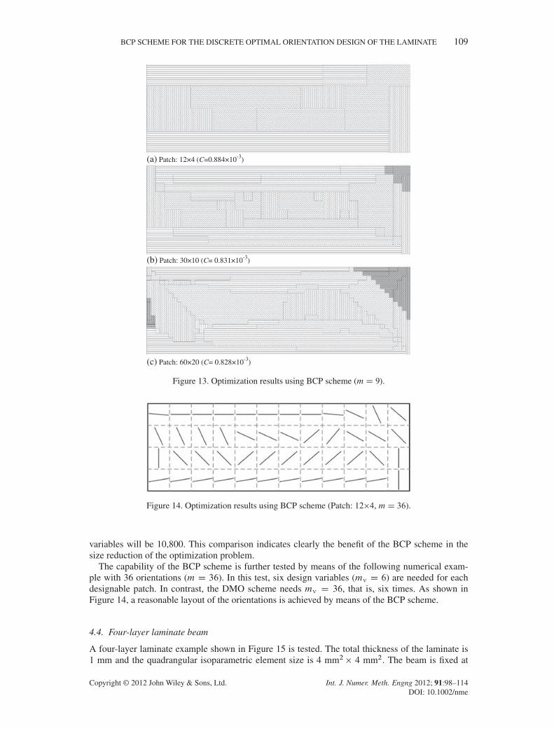
(a) Patch: 12×4 (C=0.884×10⁻³)
(b) Patch: 30×10 (C= 0.831×10⁻³)
(c) Patch: 60×20 (C= 0.828×10⁻³)
Figure 13. Optimization results using BCP scheme (mD 9).
Figure 14. Optimization results using BCP scheme (Patch: 12�4, mD 36).
variables will be 10,800. This comparison indicates clearly the benefit of the BCP scheme in thesize reduction of the optimization problem.
The capability of the BCP scheme is further tested by means of the following numerical exam-ple with 36 orientations (m D 36). In this test, six design variables (mv D 6) are needed for eachdesignable patch. In contrast, the DMO scheme needs mv D 36, that is, six times. As shown inFigure 14, a reasonable layout of the orientations is achieved by means of the BCP scheme.
4.4. Four-layer laminate beam
A four-layer laminate example shown in Figure 15 is tested. The total thickness of the laminate is1 mm and the quadrangular isoparametric element size is 4 mm2 � 4 mm2. The beam is fixed at
Copyright © 2012 John Wiley & Sons, Ltd. Int. J. Numer. Meth. Engng 2012; 91:98–114DOI: 10.1002/nme

110 T. GAO, W. H. ZHANG AND P. DUYSINX
Figure 15. Model of a four-layer laminate beam.
Layer 1
Layer 2
Layer 3
Layer 4
Figure 16. Optimization result of the four-layer laminate beam using BCP scheme.
one end and the uniform force is applied on the other end. The case of four candidate orientationsis considered.
The multilayer solid shell element in SAMCEF is adopted to construct the finite element modelof the beam and the element stiffness matrix related to each layer of each candidate orientation isextracted for sensitivity analysis.
Suppose both flanges have a symmetrical fiber orientation layout. The optimization result anditeration history of the structural compliance are shown in Figures 16 and 17, respectively. Herein,only one flange is shown for clarity. Layer 1 is the inner layer and layer 4 the outer one. Obviously,the optimization iteration is quite stable and converges very quickly.
5. DISCUSSIONS
In this section, the influences of the bi-value coding parameterization and initial weights upon theoptimization results are discussed. It should be noticed that there exist some other alternatives for
Copyright © 2012 John Wiley & Sons, Ltd. Int. J. Numer. Meth. Engng 2012; 91:98–114DOI: 10.1002/nme

BCP SCHEME FOR THE DISCRETE OPTIMAL ORIENTATION DESIGN OF THE LAMINATE 111
Figure 17. Iteration history of the four-layer laminate beam with BCP.
Table VI. Alternative codes for sjkvalues (mv D 2, mD 4).
j
k 1 2 3 4
1 –1 1 –1 12 –1 –1 1 1
1x
Figure 18. Illustrations of the BCP scheme.
the coding of candidate materials in the BCP scheme apart from those listed above. Unlike Equation(9), one alterative rule for sjk is expressed as
sjk D
²1 imod > istep
2
�1 imod 6 istep2
(18)
with
istep D 2k
imod D
8̂<:̂j �
jj
istep
k� istep j �
jj
istep
k� istep ¤ 0
istep j �j
jistep
k� istep D 0
. (19)
For instance, the alternative coding is listed in Table VI for mv D 2 and the illustration isshown in Figure 18. Compared with the coding given in Table I, the positions of material 3 and 4are exchanged.
The optimization results of two tests are shown in Figures 19(a) and (b). Compared with the lay-outs given in Figures 6(c) and 12(a), the current solutions using codes specified in Table VI are alittle better and the corresponding orientation layouts are slightly different. For the square plate, the
Copyright © 2012 John Wiley & Sons, Ltd. Int. J. Numer. Meth. Engng 2012; 91:98–114DOI: 10.1002/nme

112 T. GAO, W. H. ZHANG AND P. DUYSINX
Optimization results Principal stress direction
(a) Square plate under vertical force m=4 (C=1.162×10⁻⁴)
(b) Simply-supported beam ( m=4, Patch12×4, C= 0.845×10⁻³)
(c) Square plate under vertical force using continuation strategy (C= 1.093×10⁻⁴)
Figure 19. Optimization results using BCP codes in Table VI.
direction of the principal stress associated with BCP is also plotted in Figure 19(a). It is seen thatwith the set of discrete orientations, the optimal orientation in each patch globally agrees with theprincipal stress direction but the local differences do exist.
The comparison of BCP coding indicates that the use of a constant p might lead to differentdesigns depending on how the candidate materials are arranged in ordering. The continuation strat-egy with varying p from 1.5 to 4 is applied to test the effect of the penalization factor p. Theoptimization result is shown in Figure 19(c). It is obtained after 23 iterations and obviously betterthan that using constant p after 10 iterations, as seen in Figure 19(a). It can thus be concluded thatthe continuation strategy might lead to a better solution than the constant penalization, but could notensure the same result for different BCP codings.
In fact, more possibilities of the bi-value coding exist with the increase of the number of candidatematerials and it is hard to test all of them. Even this is done numerically; we cannot ensure whichchoice may lead to the global optimum because the widely used SCP lacks the ability to seek theglobal optimum for complicated optimization problems. Besides, the optimization problem may notbe a convex problem itself. For example, the considered objective function defined by the structuralcompliance is usually nonmonotonous and nonconvex for the considered design variables related tothe discrete orientations. Nevertheless, numerical tests indicate that the bi-value coding is able toyield satisfactory optimization results although the global optimum solution is not ensured by theefficient SCP algorithms. From another point of view, varieties of the bi-value coding might providedesigners more possibilities and options.
As to the setup of initial weights, a uniform value is adopted in all above tests as in the UMMIschemes presented in [12, 14]. It means that the initial value of each design variable is set to be
Copyright © 2012 John Wiley & Sons, Ltd. Int. J. Numer. Meth. Engng 2012; 91:98–114DOI: 10.1002/nme

BCP SCHEME FOR THE DISCRETE OPTIMAL ORIENTATION DESIGN OF THE LAMINATE 113
(a) xik=0.5 -45°)
C=2.445×10⁻⁴
(b) xik=-0.5 90°)
C=1.663×10⁻⁴
Figure 20. Influences of initial weights upon final orientations.
xik D 0 for each designable element or area. Geometrically, it corresponds to the origin of thebi-value coding scheme illustrated in Figures 1 and 18, respectively. Now, nonuniform initialweights are tested to illustrate their influences. Take still the square plate under vertical force asan example. Four orientations coded in Table VI are adopted. If the initial values of design variablesare set to be xik D 0.5, it is seen from the final layout given in Figure 20(a) that the material M4with the orientation of –45°is preferably selected by such nonuniform initial weights. Likewise, ifthe initial values of design variables are set to be xik D �0.5, the material M1 with the orien-tation of 90°is preferably selected in Figure 20(b). Obviously, the comparison of the compliancevalues indicates that both solutions resulting from nonuniform initial weights are worse than thatpresented in Figure 19(a). It is therefore preferable to use uniform weights at the beginning of theoptimization process.
6. CONCLUSIONS
A new parameterization scheme named BCP is proposed in this work to deal with the layout designof discrete material orientations for laminate composite. The theoretical expression of the BCP isconstructed in an explicit way for any number of materials. Because the involved number of designvariables depends upon the number of materials in logarithmic form, it is therefore advantageousover the existing DMO and SFP schemes to deal with large-scale problems.
Numerical examples show that the BCP scheme can produce a stable convergence and the solu-tion can easily be achieved with up to 36 material orientations. Furthermore, from the tests of theinitial values of design variables, it is concluded that the uniform initial weights with xik D 0 arepreferably selected in BCP to give rise to a satisfactory solution. A four-layer laminate example istested to illustrate that the proposed parameterization can easily be extended to multilayer problems.As an extension of the current work, it is believed that the BCP will open its proper applications inthe practical design of composite structures with a variety of objective functions and constraints inthe future.
ACKNOWLEDGEMENT
This work was supported by the National Natural Science Foundation of China (10925212, 90916027),973 Program (2012CB025904) and the Walloon Region of Belgium and SKYWIN (Aerospace Cluster ofWallonia) through the project VIRTUALCOMP (Contract RW-6293).
REFERENCES
1. Le Riche R, Haftka RT. Improved genetic algorithm for minimum thickness composite laminate design. CompositesEngineering 1995; 5(2):143–161.
2. Adali S, Richter A, Verijenko VE, Summers EB. Optimal design of hybrid laminates with discrete ply angles formaximum buckling load and minimum cost. Composite Structures 1995; 32(1-4):409–415.
Copyright © 2012 John Wiley & Sons, Ltd. Int. J. Numer. Meth. Engng 2012; 91:98–114DOI: 10.1002/nme

114 T. GAO, W. H. ZHANG AND P. DUYSINX
3. Todoroki A, Haftka RT. Stacking sequence optimization by a genetic algorithm with a new recessive gene like repairstrategy. Composites Part B: Engineering 1998; 29(3):277–285.
4. Thomsen J. Topology optimization of structures composed of one or two materials. Structural and MultidisciplinaryOptimization 1992; 5(1):108–115.
5. Sigmund O, Torquato S. Design of materials with extreme thermal expansion using a three-phase topologyoptimization method. Journal of the Mechanics and Physics of Solids 1997; 45(6):1037–1067.
6. Bendsøe MP, Sigmund O. Material interpolation schemes in topology optimization. Archive of Applied Mechanics1999; 69(9):635–654.
7. Sigmund O. Design of multiphysics actuators using topology optimization - Part II: Two-material structures.Computer Methods in Applied Mechanics and Engineering 2001; 190(49-50):6605–6627.
8. Yin L, Ananthasuresh GK. Topology optimization of compliant mechanisms with multiple materials using a peakfunction material interpolation scheme. Structural and Multidisciplinary Optimization 2001; 23(1):49–62.
9. Jung D, Gea H. Design of an energy-absorbing structure using topology optimization with a multimaterial model.Structural and Multidisciplinary Optimization 2006; 32(3):251–257.
10. Mei Y, Wang X. A level set method for structural topology optimization with multi-constraints and multi-materials.Acta Mechanica Sinica 2004; 20(5):507–518.
11. Lund E, Stegmann J. On structural optimization of composite shell structures using a discrete constitutiveparametrization. Wind Energy 2005; 8(1):109–124.
12. Stegmann J, Lund E. Discrete material optimization of general composite shell structures. International Journal forNumerical Methods in Engineering 2005; 62:2009–2027.
13. Lund E. Buckling topology optimization of laminated multi-material composite shell structures. CompositeStructures 2009; 91(2):158–167.
14. Bruyneel M. SFP - a new parameterization based on shape functions for optimal material selection: application toconventional composite plies. Structural and Multidisciplinary Optimization 2011; 43(1):17–27.
15. Pedersen P. On optimal orientation of orthotropic materials. Structural and Multidisciplinary Optimization 1989;1(2):101–106.
16. Pedersen P. Bounds on elastic energy in solids of orthotropic materials. Structural and Multidisciplinary Optimiza-tion 1990; 2(1):55–63.
17. Gea HC, Luo JH. On the stress-based and strain-based methods for predicting optimal orientation of orthotropicmaterials. Structural and Multidisciplinary Optimization 2004; 26(3-4):229–234.
18. Díaz AR, Bendsøe MP. Shape optimization of structures for multiple loading conditions using a homogenizationmethod. Structural and Multidisciplinary Optimization 1992; 4(1):17–22.
19. Cheng HC, Kikuchi N, Ma ZD. An improved approach for determining the optimal orientation of orthotropicmaterial. Structural and Multidisciplinary Optimization 1994; 8(2):101–112.
20. Svanberg K. A globally convergent version of MMA without line search. In First World Congress of Structural andMultidisciplinary Optimization. Pergamon Press: Goslar, Germany, 1995; 9–16.
Copyright © 2012 John Wiley & Sons, Ltd. Int. J. Numer. Meth. Engng 2012; 91:98–114DOI: 10.1002/nme