A bank-operated traveling-block cableway for stream ... · Paradiso, James J. 2000. A bank-operated...
41
USDA United States Department of Agriculture Forest Service Rocky Mountain Research Station Fort Collins, Colorado 80526 Stream Systems Technology Center General Technical Report RMRS-GTR-44 February 2000 A Ban k-Operated Traveling-Block Cableway for Stream Discharge and Sediment Measurements James J. Paradiso
Transcript of A bank-operated traveling-block cableway for stream ... · Paradiso, James J. 2000. A bank-operated...

USDA United States Department of Agriculture
Forest Service
Rocky Mountain Research Station
Fort Collins, Colorado 80526
Stream Systems Technology Center General Technical Report RMRS-GTR-44
February 2000
A Ban k-Operated Traveling-Block Cableway for Stream Discharge and Sediment Measurements
James J. Paradiso
klyon
OCR Disclaimer
Paradiso, James J. 2000. A bank-operated traveling-block cableway for stream discharge and sediment measurements. General Technical Report RMRS-GTR-44. Fort Collins, CO: U.S. Department of Agriculture, Forest Service, Rocky Mountain Research Station. 36p.
Abstract
Streams often present a challenge for collecting flow and sediment measurements on a year-round basis. Streams that can normally be waded become hazardous during seasonal flows, either endangering hydrographers or precluding data collection completely. A hand-operated cableway permits the accurate and safe collection of discharge and sediment data from the stream bank. This system provides a low-cost, safe alternative to cable cars or operation from bridges during high runoff. This publication describes the construction and use of a cableway system. Included are figures describing parts and dimensions, installation methods, and field operations.
Keywords
Stream discharge measurements, current meter measurements, suspended sediment measurements, bedload measurements, bank-operated cableway
The Author
Jim Paradiso works for the Nez Perce National Forest as a hydrologist on the Salmon River Ranger District in Idaho. He received his degree in Natural Resources Management at Colorado State University.
Publisher
Rocky Mountain Research Station
Fort Collins, Colorado
February 2000
You may order additional copies of this publication by sending your mailing information in label form through one of the following media. Please send the publication title and number.
Telephone (970) 498-1 392
E-mail rschneiderQfs.fed.us
FAX (970) 498-1 396
Mailing Address Publications Distribution Rocky Mountain Research Station 240 West Prospect Road Fort Collins, CO 80526-2098
Cover drawing of the traveling-block cableway by J. VanDeWater.

A Bank-Operated Traveling-Block Cableway for Stream Discharge and Sediment Measurements
James J . Paradiso
Contents --
Introduction ................................................................................................................... 1
Equipment Needed ....................................................................................................... 2
.............................................................................................................................. Design 3
Other Designs in Use ................................................................................................. 5
Cableway Site Selection .............................................................................................. 6
........................................................................... Installation of Posts and Cableway 7
Cableway Calibration ................................................................................................... 9
Cableway Operation ................................................................................................. 10
Modifications ............................................................................................................... 13
...................................................................................................... Acknowledgments 14
Literature Cited ........................................................................................................... 14
Appendix A: Cableway Plans ................................................................................. 15
Appendix 9: Supplies and Suppliers ..................................................................... 29
Appendix C: Using the Bank-Operated Cableway ............................................ 31

A Bank-Operated Traveling-Block Cableway for Stream Discharge and Sediment Measurements
Land managers have a continuing need to measure streamflow and sediment, both in unaltered settings and for monitoring response to management activities. Collecting discharge and sediment data at high flows may be neglected in some situations. This may be due to safety considerations associated with wading, or due to a lack of bridges or other available structure crossing the stream. A hand-operated cableway with traveling block system has been used by the Nez Perce National Forest since 1977. These installations allow hydrographers to safely collect streamflow and sediment data during high flow conditions. Operated from the bank, this cableway system provides a safe, low-cost, and effective method t o acquire year-round measurements.
As river stage rises, safety of the hydrographer who collects data becomes an increasing concern. The common rule-of-thumb is t o avoid wading in streams when the product of the depth (in feet) and the water velocity (in feet per second) exceeds 10. The use of temporary bridges and platforms can reduce the risk of an accident occurring during in-stream measurements, but at the same time it may provide forest visitors with a hazardous setting. of these situations.
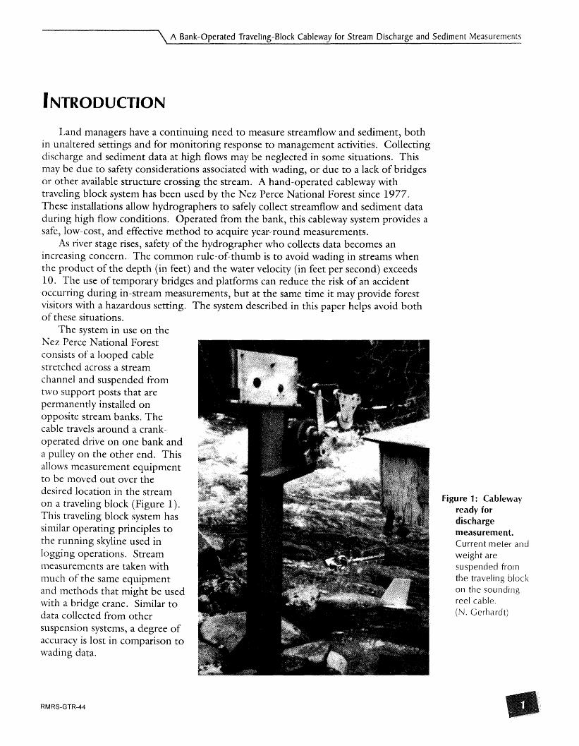
The system in use on the Nez Perce National Forest consists of a looped cable stretched across a stream channel and suspended from two support posts that are permanently installed on opposite stream banks. The cable travels around a crank- operated drive on one bank and a pulley on the other end. This allows measurement equipment to be moved out over the desired location in the stream on a traveling block (Figure 1). This traveling block system has similar operating principles to the running skyline used in logging operations. Stream measurements are taken with much of the same equipment and methods that might be used with a bridge crane. Similar to data collected from other suspension systems, a degree of accuracy is lost in comparison to wading data.
The system described in this paper helps avoid both
Figure 1 : Cableway ready for discharge measurement. Current meter and weight are suspended from the traveling block on the sounding reel cable. (N. Gerhardt)

A Bank-Operated Traveling-Block Cableway for Stream Discharge and Sediment Measurements
The system is generally applicable to streams less than 100 feet wide. This limitation is controlled by the cable length of the sounding reel used. Present installations on the Nez Perce National Forest are on 50-60 feet wide streams. Recent peak measurements recorded on these streams were a discharge of about 990 cfs (Rapid fiver, 5/16/96) and a velocity of 9.2 fps (Little Slate Creek, 5/16/97).
While hand-operated cableway equipment described in this publication was not developed by the Nez Perce National Forest, its documentation is obscure. The U.S. Bureau of Reclamation's Water Measurement Manual ( 1967) contains a one paragraph description and photo of a similar cableway in operation, but little more. The British Department of the Environment, Water Data Unit (1978), has published a review of three portable winches designed for use with portable or permanent cableways. Described as portable, these winches weigh 80 to 160 pounds.
Mechanical drawings of cableway systems from the Lolo National Forest (1979) and the Montana Department of Natural Resources and Conservation (1976) are reproduced here, with slight modifications.
Similar bank-operated cableway systems are in use across the country. A short summary of four of these systems is included for completeness. Each has advantages and disadvantages in ease of installation, ease of use, portability, and cost. The evaluation of these other systems is by no means comprehensive, as the author has no first- hand experience with their operation.
The cableway is constructed of parts manufactured at a machine shop, with additional parts from a hardware store. Installation requires readily available construction supplies including concrete, cable, cable clamps, and turnbuckles.
The cableway parts requiring fabrication are described in detail in construction plans contained in Appendix A. The posts and pulleys are steel and a majority of the remaining parts are made of aluminum to resist rust.
Measurements are taken with standard stream gaging or sediment sampling equipment. Operation requires a sounding reel to raise and lower the equipment. Cable-suspended equipment could include a current meter with sounding weight, bedload sampler, or suspended sediment sampler, depending on the data desired. A list of suppliers and estimated costs is contained in Appendix B.

\ A Bank-Operated Traveling-Block Cableway for Stream Discharge and Sediment Measurements
The cableway consists of six parts (Figure 2). An upright steel post is installed on each bank. On the shore with easy access, a pulley-drive housing is mounted atop the post. On the far shore the post supports a pulley, the tailhold. Operated with a hand crank, the pulley-drive controls the movement of a looped cable that is stretched between the posts. A traveling block rides on the upper cable loop and is attached to the lower cable loop. Suspended from this traveling block, the hydrographers' equipment may be positioned and operated anywhere in the cross section.
Figure 2: Schematic of the cableway system with sounding reel and current meter in use. ( 1 ) near post with pulley drive housing, (2) sounding reel, (3) cableway cable, (4) sounding reel cable, (5) traveling block, (6) current meter, and (7) tailhold on far post. (J. VanDeWater)

A Bank-O~erated Travelina-Block Cablewav for Stream Discharge and Sediment Measurements /
A standard sounding reel, such as an A-55 or B-56, is also attached to fittings o n the near post (Figure 3) . The cable from the sounding reel is used to suspend the measuring equipment, such as a current meter. The cable is supported by the lower pulley of the traveling block. Using the sounding reel, the equipment may be raised and lowered as needed for data collection. Thus, the horizontal position of the current meter is controlled by the cableway crank, while the vertical movement is controlled by the sounding reel.
Figure 3: Key components of the cableway. Traveling block, sounding reel, and crank-pulley mechanism. (N. Gerhardt)

\ A Bank-Operated Traveling-Block Cableway for Stream Discharge and Sediment Measurements
A lighter version cableway made with a boat winch is in use on the Clearwater and Idaho Panhandle National Forests in North Idaho. This installation is very inexpensive. A boat winch may be purchased for as little as $40.00 to replace the crank-pulley drive housing. The system is often attached to trees, rock or other available structures, reducing setup time. (Brooks Beegle, Clearwater National Forest, Orofino, ID)
A completely portable system has been used by the U.S. Forest Service Pacific Southwest Experiment Station. Instead of permanent posts, tripods with guylines support the equipment. In this way the entire cableway can be moved to temporary, remote locations. I t is set up prior to high flows and then left in place for the season. (Tom Lisle, Redwood Sciences Laboratory, Arcata, CA)
A simple variation of our cableway is built to a U.S. Geological Survey (USGS) design, and marketed by a hydrological equipment supplier. The "USGS Bank- - -
Operated Cableway" uses a static line to suspend the equipment from the traveling block. A hand-operated tow cable is strung beneath the static line on two pulleys and is used to position the traveling block and equipment. A sounding reel controls the vertical motion of the equipment, similar t o our design. One advantage of this design is the ease of using guy-lines on the posts, providing a more stable system. A 100-foot span version of this system generally sells f i r less than $2,500, not including the sounding reel or measurement equipment. (fickly Hydrological Company, Columbus, O H . )
The U.S. Geological Survey in Washington has designed a cableway that works closely with the B-56 sounding reel. Instead of being separate, the cableway control unit attaches directly to the sounding reel without modification. I t provides vertical or horizontal control with the one reel handle. During horizontal positioning, the sounding cable is simultaneously controlled, malung this job easier and faster. This system, as well as a version of the one discussed in this paper, is presently available from fickly Hydrological Company. (John Bowldy, U.S. Geological Survey, Tachoma Field Office, WA.)
For larger installations, double drum winches are available. The cableway towers and main cable are a heavy-duty version of the design described in this paper and cost about $10,000. Double drum winches start at $7,500, replacing the need for a B-reel. One manufacturer is Ot t Messtechnik, Germany. These systems are available through fickly Hydrological Company and Scientific Instruments of Milwaukee.
A Bank-Operated Traveling-Block Cableway for Stream Discharge and Sediment Measurements /
Site selection depends both on the qualities needed for a good discharge or sediment measurement and on factors affecting the installation and operation of the cableway. Buchanan and Somers (1969) discuss selection of discharge measurement sites. Other measurements to be taken may have additional requirements, such as the channel substrates and their effect on bedload measurements. A discussion of site factors that can affect the operation and strength of the cableway follows.
Substrates may affect the stability of the posts and resulting cableway strength. Rock or boulder sites will provide a more secure foundation for the posts than sands or gravel. Post stability can be increased with additional concrete, anchors, and bracing. Posts may be modified and bolted directly to solid rock.
A person experienced with the channel and its historic stages can provide valuable knowledge and insight. Consider the 100-year floodplain to protect the posts from possible flood damage. The approach to the site may become more difficult at high- water, but access is only needed to one side to operate the cableway. The posts will need to be positioned so the cable is perpendicular t o the water flow.
The distance between the posts may affect the operation of the cableway. Span width is limited by the length of cable on the type of sounding reel used and by the sag of a weighted cable. The A-55 sounding reel comes equipped with 75 feet of cable, while the B-56 reel may be equipped with either 11 5 or 144 feet of cable. As the span approaches the length of the sounding cable, the distance the posts are set back from the high water mark and the height above the high water mark may become important factors in determining post placement.
The optimal post position results in the cable being at a height of six feet above the water level during the use period, which is commonly high flows. The water level at bankfull is a good starting point, with consideration given to how much higher peak flows might be. A terrace, or abandoned floodplain, may provide a good site. Generally, the higher the cable is above the water, the less the effort that will be needed to horizontally position the equipment at the desired location. Posts set just above high water will work; they just require more effort and coordination during operation. A weighted cable commonly sags one or two feet and even more for long spans. In borderline conditions, computation of cable sag by a structural engineer may be beneficial.
The position of the cable relative to water levels is especially important to consider in rivers used for recreational boating. Cables need to be high enough to avoid creating dangerous situations for recreational users. Appropriate considerations are a function of the type and amount of use and may include measures such as signing or posting outlooks during measurement periods.
A work area with good footing will ease operation and improve safety at the site. The cableway is operated from behind and to the sides of the head block post. A level space between the head block post and the stream is desirable so measurement equipment may most easily be transported and attached to the cableway. Avoid placing the cable where you will have to duck under it to access the river's edge, either when using the cableway or during other times of the year. A trail may be needed to move equipment from your vehicle to the cableway.
\ A Bank-Operated Traveling-Block Cableway for Stream Discharge and Sediment Measurements
Installation should occur when the river can be waded. On-site installation time for one person is approximately four hours to set posts and two hours t o install the pulley mechanisms, cable and carriage. The use of concrete will require a drying period between each of these steps. For those less experienced in construction projects, installation time may double.
The posts must be firmly anchored. They need to be set plumb, at a convenient work height, and so the pulleys are level and aligned with each other. Forces applied to the posts can quickly reach high levels. Rocky substrates provide the most secure foundation. Most commonly, the post is set in a hole and filled with concrete for a secure footing. More concrete is needed for sites with little rock. As little as two bags of concrete might be used, but a poor site might require a cubic yard or more. A tie- back with anchor(s) may be used to support the tailhold but should be avoided at the pulley housing end, where it may interfere with operations.
Post installation:
+ The top of the head block post should be installed at a height of about four feet, allowing the cranks to be operated easily by both tall and short persons. Set the tail post so its top is about nine inches above the top of the head block post. Align the posts so the pulleys will be directed towards each other, minimizing binding of the cable. Brace the posts until the concrete has dried.
+ Measure the distance between the posts for the cable.
+ Allow concrete to cure seven days or more, depending upon the type of concrete used.
Installation of the pulley mechanisms, cable and carriage:
+ Bolt the main pulley housing atop the near post and the tail pulley on the far post.
+ Attach a turnbuckle to each end of the center tie bar of the traveling block. Clamp the cable to one of the turnbuckles using a thimble and two clamps.
A Ban k-Operated Traveling-Block Cableway for Stream Discharge and Sediment Measurements /
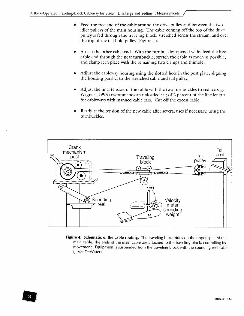
+ Feed the free end of the cable around the drive pulley and between the two idler pulleys of the main housing. The cable coming off the top of the drive pulley is fed through the traveling block, stretched across the stream, and over the top of the tail hold pulley (Figure 4).
+ Attach the other cable end. With the turnbuckles opened wide, feed the fi-ee cable end through the near turnbuckle, stretch the cable as much as possible, and clamp it in place with the remaining two clamps and thimble.
+ Adjust the cableway housing using the slotted hole in the post plate, aligning the housing parallel to the stretched cable and tail pulley.
+ Adjust the final tension of the cable with the two turnbuckles to reduce sag. Wagner (1995) recommends an unloaded sag of 2 percent of the line length for cableways with manned cable cars. Cut off the excess cable.
+ Readjust the tension of the new cable after several uses if necessary, using the turnbuckles.
Figure 4: Schematic of the cable routing. The traveling block rides on the upper span of the main cable. The ends of the main cable are attached to the traveling block, controlling its movement. Equipment is suspended from the traveling block with the sounding reel cable. (J. VanDeWater)
\ A Bank-Operated Traveling-Block Cableway for Stream Discharge and Sediment Measurements
Use of the line counter fitting described in the construction plans is not recommended. A means t o identify the horizontal location of the traveling block is needed, but previous use of the line counter on the counter pulley shaft (Appendix B, sheet 5, part 16) proved unreliable. Slipping of the cable resulted in inaccurate readings, and year-round exposure to the weather caused the counter to fail.
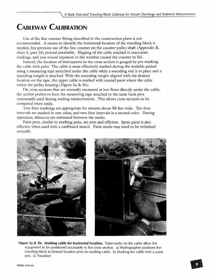
Instead, the location of instruments in the cross section is gauged by pre-marlung the cable with paint. The cable is most effectively marked during the wadable period using a measuring tape stretched under the cable while a sounding reel is in place and a sounding weight is attached. With the sounding weight aligned with the desired location on the tape, the upper cable is marked with enamel paint where the cable enters the pulley housing (Figure 5a & 5b).
On cross sections that are normally measured at low flows directly under the cable, the author prefers t o have the measuring tape attached to the same bank pins customarily used during wading measurements. This allows cross sections to be compared more easily.
Two-foot markings are appropriate for streams about 50 feet wide. Ten-foot intervals are marked in one color, and two-foot intervals in a second color. During operation, distances are estimated between the marks.
Paint pens, similar to marking pens, are neat and efficient. Spray paint is also effective when used with a cardboard stencil. annually.
Paint marks may need to be refreshed
Figure 5a & 5b: Marking cable for horizontal location. Paint marks o n the cable allow the equipment to be positioned accurately in the cross section. a) Hydrographer positions the traveling block at desired location prior to marking cable. b) Marking the cable wi th a paint pen. (I. Paradiso)
A Bank-Operated Traveling-Block Cableway for Stream Discharge and Sediment Measurements
Discharge measurements and sediment sample collections are taken using standard equipment and techniques (Buchanan and Somers, 1969). The operation protocols used on the Nez Perce National Forest are included in Appendix C.
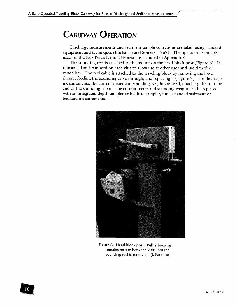
The sounding reel is attached to the mount on the head block post (Figure 6). It is installed and removed on each visit to allow use at other sites and avoid theft or vandalism. The reel cable is attached to the traveling block by removing the lower sheave, feeding the sounding cable through, and replacing it (Figure 7). For discharge measurements, the current meter and sounding weight are used, attaching them to the end of the sounding cable. The current meter and sounding weight can be replaced with an integrated depth sampler or bedload sampler, for suspended sediment or bedload measurements.
Figure 6: Head block post. Pulley housing remains on site between visits, but the sounding reel is removed. (J. Paradiso)

\ A Bank-Operated Traveling-Block Cableway for Stream Discharge and Sediment Measurements
Figure 7: Attaching the sounding cable to traveling block. The sheave is removed and replaced to attach the cable prior to use. (B. Beegle)
The equipment is positioned at the partial section to be measured, using the marlungs on the cable. This requires operating both the cableway and reel handles, feeding line out with the sounding reel as the block is moved out with the cableway crank (Figure 8). Coordination is required to move the equipment into position, turning the two cranks simultaneously. When using 50 pound or heavier sounding weights, setting and retrieving sampling equipment from wide streanls may be slow and tiring. The operation is best shared by two persons worlting in unison, each on one of the control handles.
Figure 8: Hydrographer's view. Operation o f the two handles needs to be coordinated to move the equipment. (N. Gerhardt)

A Bank-Operated Traveling-Block Cableway for Stream Discharge and Sediment Measurements
Safety precautions need to be taken when operating the cableway. High flows and moving debris can apply large stresses to the components of the system. The ratchet pawl locking the horizontal location of the traveling pulley must operate freely. If it sticks in the up position while moving the main cable, the handle may spin wildly, with force, when released.
The vertical placement, or depth, of the current meter is set with the depth indicator of the sounding reel. The depth indicator is set to zero as the bottom of the weight (or the current meter cups) touches the water surface. It is read again when it touches the stream bottom. The meter is then raised to the appropriate depth, accounting for the distance separating the meter and the weight.
The horizontal angle of the current meter is hard to assess and must be estimated from the shore.
During peak flows, high water velocities and floating debris can further complicate operations. Erratic movement of the samplers can be reduced by moving them quickly through the faster, upper levels of the stream. Large boulders can interfere with the placement of samplers, and some will cause the samplers to tilt and ruin the sample. These locations need to be avoided. Watch upstream for floating debris, being prepared to lift the sampler to avoid being snagged.
Transit rates for depth-integrated suspended-sediment measurements can be calculated using revolutions of the sounding reel. The A-5 5 reel has a drum circumference of 1 foot, the B-56 reel a circumference of 1.5 feet. Thus when using a B-56 reel, the handle is turned once each second for a 1.5 fps transit rate.
Bedload samples collected with a Helly Smith sampler involve the same challenges for the operator as any cable system. High flows can cause rapid erratic movement as the sampler is lowered through the water column. Fast velocities near the surface will pull the sampler downstream. As the sampler passes into the slower velocities near the bottom, it will swing in under the suspension point, potentially scooping bottom materials and contaminating the sample. The operator must learn to lower the sampler to avoid this. While experience will be the best teacher, in general the sampler is lowered quickly through the fast water, or to about 2/3 of the depth. Then it is lowered more slowly in the deeper, slow water, allowing the sampler to swing back upstream. Finally, it is lowered the last increment to the bottom.
Following use, the sounding equipment, including the sounding reel, is removed from the site. The traveling block may be positioned near the middle of the stream and the cable locked in place with a cable clamp, or a chain and padlock may be used to lock the traveling block to the main housing.

A Bank-Operated Traveling-Block Cableway for Stream Discharge and Sediment Measurements
In constructing the pulley housing, block and tailhold, consider the needs of your situation and make modifications when appropriate. Some suggestions below are untried. The described parts are referenced by numbers as they appear on the construction drawings in Appendix A. These suggestions include:
1. Weld the sides of the housing, reducing the time and expense of drilling and tapping for fastening screws (7).
2. Eliminate the idler pulley (9) and/or the counter pulley (10) in the housing. This may result in the cable slipping, but aircraft grade cable may help reduce this. The groove in the drive pulley (8), sounding sheave (52), and tail sheave (60) must match the cable diameter.
3. One-eighth inch cable has been used successfully for the applications on the Nez Perce National Forest. Larger streams may require a heavier cable. A structural engineer can determine the forces exerted for a system. The brealung strength of the sounding cable is considered in designing the load applied to the system, reflecting the possibility of snagging floating debris during measurements. The breaking strength of the B-56 sounding cable is 1,600 pounds. For a more complete discussion, see Wagner (1995).
4. A cover for the pulley housing may be desirable to prevent debris, such as conifer needles, from accumulating in the mechanism, and also deter vandalism. An open-ended box that slips over the pulley housing from the top would prevent the handle from being turned. Attachments to hold a padlock beneath the cable would secure this cover to the housing.
5. With no line counter, the counter shaft (16) could be simplified by eliminating the portion of the counter shaft that protrudes from the right housing side.
6. Modify the cable sheaves (49) of the traveling block assembly. The sheave on the near side bears most of the weight and resulting stress and wear. A 3/8" ID ball bearing could replace the bronze bearing (51) specified. The cable pulley (50) would need t o be machined to accept the ball bearing.
7. The design of the traveling block assembly (35) could be modified. As pictured in figure 7, the bottom spacer (43) has been dropped, and the sides simplified. Parts (37), (38), (45), (46), and (47) have been combined into one piece. The back (36) is modified and similar to the front plate.
8. A further simplification of the traveling block assembly (35) is t o eliminate one of the cable sheaves (49). The remaining sheave would be positioned in the middle of the center tie bar (40). Two plates would hold the single cable sheave above and the sounding sheave below.
9. One of the 3/8" x 16" turnbuckles could be eliminated. This cost-saving measure would reduce the range of adjustment available and may make it difficult to tighten the cable.

A Bank-Operated Traveling-Block Cableway for Stream Discharge and Sediment Measurements / .
Thanks to those who provided their technical knowledge and insights on cableways: Brooks Beegle, John Bowles, Lawrence Clark, Jim Frasier, Thomas Lisle, Nick Gerhardt, Gail Howard, Mike Rickly, Skip Rosquist, Sandra Ryan, Ron Torretta, and Fred Warner. Thanks to Lois Peterson of the Nez Perce National Forest for redrawing the construction plans, John Potyondy and Larry Schmidt of the Stream System Technology Center for malung this paper a reality, as well as their technical assistance, encouragement and patience, and Karen Mora, Carol LoSapio, and Joyce VanDeWater for help with publication and graphics.
Buchznan, Thomas J. and William Somers. 1969. Discharge Measurements At Gaging Stations. Techniques of Water-Resources Investigations. U.S. Geological Survey. Book 3, Chap. A8.
Bureau of Reclamation. 1967. Water Measurement Manual: A Manual Pertaining Pri- marily To Measurement of Water For Irrigation Projects. U.S. Department of the Interior.
Great Britain, Dept. of the Environment, Water Data Unit, 1978. Portable current meter cableways and winches. Report of the Instruments and Methods Observation Group Technical Memorandum No. 17, Reading [England], 12 p.
Montana Department of Natural Resources and Conservation. 1976. Traveling Block Cableway (Drawing). Approved by &chard Bandy, Chief. Engineering Bureau, Water Resources Division.
Wagner, Russell. 1995. Stream- Gaging Cableways. Technical Water-Resources Investi- gations. U.S. Geological Survey. Book 3, Chap. A2 1 .
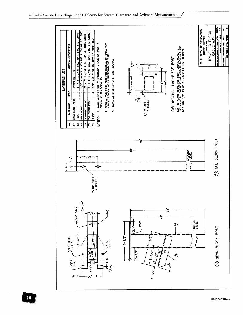
U.S. Department of Agriculture. 1979. Traveling Block Cableway (Drawing). Drawn by Lassila. Lolo National Forest. Missoula, Montana.

\ A Bank-Operated Traveling-Block Cableway for Stream Discharge and Sediment Measurements -
A full-sized set of scaled AutoCAD plans ( * .dwg format) as well as standard graphics files ( * .tif format) for printing are available for downloading from the internet from the Stream Systems Technology Center web page at http://www.stream.fs.fed.us.

IND
EX
TO
SHEE
TS
I
I DE
SCRI
PTIO
N O
F S
HE
D
1 1 C
OVE
R SH
EET
I 2
1 CAB
LE W
AY H
OU
SIN
G
3 I S
IDES
. B
OlT
OM
. TO
P AN
D RE
AR S
PAC
ERS
DR
NE
, ID
LER
AND
COUN
TER
PULL
EYS
SHAF
TS A
ND
WEA
VES
PLAT
ES A
ND
SHEA
VE
VI
78
6A
8B
-
TR
AV
EL
ING
BL
OC
K
PLAT
E.
PULL
EYS.
E4R
AND
BL
OCK
-
VER
SIO
N B
TRA
MU
NC
BLO
CK
ASSE
MBL
Y -
VER
SIO
N A
TRA
MU
NG
BLO
CK
ASSE
MBL
Y - V
ERSI
ON
B
CA
BL
E W
AY
U.
S.
DE
PT.
O
F A
GR
ICU
LTU
RE
I FO
RES
T SE
RVl
CE
TRAV
ELIN
G
BLO
CK
C
AB
LE W
AY
PfJ
EA
SO
ll U
TE:
9/9
7
WU
FfR
CE
wn. FO
RES
T
I M
ATE
RIA
LS L
IST
1
I NO
. I
PA
RT
WE
I RW
D.
I MT
ERIAL
-DES
CRIPT
ION 1
1
1 CAB
LE W
AY
HO
USI
NG
( 1
2 1 L
EF
l SI
DE
11
I 3
1 RIG
HT
SID
E 1
1 PA
RTS
2-3
0
PAR
T 2
PAR
T 3
4 1 B
OTT
OM
(
1 I PA
RT
4
5 1 T
OP
SPAC
ER
1 1
PART
5
1 6
1 REA
R S
PAC
ER
I 1
1 PAR
T 6
1
7 1 S
CR
M
14
8 1 D
RM
PU
LLEY
1
1
12
I DRM
sw
I
13
1 BEA
RIN
G
2
14
IIMER
SW
I
1
15
l BEA
RIN
G
2
1/4'
-20
NC
X 5
/B
LC.
SO
CK
fl H
D w
-~C
RE
W
PAR
T 8
PAR
T 9
PAR
T 10
,984
3'
BOR
E X
1.85
04-
00 X
.4
724"
WID
E Rh
DL4L
WI
NG
WIT
H T
WO
SW
S
FAFN
IR
1910
5PP
PAR
T 12
.472
4'
BOR
E X
1.10
24-
OD
X .3
150'
W
IDE
RA
DU
L
BEAR
ING
WIT
H T
WO
SEAL
S FA
FNIR
1
91
01 P
P
PAR
T 14
I
5693
" BO
RE
X 1.
3780
" 00 X
3
93
7 W
IDE
RA
DIA
L
BEAR
ING
WIT
H
TWO
SEAL
S FA
FNIR
19
103P
P
16
17
18
19
25
28
1 S
CREW
I
I
I I/<
X
l/2'
LC.
SOCK
ET
HD
SH
OU
LDER
SC
REW
29
I W
ASHE
R I
1 I 1 /4
" FE
ND
ER W
ASH
ER 9
/32'
ID
X
1 - 1 /4
" O
D
X 1 /I
6"
ST.
26
27
30
1 S
CREW
I
1 I1
/4"-
20
NC
X
518"
LC
. SO
CKE
T H
D
CA
P S
CR
EW
76
1 KEY
I
I
I l/<
SO
. X
1' LC
. R
WN
D B
OTH
EN
DS
KEY
CO
UN
TER
S
W
KEY
KEY
HAN
DLE
KE
Y
1
I
- I
1 11
18-3
2 N
C
X 1/
4'
LC.
SOC
KET
SET
SCRE
W
1
SPR
OC
KET
PAW
L
@ C
AB
LE W
AY
HO
US
ING
1 2 1 1 1
PAR
T 16
1/4'
SO
. X
1/-l
/4"
LC.
RW
ND
BO
TH
END
S K
EY
3/16
" SO
. X
I/- 1
4"
LC.
RO
UN
D B
OTH
EN
DS
KE
Y
PA
RT
S20
-24
3/16
" SO
. x
7/
~
LC.
RO
UN
D O
NE
EN
D K
EY
1 1
7
PAR
T 26
PAR
T 2
7
U.
S.
DEP
T.
OF
AG
RIC
ULT
UR
E
FOR
ES
T S
ER
VlC
E
RE
WN
OM
TRA
VE
LIN
G
BLO
CK
C
AB
LE
WAY
CR
AW
BY:
WS
LA
D
ATE
8/7
9
LOLO
wn. fo
ncsr
R
mrw
m P
mR
sm
DAT
E: 9
/97
NU
~n
cc
wn. F
aw
n
m
2 OF 1
1

I M
ATE
RIA
LS L
IST
I
3
1 RIG
HT
SlD
E 1
1 1 1 /
2 X
9
X
13-3
/4
LON
G 6
061 -
TG
KU
U R
AT
4
1 BO
rrO
U
I 1
1 1/2
X
1 - 1/
2 X
17
-3/8
LO
NG
606
1 -T
G
KU
U F
IAT
NO
.
2 5
TOPS
P PAC
ER
I 1
11/2
X
1-1
/2X
3L
ON
C6
06
1-T
CM
UM
F
UT
6
I Bo
llOU
SPA
CER
I
1 1 1
/2
X
1 - 1 /2
X
6- 1
/2
LON
G 6
061 -
TC
MU
M F
IAT
@ L
EFT
S
lDE
PART
NAM
E
LEFT
SI
DE
@)
TOP
S
PA
CE
R
SCAL
E:
1/2"
=
1"
@
BO
TTO
M
REQ
'D.
1
U.
S.
DEP
T.
OF
AGR
ICU
LTU
RE
I
FOR
ES
T SE
RV
ICE
UAT
ERU
L-D
ESC
RIP
TKjN
1/2
X 9 X
13
-3/4
LO
NG
606
1 -TC
AL
UM
R
AT
I &
UO
N%
-
TRA
VE
LIN
G
BLO
CK
@
R
EAR
S
PA
CE
R
@ R
IGH
T S
lDE
C
AB
LE
WAY
W
AW
Nm
USg
U
MT
E.8
/79
1-
@ D
RIV
E
PU
LLE
Y
@ I
DLE
R
PU
LLE
Y
MAT
ERIA
LS L
IST
NO
. I
PAR
T W
E I R
EQT)
. I MATERIAL-DESCRIPTION
--I
t Nol
I0 S
ea*
@ C
OU
NTE
R
PU
LLE
Y
U.
S.
DEP
T.
OF
AG
RIC
ULT
UR
E FO
RES
T SE
RVl
CE
I R
Ea
oN
k
--
TRA
VE
LIN
G
BLO
CK
iao
run. F
CI?ES
T
Rm
rUm
* pE
mK
on M
TE
9/97
NU
AR
CE
run. F
OR
M
4 OF 1
1

@ D
RIV
E
SH
AFT
@
IDLE
R
SH
AFT
14
16
@ C
OU
NTE
R
SH
AFT
IDLER
w
I 1
I3/4-
OD
X 2-l/8"
LC. 1045 C
R S
WN
G R
OU
ND
COUN
TER
SnAFl
I 1
11' O
D X 3-3/8"
LC. 1045 C
R S
HM
llNG
RO
UN
D
U.
S.
DE
PT.
O
F A
GR
ICU
LTU
RE
FORE
ST S
ERVl
CE
REO
DW
ONE
TRA
VE
LIN
G
BLO
CK
C
AB
LE
WAY
D4
AW
BY:
USSU
M
IE:
8/79
L
ao
MR. ~
OR
ES
I
Raw
uwK
PnE
Rso
n M
lE 9
/97
rU P
ERC
E MR. FO
RES
T
5 of 1 1

MA
TER
IALS
LIS
T
NO
. PA
RT
NAM
E
19
20
21
22
@ P
AW
L
REO
'D.
UATE
RIAL
- D
ESC
RIP
TIO
N
--(
1/4*
m
NE
OFF
HA
NM
E
RO
UN
D
ARM
HA
NM
E
25
24
26
27
@ H
AN
DLE
1 1 1 I
BOLT
PIN
SPR
OC
KET
PAW
L
@ S
PR
OC
KE
T
1 1 1 1 -
--
3/8"
-
16
NC
RO
UN
D H
D.
CARR
lACE
BO
LT
1/16
" DI
A.
X 3/
4"
LC.
STEE
L RO
LL P
IN
12 P
ITC
H.
30 T
OO
TH.
14-1
/2*.
2-
1/2
PD.
7/8
BORE
KW
Y &
SS
1/2
X 3/
4"
BRAS
S FI
AT
U.
S.
DEP
T.
OF
AG
RIC
ULT
UR
E I
FOR
EST
SE
WC
E
PAR
TS 2
0 -
24
1-1/
2" W
X 7
/g
LG.
1/2"
X
1-l
/r
X 8
-3/8
LG.
WOO
D
RE&-&
--
TRA
VE
LIN
G
BLO
CK
C
AB
LE
WAY

7
MA
TER
IALS
LIS
T I
I NO
. I
PART
N
AU
E I R
EQ'D
. I
UAT
ERIA
L-D
ESC
RIP
TIO
N
I 3
6
37
38
39
40
43
@ B
OTT
OM
P
LATE
BAC
K
TOP
PIA
TE
BO
rrO
U P
LATE
45
46
47
49
( CAB
LE S
HEA
VE
I 2
I PAR
TS 5
0-51
50
1 CAB
LE P
ULL
EY
I 2
12
-3/b
D1
A. X
3/4"
LC
. 60
61-T
6 M
UM
. W
OY
RO
UN
D
TOP
SPAC
ER
CEN
TER
nE
BA
R
BOTT
OM
SPA
CER
1 1 1
PU
TE
STO
P
SCRE
WS
@ B
AC
K
1/4"
TH
ICK
6
06
1 -T
M1
AL
UM.
ALLO
Y PL
ATE
1/4"
X
3"
X 7
- 1
/T
LC.
60
61
-T65
11
ALU
M A
LLO
Y RE
CT.
1 /4'
X 2
- 1 /7
X 4
-5/8
LC
. 8
06
1 -1
651
1 AL
UM
K
LOY
RE
CT.
1 1 1
51
@ T
OP
S
PA
CE
R
3/4"
X
1' X
2-3/
4'
LC.
6061
-165
1 1
ALU
M.
ALLO
Y RE
CT.
3/4-
x
1"
x 8'
LC.
w6
1-~
6s
i i M
UM
. AL
LOY
REC
T.
1 /1 X
1' X
2- l/f L
C.
6061
-T65
11
ALU
U.
ALLO
Y RE
CT.
1 1 2
@ C
AB
LE
SH
EA
VE
1/4"
X
2-
1/r
X
2- 1
/2"
LC.
6061
-765
1 1
ALUM
. AL
LOY
RECT
.
l/Z
X
1"
X 2
-l/T
LC
. 60
61-T
6511
AL
UM
. M
LOY
REC
T.
48 -
32
NC
X I" LC
. FL
AT
HD
. SO
CKE
T C
AP
SCRE
W
- -
BEAR
ING
( 9/3
7
MnL
L - 2
HOLE
S
U.
S.
DE
PT.
OF
AGRI
CULT
URE
FOR
ES
T S
ER
VIC
E
3
DRAW
N Bv
. U
SgU
M
tE.
8/79
I S
l€E
E
37
5 I
D X
5
03
OD
X 1
LC.
OIL
- IM
PREG
NAT
ED
BR
ON
ZE B
EAR
ING
" O
IUT~
&
A-5
2
1 - 1
1 O
R EQ
UAL
@
CE
NTE
R
TIE
B
AR
@
C
AP
@
BO
TTO
M
SP
AC
ER
MA
TER
IALS
LIS
T
NO
. I
PAR
T W
E
I REO
'D.
I W
TER
iAl-
DE
SC
RIP
TDN
SOU
ND
ING
PU
UE
Y
ANCH
OR
EAR
3/4"
X
1' X
8"
LG.
6061
T6
ALUM
.
EYE
BOLT
l/
4*
X 1"
W
ITH
LOC
K
NUT
b2
-4
@ S
IDE
P
LATE
@ S
OU
ND
ING
P
ULL
EY
@ C
AR
RIA
GE
P
ULL
EY
( D
RIL
L &
TA
P -
FoR-
1/4"
0 EY
E BO
LT
W/L
OCK
N
UT
@ A
NC
HO
R
BA
R
@ S
PA
CE
R
BLO
CK
DE
PT.
O
F N
ATU
RA
L R
ES
OU
RC
ES
A
ND
C
ON
SER
VATI
ON
W
ATER
RtfO
UR
CE
f D
M90
11,
ENG
lMZR
llG B
LlR
W
TRA
VE
LIN
G
BLO
CK
C
AB
LE
WAY
USBR
. U
SM
FS. M
n#:
NU
PER
CE MR. W
ST

@ T
RA
VE
LIN
G
BLO
CK
A
SS
EM
BLY
MAT
ERIA
LS L
IST
NO.
PAR
T N
AUE
REO
'D.
MAT
ERIA
L-D
ESC
RIP
TIO
N
1 3
5
1 TRAV
ELIN
G B
LOC
K I
1 1 PA
RTS
36
- 5
5
I 3
6
!BA
CK
1
1 I 1/
4'
THIC
K 60
61-T
651
ALU
M.
AU
OY
PL
ATE
37
1 T
OP
PLAT
E I
1 It
/*'
X 3
' X
7-1
/2
LG.
6061
-T65
11
ALU
M
ALLO
Y R
ECT.
38
BO
TT
G
PU
T€
I
1/4'
X
2-l
/2"
X 4
-S/8
" LC
. 60
61 -T
6511
AL
UM
ALL
OY
RECT
.
39
TO
P SP
ACER
1
3/4'
X
1"
X
2-3/
4"
LC.
6061
-T6
5ll
AL
UM
. A
UO
Y R
ECT.
40
CEH
TER
TIE
BA
R 1
3/4'
X
1' X
8'
LC.
6081
-T65
11
ALU
M.
ALLO
Y RE
CT.
41
BOLT
S 6
1/4-
-
20
NC
X
1 -3/
4'
LG.
HEX
H
D C
AP S
CREW
42
N
UTS
6
1/4"
-
X 20
NC
FIB
ER L
OC
K H
EX
NU
T
43
BO
TTO
M S
PAC
ER
1 l/2
" X
1' X
2-1
/Z
LG.
6061
-T65
11
ALU
U.
ALLO
Y R
ECT.
44
C
AP
1 P
AR
TS
45
- 47
4a
BOLT
2
i/
4*
- m N
C x i/r
LC.
HE
X H
D.
CA
P
SCR
EW
49
C
ABLE
SH
EAVE
2
PAR
TS 5
0 -
51
51
BE
ARIN
G
3 3
75
ID
X 5
03 00
X
1 LC
. O
IL -
IMPR
EGN
ATED
BRO
NZE
BEA
RlN
G 'O
ILIT
I?
IM-5
21
- 1
1 OR
EQ
UAL
52
U
)UN
DIN
G
WU
VE
1
PAR
TS 5
3 &
51
53
SO
UN
DIN
G P
ULL
EY
1
4 D
M.
X
3/4'
LC
. 60
61-7
6 M
UM
. AL
LOY
RO
UN
D
54
SH
OU
LDER
SC
REW
3
3/8"
X
1'
LC.
SOC
KET
HD
. SH
OU
LDER
SC
REW
55
N
UT
3
5/1
6 -
18
NC
THIN
FIB
ER
LOC
K N
UT
HEX
56
M
BOLT
2
1/4-
M
A.
STEE
L TH
REA
DED
RA
IN E
YE
BOLT
Wfl
H N
UT
@ S
OU
ND
ING
SH
EA
VE
U.
S.
DEP
T.
OF
AG
RIC
ULT
UR
E
I FO
RE
ST
SE
RV
ICE
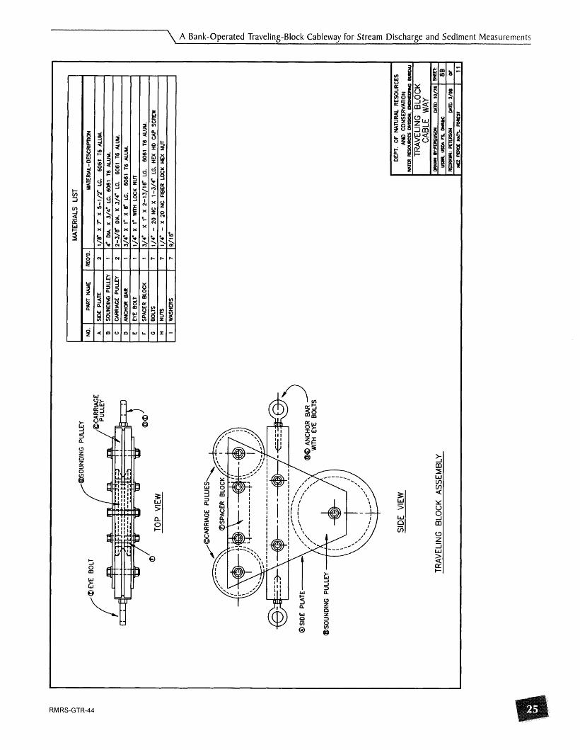
/@SO
UN
DIN
G
PU
LLE
Y
/ a
TOP
VlE
W
I M
ATE
RIA
LS
LIST
B
1 SO
UN
DIN
G P
ULL
EY
I 1
14-
DIA
X
3/4
- LC
. 6
06
1 T
6 A
LUM
.
C
1 CAR
RIA
GE
PU
LLE
Y
1 2
12-3
/#
DIA
, X
3/
4'
LC.
60
61
T6
MU
M.
NO
.
A
D
IWH
~R
eA
R I
1
I3/4
" X I" X
6"
LC
. 6
06
1 T
6 M
UM
. I
PA
RT
NAM
E
SID
E P
LATE
- -
H
) NU
TS
1 7
11/4
" -
X 2
0 N
C
FIB
ER
LO
CK
HEX
NUT
E F C
I I
1 WAS
HER
S 1
7
19
/16
I
REO'
D.
2
J@CA
RRIA
GE
PU
LLIE
S
6SP
AC
ER
B
LOC
K
MA
TER
IAL-
DE
SC
RIP
TIO
N
1/8
' X
7"
X
5-l
/r
LC.
60
61
T6A
LUM
.
7 1 If
- 7n )
rV.
X
1 -3/
4"
LC.
HE
X
HD
CAP
SC
REW
M B
OLT
SP
AC
ER
BLO
CK
RO
lTS
SID
E
VlEW
--
I TR
AV
ELI
NG
B
LOC
K
AS
SE
MB
LY
1 1
DEP
T.
OF
NAT
UR
AL R
ES
OU
RC
ES
AN
D
CO
NS
ER
VA
TIO
N
1/4"
X
1"
W
ITH
LO
CK
NU
T
3/4"
X
1"
X
2-13
/16"
LG
. 6
06
1 T
6 A
LUU
.
WAm
RLU
XRC
lES
DMSK
1W.
PIG
I*EO
R(O
BU
REI
V
TRA
VE
LIN
G
BLO
CK
C
AB
LE
WAY
rn m
mRG
VSO
N
MtE
: io
ns l m

7/16
DR
ILL/
.
@ C
EN
TER
P
LATE
@
BA
CK
ING
P
LATE
MA
TER
IALS
LI
ST
I NO
. I
PART
M
E
( REO
'D. I
MA
TER
IAL-
DES
CR
IPTI
ON
I
@ S
HE
AV
E
SCA
LE: 1/T
=
1"
57
J8
60
64
@
SlD
E
PLA
TE
2 RE
O'O
. W
NE
TO(X
ME
R
CENT
ER
PLAT
E
SID
E PL
ATE
SnEA
M
BA
CK
ING
PLA
TE
U.
S.
DE
PT.
O
F A
GR
ICU
LTU
RE
I FO
RES
T S
EM
RE
CYlW
ON
TRAV
ELIN
G
BLO
CK
1 2 1 1
CA
BLE
WAY
DR
AW
BY:
USSU
ME 8
/79
1 -
314"
X
1-1
/T
X 8"
LG
. 6
06
1-T
65
ll
MU
M.
ALLO
Y R
ECT.
1/Y
X d
X
5-l
/r
LC.
6061
-T65
11
MU
M.
ALLO
Y R
ECT.
60D
10
20 H
R
STL.
R
OU
ND
1/7
X
8 "X
4"
LG
. 60
61 -T
6511
M
UM
. AL
LOY
RECT
.

-
GR
OU
ND
@ H
EA
D
BLO
CK
P
OS
T
7/16
" D
RIL
L/
2 H
OLE
S
@)
TAIL
B
LOC
K
PO
ST
- M
ATE
RIA
LS L
IST
1 I N
O.
I PA
RT
WE
I R
EO'D
. 1 U
ATE
RW
-DE
SC
RIP
TIO
N
I B
LOC
K P
OS
T ; PNVS 6
~ -
70
6"
X 4"
X
3/1
6"
WAL
L R
ECT.
STIK.
STL.
TU
BIN
G
69
HE
AD
MO
UN
T 1
/1 X
4
-1/7
X
17
-3/g
61
020
HR
. ST
L.
FLAT
70
SO
UN
DIN
G M
OU
NT
S X
s"
X 3
/16"
X
1
4-l
/7
LC.
STEE
L AN
GLE
71
TAIL
BL
OC
K PO
ST
6 "X
4-
X
3
/16
W
ALL
REC
T.
STR
L.
SIL
. TU
BIN
G
72
PLAT
E 4
1/T
X 8
" X 16
LC.
1020
HR
. ST
EEL
FIA
T
NO
TES
: I.
PO
STS
uu
n B
E sm T
O W
ITH
STAN
D A
LO
AD O
F 20
00
LEI.
AP
PLI
ED
BY
THE
CABL
E W
AY.
2.
0PTK
)NA
L TW
O PI
ECE
POST
FO
R
REM
OVA
L O
F C
ABLE
WAY
W
ITH
OU
T R
EMO
VAL
OF
UN
DER
GR
OU
ND
SU
PPO
RTS
.
3.
LEN
GTH
OF
POST
MAY
VA
RY
WIT
H
LOC
ATIO
N.
@ O
PTI
ON
AL
TWO
-PIE
CE
P
OS
T TW
O
(2)
PLA
TES
REO
'D.
PER
PO
ST.
LOC
ATE
CLO
SE T
O
GR
OU
ND
LE
VEL.
C
UT
POST
AN
D WELD T
O EA
CH
HALF
AND
BO
LT
Wrm
1/
2"
13
NC
X
1 -
3/4"
LC
. H
EX
HD
BO
LTS.
U.
S.
DE
PT.
O
F A
GR
ICU
LTU
RE
FO
RES
T S
ER
VIC
E
TRAV
ELIN
G
BLO
CK
C
AB
LE W
AY
\ A Bank-Operated Traveling-Block Cableway for Stream Discharge and Sediment Measurements
Installation of posts:
a head block post
tail block post
(4) bags of redimix concrete
Tools & miscellaneous: Post hole digger or shovels. Lumber may be used to brace the posts as the concrete dries. Saws or axes if the site needs to be cleared of brush. Carpenter's level or plumb bob. Waders to cross the stream. Survey level.
Installation of pulley blocks and carriage:
head block, tail block, and carriage
1/8 inch wire rope/cable - aircraft grade cable twice the distance between the posts, with an additional 5-10 feet.
0 (4) 1/8 inch cable clamps
0 (4) 1/8 inch cable thimbles
0 (2) l/4 inch X 16 inch turnbuckles
Tools: wrenches, cable cutter
Cali bration:
(2) colors of enamel paints (paint pens or spray cans)
measuring tape or tagline (100')
sounding reel
El sounding weight

A Bank-Operated Traveling-Block Cableway for Stream Discharge and Sediment Measurements /
Operation:
Other available instruments and models are compatible with our cableway. These may be used depending on the measurements desired and situation. A suggested list:
Item - sounding reel
Model B-56 -
current meter Price AA sounding weight 50C suspended sediment sampler D74 bedload sampler BL84
Estimated cost $ 1,900.00 $ 745.00 $ 275.00 $ 1,370.00 $ 750.00
Hydrological equipment suppliers:
These suppliers are for reference only. Use of trade names is for the convenience of the reader and does not constitute endorsement by the USDA Forest Service. These products are neither tested nor endorsed by the author.
Kckly Hydrological Company 2710 Joyce Avenue Columbus, O H 4321 1 (614)475-8310
Scientific Instruments 5 18 West Cherry Street Milwaukee, WI 532 12 (414) 263-1600
Federal agencies may obtain equipment through:
U .S . Geological Survey Hydrological Instrumentation Facility Building 2 10 1 Stennis Space Center, MS 39529-6000 1-800-382-0634
Federal Interagency Sedimentation Project Waterways Experiment Station 3909 Halls Ferry Road Vicksburg, MS 39180-2721 (601) 634-2721

A Bank-Operated Traveling-Block Cableway for Stream Discharge and Sediment Measurements
SURFACE WATER MONITORING USING THE BANK-OPERATED CABLEWAY Nez Perce National Forest
Ron Torretta, Jim Paradiso
March 1999
Background
Protocols on the Forest have developed based upon standard documented procedures such as Buchanan and Somers (1969). Additional refinements have been made after consulting with the local U.S. Geological Survey, adjacent National Forests, and the USFS Boise Adjudication Team. Being locally refined, the use of the protocols in this paper may not be appropriate in all situations.
Surface water is monitored at eight locations on the Nez Perce National Forest. Some or all of the following data are collected at each of the monitoring sites: discharge, suspended sediment, turbidity, air and water temperature, conductivity, and bedload.
Procedures used when conducting a cableway measurement include most of the same standard steps used for a wading measurement. Initial setup includes checlung the operation of the stage recorder. The beginning time is recorded, as well as stage measurements on the recorder, the staff gage, and inside the stilling well.
Cable measurement periods
Cable measurements are performed whenever the stream or river to be gaged has flows that make gaging via the wading method impossible, impractical, or unsafe. The general rule is to avoid wading in the water any time the product of the velocity (feet per second) and the depth of the water (in feet) is greater than ten.

A Bank-Operated Traveling-Block Cableway for Stream Discharge and Sediment Measurements /
Discharge
Continuous discharge is recorded at the sites with Stevens A-71 or A-35 recorders mounted on stilling wells. Instantaneous discharge is monitored using standard U.S. Geological Survey (USGS) methods as described in "Techniques of Water-Resource Investigations of the USGS", Book 3, Chapters A8 and A6. These data are collected by wading measurement during low flows, using either a Price AA or Pygmy current meter. The Price current meter is suspended from a bridge crane or cableway during high flows.
The current meter is tested before and after use for acceptable operation. For the Price AA meter, minimum spin time of 1 ' 30" is needed in the field. Discharge measurements are recorded on the USGS form #9-275-F, Discharge Measurement Notes, commonly referred to as 'q-notes.' The start and finish times are recorded for discharge, bedload, and suspended sediment measurements. While taking discharge measurements, the time is also recorded every 10 minutes, especially if the water levels appear to be fluctuating. Right Edge Water (REW) or Left Edge Water (LEW), as seen when facing downstream, is recorded on the q-note next to the partial section data. The Distance From Initial Point (DFIP), width, depth, velocity, area, and discharge measurements are recorded and/or calculated the same as for a wading measurement.
The partial sections are measured and then summed for the total discharge, as in a wading measurement. Each partial section should contain no more than 5% of the total flow. The section widths are varied to accomplish this, being narrower in deeper- higher velocity portions of the stream and wider in the shallower-slower portions of the stream. Usually 25-30 total measurements are taken. Measurements are talien beginning at one edge of water and continuing to the other edge.
Set up
During periods of high flows, stations equipped with bank-operated cablewaps most often use a Price AA current meter suspended one foot above a 75 pound Columbus weight. Due to the high velocities, and resulting erratic movement with subsequent damage to equipment, the use of a 30# C weight (0.5 ' suspension) is rarely used at these sites. Set up the cable sounding reel assembly with the Columbus weight and Price AA meter suspended. Check the headphones before moving the equipn~ent into position.
Observation depths
Cable measurements on the Nez Perce National Forest are taken in partial sections with depths that commonly range from zero to about five feet deep. Velocity measurements are typically taken at 6/10 of the distance from the water's surface to the stream bottom, but may be taken at the surface, 2/10, or 8/10 depending on circumstances described below.
In partial sections less than 1.2 feet deep, velocities are estimated, due to limitations o f the meter/weight combination. Use of the price meter is avoided when the cups cannot be completely submerged. On these shallow sections, the velocity is estimated by visually comparing the movement of the water to a deeper nearby section that is measurable, and recording an 'el in the

\ A Bank-Operated Traveling-Block Cableway for Stream Discharge and Sediment Measurements
observation depth column of the q-note. If that is not possible, a surface velocity is taken with the Price meter (recording an 's' in the observation depth column of the q-note). Measurements taken at the surface are corrected using a 0.87 correction factor.
In partial sections between 1.2 ' and 1.9' deep, the measurement is considered a 0.2 depth observation. When a 0.2 depth observation is the only measurement in a vertical, a 0.87 correction factor is used to convert the measured velocity to the average for the column. For example, a velocity of 6.84 feet per second (fps) measured at the point is corrected to a velocity of 5.95 fps as the mean in vertical.
In partial sections between 2.0 ' to 2.3 ' deep, the measurement is recorded as a 0.5 depth observation. No correction is made, but the notation acknowledges that the measurement is not a true 0 .6 depth measurement.
In partial sections between 2.4' to 5.0 ' deep, a 0.6 depth observation is taken. No correction is necessary t o convert the reading to the mean in the vertical.
On depths over 5.0 feet, the velocity is measured at both the 0.2 and 0.8 observation points. These two readings are averaged for the mean in vertical.
The hydrographer may find it convenient to summarize the above information on a table to facilitate field use.
Setting the observation depth
The depth of the Price meter is set using the dial indicator on the sounding reel.
Zero the meter with the bottom of the weight just touching the water's surface. This has been found easier in high velocity water, than zeroing with the meter at the waters surface.
Lower the equipment to the stream bottom, reading and recording the depth from the dial.
Raise the equipment t o the appropriate depth for the measurement, using the dial on the meter.
Additional corrections to velocity
Suspension angle coefficients to correct for downstream drift are assumed to be 1.0. Cable length is not enough to significantly affect actual stream depth vs. measured depth. Horizontal angle corrections of the water are difficult t o determine from a vantage point on a stream bank. This correction is made for water that is not flowing perpendicular t o the cross section. The horizontal angle coefficient is assumed to be 1.0 unless the observer can detect a more accurate angle from the observation position.

A Bank-Operated Traveling-Block Cableway for Stream Discharge and Sediment Measurements /
Suspended sediment
Suspended sediment (SS) samples are collected using the Equal Width Increment (EWI) method. Procedures are similar to those used when conducting SS measurements while wading, and described in Edwards and Glysson ( 198 8).
All partial sections for sampling have the same width.
Collect 10 EWI suspended sediment samples for all partial sections with a downstream flow.
Select an appropriate sized nozzle and establish a transit rate for lowering and raising the sampler to collect 2 4 bottles of SS for analysis. The transit rate must be consistent for all sections and must not allow a bottle to overfill in any one section.
Use the sounding reel to lower and raise the D79 suspended sediment sampler. Transit rates for depth-integrated suspended-sediment measurements can be calculated using revolutions of the sounding reel. The A-55 reel has a drum circumference of 1 foot and the B - 5 6 reel a circumference of 1.5 feet. Thus, when using a B - 5 6 reel, the handle is turned once each second for a 1.5 fps transit rate.
&r/water temperatures and conductivity measurements are made after the suspended sediment samples are taken, since there is a relationship between water temperature and amount of SS that the water holds. The automatic (ISCO) sampler, if present, should be serviced/changed next and an ISCO calibration sample collected to correlate with the SS samples collected across the stream channel.
Bedload
The bedload sample is also collected using the EWI method. The sounding reel is used to raise and lower the bedload sampler.
Approximately twenty subsamples are collected. The subsamples are stored for lab analysis as one sample.
The bedload sampler is positioned on the stream bottom for 60 seconds at each location.
Record any special circumstances in the notes. Subsamples are taken only in verticals with positive velocities. In places where the sampler cannot be placed on the streambed due to boulders or other obstructions, the subsample may have to be foregone.

\ A Bank-Operated Traveling-Block Cableway for Stream Discharge and Sediment Measurements
Close station
One last record of all stage indicators (outside gage, pulley, inside gage or tapedown, and pen) should be recorded, both on the chart and the Q-notes sheet, before leaving the site. The strip chart should be reset to correct time and gage height before leaving, if necessary. Record any adjustments made on the log and Q-note sheets.
Remove the sounding reel and lock the cable to deter vandalism.
References
Buchanan, Thomas J. and William Somers. 1969. Discharge Measurements At Gaging Stations. Techniques of Water-Resources Investigations. U.S. Geological Survey. Boolc 3, Chap. A8.
Carter, R.W. and Jacob Davidian. 1968. General Procedures for Gaging Streams. Tech- niques of Water-Resources Investigations. Book 3, Chap. A6.
Edwards, Thomas I<. and Glysson, G. Douglas. 1988. Field Methods For Measurement Of Fluvial Sediment. Techniques of Water-Resources Investigations. U.S. Geological Survey. Book 3, Chap. C2.
USGS Hydrologic Instrumentation Facility. Q-Card for measuring water discharge. Reference Water-Supply Paper 2 175.


ROCKY MOUNTAIN Research Station
The Rocky Mountain Research Station develops scientific information and technology to improve management, prdtection, and use of forests and rangelands. Research is designed to meet the needs of National Forest managers, federal and state agencies, public and private organizations, academic institutions, industry, and individuals..
Studies accelerate solutions to problems involving ecosystems, range, forests, water, recreation, fire, resource inventory, land reclamation, community sustainability, forest engineering technology, multiple use economics, wildlife and fish habitat, and forest insects and diseases. Studies are conducted cooperatively, and applications can be found worldwide.
Research Locations
Flagstaff, Arizona Fort Collins, Colorado* Boise, ldaho Moscow, ldaho Bozeman, Montana Missoula, Montana Lincoln, Nebraska
Reno, Nevada Albuquerque, New Mexico Rapid City, South Dakota Logan, Utah Qgden, Utah Provo, Utah Laramie, Wyoming
* Station Headquarters, 2150 Centre Avenue, Building A, Fort Collins, CO 80526
The U.S. Department of Agriculture (USDA) prohibits discrimination in all its programs and activities on the basis of race, color, national origin, sex, religion, age, disability, political beliefs, sexual orientation, or marital or family status. (Not all prohibited bases apply to all programs.) Persons with disabilities who require alternative means for communication of program information (Braille, large print, audiotape, etc.) should contact USDA's TARGET Center at (202) 720-2600 (voice and TDD).
To file a complaint of discrimination, write USDA, Director, Office of Civil Rights, Room 326-W, Whitten Building, 1400 Independence Avenue, SW, Washington, D.C. 20250-9410 or call (202) 720-5964 (voice and TDD). USDA is an equal employment opportunity provider and employer.
Printed on recycled paper