A-37 Manual
18
rA-37 1 r A-37 MIDI Controller Owner’s Manual Thank you, and congratulations on your choice of the Roland A-37 MIDI Controller. The A-37 is a powerful, easy-to-oper- ate, dedicated keyboard controller for MIDI sound modules (whether or not they are GM2/GM/GS compatible). Please take the time to read through this Owner’s Manual. That way, you can feel assured that you understand every feature the A-37 offers, and will enjoy many years of trouble-free operation. The Roland A-37 is a MIDI keyboard controller. It does not c ontain any sound-generating circuitry. It is designed to trans- mit note messages, program changes, bank select messages as well as a variety of other MIDI messages (such as Reverb and Chorus Send levels) to an external sound module. To avoid confusion, let’s agree to… • …use the word “button” for all keys on the f ront panel, and only use “key” when referring to the A-37’s keyboard. • …say “sequencer” when r eferring to both har dware sequencers (like the Roland MC-80) and computers with sequencer software. • …talk about “MIDI instruments” to signify both isolated (“monotimbral”) instruments and parts/timbres/voices/multi channels of a multitimbral module or synth. The contents of the illustrations appearing in this manual may differ slightly from what you see when you start using your instrument. Before using this instrument, carefully read the sections entitled “Using the unit safely” and “Important notes”. These sec- tions provide important information concerning the proper operation of the A-37. Be sure to keep this manual in a safe place for future reference. Copyright ©2001 ROLAND EUROPE. All rights reserved. No part of this publication may be reproduced in any form without the written permission of Roland Europe s.p.a.
Transcript of A-37 Manual

8/3/2019 A-37 Manual
http://slidepdf.com/reader/full/a-37-manual 1/18
r A-37
1
r
A-37MIDI Controller
Owner’s Manual
Thank you, and congratulations on your choice of the Roland A-37 MIDI Controller. The A-37 is a powerful, easy-to-oper-ate, dedicated keyboard controller for MIDI sound modules (whether or not they are GM2/GM/GS compatible). Please takethe time to read through this Owner’s Manual. That way, you can feel assured that you understand every feature the A-37offers, and will enjoy many years of trouble-free operation.
The Roland A-37 is a MIDI keyboard controller. It does not contain any sound-generating circuitry. It is designed to trans-mit note messages, program changes, bank select messages as well as a variety of other MIDI messages (such as Reverband Chorus Send levels) to an external sound module.
To avoid confusion, let’s agree to…• …use the word “button” for all keys on the front panel, and only use “key” when referring to the A-37’s keyboard.• …say “sequencer” when referring to both hardware sequencers (like the Roland MC-80) and computers with
sequencer software.• …talk about “MIDI instruments” to signify both isolated (“monotimbral”) instruments and parts/timbres/voices/multi
channels of a multitimbral module or synth.
The contents of the illustrations appearing in this manual may differ slightly from what you see when you start using yourinstrument.
Before using this instrument, carefully read the sections entitled “Using the unit safely” and “Important notes”. These sec-tions provide important information concerning the proper operation of the A-37. Be sure to keep this manual in a safeplace for future reference.
Copyright ©2001 ROLAND EUROPE. All rights reserved.No part of this publication may be reproduced in any form without the written permission of Roland Europe s.p.a.

8/3/2019 A-37 Manual
http://slidepdf.com/reader/full/a-37-manual 2/18
Owner’s Manual
2
Usingtheunit safely
• Before using this instrument, make sure to read theinstructions below, and the Owner’s Manual.
• Do not open (or modify in any way) the instrument,and avoid damaging an optional adapter.
• Do not attempt to repair the instrument, or replaceparts within it. Refer all servicing to your retailer, thenearest Roland Service Center, or an authorizedRoland distributor, as listed on the “Information”page.
• Never use or store the A-37 in places that are:• Subject to temperature extremes (e.g., direct sun-
light in an enclosed vehicle, near a heating duct,on top of heat-generating equipment); or are
• Damp (e.g., baths, washrooms, on wet oors); orare
• Humid; or are• Exposed to rain; or are• Dusty; or are• Subject to high levels of vibration.
• When using an optional adaptor, make sure the linevoltage at the installation location matches theinput voltage specied on the name plate.
• Do not allow any objects (e.g., ammable material,coins, pins); or liquids of any kind (water, soft drinks,etc.) to penetrate the instrument.
• Immediately turn the power off, remove the adaptorfrom the outlet, and request servicing by yourretailer, the nearest Roland Service Center, or anauthorized Roland distributor, as listed on the “Infor-mation” page when:• Objects have fallen into, or liquid has been spilled
onto the instrument; or• The instrument has been exposed to rain (or oth-
erwise has become wet); or• The instrument does not appear to operate nor-
mally or exhibits a marked change in perfor-mance.
• In households with small children, an adult shouldprovide supervision until the child is capable of fol-lowing all the rules essential for the safe operationof the unit.
• Protect the instrument from strong impact.Do not drop it!
• When using an optional adaptor, do not force it toshare an outlet with an unreasonable number of other devices. Be especially careful when usingextension cords—the total power used by all devices
you have connected to the extension cord’s outletmust never exceed the power rating (watts/amperes)for the extension cord. Excessive loads can cause theinsulation on the cord to heat up and eventuallymelt through.
• Before using the instrument in a foreign country,consult with your retailer, the nearest Roland ServiceCenter, or an authorized Roland distributor, as listedon the “Information” page.
• The instrument and the optional adaptor should be
located so their position does not interfere with theirproper ventilation.
• Whenever the instrument is to remain unused for anextended period of time, disconnect the optionaladaptor if you have one.
• Try to prevent cords and cables from becomingentangled. Also, all cords and cables should be placedso they are out of the reach of children.
• Never climb on top of, nor place heavy objects onthe instrument.
• Never handle the batteries or optional adaptor withwet hands when plugging into, or unplugging from,an outlet or the A-37.
• Before cleaning the A-37, turn off the power andunplug the optional adaptor from the outlet.
Used for instructions intended to alertthe user to the risk of injury or materialdamage should the unit be usedimproperly.
* Material damage refers to damage orother adverse effects caused withrespect to the home and all itsfurnishings, as well to domesticanimals or pets.
Used for instructions intended to alert
the user to the risk of death or severeinjury should the unit be usedimproperly.
The q symbol alerts the user to things that must becarried out. The specific thing that must be done isindicated by the design contained within the circle. Inthe case of the symbol at left, it means that the power-cord plug must be unplugged from the outlet.
The symbol alerts the user to important instructions
or warnings.The specific meaning of the symbol isdetermined by the design contained within thetriangle. In the case of the symbol at left, it is used forgeneral cautions, warnings, or alerts to danger.
The symbol alerts the user to items that must never be carried out (are forbidden). The specific thing thatmust not be done is indicated by the design containedwithin the circle. In the case of the symbol at left, itmeans that the unit must never be disassembled.
8/3/2019 A-37 Manual
http://slidepdf.com/reader/full/a-37-manual 3/18
r A-37
3
In addition to the items listed under “USING THE UNIT SAFELY” (page 2), please read and observe the following:
Power supply• The A-37 can be operated using batteries or an optional adap-
tor. Be careful to insert the batteries the right way around. If you prefer to use an adaptor, be sure to purchase a RolandACA model.
• Before connecting the A-37 to other devices, turn off thepower to all units. This will help prevent malfunctions and/ordamage to other devices.
Placement• Using the A-37 near power ampliers (or other equipment
containing large power transformers) may induce hum. Toalleviate the problem, change the orientation of this instru-ment; or move it farther away from the source of interfer-ence.
• This instrument may interfere with radio and television recep-tion. Do not use it in the vicinity of such receivers.
• Do not expose the A-37 to direct sunlight, place it neardevices that radiate heat, leave it inside an enclosed vehicle,or otherwise subject it to temperature extremes. Excessiveheat can deform or discolor the instrument.
Maintenance• For everyday cleaning wipe the A-37 with a soft, dry cloth or
one that has been slightly dampened with water. To removestubborn dirt, use a mild, non-abrasive detergent. Afterwards,be sure to wipe the instrument thoroughly with a soft, drycloth.
• Never use benzene, thinners, alcohol or solvents of any kind,to avoid the possibility of discoloration and/or deformation.
Repairs and data• Please be aware that all data contained in the instrument’s
memory may be lost when it is sent for repairs. Importantdata should always be backed up via MIDI (see p. 12). In cer-tain cases (such as when circuitry related to memory itself isout of order), we regret that it may not be possible to restorethe data. Roland assumes no liability concerning such loss of data.
Additional precautions• Please be aware that the memory contents can be irretriev-
ably lost as a result of a malfunction, or the improper opera-tion of the instrument. To protect yourself against the risk of losing important data, we recommend that you periodicallysave a backup copy of important data in the instrument’smemory.
• Use a reasonable amount of care when using the instrument’s
buttons, other controls, and jacks/connectors. Rough handlingcan lead to malfunctions.
• Never strike or apply strong pressure to the display.
• When connecting/disconnecting MIDI cables, grasp the con-nector itself—never pull on the cable. This way you will avoidcausing shorts, or damage to the cable’s internal elements.
• A small amount of heat will radiate from the instrument dur-ing normal operation. This is perfectly normal.
• When you need to transport the instrument, package it in thebox (including padding) that it came in. Otherwise, you willneed to use equivalent packaging materials, or a ightcase.
Important notes. . . . . . . . . . . . . . . . . . . . . . . . . . . . . 3
1. The A-37 in a nutshell . . . . . . . . . . . . . . . . . . . . . 4
2. Panel descriptions . . . . . . . . . . . . . . . . . . . . . . . . . 5
3. The basics . . . . . . . . . . . . . . . . . . . . . . . . . . . . . . . . 63.1 Inserting or replacing the batteries . . . . . . . . . . . . . . .6
3.2 Connecting an optional AC adaptor. . . . . . . . . . . . . . .63.3 Connecting the A-37 . . . . . . . . . . . . . . . . . . . . . . . . . . . 63.4 Powering up . . . . . . . . . . . . . . . . . . . . . . . . . . . . . . . . . . .7
4. Keyboard modes . . . . . . . . . . . . . . . . . . . . . . . . . . 8
5. Configuring the A-37 . . . . . . . . . . . . . . . . . . . . . . 95.1 Selecting the parameter to be edited. . . . . . . . . . . . . .95.2 CONTROL parameters . . . . . . . . . . . . . . . . . . . . . . . . . .105.3 DATA parameters . . . . . . . . . . . . . . . . . . . . . . . . . . . . . . 115.4 PRG CHG parameters . . . . . . . . . . . . . . . . . . . . . . . . . .14
6. Miscellaneous. . . . . . . . . . . . . . . . . . . . . . . . . . . . 166.1 Transpose . . . . . . . . . . . . . . . . . . . . . . . . . . . . . . . . . . . .166.2 About MIDI Thru . . . . . . . . . . . . . . . . . . . . . . . . . . . . . . 166.3 Working with Patches. . . . . . . . . . . . . . . . . . . . . . . . . .166.4 Restoring the factory settings. . . . . . . . . . . . . . . . . . .176.5 Specifications . . . . . . . . . . . . . . . . . . . . . . . . . . . . . . . . .17
Important notes
Contents
8/3/2019 A-37 Manual
http://slidepdf.com/reader/full/a-37-manual 4/18
Owner’s Manual
4
Four keyboard modesThe A-37’s semi-weighted 76-note keyboard can beused in Layer, Split, and Whole modes.
Perfect controlThe A-37 puts you in control of all things MIDI inyour keyboard rig. Velocity sensitivity, Aftertouch,Modulation, and Pitch Bend are built in – and can beset for the Upper and Lower sections independently.Then there is also a DATA ENTRY slider that can beassigned to any control change number betweenCC00 and CC119. Finally, the A-37 sports connectorsfor an optional Sustain foot switch and an expres-sion pedal.Of course, you can also transpose the Upper andLower sections – either in octave or semitone steps.
This would allow you, for instance, to play a mean-ingful bass line with your right hand and a solo partwith your left.
128 Patch memoriesThe A-37 comes with 128 Patch memories whereyou can save almost all settings, plus the MIDI chan-nels for the Upper and Lower sections, and BankSelect/Program Change numbers to be transmittedon both section channels (where applicable) when-ever you select the Patch in question.Once you have used up all 128 internal Patch mem-ories and need even more setups, you can archiveyour existing settings via MIDI (Bulk Dump func-tion).
Two independent MIDI loops and sequencer controlThe A-37 comes with two MIDI OUT sockets (A andB). By assigning an “A” channel (1A~16A) to theUpper and/ or Lower section, you tell the A-37 totransmit the related note and other MIDI messagesto its MIDI OUT A socket. Select a “B” channel(1b~16b) if you wish to control a separate MIDI rigvia MIDI OUT B.You can also set the tempo for an externalsequencer and store that value in a Patch – alongwith the setting that species whether such mes-sages should be transmitted to the MIDI OUT A or Bsocket – or both.
Supports Roland’s GS FormatThe GS Format is a standardized set of specicationsfor Roland’s sound sources which denes the man-ner in which multitimbral sound modules willrespond to MIDI messages. All devices compatiblewith the GS Format bear the GS logo. Every moduleor instrument bearing the GS logo will respond in
the same way to the MIDI messages sent from theA-37.All Roland GS sound modules also fully supportLevel 1 of the General MIDI System. The A-37 is alsoGM2-compatible.
Important noteWhen using an AC adaptor, use only the specieddevice (Roland ACA series). Use of any other ACadaptor could result in damage, malfunction orelectric shock.
1. The A-37 in a nutshell

8/3/2019 A-37 Manual
http://slidepdf.com/reader/full/a-37-manual 5/18
r A-37
5
A BENDER/MODULATION leverUse this lever to transmit Pitch Bend (left/rightmovements) or Modulation messages (CC01, move-ments towards the back of the A-37).
B DATA ENTRY sliderThis slider can be used to transmit the assigned MIDI
messages in realtime.C KEYBOARD MODE buttons
Press one of these buttons to select a Whole mode,or the Layer or Split mode. See page 8.
D EDIT buttonsPress one of these buttons ([CONTROL], [DATA], or[PRG≈CHG]) to select the corresponding EDIT level.You can then use the numeric keypad to call up theparameter you wish to set.
E DisplayThis three-character display keeps you posted about
the selected Patch memory, the tempo, or theparameter value you set.
F A/B button, numeric keypad (PATCH/PARAMETER)If none of the EDIT buttons lights, the buttons[A/B] and [1]~[8] allow you to enter the number of thedesired Patch memory (two banks of 64 memorieseach). After pressing one of the EDIT buttons, thebuttons [A/B], [1]~[8]and [TRANSPOSE](which thenfunctions as[9]) can be used for selecting thedesired parameter (see p. 9).
G ENTER buttonPress this button to conrm a setting or a selection.
H EXIT buttonPress this button to leave the currently selected EDITlevel, or to ignore the value you just set (thusreturning to the previously set value).
I TRANSPOSE buttonUsually, this button allows you to switch the A-37’skeyboard transposition on and off and for settingthe transposition interval. When[CONTROL],[DATA],or [PRG≈CHG]lights, however, this buttonscan be used for selecting a parameter (in which caseit functions as[9]).
J DOWN/UP buttonsThese buttons can be used for entering Patch mem-ories, EDIT parameters, or parameter values. In cer-tain cases, pressing them simultaneously will switchthe selected parameter on and off. Pressing themsimultaneously recalls the default value of theselected parameter.
K WRITE buttonPress this button to save the current settings to oneof the A-37’s Patch memories. Writing a Patch alsoinvolves pressing other buttons (see p. 16).
L SEQUENCER[START/STOP]buttonThis button allows you to transmit MIDI Start andStop messages to start or halt playback of an exter-nal sequencer.
M FOOT PEDAL socketThis is where you can connect an optional RolandEV-5 or FV-300L expression pedal.
N HOLD SWITCH socketThis is where you can connect an optional DP-2,DP-6, or BOSS FS-5U footswitch to sustain thenotes you are playing (Hold, CC64).
O MIDI THRU, OUT B, OUT A, IN socketsConnect these sockets to the MIDI sockets of thedevices you wish to control, or the devices thatshould transmit MIDI messages to the A-37.
P DC IN socketThis is where you can connect an optional ACAadaptor.
Q POWER switchSet this switch to the ON position to switch theA-37 on. Select the OFF position to power off yourA-37.
2. Panel descriptions

8/3/2019 A-37 Manual
http://slidepdf.com/reader/full/a-37-manual 6/18
Owner’s Manual
6
3.1 Inserting or replacing thebatteriesThe A-37 can be powered either by batteries or an
AC adaptor.
Battery replacementSix AA batteries are required to run the A-37 on bat-tery power. We recommend the use of alkaline bat-teries because they will provide a more stable, long-lasting source of power. With alkaline batteries, youcan expect about 25 hours of continuous operation,although this depends on how the A-37 is beingused.Note: Avoid using new batteries together with oldones. In addition, avoid mixing different types of bat-teries (e.g. regular carbon and alkaline batteries).Note: When replacing batteries, be sure to insert themcorrectly (ensure correct polarity).Note: Remove the batteries whenever the A-37 is toremain unused for an extended period of time.
(1) Switch off the A-37.(2) Remove the battery cover located on the bottom of
the instrument.
(3) Take out the battery case, then insert the six batter-ies supplied with the A-37 (three on either side).
(4) Insert the battery case and close the battery cover.
3.2 Connecting an optional ACadaptorBe sure to use only the specied AC adaptor (Roland
ACA series). Using any other type may cause mal-function or electric shock.Note: If the A-37 is to remain unused for an extendedperiod of time, unplug the adaptor.
(1) Switch off the A-37.(2) First connect the AC adaptor to the A-37’s DC IN
socket, then connect the large plug to a power out-let.
3.3 Connecting the A-37Note: Switch off both the A-37 and the externalinstrument(s) before establishing or breaking the MIDIconnections.The A-37 is a MIDI controller. It contains no sound-generating circuits of its own. You need to connectit to at least one external MIDI instrument in orderto hear what you are playing. Here are the basicconnections:
Note: Do not forget to connect the module, synthe-sizer, etc., to an amplier. See its manual for details.
3. The basics
(a) Press the tabs for-ward.
(b) Lift up.
MIDI OUT A or B
MIDI IN
A-37 (transmits MIDI messages)
Module, synthesizer, etc. (receives MIDI messages)
8/3/2019 A-37 Manual
http://slidepdf.com/reader/full/a-37-manual 7/18
r A-37
7
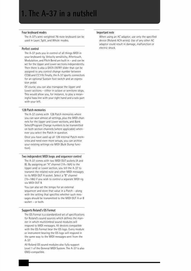
Working with a computer or sequencerIf you want to use the A-37 as Master keyboard forrecording applications that involve a computer withsequencing software or a hardware sequencer (likethe Roland MC-80), here is the most useful connec-tion system:
This setup only works as expected if the followingconditions are met:
• The computer (if that is what you use) must beequipped with a MIDI interface.
• You need to switch on the sequencer’s MIDI SoftThru/MIDI Echo function. Otherwise you won’t hear
what you are playing. (See the sequencer’s/soft-ware’s manual for details.)Note: The MIDI channel you set on the A-37 (see p. 11)may be changed to another number by the sequencer.If that is not the case, be sure to set at least one of theA-37’s zones to the MIDI channel the module (not thesequencer) is receiving on.Note: Yet other congurations are possible, but theabove usually cover most of your MIDI needs. Youcould connect the MIDI IN socket of a second moduleto the a MIDI THRU socket of the module picturedabove for an even larger system.Or you could establish the following connection:
[Sequencer] MIDI OUT→
[A-37] MIDI IN[A-37] MIDI THRU→ [Module] MIDI IN(Alternative: [A-37] MIDI OUT A→ [Module] MIDI IN,see also “About MIDI Thru” (p. 16)).Note: It is also possible to use the A-37 MIDI OUT Aand MIDI OUT B sockets simultaneously for controllingtwo separate MIDI chains.
3.4 Powering upPower to the various devices should be turned on inthe appropriate order. First, turn on the units thattransmit MIDI messages (computer, A-37). Next,turn on the sound module(s)/synthesizers, then theamplication system.
Set the A-37’s power switch (rear panel) to the ONposition.Power off your system in the reverse order.Note: The A-37 is equipped with a circuitry protectionfeature. At power-up, a brief interval is required beforeit will operate normally.Note: If the A-37 is powered using batteries, be sure toswitch it off whenever you are not planning to use itfor a while (5 minutes or more). But before doing so,you may wish to save the current settings to a Patchmemory (see p. 16).
MIDI OUT A or B
MIDI IN
A-37 (transmits MIDImessages)
Computer or sequencer(records and transmitsMIDI messages)
Module, synthesizer, etc. (receives MIDI messages)
MIDI OUT
MIDI IN

8/3/2019 A-37 Manual
http://slidepdf.com/reader/full/a-37-manual 8/18
Owner’s Manual
8
Your A-37 has three buttons that allow you to selectone of four Keyboard modes. The KEYBOARD MODEdetermines how many zones and/or MIDI channelscan be used simultaneously.
Whole Upper
This mode means that the Upper section is assigned
to the entire keyboard. All messages generated onthe A-37 are therefore transmitted on the Upperchannel. Press the[UPPER]button to select thismode.
Whole Lower
This mode means that the Lower section is assignedto the entire keyboard. All messages generated onthe A-37 are therefore transmitted on the Lowerchannel. Press the[LOWER]button to select thismode.Alternately pressing[UPPER]and [LOWER]allowsyou to control different MIDI instruments as andwhen needed. Example: you could use the Lowersection for controlling an organ sound of one mod-
ule (or part), and the Upper section for playing alead synthesizer part using a different MIDI instru-ment.
Split
In Split mode, the Lower section is assigned to theleft half of the keyboard, while the Upper section isassigned to the right. This allows you to control twodifferent MIDI instruments via separate channels(Lower and Upper). Press the[SPLIT]button to selectthis mode.
At rst, the Split point is located at the “C” keyslightly left off center. This key is called theC4 .Here’s how to select another split point between the“F1” and the “Gb7” (see the following illustration):
(1) Press and hold the[SPLIT]button.(2) While still holding that button, press the key that
should become the lowest note of the Upper sec-tion.You can also use the[DOWN]/[UP]buttons.
(3) Release both the[SPLIT]button and the key youpressed.Note: This setting can be saved to a Patch. Your KEY-BOARD MODE selection is also saved.Note: To return to the default setting (C4), simultane-souly press[DOWN]/[UP].
Layer (Lower + Upper)
In Layer mode, the A-37 transmits on two MIDIchannels simultaneously (assigned to Lower andUpper). Every action on the A-37 is thus translated
into two MIDI message strings. Hold down[LOWER] while pressing[UPPER]to select this mode.To leave it, press[LOWER], [UPPER], or [SPLIT].
4. Keyboard modes
Upper section assigned to all keys
Lower section assigned to all keys
Lower section Upper section
Possible range for the Split point
Lower section + Upper section (two dif ferent MIDI channels)

8/3/2019 A-37 Manual
http://slidepdf.com/reader/full/a-37-manual 9/18
r A-37
9
Your A-37 comes with a great many MIDI parameters, or message types that can be transmitted so as to control your MIDIrig to your liking. Most of the following parameters can be set for the Upper and Lower sections independently – and mostof them can be saved to a Patch memory (see p. 16).
Note: The available EDIT parameters will be presentedin the order they can be selected. See page 11 if all youwant to do for the time is being is assign different MIDIchannels to the Upper and/or Lower sections.
5.1 Selecting the parameter to beeditedThe A-37’s Edit parameters can be accessed via threebuttons:
When none of the above buttons lights, you are in“play mode” (i.e. where you cannot change theabove parameters). That also means that thenumeric keypad ([A/B], [1]~[8]) can be used forselecting Patch memories.After pressing[CONTROL], [DATA], or [PRG≈CHG],however, the buttons[0] (A/B)[1]~[8] and [9] (TRANSPOSE) allow you to select the desired param-eter. These numbers appear below the buttons andare printed in orange (just like the EDIT button leg-ends). See the illustration at the top of this page.
Here is how to select the desired parameter:
(1) Look at the legends above the[0]~[9]buttons to ndout which EDIT button you need to press.
(2) Press[CONTROL], [DATA], or [PRG≈CHG], dependingon the row that contains the desired parameter.The number of the rst parameter now ashes inthe display.
(3) Use the[0]~[9] buttons or [DOWN]/[UP]to select aparameter.
After about three seconds, the display shows thevalue currently set for the selected parameter.
(4) Press[LOWER]or [UPPER]to select the keyboardsection whose settings you wish to change.Note: It is now no longer possible to select a differentKEYBOARD MODE. You need to leave the EDIT modealtogether before being able to do that.
(5) Use[0]
~[9]
or[DOWN]
/[UP]
to make the desired set-ting.Some parameters can be set to0FF . To do so, simul-taneously press[UP]and [DOWN].
(6) Press[ENTER]to conrm the value or setting.
Press[EXIT]to return to the previous value.(7) Press[EXIT]if you want to select another parameter
from the active EDIT group.
5. Conguring the A-37
Button Function
[CONTROL](page 10)
Provides access to all parameters related tothe available (or optional) performancefunctions, like Pitch Bend, modulation,Aftertouch, etc.
[DATA] (page 11)
Provides access to more specic and staticMIDI parameters: transmit channel, volume,etc., but also the Dump function.
[PRG≈CHG](page 14)
Allows you to set and transmit memoryselection clusters (Bank Select, ProgramChange), to set the MIDI tempo, and tospecify to which MIDI OUT socket to use forthese messages.

8/3/2019 A-37 Manual
http://slidepdf.com/reader/full/a-37-manual 10/18
Owner’s Manual
10
To select a parameter from a different group, pressthe corresponding EDIT button ([CONTROL], [DATA],[PRG≈CHG]), then return to step (3) above.
(8) Press[EXIT]yet again to leave the EDIT mode.
You will achieve the same result by pressing thelighting EDIT button (it then goes dark).Note: See page 16 if you wish to save the settings youhave just made as a Patch.
5.2 CONTROL parametersAs stated earlier, this is where you will nd all parameters that are related to the A-37’s on-board or optional perfor-mance functions. This level also contains a parameter that allows you to check the state of the batteries.
[0] den (Data Entry) Upper, LowerThis parameter allows you to assign a controlchange number (CC) to the A-37’s[DATA≈ENTRY] slider. The slider can then be used for realtime con-trol of the related function. You can assign anynumber between CC00 and CC119. Given their dedi-cated use for memory bank selection (see p. 14),CC00 and CC32 are unlikely candidates for otherassignments. Assigning them to the[DATA≈ENTRY] slider therefore makes little sense.If you assign CC10 (Pan) to this slider, positionsbelow the center correspond to the left side, whilesettings above the center correspond to the right.Note: Certain MIDI instruments may not respond inrealtime to CC10 changes, because they only imple-ment Pan changes at the beginning of a new note(Note-on message).
It is also possible to select0FF (by simultaneouslypressing[DOWN]/[UP]), which means that the[DATA≈ENTRY]slider performs no function at all.Note: See the manual of the MIDI instrument to becontrolled for the CC numbers it supports for realtimecontrol.
Note: The CC assignment can be different for theUpper and Lower sections. This allows you, for example,to control the Pan setting (CC10) via the Upper section,and the Delay Send Level (CC94) via the Lower section.
[1] hld (Hold) Upper, LowerThis parameter allows you to specify (for Upper andLower separately) whether the selected sectionshould (0N ) or should not (0ff ) transmit Hold(CC64) messages. This is only relevant if you connectan optional DP-2, DP-6, or BOSS FS-5U to theA-37’s HOLD SWITCH socket.
[2] bnd (Pitch Bend) Upper, LowerThis parameter allows you to specify whether theselected section should (0N ) or should not (0ff )transmit Pitch Bend messages when you use theA-37’s BENDER/MODULATION lever.
[3] mod (Modulation) Upper, LowerThis parameter allows you to specify whether theselected section should (0N ) or should not (0ff )transmit Modulation messages (CC01) when you usethe A-37’s BENDER/MODULATION lever.
CC01 messages can be used for creating vibrato,tremolo, or WahWah effects. This depends on howthe receiving MIDI instrument uses these messages.
[4] Uel (Velocity) Upper, LowerThis parameter allows you to assign a velocity curveto the selected section. The A-37’s keyboard isvelocity sensitive and very responsive to nuances of your playing. You may, however, be controlling aMIDI instrument that does not interpret the velocityvalues in the desired way. Rather than reprogramthe sound (if that is at all possible), you can simplyselect another curve on the A-37 so that your strik-ing force is translated in a different way and thusmore usable for the part you wish to play.SelectL (light) if the section in question shouldsend high velocity values even when you strike thekeys with light-to-medium force.M(medium) is thedefault setting, which produces a natural response.H (heavy), is the way to go if the external MIDIinstrument is too loud/bright when you play nor-mally.SelectLL if all note messages of the section inquestion are to be transmitted with more or less thesame velocity value. Extreme differences in dynam-
ics (hitting very hard and very soft) will, however,allow you to trigger velocity switches if the receiv-ing MIDI instrument supports that feature. This set-ting is thus not the same as “off” on other instru-ments – but it is very similar.

8/3/2019 A-37 Manual
http://slidepdf.com/reader/full/a-37-manual 11/18
r A-37
11
[5] oct (Octave) Upper, LowerThis parameter is especially useful in Split mode (seep. 8), when you wish to use your left hand for achord backing whose register is close to the part youplay with your right hand. Of course, you can alsotranspose (or “shift”) the Upper part in octave steps,which may be useful in Layer mode.The setting range is –2, –1, 0, 1, 2 octaves (down orup). Note that the A-37’s keyboard can also betransposed in semitone steps. See page 16.
[6] aft (Aftertouch) Upper, LowerThe A-37’s keyboard transmits channel Aftertouchmessages – if you want it to. Select0n if the activesection should indeed do so. Select0FF to keep asection from transmitting Aftertouch messages.Especially when working with a sequencer, it is usu-ally wiser to select0n only if you really want After-touch messages to be recorded. Aftertouch indeedgenerates a continuous stream of values that takeup a lot of memory. If the receiving MIDI instrumentdoes not respond to them, it would be a good ideanot to transmit them in the rst place.Note: “Channel Aftertouch” refers to the fact that onlyone Aftertouch value (the highest) is transmitted atany one time, even though you may be playing chords.
[7] ftp (Foot Pedal/Expression) Upper, LowerThis parameter allows you to specify whether theselected section should (0n ) or should not (0ff )transmit expression (CC11) messages.The third possibility,inU , is very interesting indeedfor the Layer mode (see p. 8): by assigning0n to theUpper section, andinU to the Lower section, forexample, you can increase the volume of the UpperMIDI channel and simultaneously decrease that of the Lower MIDI channel by pressing the pedal down(toe down) – and vice versa. This allows for somenifty “sound morphing”.This parameter is only relevant if you connect anoptional EV-5 or BOSS FV-300L expression pedal tothe A-37’s FOOT PEDAL socket.
[8] bch (Battery Check)This parameter allows you to check the voltage of the batteries (0~100). The value “0” means that thebatteries should be dead by now, while “100” repre-sents the highest value. A dot in the left part of thedisplay will ash whenever the battery power is lessthan 30%.Note: This value is only meaningful if no adaptor isconnected to the DC IN socket (if an adaptor is con-nected, the value will always be100 ).Note: For important occasions, it may be wiser to workwith an optional ACA adaptor. That way, you can restassured that you will not run into problems during thesession or gig.
5.3 DATA parametersThe DATA parameters represent MIDI messages you can use for conguring the receiving MIDI instrument up to a cer-tain point by specifying things like its main and expression volume, its Reverb and/or Chorus depth, etc.These are “static” settings that are transmitted whenever you select a Patch. With the exception of ch , mde , and dmp ,the corresponding control change numbers can also be assigned to the DATA ENTRY slider for continuous realtimecontrol (see p. 10).
Note: Be sure to select0FF for any MIDI message thatshould not be transmitted.Note: See page 9 for how to select and set theseparameters.
[0] ch (MIDI channel) Upper, LowerThis parameter allows you to assign the desired MIDIchannel to the Upper or Lower section. In fact, thisparameter does two things at a time:
• it species the MIDI channel (1~16)• it species the MIDI OUT socket via which the sec-
tion’s MIDI messages are transmitted (A or B).
Here is an example: if you select11b for the Uppersection, it will transmit its messages on MIDI chan-nel “11” to MIDI OUT B. Though you can also select0FF (by simultaneously pressing[DOWN]/[UP]),there is little point in doing so. After all, you canachieve the same result by switching off the KEY-BOARD MODE button of the section you do notneed.

8/3/2019 A-37 Manual
http://slidepdf.com/reader/full/a-37-manual 12/18
Owner’s Manual
12
[1] Uol (Volume) Upper, LowerThis parameter allows you to specify the volumevalue (CC07) to be transmitted by the Upper and/orLower section whenever you select the Patch thatcontains this setting. The setting range is 0~127,Off. Remember that selecting “0” will silence thereceiving MIDI instrument.Note: Even if you set this parameter to “127”, you willhear nothing at all if you setEHP (see below) to “0”.
[2] pan (PanPot) Upper, LowerThis parameter allows you to specify the Pan value(CC10) to be transmitted by the Upper and/or Lowersection whenever you select the Patch that containsthis setting. The setting range is 0~127, Off. Thevalue “0” corresponds to hard left, “64” to the center,and “127” to hard right.Note: Some MIDI instruments work the other way
round (0= right/127= left). See the manual of theinstrument you are controlling for details.
[3] eHp (Expression) Upper, LowerThis parameter allows you to specify the expressionvalue (CC11) to be transmitted by the Upper and/orLower section whenever you select the Patch thatcontains this setting. The setting range is 0~127,Off. Selecting “0” will silence the receiving MIDIinstrument. In most instances, you will probablyselect 0FF or 127 .Note: Even if you set this parameter to “127”, you will
hear nothing at all if you setUol
(see above) to “0”.
[4] reU (Reverb Send Level) Upper, LowerThis parameter allows you to specify the ReverbSend Level value (CC91) to be transmitted by theUpper and/or Lower section whenever you select thePatch that contains this setting. The setting range is0~127, Off.Selecting “0” will set the receiving MIDI instrumentto “dry” (no Reverb), while “127” represents themaximum Reverb Send level.Note: If there is no audible change, you may have tocheck the Reverb effect settings on the receiving MIDIinstrument.Note: Not all MIDI instruments have a Reverb effect,and even if they do, they may not support this controlchange number (this is especially true of older instru-ments).
[5] cho (Chorus Send Level) Upper, LowerThis parameter allows you to specify the ChorusSend Level value (CC93) to be transmitted by theUpper and/or Lower section whenever you select thePatch that contains this setting. The setting range is0~127, Off. Selecting “0” will set the receiving MIDIinstrument to “dry” (no Chorus), while “127” repre-sents the maximum Chorus Send level.Note: If there is no audible change, you may have tocheck the Chorus effect settings on the receiving MIDIinstrument.
Note: Not all MIDI instruments have a Chorus effect,and even if they do, they may not support this controlchange number (this is especially true of older instru-ments).
[6] del (Delay Send Level) Upper, Lower
This parameter allows you to specify the Delay SendLevel value (CC94) to be transmitted by the Upperand/or Lower section whenever you select the Patchthat contains this setting. The setting range is0~127, Off. Selecting “0” will set the receiving MIDIinstrument to “dry” (no Delay), while “127” repre-sents the maximum Delay Send level.Note: If there is no audible change, you may have tocheck the Delay effect settings on the receiving MIDIinstrument.Note: Not all MIDI instruments have a Delay effect,and even if they do, they may not support this controlchange number.
[7] por (Portamento) Upper, LowerThis parameter allows you to set two parameterssimultaneously: the Portamento switch (CC065) andthe Portamento time (CC05). By selecting a valuebetween “0” and “127”, the Portamento switch isautomatically set to “on” (127). If you set thePor parameter to 0ff , however, the Portamento switch(CC65) is turned off (0).Portamento is an effect that produces gradual pitchchanges between the notes you play. The higher thevalue, the longer it takes before the pitch of the
newly played note is reached.
[8] mde (MIDI mode) Upper, LowerThis parameter allows you to select the monophonic(Mon ) or polyphonic mode (Pol ) on the receivingMIDI instrument. Mono (CC126= 0) can come inhandy for solo lines based on special tricks (such asnot releasing one key, while pressing others in suc-cession to create a “fast” line with lit tle effort). If theMIDI instrument should sound chords, however, besure to selectPol (CC127= 0).
[9] dmp
(Bulk Dump)This is not really a parameter but a function thatallows you to transmit the settings of the 128Patches (see also page 16) to an external MIDIinstrument as SysEx data chunks. In most instances,the recipient will be a sequencer.Here is what you need to do in order to archive theA-37’s settings:
(1) Switch off the A-37 and the sequencer.

8/3/2019 A-37 Manual
http://slidepdf.com/reader/full/a-37-manual 13/18
r A-37
13
(2) Connect the sequencer’s MIDI IN socket to theA-37’s MIDI OUT A socket.
The MIDI OUT B port cannot be used for this func-tion.
(3) Switch on the A-37.(4) Boot the sequencer and select an empty song. Then
activate its recording standby mode.If the sequencer’s MIDI OUT socket is connected tothe A-37’s MIDI IN socket : on some sequencers, youmay have to temporarily defeat the Soft Thru/MIDIEcho function.
(5) Select thedmp parameter by pressing[DATA], fol-lowed by[9].The display now showsEnt to signal that the A-37is ready to transmit the data.
(6) Check whether the sequencer receives SysEx data(see its manual), then start recording.
(7) Press the[ENTER]button on the A-37.The display now counts down from128 to 1 (thusinforming you about the Patch whose settings arebeing transmitted).
(8) Wait until theEnt message reappears in the display,then stop the sequencer’s recording function.
(9) Save the “song” (with the Bulk data) to hard disk oroppy.That le now contains your archive of the 128 Patchmemory settings.
Here’s how to retransmit such an archive from thesequencer to the A-37 at a later stage:
(1) Switch off the A-37 and the sequencer.(2) Connect the sequencer’s MIDI OUT socket to the
A-37’s MIDI IN socket. Switch on both devices.(3) On the sequencer, load the “song” le that contains
the Bulk archive you wish to transmit to the A-37.Warning : with the following step, you will erase the128 Patches that currently reside in the A-37’sinternal memory. If you think you may need them ata later stage, rst archive them on the sequencer(see above).
(4) Start playback on the sequencer.As soon as the A-37 receives the rst Bulk data, therH (RX) message appears.
(5) Wait until therH message disappears, then stopplayback on the sequencer.
The A-37 now once again contains the Patch set-tings contained in the archive.
MIDI OUT A
MIDI IN

8/3/2019 A-37 Manual
http://slidepdf.com/reader/full/a-37-manual 14/18
Owner’s Manual
14
5.4 PRG CHG parametersAs can be inferred from the assigned buttons ([3]~[6]have no function), this EDIT level in fact consists of two groups:the rst three parameters can be set for both zones independently, while the last three apply to the A-37 as a whole.Nevertheless, even these parameters are saved along with the remaining settings (see p. 16).See page 9 for how to select and set these parameters.
[0] c00 , [1] c32 (Bank Select messages)[2] pc (Program Change) Upper, Lower
Nowadays, most MIDI instruments and effectsdevices contain a lot more than 128 sounds/memo-ries. When the MIDI standard was developed, some20 years ago, 128 memories seemed a lot, which iswhy it was decided to use a dedicated message type(Program Change) for selecting memories on anexternal device.The entire MIDI standard evolves around the magi-cal number “128”. Given that there is no way of expanding that number, so-called Bank Select mes-sages were later added to accommodate the grow-ing number of memories (synthesizers with morethan 2,000 sounds are quite common these days).
At the time, neither CC00, nor CC32 had dedicatedfunctions, and so these two control change mes-sages were appointed Bank Select messages (byRoland, by the way, with the introduction of its GSFormat).Two bank addresses (MSB and LSB aka CC00& CC32) with 128 possibilities each, plus 128 ProgramChange numbers provide 128 x 128 x 128 possibili-ties – a lot more than you can eat.Mind you, nobody has even contemplated releasinginstruments with over 2 million memories, but atleast this system provides enough exibility formany years to come.On the A-37, these three messages (CC00, CC32 andProgram Change) are always sent as a set. Transmit-ting only Bank Select messages does nothing at all,while working only with Program Change messagesmeans that you are stuck with 128 memories in thecurrently active memory bank.That is why you need to transmit:
• A value for control change CC00 (MSB)• A value for control number CC32 (LSB)• A Program Change number
See the manual of the receiving MIDI instrument forthe MSB and LSB values it supports.
As soon as you press[ENTER]to conrm the Pro-gram Change number (after rst entering and con-rming the CC00 and CC32 values), the selectedsection (Upper or Lower) immediately transmits the
memory selection cluster. If you save your settingsto a Patch, these values will also be memorized andtransmitted each time you select that Patch.
As you will notice, this procedure is very user-friendly indeed: after pressing[0] to selectc00 , andentering the desired value for CC00, pressing[ENTER]to conrm your setting will immediatelytake you to[1], where you can enter the value forCC32.When you conrm that value by pressing[ENTER],you can enter the Program Change number. (There isthus no real need to press[1]or [2]to select the c32 and pc parameters).As soon as you conrm thepc value (by pressing[ENTER]), the memory selection cluster is transmit-ted to the MIDI OUT socket assigned to the activesection (A or B).Note: While the setting range for CC00 and CC32 is0~127, that of the pc parameter is 1~128.Note: You can also select0FF for these three parame-ters to prevent the section in question from sendingthat message.Note: If pc is set to 0ff , the c00 and c32 are nottransmitted (CC00/CC32 must always be followed by aProgram Change number).Note: These memory selection clusters can be pro-grammed for the Upper and Lower sections individu-ally.
[7] clt (MIDI Clock on/off)This parameter (and the following two) allow you toset the tempo and control playback of an externalsequencer.With this parameter, you can specify whether (0n )or not (0FF ) the A-37 should transmit the MIDIClock messages set with the following parameter.Selecting0ff also means that the A-37 transmitsthe MIDI Clock messages received via MIDI IN. This isnot the case if you select0n , because then, theA-37 transmits its own MIDI Clock signal.Note: The A-37 is also capable of receiving MIDI Clockmessages and of retransmitting them to the MIDI OUTA socket.

8/3/2019 A-37 Manual
http://slidepdf.com/reader/full/a-37-manual 15/18
r A-37
15
[8] tmp (Tempo/BPM)Here, you can set the tempo (MIDI Clock) to betransmitted to an external sequencer. The settingrange is 20~250 BPM. This value will be transmittedif clt is set to 0n .
[9] syp (Sync Port)This parameter allow you to specify which MIDI OUTsocket to use for the transmission of MIDI Start/Stop ([START/STOP]button) and MIDI Clock mes-sages. The possibilities are:-A- , -B- , and A-B .

8/3/2019 A-37 Manual
http://slidepdf.com/reader/full/a-37-manual 16/18
Owner’s Manual
16
6.1 TransposeYour A-37 comes with a TRANSPOSE function youmay want to use for playing songs in difcult keys.
To set the desired transposition interval:(1) Hold down the[TRANSPOSE]button and wait until
the current transposition interval is displayed.(2) Keep holding the[TRANSPOSE]button while you
press the key assigned to the note you wish toassign to every C key (–6~5 semitones, i.e. fromGb~G).The[TRANSPOSE]indicator now lights steadily toindicate that the Transpose interval has been set andis being used.You can also set the interval with the[DOWN]/[UP] buttons. Pressing them simultaneously recalls the
default value (1
).(3) Once the desired interval has been set, you canswitch it off by pressing the[TRANSPOSE]button.Press it again to switch the Transpose function backon.The button lights to indicate that the Transposeinterval is being used.Note: The Transpose on/off setting applies to both key-board sections (Upper and Lower) and can be saved toa Patch memory.
6.2 About MIDI ThruThe A-37 has a MIDI THRU socket that retransmitsthe messages received via its MIDI IN socket.It can also merge the MIDI messages received via itsMIDI IN socket with the data generated on the A-37itself, and retransmit the lot via its MIDI OUT Asocket.
6.3 Working with PatchesA “Patch” is a memory where you can store yourown settings. The A-37 provides 128 such memories(in 2 banks of 64 memories).Like on many Roland instruments, only 8 buttons([1]~[8]) are used for specifying the Patch numbers(11~88), so that numbers like “30” or “59” areimpossible. That explains why the 11~88 range addsup to 64 possibilities (or memories). The bank can beselected using the[A/B]button.
Storing settings in a Patch memoryAfter setting all parameters to your liking, you canstore them in one of the A-37’s Patch memories. If you have spent a lot of time ne-tuning your set-tings, you should denitely store them beforeswitching off the A-37. It would also be a good ideato save all settings your are satised with, eventhough you may have to change them (or others) ata later stage. You could then simply overwrite thememory in question.You can store everything in the A-37’s Patch memo-ries except Dump (see p. 12) and Battery Check (seep. 11).All entries marked “Upper, Lower” are saved in dupli-cate: one set for the Lower section, and a second forthe Upper section.
(1) Press and hold the[WRITE]button.
(2) Enter the address of the desired Patch memory bypressing:
• [A/B]to select bankA or b (example:b-- ).• [1]~[8] to select a bank (example:b5- )
• [1]~[8] to select a memory within that bank(example:b57 )• Press [ENTER]to conrm your setting.
Note: You can release[WRITE]at any of these stages if you do not wish to save the Patch after all.The display shows the number of the Patch memorythat contains your new settings.Note: The previous settings in the selected Patchmemory will be overwritten.Note: In case of a power failure while you are saving aPatch, the A-37 may display a scrolling message to theeffect of Patch a15 recoUered (or another num-ber). This means that the Patch memory in question(but only that one) has been reset to the factory set-tings for safety reasons. Your other Patches are ne,however.
6. Miscellaneous

8/3/2019 A-37 Manual
http://slidepdf.com/reader/full/a-37-manual 17/18
r A-37
17
Selecting Patches(1) If you haven’t yet saved your current settings, do it
now (see above).(2) Leave the currently selected EDIT mode by pressing
[CONTROL], [DATA], or [PRG≈CHG](depending onwhich of these buttons lights).
(3) Use the[A/B]and [1]~[8] buttons to select thedesired Patch memory.You can also use[DOWN]/[UP]. If, after selectingPatch b88 , you press[UP]yet again, you return toPatch A11 . Conversely, if you press [ DOWN] afterselecting PatchA11 , you will go to Patchb88 .
6.4 Restoring the factory settingsYou can reset the A-37 to its factory settings, whichmeans that your own Patches will be overwrittenwith the settings the A-37 contained when you rst
got it. You may wish to archive your Patches beforeinitializing the A-37 (see p. 12).Power on the A-37 while holding down the[WRITE] button. The display will readfactory Setup (scrolling message) as soon as the factory settingshave been loaded.See page 109 for a list of the A-37’s factory settings.
6.5 Specications
Note: Specications are subject to changes withoutprior notice.
Keyboard: 76 keys, velocity sensitive, with channelAftertouch
Display 3 x 7 segments
Realtime
controllers
Data Entry slider, Bender/Modulation lever,
channel Aftertouch, Hold Foot Switchsocket, Foot Pedal socket
Memories 128 Patches
Connec-tions:
MIDI In, Out A, Out B, Thru, ExpressionPedal, Sustain Footswitch, DC IN (adaptor)
Compatibil-ity:
GM/GM2/GS, all MIDI messages
Powersupply:
Batteries, AC/DC adaptor (DC 9V)
Dimensions: 1195 (W) x 270 (D) x 113 (H) mm
Weight: 7.7 kg
Suppliedaccessories:
6 x dry batteries (AA type), MIDI cable,Owner’s Manual, Music Rest
Options: Roland ACA adaptor (9V, 200mA)DP-2, DP-6, or BOSS FS-5U footswitchEV-5, Boss FV-300L expression pedal

8/3/2019 A-37 Manual
http://slidepdf.com/reader/full/a-37-manual 18/18
Owner’s Manual