A 200
218
TRANSISTORIZED INVERTER I I I \ BUILT-IN POWER RETURN FUNCTION m FR-A221 E-5.5K-55K FR-A241 E-5.5K-55K I - INSTRUCTION MANUAL - MITSUBISHI ELECTRIC
Transcript of A 200

TRANSISTORIZED INVERTER
I
I
I
\
BUILT-IN POWER RETURN FUNCTION
m FR-A221 E-5.5K-55K FR-A241 E-5.5K-55K
I
- INSTRUCTION MANUAL -
MITSUBISHI ELECTRIC

. . . . . . . . . . - - I - . Thank you for choosing this Mitsubishi Inverter. This manual gives handling, safety and operating instructions. ~- - - L__ - -- -
This section is specifically about safety matters
-Read this manual carefully and become familiar with the inverter before operation, pay special attention to the safety information marked Warning.
-This warning symbol indicates the presence of dangerous voltage. It informs you of high voltage conditions, situations-and locations that may cause deathfor serious injury if you do not follow precautions.
This symbol indicates a general warning.
e - '
. . I
Serious injury may occur if precautions are not followed. I i_
Where these Warnings are written, pay special attention to the precautions detailed. . I
.... . I . ~. +.
. .- -. ~
_ I . 1 . .
. . . . ,. - . . . . . . . . '..
. . . . . .r
1 .. ' a - . . . . . , , . . .. . , , ~ + - .
, , . .
... . . . . . . . - - . . 1 -: . . . .

Operator Safety . . . . . . . . . . .
* - -
. . , A . . . .
' . - , . , . .
. . . ... .c. . - . . . . , .. I . . . . I .
. . c u - a . . -
1
A Do not remove the front. cover while there is power supplied to the inverter, there are high voltage terminals-which can be accessed. Please check the wiring when the inverter is not powered. I .
There are high voltage capacitors in the main circuit which remain charged after the inverter has been turned off, wait 10 minutes#after the Power Lamp has gone out.
A Use good earthing. Ebrth the inverter before wiring the Power circuits and control circuits.
A Do not damage, cut, trap, or degrade the cables. A Do not insert or remove the parameter unit from the inverter or the extension cable without
first removing the power from the inverter.
- - ~ - - I - *
' . ,
I A Do not operate with wet -hands. ? -
2. Fire Prevention
p\ CAUTION
8, Do not mount on or near combustible material (such as wood). 8, Use a circuit breaker on the supply side of the inverter to prevent high current flow in the
case of a fault.
3. Injury Prevention
p\ CAUTION
8, Only supply the inverter with the voltage on the nameplate and in the Manual Specification
8, Other voltages may cause the inverter to fail. ~ 8, Care should be taken when wiring to ensure correct terminals are used. Check polarity etc.. 8, Do not touch the inverter while it is powered as certain parts become hot.
section.
4. Other points To prevent injury, damage, or product failure please note the following points. (1) Transportation and mounting
~
p\ CAUTION ~
8, Take care when carrying products, use correct lifting gear. 8, Do not stack the inverter boxes higher than the number recommended. 8, Ensure the installation position and material can with stand the weight of the inverter. Install
8, Do not operate if the inverter is damaged or has parts missing. 8, Do not lift the inverter with the front cover attached, it may fall off. A Do not stand or rest heavy objects on the inverter.
according to the information in the Instruction Manual.
A-- 2

p\ CAUTION . -
A A A
I -
I A Check the-inverter mounting orientation is correct. Prevent any dust, wire fragments or other foreign bodies from dropping into the inverter during wiring up and commissioning. Do not drop the inverter, or subject it to impacts. Environmental limitations, Check the ambient temperature, humidity, storage temperatur'e, atmosphere, altitude, vibration. -1 0°C to +50°C (without freezing) -1 0°C to +4OoC for enclosed specification. Less than 90% Relative Humidity without condensation. Ensure the environment is -20°C to 65°C (short time storage temperature), no corrosive or flammable gasses, altitude less than 1 OOOm above sea level, vibration is less than 5.9m/s2 (0.6G) (based on JIS C 0911).
- ,
(2) Wiring
p\ CAUTION . -
A Do not fit power factor correction capacitor, or RFI filter to the output of the inverter. A The connection orientation of the output cables U, V, W to the motor will effect the direction
of rotation of the motor. A All electrical connections should be carried out by a qualified electrician and must comply
with the requirements of all relevant local and national wiring regulations for installation wiring.
(3) Trial run
.. - p\ CAUTION . .
A Check all parameters, and ensure that the machine will not be damaged by sudden start-up. I
(4) Operation
A CAUTION
A A
A A A A A A A
When retry function is selected the inverter will try to restart the machine up to 10 times over a 1 hour period. Ensure operator safety with other devices. The stop key. can only be used at all times to stop the inverter when a parameter has been set, therefore use an external emergency stop button. Switch off start signal when resetting the inverter, failure to do so may start the motor immediately after reset. The Electronic motor thermal protection does not guarantee to prevent motor burn out. Do not use a contactor in the inverter input for frequent startlstopping of the inverter, use control signals. To reduce the effect of mains conducted electromagnetic interference use a RFI noise filter. Take care to ensure electromagnetic radiation from the inverter does not damage or effect the operation of nearby electrical equipment. Use an input line reactor when the power supply capacity is large, or where harmonics from the inverter will cause problems. Take countermeasures to prevent motor insulation damage from micro surge voltages in the supply cable. Reset the inverter before starting set-up, initialises the parameters to factory set values.
A - 3

p\- CAUTION - _
A Do not use the inverter and motor at high speed-until the machine has been checked. 8, The inverter does not have a holding stop facility. For emergency stop another circuit must
be used.
I ,- . (5) -Emergency stop * -
- . /9 CAUTIO-N - 1
I Use-a circuit and mechanical brake etc. which will protect the operator of the machine should (m .>the inverter fail. 1 - - -
(6) Maintenance and inspection
p\ CAUTION . - _
A Do not carry out a megga (insulation resistance) test on the control circuit of the inverter. - -
(7) Disposing of the inverter
. p\ CAUTION . -
I A 'ireat as industrial waste. *
* ' - . ,I _. . -
(8) General
Many of the diagrams and drawings in the instruction manual show the inverter without a cover, or partially open, never run the inverter like this. Always replace the cover?and ensure adequate cooling etc-before using the inverter. I* - -
. . -. . . . . . -,' . , .
I.. . . , - P. .- ,-
. . . . .
. . . . . . . . . .
_ - . I
- ..
I . . . . . . _ _ I . . .*
- * .
. . . . . . . . . . . .
- . .- . > _ . -- . . - . .
. i . .
. r
. . . . . - , . . . . a - r- .,. I .
~* ~ 2. 1 %
. . . . . . . . . . . . . . . . . . - . ./ - . ~ . :_ . : / . I . . - . , . - . . . . 1 . .
. . . ~ . . . - .
. A - 4

J t
i I
-----7 -
CONTENTS 7
, _ - . .
1.1 PRECAUTIONS FOR OPERATION . . . . . . . . . . . . . . . . . . . . . . . . . . . . . . . . . . . . . . . . . . 1 - 1 1.1.2 Pre-operation Procedure . . . . . . :. . . . . . . . . . . . . . . . . . . . . . . . . . . . . . . . . . . . . . . . . 1 - 1 1.1.3 Handling Information . . . . . . . . . . . . . . . . . . . . . . . . . . . . . . . . . . . . .. . . . . . . . . . . . . . . . 1 - 2
1.2.1 Appearance and Part Names . . .I. . . . . . . . . . . . . . . . . . . . . . . . . . . . . . . . . . . . . . ._. 2 - 1 1.2.2 Removal of the Front Cover.. . . . . . . . . . . ... . . . . . . .. . . . . . . . . . . . . . . . .-. . . . . . . . . 2 - 2
'1.2.3 Removal and Reinstallation of'the Parameter Unit . . . ... . . . . . . . . . . . . . . . . . . . . . 2 - 3 1.2.4 Removal and Reinstallation of the Accessory Cover . . . . . . . . . '. . . . . . . . . . . . . . . . 2 - 4
1.3.1 Installation Instructions. . . . . . . . . . . . . . . . . . . . . . . . . . . . . . . . . . . . . . . . . . . . . . . . . . 3 - 1 1.3.2 Wiring Instructions . . . . . . . . . . . . . . . . . . . .<. . . . . . . . . . . . . . . . . . . . . . . . . . . . . . . . . 3 - 3 1.3.3 Design Information to Be Checked . . . . . . . . . . . . . . . :. . . $ . . . . . . . . . . . . . . . . . . .,. 3 - 5
. . . " * .
1.2 STRUCTURE .............................................................. 2-1
..
1.3 INSTALLATION AND WIRING . . . . . . . . . . . . . . . . . . . . . . . . . . . . . .#. . . . . . . . . . . . . . . . .3 - 1 - 1 .
v -
1.3.4 Wiring of the Main Circuit . . . . . . . . . . . . . . . . . . . . . . . . . . . . . . . . . . . . . . . . . . . . . . . . 3 - 6 1.3.5' Wiring of the Control Circuit . . . . . . . . . . . . . . . . . . . . . .-. . . . . . I . . . . . . . . . . . . ...-. 3 - 9
1.4.1 Structure of the Parameter Unit . . . . . . . . . . . . . . . . . . . . . . . . . . . . . . . . . . . :. . . . . . 4 - 1
r -
. . 1.4 PARAMETER UNIT . . . . . . . . . . . . . . . . . . . . . . . . . . . . . . . . . . . . . . ... . . . . . . . . . . . . . . . .4 - 1
, _
. . . _ L .
1.4.2 Precautions for Using the Parameter Unit . .. . . . . . . ._ . . ... . . ,. . .-. . ... . . . . . -. .. . . . . . 4 - 2 1.4.3 U,sing the FR-ARW Parameter Copy Unit . . . . . . .,+... ..:. .; . . . . . . . . . . . . ... . . . . . . .. . 4 - 4
.- 1.4.4 1.4.5 Using the FR-ZRW Parameter Copy Unit _. . .-. . ._. . ,. . . . . . . . . . . . :-. . . . . . . .-. . . . :4 - 6
. .. . . - .
, . . -
. _ - Using the.,F.R-PUOl. Parameter Unit, .'. .-. . .A_. . . . . I ;. . . . . . . .: . . . .'.. . . . . . . . .-. .-. . . 4 - 4 . . . . - , .
2.1 OPERATION ............................................................. ;5-1 2.1.1 I Instruments and Parts to be Prepared before Operation . . . . . . . . . . . . . . . . . .'. .a . 5 - 1 2.1.2 Pre-operation Settings . . . . . . . . . . . . . . . . . . . . . . . . . . . . . . . . . . . . . . . . . . . . . . . ... 5 - 2 2.1.3 Operation Mode . . . . . . . . . . . . . . . . . . . . . . . . . . . . . . . . . . . . ._. . . . . . . . . . . . . . . . . . . 5 - 5 2.1.4 Selection of the Operation Mode . . . . . . . . . . . . . . . . . . . . . . . . . . . . . . . . . . . . . . . . . 5-- 6 2.1.5 Operation Mode Indication, Operation Command Indication an'd
Operation Status Indication . . . . . . . . . . . . . . ... . . . . . . . .'. . . . ; . . . . . . . . . . . . . . . . . 5 - 7 2.1.6 External Operation Mode (Operation using the external input signals) . . . . . . . . : 5 - 8 2.1.7 PU Operation Mode (Operation using the PU) . . . . . . . . . . . . . .-. . . . . . . . . . . . . . . 5 - 10
- 2.1.8 Combined Operation Mode (Operation using the external input signals and PU) . . . . 5 - 12
3.1 MONITORING FUNCTION . . . ... . . . . . . . . . . . . . . . . . . .*. . . . . . . . . . . . . . . . . . . .-. . . 6 - 1 3.1.1 SHIFT Operation Sequence on the PU Maip Monitor . . . . . . . . . . . . . . . . . . . . . . . . 6 - 1 3.1.2 Selecting Another Monitor Item in the Selective Monitoring Mode . . . . . . . . . . . . . 6 - 2
3.2.1 Definitions of the Help Function Displays . . . . . . . . . . . . . . . . .-. . . . . .I . . . . .+. . . . . 7 - 2 3.2.2 .Help Function Menu . . . :. . . . . . . . . . . . . . I . . . . :. . . . . . . . . . . . ; . . . . . . . . . . . . . . . . 7 - 4 3.2.3 Operation Procedure for Help Function . . . . . . . . . : . . . . . . . . . . . . . . . . . 1-. .. . .-. . . . 7 - 5 3.2.4 Other Help Function . . . . :. . . . . . . . . . . . . . . . . . . . . . . . . . . . . . . . . . . . . . . . . . . . . . 7 - 17
3.2 HELP FUNCTION . . . . . . . . . . . . . . . . . . . . . . . . . . . .-. . . i . . . . . . . . . . . . :. . . . . . . . . . . . . 7 - 1
i

3.3 ............... 8 - 1 3.3.1 Overview of the Parameter Unit Functions ................................. 8 - 2
3.4 PARAMETERS ............................................................ 9- 1 3.4.1 Parameter List ......................................................... 9 - 1 3.4.2 Setting of Parameters to Improve the Corresponding Operational Functions . . . . 9 - 4 [OI, [ I1 (Torque boost and maximum frequency) ............................. 9 - 4 ~21, [31 (Minimum frequency and base frequency) . . . . . : . . . . : . . . . . . . -. ......... 9 - 5 [41 to PI (3-speed setting) ................................................. 9 - 6 [71 (Acceleration time) . . . . . . . . . . : . . . . . . . . : ........................... 9 - 7 PI, [91 (Deceleration time and electronic overcurrent protection) . . . . . . . . . . . . . . 9 - 8
SETTING AND CHANGING THE VALU-ES 1.N THE PARAMETERS
. .
. . . [ lo] to [13] (DC dynamic brake operation and starting frequency) . . . . . . . . . . . . . . . . . . 9 - 9 ~ 4 1 (Applied load selection) ........................................... 9 - 10 [15], [16] (Jog frequency and jog accelerationldeceleration time) . . . . . . . . . . . . . . . 9 - 11 ~ 7 1 . (External thermal relay input) ..................................... 9 - 12
[18], [19]
[28], [29]
(High-speed maximum frequency and base frequency voltage) . . . . . . . . 9 - 13
(Multi-speed input compensation and acceleration/deceleration pattern) 9 - 16 . . . . . . . . . . . . . [22] to [27] (Stall prevention operation level and multi-speed-setting) 9 - 14 F! ...
.. [31] to [36] .
. [371 [38] to [40] [411 [42], [43]
(Frequency jump) . . . . . . . . . . . . . . . : . . . . . . . . . . . . . ’. . . . . . . . . . . . . . . . . . 9 - 17 .(Speed display) ..................... i ..................... ’ . . ..... 9 - 18 (Automatic torque boost and output terminal assignment) . . . . . . . . . . . . . 9 - 19 (Up-to frequency sensitivity) ................................. ; . . . . . 9 - 20 (Output frequency detection) ....................................... 9 - 21 (Second acceleration time, second torque boost, second V/F and second stall prevention operation) ................................. 9 - 22 (Second output frequency detection, display . data and FM/AM terminal function selection) ....................................... 9 - 23 (Frequency monitoring reference and current monitoring reference) . . . . 9 - 24 (Coasting time for automatic restart after instantaneous power failure and rise time for automatic restart after instantaneous power failure) . . 9 - 26
.I .
I [44] to [49]
[50] to [54]
[55], [56] [57], [58]
[591 (Remote setting function selection) . . . ‘. ............................. 9 - 27 . (Intelligent mode selection) ........................................ 9 - 28
for deceleration and statring frequency for elevator mode) . . . . . . . . . . . . 9 - 30
starting frequency) ............................................... 9 - 31
retry count display erasure) ...................................... 9 - 32 (Applied motor) .................................................. 9 - 33 (PWM frequency selection) ....................................... 9 - 34 (0 to 5V, 0 to 1OV selection) ..................................... - 9 - 35
. detection) ..................................................... 9 - 36
(Operation mode selection) ........................................ 9 - 38
language switching) .............................................. 9 - 39
and open motor circuit detection time) . . . . . . . . . . . . . ............. . . ’. . . 9 - 40
. [601
F”\ ~ [61] to [64]
[65], (661
[67] to [69] I
(Reference current, reference current for acceleration, reference current-’
(Retry selection and stall prevention operation level reduction
(Number of retries at trip occurrence, retry waiting time and
\ . 1
. ‘
. [711 s721 [731
’ [74], [75] (Input filter time constant and reset selection/PU disconnection
(Alarm code output selection, parameter write disable selection [76] to [78] . and. reverse rotation selection) ................................... 9 - 37
[791 [80] to [145]
[ 1521, [ 1531
(Motor capacity, number of motor poles and parameter unit
(Open motor circuit detection level
. * ..
,’ ..

a b
?
(Terminal RT activated condition selection) .......................... [1551 [I 561 (Stall prevention operation selection) .............................. 9 - 42
at.low speed) ................................................ : .......... 9 - 43
9 - 41 -~
. 11573, [159] (OL signal output waiting time and PWM frequency decrease
[900], [901] (FM terminal calibration and AM terminal calibration) . . . . . . I . . . . . . . . . . 9 - 44 .[go21 to [905] (Frequency setting voltage/current, biadgain) ....................... 9 - 45
. 3.5 INVERTER RESET ........................................... !. .............. 10 - 1
4.1 CALIBRATION OF THE METER (FREQUENCY METER) ...... .-:. .............. 11 - 1
11 - 2 4.2 PU DISCONNECTION DETECTION FUNCTION.. .............. ............... .12'- 1 4.3 ADJUSTMENT OF THE FREQUENCY SETTING SIGNALS "BIAS" AND "GAIN" .13 - 1 4;4 SELECTION OF MAGNETIC FLUX VECTOR CONTROL ...................... i.. 14 - 1
15-1 4.5 AUTO TUNING ....................................... .............. ............. *.l6- 1
4.6.1 Preparation .................................. .'. . . . : . . . . . . . . . . . . . . . . . . . 16 - 1 4.6.2 Program Setting (Pr. 201 to 230) ........................................ 16 - 3 4.6.3 Details of the Funclions .................................................. 16 - 4 4.6.4 Operation ................................................................. 0 * . 16 - 5
I -
4.1.1 Calibration of the-FM-SD Output.. .................. . . . . . . . . l l - 1 4.1.2 Calibration of the AM-5 Output ................................ .......... C %
r -
2 ,
.. 4.9 PROGRAMMED OPERATION FUNCTION.. . i . . . i.. .
. 4.6.5 Programmed Operation Battery Backup (FR-EPD option) .................... 16 - 7
. 4.7 5-POINT FLEXIBLE VIF CHARACTERISTIC ................................ .17 - 1
SIGNAL-BASED OPERATION MODE SWITCHING FUNCTION ..... ... ......... .18 - 1 4.8 PU OPERATION INTERLOCK FUNCTION AND EXTERNAL .
* . . . 4.8.1 PU Operation Interlock Function .......................................... 18 - 1 4.8.2 External Signal-Based Operation Mode Switching Function . . . . . . . . . . . . . . . . . 18 - 3
4.9.1 Wiring Example . . : . . . . . . . . . . . . . . . . . . . . . . . . . . . . . . . . . . . . . . . . . . . . . . . . . . . . 19 - 1 -4.9.2 Operation Example (external mode, multiple speeds (3 speeds)) . . . . . . . . . . . . . 19 - 1 4.9.3 Setting .:. .................... .-. . . . . . . . . . . . . . . .-. ....................... 1 9 - 2
4.10 LOAD BASED FREQUENCY CONTROL FUNCTION ................... ; ; ..... .20 - 1 . -4.10.1 Wiring Example .. .-. . . . . . . ;. . . . . . . . . :. . . . . . . . . . . . . . . . . . . . . . . . . . ; . . . . . . 2 0 - 1
. . . . . : . . . . . . . . . . . . .. ........................... .20 - 1 .................... :. . . . . . .);. ........................ .20 - 3
4I1-1 DETECTED SPEED CORRECTION FOR PLG f EEDBACK CONTROL .......... .21 - 1 4.1 1.1 Wiring Example ; . . . . . . . . . . . . . . ; . . . . . . . . . . : .. . . . . . . . . . :. . . . . . . . . . . . . . . . .21 - 1
:":. . . . . . . . . . . . . .21 - 1 . . . . . . . . . . . . . . . .21 - 1
.. 4.12 BRAKE SEQUENCE ... i.. .............. ................ ................. 22-1 4.12.1 Wiring Example . . . . . : . . . . . . . . . . . . . . . . . . . . . . . . . . . . . . . . . . . . . . . . . . . . . . . . . .22 - 1 4.12.2 Operation Example . . . . : . . . : . . . . . . . . . . . . . . . . . . . . . . . . . . . . . . . . . . . . . . . . . . .22 - 1 4.12.3 Setting .................... : ............................................... 22 - 2
. 4.12.4 Terminals Used . . . . . . : . . . . . . . . . . . . . . . . : ................................ .22 - 4 4.12.5 Protective Function . . . . . . . . . . . . . . . . . . . . . . . . . . . . . . . . . . . . . . . . . . . . . . . . . . . .22 - 4
4.9 STOP-ON-CONTACT CONTROL .......................................... .19 - 1
+ . , " . . . . . -.
6 -
4.10.2 Operation Example . . . . . : 4.10.34etting . . . . . . :. ' >*.I
> -
' - i n . . . . 4.11.2 Operation ...................... ;.'. . . . . . . . . . . . . . . . . . . .
4.1 1.3 Specifications ........................ : . . . . . . . . . . . . . . . " . '
.. i . .
* . . . . . - / - .
. . . ' I

5.1 ALARMS ......... i .......................................................... 23- 1 Alarms .................................................................. 23 - 1 Digital and.Actual Characters : ............ ;I .............................. 23 - 3
5.1 -3 . Alarm History (History of Alarm Definitions) ............................. : . 23 - 3 Erasing the Alarm History (History of Alarm Definitions) Alarm Code Output .................................................... 23 - 4
5.2.1 Checking the Parameter Unit Display ..................................... 24 - 1 5.2.2 Faults and Check Points . . . . . . . . . . . . . . . . . . . . . . . . . . . . . . . . . . . . . . . . . . . . . . . . 24 - 2 5.2.3 Protective Functions ...................................................... 24 - 3
MAINTENANCE AND INSPECTION .......................................... 25 - 1 5.3.1 Precautions for Maintenance and Inspection .............................. 25 - 1 5.3.2 Check Items ............................................................ 25 - 1 5.3.3 Replacement of Parts 25 - 3
5.1.1 -5.1.2,
5.1.4 5.1.5
.................... 23 - 3
5.2 TROUBLESHOOTING . . . . . . . . . . . . . . . . . . . . . . . . . . . . . . . . . . . . . . . . . . . . . . . . . . . . . 2 4 - 1
* -
. . . . t
I . z . . 5.3
I t
. . ..................................................
fl 5.3.4 Measurement of Main Circuit Voltages, Currents and Powers 25 - 4 --...- . . . . . . . . . . . . . . . .
6.1 INSTRUCTIONS FOR SELECTING PERIPHERALS ........................... 26 - 1 6.1 . 1 Electrical Noise 26 - 1 6.1.2 Power- Harmonics ............. ; ................................... . . . . . : 26 - 4 6.1.3 Leakage Current ................................ : ...................... 26 - 5 6.1.4 Selecting the Rated Sensitivity Current for the Earth Leakage Circuit Breaker . 26 - 7 6.1.5 Peripheral Device List ................................. .I. . . . . . . . . . . . . . . 26 - 8 6.1.6 Driving a 400V Class Motor with the Inverter ............................. i 26 - 9
........................................................... . .
..
7.1 SPECIFICATIONS .......................................................... ~. 27 - 1 7.1 . 1 Standard Specifications ................................................. . . . 27 - 1 7.1 .. 2 Block Diagram ......................................................... 27 - 4
. . 7.1.3 Terminal Connection Diagram ........................................... 27 - 5 7.1.4 Terminals ............................................... .............. 27 - 6 7.1.5 Terminal Block Arrangement .............................................. ... 27 - 8
7 . I . 6 Field Wiring Reference Table ........................................... 27 - 9 . . 7.1.7 Outline Drawings ...................................................... 27 - 11
7.1.8 Panel Cutting Dimensions . . (for heat sink outside mounting) . . . . . . . . . . . . . . . . . . . 27 - 12 7.1 :9 FR-PU02 Parameter Unit Dimension Diagram .......................... ; . 27 - 13 7.1 . 10 FR-CUOI Serial Communication Unit Outline Drawing ..................... 27 - 13
-7.2 OPTIONS ............................................................... . 2 8 - 1 . 7.2.1 Option List . . 28 - 1 . 7.2.2 Inboard Dedicated Options . . . . . . . . . . . . . . . . . . . . . . . . . . . . . . . . . . . . . . . . . . . . . . . _ - 28 -3
-7.2.3. External Dedicated Options ............................................. 28 - 6
. .
", . . . .
. .
...........................................................
. . I I
.. > -
'iv

F
i
1 i

1. OVERVIEW I I . . .
. I
This chapter provides an "overview" of the FR-A201E "inverter with built-in power 'return function". Always read the precautions and instructions in this chapter before using the equipment.
. . .
i'. . . , I r . , ' . . ,.' ' ., _ . ,
. \
. . . . .- . \ I . r . , I I
. * 1 .I PRECAUTIONS FOR OPERATION ........ , ........................ :.:.:.. 1 - 1 I .2 STRUCTURE' ..... ; ......... : ................... .............. ;.,... ............. .... :.;.:z - I . * . , .I . I..
I. . > I '. i' ..
1 .3 INSTALLATibN AND WI Ri NG'.........:...,......,. b,....,...........~....,. ~. 3'- +; 1.4 PARAMETER UNIT ....................................... ,...,..... ................ ..4 - 1 , 1 '"
3. r *
,. . , .. * . r ,
. . . . . . - * . ,-._.
r ' . . . 1.. , I ., . . . . . . . . . f : . . ' _
I . . ^ . . ., . .. . i : L . ..,;
* I .* . . - < 1 , .i .. . . . . . . . . . . . . . ' ,. ~ r ,

1
I
1 .I PRECAUTIONS FOR OPERATION
1.1.2 Pre-operation Procedure
Unpack the inverter and check the capacity plate on the front cover and the rating plate on the inverter side face to ensure that the type and output rating agree with your order and the inverter is intact.
Capacity plate
I Serial ' \ number Inverter type
Type definition
FR- A221E - 15 K 5-
Rating plate
Fsd221 E-15K Inverter type
Symbol I Applicable Motor Capacity 5.5 to 55 I Capacity in 'kW'
Accessory ..... Instruction manual, hangers (supplied to 11 kW or more) If you have found any discrepancy, damage, etc. please contact your sales representative.
Instruments and parts to be prepared depend on how the inverter is operated. For required parts, I etc. see Section 5 IiiNSTRUMENTS AND PARTS TO BE PREPARED FOR OPERATiONii.
To operate the inverter with high performance for a long time, install the inverter in a suitable place, with correct orientation, and with proper clearances. (See page 3-1 .)
Connect the power supply, motor and operation signals (control signals) to the terminal block. If they are connected improperly, the inverter itself may be damaged. (See page 3-3.)
0
1 -1,

!
i,
, /
- _. - - 1.1.3 Handling Information
. - . _I.. . .
1 ' ~, . . - . . . ~ . -.. . . . , ..
- _ . - - .-
Power supply specifications (See page 27-1 .) Use the power supply within the permissible power supply specifications of the inverter.
No-fuse breaker or earth leakage circuit breaker (See page 26-7.) The breaker should be selected with care since a large inrush cur- rent flows in the inverter at power on.
~ .
No-fuse breaker (NFB) or earth leakage circuit breaker (ELB)
Wiring (See page 3-3 to 3-10.) Wrong wiring might lead to inverter damage. The control signal lines must Note: Do not use the'AC reactor (FR-
BAL) as it may reduce the power return capability.
0 Power factor improving DC reactor
5.5K to 55K (200V, '4OOV) ( FR-B EL)
To prevent an accidental electric shock, the motor and inverter must be grounded.
Ground
1 --2

1.2 STRUCTURE
In this section appearance, part names, component removal and reinstallation, equipment installation and wiring are explained. In this manual, parts will be described with the following names.
W FR-A221 E (A241 E)-5.5K to 55K
(The chassis and covers are made of steel plates.)
Mounting bracket
Cooling fan U
Inverter LED
Accessory cover When the parameter unit is used, re- move this accessory cover and fit the parameter unit in this pc rsi tion.
Front cover installation screw (4 places)
<Appearance>
I -
<Front view> <Side view>
- <Top view>
_ -
<Bottom view>
Note: Dimensions differ according to the capacity. For details, refer to page 27-1 1.
2 -1

--_ ..
1.2.2 Removal of the Front Cover
W FR-A221 E-5.5K to 55K, FR-A241 E-5.5K to 55K Removal
Reinstallation
1) Remove the front cover installation screws (4 places).
- . . .
1) Fix the front cover with the installation screws (4 places).

1.2.3 Removal and Reinstallation of the Parameter Unit
To ensure safety, remove and reinstall the parameter unit after switching the power off. *
1) Hold down the top button of the parameter unit and pull the parameter unit toward you, using the catch as a support.
. .
. .
L
. - " . . _ . - . _. . . . .
. - . .- . . - . .
4 Reinstallation Direct installation onto the inverter
i
1) After fitting the fixing hole of the parameter unit (PU) on 2 the catch of the cover, push the parameter unit into the
inverter, using the catch as a support.
. . . . . A - . . . - .. . I .
Installation using the cable (option) . .
, :.
5 .
n .-----
1) Securely insert one end of the cable into the connector of the inverter and the other into the'PU connector. Insert the cable connector along the guides of the inverter or PU connector. (If the orientation is incorrect, the inverter may be damaged.)
2) After plugging the cable connector into the inverter con- nector, fix it securely with the installation screws.
Note: I . The parameter unit must only be installed on the inverter with the front-cover fitted. - _
2. During installation, do not apply force to the display (liquid cjstal). 3. The parameter unit can be used with any of the FR-A100, IOOE, 200 and 200E series
inverters.
r,
:2-3

-- - 1.2.4 . Removal and.Reinstallation of the Accessory Cover i +
To ensure safety, remove and reinstall the accessory cover after switching the'power off.
. . - Removal
Catch ~ '
Reinstallation
- * - . - -
1) As in the removal of the parameter unit, hold down the top button and pull the accessory cover toward you, using the catch as a support.
1) After fitting the fixing hole.onto the catch of the cover, push it into the inverter.
. . . . - , . . . . . . . . . . . , .
.~
,
. . . . ' , - . - : . . . . . I -
. . - .
. . . . - - -
. _, ,. . .
. . , . - .
. . . . . . . . _ ' - c _ . ' . . .
2-4
., - . ~ - ..- I . & ~. :
. . . . - . . ., . . . . . . . . . . . . . . . ;-,, . ': I . , . - . . 8 . .
~I
. - - . -. . - . .

__
- . _
1.3 INSTALLATION AND WIRING
~~~~ ~ ~ ~~~
Incorrect installation or connection might cause the inverter to operate
the inverter may be damaged. Please use the inverter in accordance rectly, and in some cases, might reduce its life considerably. In the worst case,
information, precautions and instructions in this manual. b
_ i -
1.3.1 'Installation instructions .
Note on ambient temperature.
Ambient temperature in the place of installation must not exceed the permissible value (50°C) because it greatly influences the life of the inverter. Check that the ambient temperature is within the permissible range in the positions shown below.
I 1 I Myurement position e
U , cm . . Measurement position
L .
- I /
Note: 1. When the inverter is installed in a panel, deter- mine the cooling method and panel dimensions so that the ambient temperature of the inverter is within the permissible range (as specified on page 27-2).
2. When two or more inverters are installed or a ventilation fan is mounted in the panel, extreme care must be taken to keep the ambient tem- perature of the inverter below the permissible value. If the inverters and/or ventilation fan are
I . _ . installed incorrectly, the ambient temperature will rise and ventilation effect will reduce.
.
(Correct) (Incorrect) Installation of Two or More Inverters
Ventilation
(Correct)
hve ner
(Incorrect) Position of Ventilation Fan
3. Like the inverter, protect the parameter unit from direct sunlight, high temperature and high humidity. Also avoid oil mist, flammable gases, etc. *
-w. -. .
Leave sufficient clearances around the Inverter.
For adequate heat dissipation, leave sufficient clearances around the inverter.
!
i The amount of heat generated in the panel can be ' reduced considerably by placing the heat sink of the
Inverter outside the panel..
In long-lasting regenerative applications such as winding or a lifting operation where a regenarative torque is applied for a long time, it is recommended to install the inverter with its heat sink placed outside the panel as stiown below.
* I n Pane'
Inverter
Mounting bracket
- Heat sink
Note: 1. Cut the mounting areas to the panel cutting dimensions on page 27-10.
2. As there is a cooling fan in the cooling section placed outside the panel, do not use this style of mounting in an environment where water- drops, oil mist, dust, etc. exist.
3. When installing the inverter, remove the top and bottom mounting brackets and move them to the required positions.

I
e”!
Install the Inverter securely with bolts.
Install the inverter on an installation surface securely and verticallv (so that the letters FR-A201E are located at the front) with screws or bolts.
3 0
mm
0
I Set this side at front.
Note: The inverter must be installed vertically. Horizontal or side installation may cause )the inverter to fail.
Never connect any Inboard option designed for exclu- sive use with the FR-A200 (FR-APA, APB, APC, APD, APE).
The inboard option designed for exclusive use with the FR-A200 (FR-APA to APE) must not be connected to the FR-A201 E. Such connection will damage both the inverter
Use the FR-EPA, EPB, EPC, EPD, EPE, EPG or EPH option.
0 and option.
n -
Install the inverter where it Is not subjected to vlbra- tlon.
Also take the vibration of a conveyor, press, etc. into consideration.
a -
Do not install the inverter where it is subjected to oil mist, flammable gases, fluff, dust, dirt, etc.
Install the inverter in a clean place or inside a totally enclosed panel which does not accept any suspended matter.
, . . . .
Install the inverter on a non-combustible surface.
Install the inverter toea non-combustible. A fire may start if the inverter is installed directly to or near a combustible.
FR-APA to APE
‘3-2

I
1.3.2 Wiring Instructions - . .
~. . .
Use sleeved solderless terminals for the power supply and motor cables.
Use shielded or twisted cables for connection to the control circuit terminals. -
Run them away from the main and power circuits (such as 200V relay sequence circuit).
-- -
Run the connection cableusing the space on the left- hand side of the main -circuit te-rminal block.
e l
Control circuit terminal block
Connection cable
The following termlnals are isolated from each other. These terminals must not be connected to each other or grounded.
Common terminals SD, 5 and SE of the control circuit.
.. .
!
. . ,
. .
Wire offcuts, etc.
n
During wiring, do not leave wire offcuts In the inverter.
Wire offcuts may cause a fault, failure or malfunction. Keep the inverter clean.
& -
I ,
. .
3.-:3

i
I
i
I
When rewiring after operation, make sure that the in- verter LED has gone off and-that the charge lamp on the printed-circuit board or beside the terminal block has gone off. ,
Soon after the power is shut off, there is a dangerous voltage in the capacitor. Before starting work, ensure that the charge lamp is off.
- _
The cable sizeator connection to the control circuit terminals should be 0.75mm2.
If the cable size used is 1.25mm2 or more, the front cover may expand, resulting in a contact-fault of the parameter unit. This fault is indicated by the following message dis- played on the parameter unit and disables operation from the parameter unit. Run the cables so that they do not occupy too much of the control box terminal block space.
Parameter unit display
Inv. Reset ON . -
" I I .
I I
' . I.>
When the power supply voltage is special (380 to 460V), change the connection of the jumper in the internal transformer. (400V class)
If the connection is not changed, the inverter will be dam- aged. (See page 3-7)
r ._ I :
1 -
When the wiring distance between the inverter and motor is long especially at the time of low frequency output, a voltage drop over the main circuit cables will reduce the motor torque. Use a large gauge for the main circuit cables to keep the voltage drop within 2%.
. Especially for long-distance wiring, thei maximum wiring length should be not more than 500m. Otherwise, the overcurrent protection may be activated accidentally as a result of a charging current generated by the stray capacity of the wiring. For operation under magnetic flux vector control, the inverter-to-motor wiring length should be within 30m. (A selection example at the wiring distance of 20m is given on page 26-7.)
. '
I
- 3 - 4

1.3.3 Design Information to Be Checked
Provide electrical and mechanical interlocks for MC1 and MC2 which are used for commercial power suppiy- Inverter switch-over.
The inverter will be damaged not only by miswiring but also by a sneak current from the power supply due to arcs generated at the time of switch-over or chattering caused by a sequence error, when there is a commercial power supply-inverter switch-over circuit shown below.
Interlock
Power supply J
Sneak current - Inverter
_ _ _ _ _ _ ~ ~ ~ ~ ~ ~ ~ ~ ~
When a machine restart is to be prevented at power restoration after a power failure, provide a magnetic contactor MC in the primary circuit of the inverter and also make up a sequence which wil l not switch on the start signal.
If the start signal (start switch) remains on after a-power failure, the inverter will automatically restart as soon as the power is restored.
Since input signals to the control circuit are at a low level, use two parallel micro signal contacts or twin contact for contact inputs to prevent a contact fault.
Micro signal contacts Twin contact - .
Do not apply a voltage to the contact input terminals (e.g. STF) of the control circuit.
~~ ~~~~
Do not apply a voltage directly to the alarm output signal terminals (A, B, C).
Apply a voltage via a relay coil, lamp, etc. to these termi- nals.
When connecting the control circuit to a power supply separately from the main circuit, make up a circuit so that when the power supply terminals R1, S1 for the control circuit are switched off, the main circuit power supply terminals R, S, T are also switched off. Refer to 3-6 for connection.
3-5
Voltage A ,B C

1.3.4 Wiring of the Main Circuit -1 9.
For the terminal block arrangement, see page' 27-8.) 2 -
, f . * I
. ,
3 - - - I 1 -
t - . -.
. . 1 1 ,
. - - -
Note: 1. The jumpers between R-R1 and S-SI must be re- moved. -
2. For a different power supply system which takes the power of the control circuit from other than the primary side of- the,MC, this voltage should be equal to the main circuit voltage.
3.: The power supply cable must not be connected only to the upper terminal to protect the inverter from dam- age. To use a separate power supply, the jumpers between R-R1 and S-SI must be removed.
Connection of ply and motor
sup-
ind
the power
No-fuse breaker
. .
1 . The power supply cables must be connected to R, S, T. If they are connected to U, V,
Connect the motor to U, V. W. In the above connection, turning on the fonvard
. . W, the inverter will be rotation switch (signal) rotates the motor in the counterclockwise (arrow)
- . ~- . .
Phase sequence need not be direction when viewed from 1 the load shaft.
Connecting the con'trol cir-- cuit to a power supply sepa- rately from the main circuit .
: If the magnetic contactor. (MC) in the inverter power supply is opened when the protective circuit is operated, the inverter con-
- t circuit power is lost and the alarm output signal cannot be kept To keep the alarm signal on, terminals R1 and SI are avail-
; of the c.ontrol-circuit to.the primary side of the MC. , able. In this case, connect the power supply terminals R1 and SI
~ I - __ - - , . - - * *
c Model FR-A221(241)E-5.5K to 55K
I - - ' - 1
tr supply-terminal for control circuit
Power supply terminal block for control circuit
. .-..
Loosen the upper screw. \ L Remove the lower screw. Pull out the jumper.
Connect the cable of th other power supply to the lower terminal (Rl , Sl). (Note 3)
I >
Pull out.
i
t I 3-6

Jumper Position I Note Operating Power Supply Voltage
50HZ 60Hz
v1
v2
v3
323V (380V-15%) to
342V (380V-10%) to 342V (38OV-1 O.%) to setting
As on the left 456.5V (41 5V+10%)
484V (440V+lO%) 506V (460V+10%)
506V (460V+lO%) 391V (460V-15%) to . on the left
Connection of the power fac- Connect the FR-BEL power factor improving DC reactor between tor improving DC reactor (op- tion) (for 5.5K to 55K inverters)
terminals P1 and P. i n this case, the jumper connected across terminals P1-P must be removed. Otherwise, the reactor will not operate. <Connection, method>
1
? P"" FR-BEL - 'I . Remove the j u m q - - a l 8 ~ ;
I # I
Note: 1. The wiring distance should be within 5m. 2. The size of the cables used should be identical to or
larger than that of the power supply cables (R, S, T).
Where the power supply is special (342V or below, 484V
Change the connection of the jumper to the internal transformer according to the operating power supply voltage. - (7
- _ _ _ - or above) for the 400V series inverters ., ~ H Voltage Range vs. Jumper Position
Note: Change the jumper position according to the operating power supply voltage. Otherwise the inverter will be damaged.
I I
H Changing the jumper position Model FR-A241 E-5.5K to 15K
, j
Remove the mounting screws of the terminal symbol cover and remove the cover. This reveals the terminal block of the internal transformer. After ' removing the screws from the jumper in the terminal block, reconnect the jumper in accordance with the operating voltage in the above table. Jumper 'I . . . .
-3-7

Model FR-A241E-l8.5K to 55K
cable. The gauge should be equal to or larger than those indicated in the following table. The ground- ing point should be as near as possible to the inverter to minimize the ground cable length.
.
.
B
Motor Ground Cable Gauge Capacity 200V class 400V class
5.5 3.5 11 to 15kW 14 8 18.5 to 37kW 22 14
5-5p7*5kW
45,55kW 38 -22
i 1
i i
i
i
I
i
J
:: I I .I ' . . . - < . _ . t
- , . -. . - .
1

1.3.5 Wiring of the Control Circuit, (For the terminal description, see page-'27-6.)
(Note)
+$Fb OL SE i
Inverter
. . Output signals .- -
I r - o - ~ ~ ~ ~ - - - - - - - - ~ ~ - ~ ~ - w o ~ ~ ~ t
A
B -
C
SE I I
RUN a Open collector out-
' su ; the right.) power failure * IPF
OL ! Overload 4
I
I
I
I
I
. - i . ~
! !
Common Running
I - ; puts (*4) : (Seethe figure on * Instantaneous . I
I I
I
I I .
f
-- - FU -Frequency - detection *
-FM I . . ~
(1mA full scale)
Dotentlometer (*I) I
Note:A voltage applied in an incorrec direction will damage the inverter. Beware s f miswiring such as th direction of connecting the diode.
-.. I . -
I I Start self-holding selection I
I (Contact input common) .
. . I
8 I External transistor common
U
Control input signals
I .
Analog
(Common is terminal-5)
I t I
I I 1-
. L
- I
- - I : - ! - - - ' Current input selection
signal output ("5) .-
- 1
Forward rotation
Reverse rotation er
Current input (4 to 20mADC) (Common is terminal 5) Auxiliary input (switched between 0 to +5VDC and 0 to flOVDC) ('2)
I
Automatic restart after instantane- ous power failure select
(Do not apply voltage to any terminals.)
*I. This calibration potentiometer is not required when calibration is from the parameter unit. *2. Input signal switching can be done from the parameter unit. *3. 2W 1 KQ is recommended when the frequency setting is changed frequently. *4. The output terminals other than the running (RUN) terminal allow alarm definition to be output in
atarm codes and 10 different functions to be assigned individually. (See Pr. 40 and Pr. 76.) *5. FM-SD and AM-5 functions can be used simultaneously. (See Pr. 54 and Pr. 158.) *6. The function of the RUN terminal is changed from the standard feature by setting 7 "brake
sequence for lift" in Pr. 60. (Refer to page 9-28.) ~~
Note: 1. Terminals SD, SE and 5 are the common terminals of the I/O signals and are isolated from each other. These common terminals must not be connected to each other or grounded.
2. Use shielded or twisted cables for connection to the control circuit terminals and run them away from the main and power circuits (including the 200V relay sequence circuit).
3. Since the frequency setting signals are micro currents, use two parallel micro signal contacts or a twin contact to prevent a contact fault.

-_ . . ^ . _
Connect as shown below to self-hold the start signal (fotward rotation, reverse rotation).
Using the STOP terminal
. . I -
' , . . . , L.
, ) ,
Using the CS terminal . This terminal is used to perform automatic restart after instanta- neous power failure and switch-over between commercial power supply and inverter. cEample: Automatic restart after instantaneous power failure> Connect CS-SD and set 0 in parameter 57. _.
(Connect)
This terminal is used to connect transistor output (open collector 'output) such as a programmable logic controller. (PC). Connecting the external power supply common for transistor output to the PC terminal prevents a faulty operation ,caused by a sn'eak current.
~~
Using the PC terminal
<Correct connection> I <Wrong connection>
i
I
t
L I
. .
i
The AY40 module requires a 24VDC power supply. . ,
3-10
1.4 PARAMETER UNIT
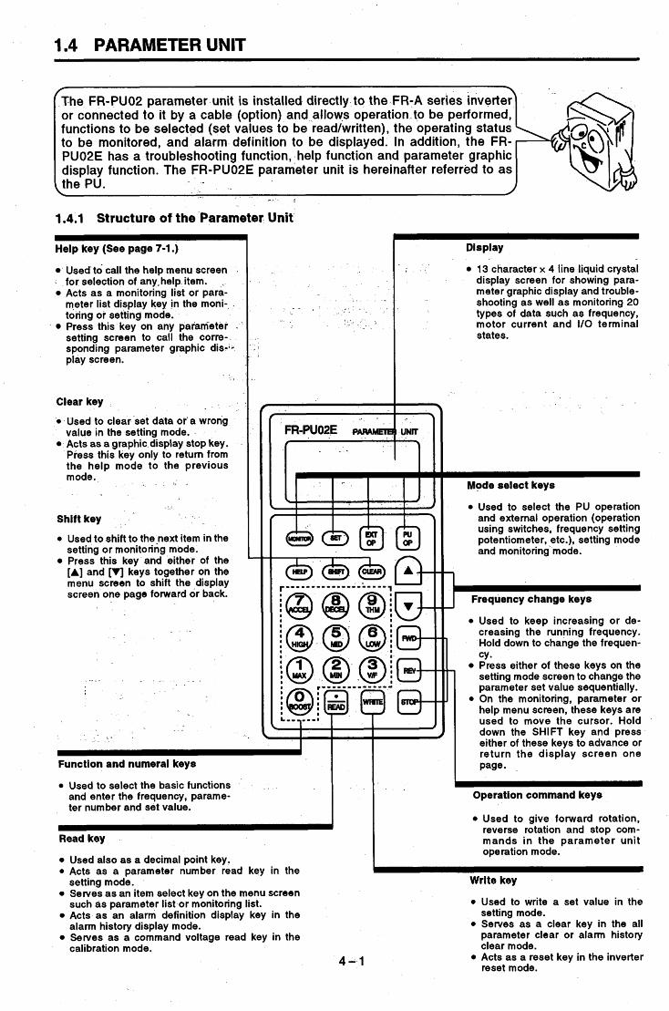
The FR-PUO2 parameter unit is installed directly to the .FR-A series inverter\ or connected to it by a cable (option) and allows operation-to be performed, functions to be selected (set values to be read/written), the operating status to be monitored, and alarm definition to be displayed. In addition, the FR- PU02E has a troubleshooting function, help function and parameter graphic display function. The FR-PU02E parameter unit is hereinafter referred to as the PU. - .
\ - 4
1.4.1 Structure of the Parameter Unit ~~
Help key (See page 7-1 .)
Used to call the help menu screen for selection of anyvhelp item. . Acts as a monitoring list or para- meter list display key in the moni- toring or setting mode. Press this key on any parameter . setting screen to call the corre- sponding parameter graphic dis-1- play screen.
Clear key
0 Used to clear set data or a wrong value in the setting mode. Acts as a graphic display stop key. Press this key only to return from the help mode to the previous mode.
. I ,
Shift key
0 Used to shift to the-next item in the setting or monitoring mode. Press this key and either of the [A] and ['I] keys together on the menu screen to shift the -display screen one page forward or back.
.~
Display
13 character x 4 line liquid crystal display screen for showing para- meter graphic display and trouble- shooting as well as monitoring 20 types of data such as frequency, motor current and I/O terminal states.
r"? L'
I
& & $ $ I I I I n I
c I I
I I '
Function and numeral keys
0 Used to select the basic functions and enter the frequency, parame- ter number and set value.
Read key
Used also as a decimal point key. 0 Acts as a parameter number read key in the
Serves as an item select key on the menu screen
Acts as an alarm definition display key in the
Serves as a command voltage read key in the
setting mode.
such as parameter list or monitoring list.
alarm history display mode.
calibration mode. 4-1
Mode select keys
0 Used to select the PU operation and external operation (operation using switches, frequency setting potentiometer, etc.), setting mode and monitoring mode.
1 J -Frequency change keys
0 Used to keep increasing or de- creasing the running frequency. Hold down to change the frequen- CY. Press either of these keys on the setting mode screen to change the parameter set value sequentially.
0 On the monitoring, parameter or help menu screen, these keys are used to move the cursor. Hold down the SHIFT key and press either of these keys to advance or return the display screen one page-
p"! -
Operation command keys
0 Used to give forward rotation, reverse rotation and stop com- mands i n the parameter unit operation mode.
~~
Wrlte key
0 Used to write a set value in the setting mode.
0 Serves as a clear key in the all parameter clear or alarm history clear mode. Acts as a reset key in the inverter reset mode.

P
i ' 3
b
i
1.4.2 Precautions for Using the Parameter Unit
When using the PU, note the following points to make proper settings and enter correct values. . . . ' - . -
instructions for operation performed from the PU
Operation from the PU is only valid when the [PU-OP] key is pressed with '0' (factory setting) set in parameter 79 or when PU operation or combined operation is se- -1ected in Pr. 79.
7 - - - I
In the monitoringmode, the running frequency cannot be set by direct setting (by entering the frequency directly from the key pad). To set the running frequency, perform step setting (change the frequency sequentially by pressing the [A]/[V] key) and press the [WRITE] key, or press the [PU Opl key after exiting from the monitoring mode.
mode 4 : -
~ S T F FWD PU ' I ~
- . f
Z I - r . . - 3 .
Exiting from monitoring mode
a D i R E C T L Y
Frequency 3 0 . 0 0 H Z setting screen
0-400
instructions tor monitoring
When the- motor is to be run in the PU operation mode, setting the running frequency and then pressing the start key [FWD] or [REV automatically switches the inverter
-to the monitoring mode. - .- -. . I
Instructions'for the operation modes
I f the [PU OP] (or [EXT OP]) key is pressed,, the mode cannot be switched when: , . " L I
(1) The motor is running; (2). The external operation start signal (across terminals
_ _ STF or STR-SD) is on; or -
' (3) The set value of the operation mode select paramel
When "0" is in the operation mode select parameter (Pr. 79), switching the inverter power off, then on or resetting the inverter switches it to the external operation mode.
ter (Pr. 79) is any of 1 to 5 and 7. . : . $
) _ I
instructions for the number of digitsband decimal point of an input value
An input value of up to five digits may be entered. If the value entered is in more than five digits, the most signifi- cant digit is ignored.
- -
r -
12345.6 =$ I-3 23456
(Entered) Ignored
- -
J,
* _
. I ;.
Jog operation cannot be performed when: (1) The motor is running; or (2) The jog frequency (Pr. 15) is less than the starting
frequency (Pr. 13).
4 --2

instructions for writing set values
Write the set values when the inverter is at a stop in the PU operation mode or combined operation mode. They cannot be written in the external operation mode. (They may be read in any mode.) Note that some parameters may be written in the external operation mode or during operation. See the following table: -
External operation
mode
PU operation
Write Enabled
setting" setting'
Pr. 51 to 56 "display. function' Pr. 158 'AM terminal function selection" .
Pr. 4 to 6 "three-speed setting". Pr. 24 to 27 'multi-speed setting' Pr. 51 to 56 'display function" Pr. 72 'PWM frequency
mode and combined operation
mode
- .-
setting" Pr. 51 to-56 'display function" Pr. 79 'operation mode selection" Pr. 158 'AM terminal function selection"
selection' Pr. 77 'parameter write Ail disable selection' Pr. 158 "AM terminal function selection' Pr. 900 'FM terminal calibration" Pr. 901 "AM terminal calibration'
(Example: Pr. 7 'acceleration time')
Setting Error 20000s
instructions for setting the running frequency
- @ When using the, [A][V]key-to set the frequency (step setting), the frequency may only be set within the range of the maximum and minimum frequencies.
Other instructions j s
e. When the input power is switched on (or the inverter is reset), the following message is given on the display of the PU for about 1 second. This message indicate that the inverter and FR-PU02 parameter unit are performing communication checks with each other and does not indicate an alarm. Note that if this message does not disappear in about 1 second, see 'TROUBLESHOOT-
. .
ING" (page 24-1).
cornms.. Error Inv. Reset ON
. . . .
The above message is also displayed when the control circuit power is switched on later than the main circuit power in a system where the control circuit is connected to a power supply separately from the main circuit. Similarly,- is displayed on the unit LED instantane- ously at power on but it is not an alarm. If this display is kept provided, see "TROUBLESHOOTING" (page 24-1).
- 4-3
1

--
1.4.3 Using the FR-ARW Parameter Copy Unit
Like the FR-PU02E, the FR-ARW parameter-copy unit can be installed on the inverter or connected to the inverter by a-cable, and allows operation to be performed, functions to be set, and operating status*to be monitored. (The [A] and ['I] keys are different in function from those of the FR-PU02E.) The FR-ARW also allows the parameters oftone inverter to be read in batches and easily copied to other inverters. - - -- Note that the parameters may only- be copied between the inverters of the same series. They cannot be copied between different models.
I
- _ - - _ - - - I - - - - I - - _ - 1
-. . 1.4.4 Using the FR-PUO1 Parameter Unit ' ' *
The FR-PUOlE parameter unit can be used by connection to thehverter by a cable (option). It cannot be installed directly to the inverter.
- .
For the use of the FR-PUOI E patameter .unit, 'not
With the power on, you can- When the FR-PUOlE parameter unit is being used, reset the not use the the FR-PUO1 E ~ I -+inverter once-in either of. the following methods, with the parame- and FR-PUOPE parameter ter unit connected by the cable. units by changing them alter- .Switch the power off once, and in more than 0.1 seconds, nately. . , . switch it on again.
- L .After connecting the reset terminal RES-SD for more than 0.1 ' seconds, disconnect - . them.-
Note: The inverter recognizes the type of the parameter unit at the time of reset or power-on and does not communicate with any parameter unit other than the one recognized.
e following points.
- -
r -j -
- .- I - _ . -. - ~ - * -.
* . 7 - - - . ' 1 - i
I . ' )
.
---_. - - -- - - _ _ - - 8
- . . * ; ' . +
* -
- . - . - L- -- " . - - _ - -
- _ . a _ .
- - -1- ~ --
_ _ . B L . . _ - ' t . - .
P
I
i
I
'2
i
i

The functions of the inverter are limited by the FR-PUOlE. See the function comparison on the right. . -
Frequency setting 0 to 400Hz Forward rotation, reverse rotation, stop PU operation, external operation, jog operation, PWextemal combined operation Output frequency, output current, output voltage, alarm display, frequency set value, running speed, motor toque, converter output voltage, regenerative brake duty, electronic overcu rren t protector load factor, output current peak value, converter output voltage peak value, input power, output power, input terminal state, output terminal state, load meter, motor exciting current, position pulse, cumulative operation time, actual operation time Enabled for all of Pr.0 to Pr. 159 and Pr. 200 to Pr. 231.
Pr. 90 to 96 cat5 be set. Pr. 900 to Pr. 905
. . . . . . . I _
. _ . . .
Batch clear is performed using 'ALARM HISTORY CLEAR' in 'the help mode. Parameter clear (calibration function not cleared) or all parameter clear (calibration function cleared) can be set. OV1 to OV3 PUE, RET, CPU
Function
Operation setting function
Operation node setting
Monitoring function
Parameter settting function
Auto tuning
Calibration function
Alarm display clear
Parameter initialization
Alarm display
0000 oeoa
FR-PUO1 E Parameter Unit
As on the left
As on the left
%put frequency, output :urrent, output voltage, alarm jisplay The other items cannot be n oni to re d .
.-
. . ,
Limited to Pr. 0 to Pr. 79. Disabled for the gear backlash compensation and 5-point flexible V/F characteristic parameters. Al l settings disabled. c1 to c5 Note that C1 cannot be used when any of 101 to 121 (AM terminal) is in Pr. 54. Pr. 901 (AM terminal calibration) cannot be set. Batch clear is performed by pressing the CLEAR key when a monitoring error is displayec All parameter clear (calibration function not cleared) can only be set.
.OVT The alarms indicatec
. p ~ on the left are dis- I Dlaved in this wav.
In addition, the following functions are not available for the FR- PU01:
Parameter initial value list Parameter change list
0 Troubleshooting Inverter reset from the parameter unit Graphic display of parameter functions
4-5

- .- - - - - - _ - - _ .
1.4.5 Using the FR-ZRW Parameter Copy Unit
The FR-ZRW parameter copyunit can be usedby connection to the inverterby a cable (option). Like the FR-PUOIE, the FR-ZRW limits the inverter functions. In addition, the function of reading and copying a batch of parameters to another inverter cannot be used.
.-__ .... - . . . . . . . . . . .. - . . __ .. . . . . . . .
. . . . . . . - . . . . . . _ _ - .
. . . . . . . . _- _ _ _ . _. - . . . . . . . . . .
. . . . . . . __ - . - . . . . . . . . . . . . . .
..... _- .. - ..... . . . . . - ......
. . . . . . . - . - . - . . . . . .
-. . . . . . .- . . . . . . . . . . . - . - .. . _. .- -
. . - _ . . . . . . . . . . - . _- . . . . . . . . . -. . . . . I . . . . .
... ._---I . . - _ . _ . . . . . . . . . . . . . . . . . . . . . - - ......
_. . _ . _. - - ~ . . . . - . .... - . - . . . . . . . - ........
. . . . . . . . . . . . . . . _--I-.._ .. -_ .
-._.- . . . . . . . . - . . . . . . .
- . . . . . . . . ........ .- - .. , ._. - - -. . -.
- - - . . . . . . . . I._._ - . ............
4-6

MEMO

. . . I . .-
. . . .
. - I *
, ' * _ .
2. OPERATION . . # : I , -
. . . . . . . . . . . . .- -
r . . / . This chapter offers detailed information on the "opera- tion" of the FR-A201E "inverter with built-in power return function". Always read the precautions and instructions in this
1 .. * - .. " . . . . . . . . . . ..,$.. , .
chapter before using the inverter. . . ". .-
A . . ' - ' , - . - ~ ' . . . L. 3;) : , . . . .'
. . . , - 1
- 3 . . \ , _ . -. <
I ,
...
- 1 . . . . 1 , .
,a.
. -
. . . . . . _ 1
.. "
t -
., " . . * '. . . . . . . .
. . .I.
f.

2.1 OPERATION
Select the appropriate mode for the application and operating conditions and prepare necessary instruments and parts. For operation modes, refer to page .
Start signal
Frequency setting signal Switch, relay, etc.
0 to SV, 0 to lOV, 4 to 20mA DC signals from a potentiometer or outside the in- verter
switch T, J
Operation using the frequency setting potentiometer and start switch provided externally
1. External operation mode
1 The inverter is operated under the control of external opera- tion signals connected to the terminal block.
Potenti- ometer
Note: 1. Not only the start signal but also the frequency r setting signal are required to run the inverter.
Parameter unit
Cable (FR-PUO2E) (See page 28-6)
(FR-CBL) (See page 28-9)
1 Use this cable when the pa- rameter unit is held in hand to perform operation, for ex- ample.
Inverter I
Start signal Switch, relay, etc.
0 to SV, 0 to lOV, 4 to 20mA Frequency setting signal
signals from a potentiometer or outside the inverter
(FR-PUO2E' (See page 28-6)
(FR-CBL) (See page 28-9)
f Use this cable when the
Parameter unit
Cable
) parame-ter unit is held in hand to perform operation, for example.
potentiometer Start switch J
*: "PU" stands for the parameter unit.
5-1
Use the PU to start. Direct setting of frequency Step setting of frequency Jog operation Hold down the FWD or REV rotate the motor.
2. PU operation mode The inverter is operated from the keypad parameter unit.
key to
of the
I This mode does not require the operation signals and is use- ful for an immediate start of operation.
Use the external signal Use the operation command keys of the PU to start.
Use the PU to set the Use the external frequency setting potentiometer to set the frequency.
to start.
frequency.
3. ExternaVPU combined operation mode
The inverter is operated with the external operation and PU operation modes combined in either of the following two methods.
1) The external signal is used as the start signal and the PU is used to set the frequency.
2) The operation command key of the PU is used to start and the external frequency setting potentiometer is used to set the frequency.

I
items according to the load and operational specifications. For simple vari- able-speed operati-on or the like, use the inverter with the factory setting. For more information and the explanation of the other parameters, see page 9-1.
p9 Pr. 905 "frequency setting current gain" ~
Pr. 1 "maximum frequency" -~ - - ~
Parameter Factory Setting Pr. 903 "frequency setting voltage gain" Pr. 905 "frequency setting current gain" Pr.-l "maximum frequency"
60Hz at 5V (or 1 OV) DC OHz at 4mADC, 60Hz at 20mADC Up to 120Hz
~ .- -.
- _
- -.
Note: When the frequency meter is connected across terminals FM-SD to monitor the running frequency, the output of terminal FM is saturated if the maximum output frequency reaches or exceeds lOOHz, with the factory-set value unchanged. Hence, the setting of Pr. 55 "frequency monitoring reference" must be changed to the maximum output frequency. (See page 9-25.)

Setting of maximum fre- quency
Pr. 1 "maximum frequency' . -
Application
For constant-toque- oads 1e.g. conveyor, carrier) For variab1e:torque oads 1e.g. fan, pump)
For lift . . <
Applied load selection switching function
.
Setting of minimum fre- quency
Pr. 2 "minimum frequency"
Remarks - . set
Value 0
(factory setting)
1 - -
Boost for forward rotation ... Pr. 0 set value Boost for reverse rotation ... 0% Boost for forward rotation ... 0% Boost for reverse rotation ... Pr. 0 set value
. Terminal RT ON (Note) . As in constant-toque loads.
As in no boost at reverse rotation for lift. No boost for reverse rotation
As in constant-toque loads.
As in no boost at fotward rotation for lift. No boost for forward rotation
-*
4 0 Terminal RT OFF
Terminal RT ON (Note)
5 .Terminal RTOFF
Setting of electronic overcur- rent protector
Pr. 9 "electronic overcur- rent protector"
Selection of applied loady 0 Pr. 14 "applied load selec-
tion" . . -
Set this parameter to define the upper limit of the output fre- quency or to perform operation at a frequency above 120Hz. Change the setting of this parameter only when the frequency must be limited in addition to the setting of the above-mentioned "frequency setting voltage (current) gain" which allows the fre- quency to be restricted to below the set value. . ~ Factory setting: 120Hz ~ .
Use this parameter to specify the lower limit of the output fre- quency. When ttie minimum frequency has been set, merely turning on the start signal starts the motor running at the: set frequency (if the frequency setting is OHz, no rotation will hap- pen). -
Factory setting:.OHz
The factory setting is the rated current value of the inverter. When changing the set value, set the 50Hz current value given on the motor rating plate. -
Note: The operation characteristics, which are based on the Mitsubishi .standard squirrel-cage motor, do not apply to a special motor. For a special motor, provide a thermal relay to protect the motor. (A constant-torque motor can be selected by the setting of Pr. 71.)
Allows the optimum output characteristic (V/F characteristic) to be selected for application and load characteristic.
~
Note: When terminal RT is ON, the second control functions (second acceleration/deceleration time, second torque boost and second base frequency) are selected.
5-3 ,

i
Pr. 17-Set Value
I
JOG/OH Terminal Function MRS Terminal Function OH (external
Jog Mode thermal relay N/O Input N/C Input
i
0 Pr. 8 "deceleration time" Pr. 44 "second acceleration
Pr. 45 "second deceleration /d ec e I e rat i o n ti me I'
time" . I + -
I
Parameter Factory Setting 7.5K and down ....... 5 seconds, 1 1 K and up 15 seconds 7.5K and down 5 seconds, 1 1 K and up 15 seconds
5 seconds
9999 (same as the value set in Pr. 44)
Pr. 7 "acceleration timen
Pr. 8 'decelerqtion time"
Pr. 44 "second acceleration /deceleration time" Pr. 45 "second deceleration timeo
.............. .......
.............. i
I
Selection of external thermal relay input o_Pr. 17 "external thermal
relay input"
When a thermal relay is installed outside the inverter or the motor - contains a temperature sensor, this parameter switches the func- tion of the JOG/OH input terminal to OH (external thermal relay input). -
I
When an inverter once used is to be used again
i
It is assumed that the set values of the parameters may have been changed according to the operational specifications. Before start- ing operation, initialize ( the parameters (return the parameter values to the factory setting). Initialization can be made by per- forming parameter clear operation using the parameter unit. (For the operation procedure, see page 7-1 1 .) Note that the following parameters are not initialized by the parameter clear operation. For these parameters, read their set values and change them to the required values, or perform-parameter all clear operation to return to the factory setting.
Pr. 900 "FM terminal calibration" Pr. 901 "AM terminal calibration" Pr. 902 "frequency setting voltage bias" Pr. 903 "frequency setting voltage gain" Pr. 904 "frequency setting current bias"
0 Pr. 905 "frequency setting current gain"
F I
5 -4

2.1.3 Pperation Mode .
(The inverter has three operation modes: "operation using the external inpu signals" (external operation mode), "operation using the PU" (PU operation mode), and "combined operation using the external input signals and PU" (comb-ined operation mode). -
Factory-set operation mode
. When the input power is switched on (or the inverter is reset), the inverter is set
- to the mode of "operation using the ex- ternal input signals". Therefore, as soon as the input power is switched on, the inverter is ready for operation using the external input signals. In this state, turn the start signal (across STF, STR and
. 0 Operation is performed
from the frequency setting
0 Started from the PU. 0 Direct setting of the frequency
key to run the motor Com bined operation
0 Start signal is the external signal. 0 Frequency is set from the PU.
0 Started by the operation command
0 Frequency is set from the external frequency setting potentiometer.
W Fixing the operation mode
The operation mode at power on may be limited, e.g. operation from the PU is enabled at power on without switch- ing the operation mode with the PU's mode select key. For full information on the setting pro- cedure, see page 5-7.
5-5

2.1.4 Selection of the Operation Mode _ _
The inverter is factory-set to allbw the-operation mode to be switched between "external operation" and "PU operation". At power-on, the inverter is placed in the "external operation" mode. Use the PU to switch to the other operation mode.
f Description
Start 'Signal Set Running Frequency Setting
3 0 Direct setting and [A] 0 STF [VI key setting STR
Parameter unit Terminal signal
Terminal signal Parameter unit 0 0 to 5VDC across 2-5
0 to 10VDC across 2-5 4 to 20mADC across 4-5
0 Multi-speed selection (Pr. 4 to 6, 24 to 27)
0 FWD key 0 REV key
4
I 0 Jog frequency (Pr. 15)
Switching from the external ........................ Check that the external input signal is off (across STF or STR and SD). Then, press the [PU OP] key to switch to the PU operattion mode, the frequency setting screen is dis-
operation mode to the PU- I operation mode
. . .
0 - 4 0 0 -- - - - Frequency setting screen
_ _ - .__
Switching from the PU op- ....................... Check' that the external input signal is off (across STF or STR and SD) and-that the operation com- mand indication is 'I---".
eration mode to the external operation mode
Then, press the [EXT OP] key to switch to the exter- nal operation mode, "EXT" is displayed as the opera- tion mode indication. - . -
7 t Operation command indication Operation mode indication
- . - Switching to the combined .............. 1 ........ Change the set value of Pr. 79 "operation mode operation mode
I 0.0O"z I t
* . Operation -mode indication
selection" as indicated below. (For more information on changing the set value, see page 8-1.) "PU+E" is displayed at the operation mode indica- tion.
5 - 6

~ ~~
Note: If the operation mode cannot be switched properly, check the following: 1. External input signal Check that the signal is off. If it is on, the operation mode cannot be
switched properly. Look for STF or STR on the PUcdisplay. Check the set value of Pr. 79 'operation mode selection".
(across STF or STR and SO) -. 2. Parameter setting
. '
. > ' .j . .. - * - ~
When the set value of Pr. 79 'operation mode selection" is '0' (factory setting), the inverter is put in the external operation mode at input power-on. Press the [PU OP] key to switch to the PU operation mode. For the other set values (1 to 5, 7, 8) , the operation mode is limited accd rdi ng I y .
3. Limitation of the operation mode
i . , -
I
The currently selected operation mode, operation status, etc. are displayed at the bottom of the display screen of the parameter unit.
Operation mode indication PU: PU operation NET: Computer, PC link operation
- - - - EXT:: External operation PU+E: PUhxternal combined operation
0 PUj: PU jog operation PRG: Programmed operation EXTj: External jog operation
*Operation status indication FWD: Forward rotation in progress REV: Reverse rotation in progress
JOGf: Jog forward rotation in progress JOGr: Jog reverse rotation in progress
STOP: At a stop I I
Operation command indication STF: Forward rotation STR: Reverse rotation
---: No command or both STF and STR 'ON'

- - - . _
2.1.6 External Operation Mode (Operation using the external inputcsignals)
(1) Standard operation Operation procedure (Operation at 60Hz)
/
...... Switch the power on and make sure that "EXT" Is shown at the
I f i t is not shown, switch to the ex- ternal operation mode in accord- ance with page 5-6.
- operation mode indication.
Note 1 : I f the forward and reverse ro- tation switches are turned on together, the inverter will not start. Also, if these switches
. are turned on together dur- ing operation, the motor is decelerated to a stop.
I ...... Turn on the start switch (connect terminals STF or STR and SD). (Note 1) The operation command indication changes to 'STF" or 'STR".
/ . I ...... Slowly turn the potentiometer
/ (frequency setting potentiometer) full clockwise. The frequency shown on the display increases gradually to 60Mz, and the I
operation status bndication changes . to output indication (FWD or REV).
.. 1 .- , :
...... Slowly turn the potentiometer
. . (frequency setting potentiometer) counterclockwise. (Note 2) The frequency shown on the display decreases gradually to OHz.
~
' The motor stops running.
...... Turn offthe start switch Forward rotation (disconnect terminals STF or STR
Note 2: If the start switch is turned off with the potentiometer in the full clock- wise position, the motor is deceler- ated to a stop. The DC dynamic brake operated at this time gener- ates high-frequency noise immedi- ately before the stop, this is not a fault.
~~ I Potentiometer rating, 1 or 2W, 1kQ I - -
Note 3: Do not switch power on
: . command (STF, STR when the operation
terminal) is on. Switch on the operation com- mand (STF, STR termi- nal) after 1 second after power-on.
5 - a

(2) External jog operation Keep the start switch on (connect terminals STF or S I R and SD) to perform operation, and switch it off to stop. For details of chai
0 Operation procedure (Operat
/
iging the parameter setting, see page 8-1. ion at 8Hz)
...... Switch the power on and make - sure that "EXT" i s shown at the
operation mode indication. I f i t is not shown, switch to the exter- nal operation mode in accordance with page 5-6.
~~~
Note 1 :The frequency and accel- eration/deceleration time for jog operation can-be set
+ in the following parameters. <Factory settings .Pr. 15 "jog frequency" ...
' 5Hz . .
oPr. 16 "jog acceleration/de celeration' ... 0.5 seconds
...... Press the [PU OP] key-to . switch to the PU opera- tion mode and use para- - ~ - . meter 15 "Jog frequency"> to set. (Note 1) After the setting is com- plete, press the [EXT OP] key to switch to the external operation mode.
i
..... Turn on the signal across termi- .
nals JOG and SD (connect these terminals). The jog operation mode is selected and the operation mode indication changes to "EXTj".
I
' > 3. Jog oper i t i i n mode ieliktfon . Y
. .
...... Turn on the start switch (connect termi- nals STF or STR and SD). (Note 2) Keep the start switch on to perform opera- tion, switch it off (disconnect) to stop.
...... Switch off the signal across termi- nals JOG and SD (disconnect these terminals). The inverter exits from the jog opera- tion mode and returns to the ordinary external operation mode.
Note 2: If the motor does not run, check Pr. . _ _ 13 "starting frequency". If the set
value-is less than the starting fre- quency, the motor does not start. 1
rc! .__
5-9

2.1.7 PU Operation Mode (Operation using the PU) * -
(1) Standard operation
- 0 Operation procedure (Operation at 60Hz) By repeating steps 2 and 3 during motor operation, speed can be changed.
- -
,., . /
I <Direct setting>
,.....Switch the power on, press the [PU OP] key, and make sure that the frequency setting screen is shown on the display. . _ If it is not shown, switch to the PU operation mode in accordance with page 5-6.
Note 1:After pressing the [PU OP] key, enter the frequency di. rectly with the numeral keys. This setting is not available in the monitoring
. mode. Press the [PU OP] key to leave the monitor- ing mode before setting.
. .
. - . . . ...... Set the running frequency to 6OHz.
/ I .Direct setting (Note 1)
. I
...... Press the [WRITE] key.
......-P ress the [FWD] or [REV] key. The motor starts running. The in- verter is automatically placed in the monitoring mode and the state of the output frequency is dis.played.
...... Press the [STOP] key. ! The motor is decelerated to a stop.
Note 2: Press the [A]/[V] key to keep the frequency changing. Hold down the [A] (or [VI) key to change the fre- quency. At the beginning, the fre- quency changes slowly and this may be used for fine adjustment.
I J
Note 3: Step setting can also be made during inverter opera tion. However, if the [A] (or [VI) key is pressed in the monitoring mode, the frequency-does not stop changing when the key is released and rises (or falls) further. (Since the [A] (or [VI) key changes the set frequency, switch operation does not match
5-10

(2) PU jog operation Hold down the [FWD] or [REV] key to perform operation, and release it to stop. For details of changing the parameter setting, see page 8-1. Operation procedure (Operation at 8Hz)
Note 1 :The frequency and accel- eration/deceleration time for jog operation can be set in the following parameters. <Factory setting> .Pr. 15 'jog frequency" ... 5HZ
.Pr. 16 'jog acceleration/de- celeration" ... 0.5 seconds
...... Switch the power on, press the [PU OP] key, and make sure that the frequency setting screen is shown on the display. If it is not shown, switch to the PU .
...... Use parameter 15 "Jog frequency" to set. - -
. . . . . . . Press the [PU OP] key, then the
The jog operation mode is selected and the PU JOG frequency setting screen is' shown on the display. To change the frequency, enter the nu- merical value and press the [WRITE] key.
[SHIFT] key. , .
...... Press the'[FWDl or [REV] key. - - The display changesto the monitor screen. Hold down the key to perform operation and release it to stop. (Note 2)
. - ...-... Press the [PU OP] key.
13 "starting frequency'. If the set value is less than the starting fre- quency, the motor does not start.
~~
. .
. _ . . . , . -
The inverter exits from the jog opera- tion mode and returns to the standard PU operation mode. To return to jog operation mode, press the [SHIFTJ key.
5-11

b
I
3
F
2.1.8 Combined Operation Mode (Operation using the external input signals and PU)
(1) Entering the start signal externally and setting the running frequency from the PU (Pr.
The external frequency setting signals and the PU's FWD, REV and STOP keys are not accepted. For details of changing the parameter setting, see page 8-1.
79=3)
Operation procedure (Operation at 60Hz)
...... Switch the power on. I I
........ Set "3" in Pr. 79 "operation mode selection". The combined operation
/ I mode is selected and the
Note 1 : If the forward and reverse rotation switches are turned on together, the inverter will not start. Also, if these switches are turned on- together during operation, the motor is de- celerated to a stop.
Note 2:After pressing the [PU OP] key, enter the frequency directly with the numeral keys. This setting is not available in the monitoring mode. Press the [PU OP] key to leave the monitor- ing mode before setting.
operation mode indication - 1 . * ~- on the display changes to -
r -
I
...... Turn on the start switch (connect I Forward rotation / I terminals STF or STR and SD).
(Note 1) * The operation command indication
changes to "STF' or 'STR' and the operation status indication changes to - output indication (FWD or REV).-
-- . i . 1
...... Using the PU, set the running frequency to 60Hz. '
.Direct setting (Note 2)
.Press the [PU OP] key to call the frequency setting screen, and perform step set_ting. (Note 3)
...... Press the [WRITE] key. The [WRITE] key must be pressed, otherwise the frequency is not stored into memory.
Note 3: Press the [A]/[V] key to keep the frequency changing. Hold down the [A] (or [VI ) .key to change the frequency. At the beginning, the fre- quency changes slowly and this may be used for fine ad- justment.
6. Stop
Forward rotation / Reverse rotation Lop
O/
...... Turn off the start switch (disconnect terminals STF or STR and SD). The motor is stops running.
:5 - -12

(2) Entering the running frequency externally and start and stop from the PU (Pr.794) For details of changing the parameter setting, see page 8-1. Operation procedure
Note 1 :The starting terminals ...... Switch the power on. (STF, STR) of the inverter
are invalid. The inverter cannot be started if the [FWD] or [REV] key is pressed and the level of the frequency setting signal is then raised.
- - -
...... Set "4" In Pr. 79 "operation mode selectlon". The combined operation mode is selected and the operation mode indication on the display changes to
...... Enter the running frequency signal (select the multi-speed signal or . turn the frequency setting potentiometer).
...... Press the [FWD] or [REV] key. (Note 1) The motor starts running. The state of the output frequency is shown on the display.
...... Press the [STOP] key of the PU. The motor is decelerated to a stop.
-5-13

- -- - - -_- - . - - I _ - -
(3) Entering the start signal and multi-speed signal externally andsetting the multiple speeds
Perform this operation in the external operation-mode-with ''+ (factory setting) set in Pr. 79 - -from the PU - - -
--- "operation- mode selection". . ~ - - . - _ - -
For details of changing the parameter setting, see page 8-1. 0 Operation procedure - - - _ _ - _ __ - _I - -
...... Switch the power on;
I
0 . .- -
_- - -
&...... Select the multi-speed I - - - _ _
High speed
signal requlred for-. - Operation (connect terminals RH/R M/R L-SD).
- -
Note 1 : If the forward and reverse -- rotation switches are
turned on together, the in- _. verterwillnot start. Also, i f
these switches are turned on together during opera- tion, the motor is deceter- ated to a stop.
Note 2:The set values of the-multi- ple speeds not being used
- . can also-be cka-nged dur- ing operation. (See page 9-6.)
.....-. Turn on the startswitch (connect . ~ -
. . . _._
- . . - . . . . - . . ..
Forward rotation / .
- -
terminals STF or STR and SD). (Note 1) The operation command indrcation - changes to "STF" or "STR" the operation status indication changes- to output indi- cation (FWD or REV), and the motor .starts rotating. - - - - - - _ _ _ . _
- - - - - I - - -- __ ....... Using the PU, change the current
multi-speed frequency. When high speed has been selecte3- (RH-SD connected), changing the value of the "three-speed setting-
-
- - --
~ _ _ - - - - -
(dlsconnect terminals RHIRMIRL- SD) and turn off the start switch
rward rotation --
_ _ * . - - .
- . . _. ... - . - - .- -. - - - .. . ... . . . . . - .- - .- . . . . - . . . - . _- -- . . . . . - . -. . .
5-14

MEMO
. . . . _. , ,_ -
. . . . / I . . , . I
. . _- - . - t
, . .
I . . ~ .- . . . . .
- . (7 L
* -

I
. . . . . . . . . . . . . . I. . . " _. . -, . . ,. - , , . - - .
, . . .. I .I. ,, ,. ' . , * I . ;, . 1 2 : i: . . . . . .- L
, . _ . 3. PARAM& i'ERS
This chapter provides detaiiedinfoimati'on on the "pa-
..' . . : '.* . " . - - !
.. i -
t d -.. * d . / 5 - I , - - .
. . . . . . - . . I . -, I . -.** :- ..+ r*: . . : ,L" .. -.*. X '
:-i . . . . . . . . . . ~ .. ' . ., 1. ;.; ,. ~ '-':I .* I I . . 1 . .
. I
. . . . *. ' . / . /
: . 'El . t l . . ?
1 .
' . . . . .
. " I :, rameters" of the FR-A201 E "inverter with built-in po we r re t u rn f u n c t ion " .' .Always read the precautions and instructions in this
I &. .> . I -.* 4 . * . T i i' I,'.
. I . :., ~. t . .* ' . . . . . * . . r i , r * r : ' ,
. I -. chapter before using the inverter. - . ' . . . . . . . . * . 1. I., , , - , . . * > : ' I i . < f b I, ' :a.
3 ' I , '
3.1 M 0 N IT0 R I N G F U N CTI 0 N ............................................ i .A ...... 6 - I '. 3.2 hELP FU,MCTION .................. :...r..d..l ................................. ~ ....... 7 - 1 3.3 S E T ~ ~ N G AND CHANGING THE VALUES
I
r' +
: *% . . . . - .I- ."
. IN :THE PARAMET'ERS ........................................... ...... B - 1 3.4 PARAMETE'RS .............................. ~.~.-W..~....b........~..~~.~...~*~.~~...~~.. 9 - 1 3 . 5 I NV E RTE $? . R E s ET .............. m," .......... i. ................................... -1 0 - 1
. . . . * . ., 8 . . . .
L L
. . I . . r , . . . '
' . I,
I . ,. - - . . I .
I ,
. . . . . . . . I .
i: .
. I
" 1 .
. . . . .

3.1 MONITORING FUNCTION
PU level meter
Setting Pr. 53 on the PU allows selection from 15 types of data. (See page 9-23.)
Factory setting ... Pr. 53 = nlo Output frequency indication
1 Inverter LED display
Setting Pr. 51 on the PU allows
page 9-23.) Factory setting .... Pr. 51 = "1"
I-] selection from 16 types of data. (See 1 r r 1 . 1 I 1 1
Output frequency FR-PU02E PARAUETW UNIT indication
+
and running speed.
Switch the power on or press the [MONITOR] key.
'A <=? (Output frequency
monitor)
(Output current monitor)
(Output voltage monitor)
(Alarm code monitor)
--- STOP EXT
(Selective monitor)
STOP M T
ALARY HISTOR I <READ> lo@o
~
Note: 1. By pressing the [WRITE] key on any of the monitor screens shown on the left, that screen is given the first priority (first prior- ity screen). When the [MONITOR] key is pressed immediately after power-on or in the setting or other mode to enter the moni- toring mode, the first priority screen is dis- played first.
2. When "17" (load meter) or "18" (motor ex- citing current) is selected in Pr. 52, the "output current monitor" shown on the left is switched to the "load meter" or "motor exciting current". When "1 9" (position pulse) or "20" (cumulative operation time) is selected in Pr. 52, the "output voltage monitor" is switched to the "position pulse" or "cumulative operation time".
6-1
0 @ 0 Monitor selection
1 Selection can be made from 20 types of data. (See page 6-2.)
1 UVT 8 2UVT 6 a 7 4 1 )

3.1.2 Selecting the-Another Monitor Item in the Selective Monitoring Mode . >
2) Press the [HELP) key. ..... The monitoring list is displayed.
pi!J!J I _
; I
1)
3)
3) Hold down the [SHIFT] key and press the [VI key three ...... Hold down the [SHIFT] key and press the [VI or [A] key to advance or return the screen one page. .times, and without pressing the [SHIFT] key, press the [VI _ .
key twice. (Move the cursor I to signal In.)
5) Press the [WRITE] key. ... The screen in step 5) is set as (Note 2) the first priority screen.
4) Press the [READ] key. .... The screen shown on the right is (Note 1) displayed.
...... Subsequently press the [SHIFT] key to call the. other monitor screen.
Note: 1. Since the selective monitor screen is not the first priority screen in the above step 5) where the [READ] key has been pressed, the selected data is erased from the memory as soon as the power is shut off or the other operation mode (such as external operation) is selected. In this case, the selective monitoring mode must be selected again in the above procedure. When the first monitor screen has been set by pressing the [WRITE] key, the selected data remains intact in the memory.
2. In step 6) where the [WRITE] key has been pressed in the above setting example, the "I/O terminal states" selected here are first displayed with priority when the other operation mode is switched to the monitoring mode. To give first priority to other data, press the [WRITE] key with the monitor screen being displayed. The first priority screen then switches to that monitor screen.
6-2

Selecting any of the monitoring items "load meter", "motor exciting current", "position pulse" and "cumulative energization time" When the "load meter" or "motor exciting current" has been selected, the output current monitor screen is switched to a corresponding screen. When the "position pulse" or "cumulative energization time" has been selected, the output voltage monitor screen is switched to a corresponding screen. When any of these four items has been selected, the output current or output voltage monitor screen cannot be used.
- _ . .
When "load meter" or 'mo- tor exciting current" moni-
this screen is switched.
When the 'position pulse' or 'cumulative energization time"
this screen is switched. . , tor has been selected, monitor has been selected,
SHIFT p -- ---- - - - - ---- - - - 0 First priority screen .
SHlk r - - - - - - - - - - - - - - - 0 0.0"
STOP EXT STOP EXT (Output frequency monitor)
(Selective monitor) (Alarm code monitor) ' I I I
- _
Selecting "current monitoring" or "power monitoring"- Note that a current less than 5% of the rated current of the inverter cannot be detected and displayed. Also note that the electronic thermal relay does not operate at that current. For motor protection, examine the use of an external temperature detector or the like. Example: When a small motor (0.4kW motor). is run by a large-capacity inverter (5.5kW), power
monitoring is inactive.
. . 0 -
. .
6-3

- -
3.2 HELP FUNCTION
b
>
1
i
> I
i
>
1
' The FR-A201E inverter has a help function to assist you in performing
L following.
monitor mode
. . ',. - - . .
. I
. . . . . , I , .
.. . _ .
Resetting the inverter
.-.- ,
- . - . . -. .
In addition, press the [HELP] key in any of the PU operation modes to call a guide to the operation procedure. Press the [HELP] key for help when you-do not know what to do.

- - 3.2.1 -Definitions of the Help Function Displays
t
Press twice.-
1MONlTOR 2 PU Oper 3 Pr.List 4 Pr.Clear 5 Alarm Hist 6 Alarm Clear 7 Inv.Reset 8 TIShooting .
-- 1 Frequency ............,, 2 Current .................-, 3 Voltage ................. 4 Alarm ~i~ ....... 1
5 F Command .........-, 6 RPM ...................... 7 Shaft Trg ..............,, 8 DC Link ................ 9 Br Duty % ............
10 Therm OL ............--. 11 Peak ...................... 12 DC Peak V ...........- 13 IP Power .............- 14 O/P Power ........... 15 IP Signal ............. 16 O P Signal ...........
Output power (power currently being used on the output side) [kw ONOFF states of the input signals (STF, STR, etc.) ".ON 0 OFF ONOFF states of the output signals (STF, STR, etc.) ". ON 0 OFF
Frequency [Hz] Current [A] Voltage [VI Error definitions (See Section 22-1 .) *When more than eight alarms have occurred, the earlier ones are cleared. Frequency setting (Enter the set frequency) [Hz]
Motor torque (generated by the motor under magnetic flux vector control) --. Running speed (indicates the motor speed or travel speed) [r.]
[%I -, Converter output voltage (DC voltage in the converter) [VI --. Regenerative brake duty [%]
Electronic overcurrent protection load factor [%] Output current peak value [A]
output voltage) [VI , Converter output voltage peak value (maximum value of the converter
(7 -. Input power (power currently being used on the input side) [kw -
Press twice.
........... ......
1
2 PU Oper 3 Pr.List
PU operation mode directly set from the JOG operation mode
ten-key
HELP 0 Trq.Bst1 - READ
1 Setting MODE ....... 4 SElTlNG MODE 4 5 1 Max.f Set Pr.NO.
For Pr.List .................... READ 2 Pr.List 6 3 Set Pr.List ............. - <HELP> 2
7 4 Def. Pr.Llst ............ -- @ to
' READ
8 I I I ::: Values in each parameter list
can be changed.
/," 4096
Pr.914 -
Current status
... %
0 to 30
DEF.Pr.LiST Pr.0 6.0
Graph display
~ E A D I Pr.1 120.0 I 1 p:: I O.OO
i3
7-2

I Press twice.
1
2
3 4 Pr.Clear ............... 5 Alarm Hist .......... 6 Alarm Clear ........ 7 Inv.Reset ............ 8 TIShooting
READ
--
WRITE ............. 2 Clear All .............
CancekCLEAR>
* 1 M.NotRun - 4
2 M.Spd Error 3 M.A/Dec Err
3 Clear None .........
M.NOT RUNNING VFSetting STF, STR Error? both are OFF , See Pr.3,14,
or ON 19.47
Clear Pr. Executing
I I
Exec <WRITE> I CancekCLEAR> . I
5 Return to the previous screen.
I Error definltions (See Section 22-1) 'When more than eight alarms have occurred, the earlier ones are cleared.
4 ALARMCLEAR READ I IExec <WRITE> I CancelcCLEAR> 1 -
INV.RESET Exec <WRITE>
. -
. . - .
. .
CancelcCLEAR> I - fAssumed cause1
14 M.Curr. High i
Inv.Output
-A-V <SHIFT>
- -
Set S
0 - Hz 1 Set S
Inv.Output . Hz
A- V -
7-3

- 3.2.2 Help Function Menu I -
Press the [HELP] key twice in any operation mode to call the help menu, with which various functions can be executed. (See page-7-2) ~ , .
Menu screen page 1 I - -_ -
- - * - - - - - I - -__ -~ ~ " _
I
2 PU Oper 9 Pr. List 4 Pr. Clear B
Press [SHIFT] and [V I together to proceed to the next page.
Menu screen page 2-
Displays the monitoring list and'allows the monitor screen to be changed and the first priority screen to be set.
=ct the PU operation mode and' PU-assisted' jog operation mode via direct input (direct setting from the ten-key pad) and how to operate the keys.
. . - -
' 0 ' - A
- * - _ ->
< - , L
- - _ 7 .
DisplaysJhe parameter menu and allows any of the following four items to be selected and executed: ,
r - - _ _ 1 Setting - - i
- . - . . 1 . - .r. 2 Pr. List - 3 Set Pr. List 4 Def. UPr. List
Displays the parameter menu and allows any of the followingJhree items to be selected and executed:
I - - > J : 1 Clear Pr.
2 Clear All 3 Clear-.None . -'
f
8 Alarmclear 7 inv. Reset 8 T/Shooting
IS 6 Alarm Htst @I ......
. . . . .
Press any of [MONI- TOR], [SET], [EXT OP] and [PU OP] to switch to the corresponding _ _ mode.
Displays the history of eight past alarms.
Clears alC-the alarm history. ;
.. e " . i . -
Resets the inverter.
The inverter displays the most likely cause of mismatch in inverter operation with operation/setting or the cause of inverter fault.
7 -4

i
5) Press the [READ] key. .... The monitor screen specified by Wl the cursor is displayed. ......- After pressing the [READ] key,
press the [WRITE] key to set that monitor screen as the first priority screen.
i
3.2.3 Operation Procedure for Help Function - ,
. . . Displays the monitoring list and allows the monitor screen to be changed and the first priority screen
J
to be set.
0 Operation procedure 1 (To call the monitoring list from the help function menu) - Display
I f
.-
1) Press the [HELP] key ...... The help function menu is called. twice in the monitor . mode.
* -
I
I I 1
2) Make sure that the cursor (e) is located at ‘1 MONITOR..
- .. -. I ...... If not, move the.cursor with the
[A] [VI key. 1 - 7 1
1 - - _ _ 1)-
c 5)- 3) Press the [READ] key. .... The monitoring list is called.
i
4) Press the [A] or [VI key to move the cursor (9) to the required item
L 1
[VI key together to shift to the next page.
I I
5) If the required item is not found, press the [SHIFT] key and 3) - 6)
I _ . . _ 1 . . ...... After pressing the [READ] key,
press the [WRITE] key to set that monitor screen as the first priority screen.
6) Press the [READ] key. .... The monitor screen specified by the cursor is displayed.
4 Press any of the [SET], [EXT OP] and [PU OP] keys to switch to the corresponding
- I
-_ . - --- ” _
- , 1 ,
. <
-J- 3) - 4)
mode.
4 Operation procedure 2 (To call the monitoring list directly in the monitoring mode) Display
1) Press the [MONITOR] ..... The inverter is put in the I
. + key. (Note) monitoring mode.
I b
I
I 1
I I
, 2) Press the [HELP] key. .... The monitoring list is called. 1;m-I 1)-
I I I
1 I I 4)-
3) Press the [A] or [VI key to move the cursor (+) to the required item.
I 1
[VI key together to shift to the next page.
I I
4) I f the required item is not found, press the [SHIFTI key and -
J
P
I Press any of the [SET], [EXT OP] and [PU OP] keys to switch to the corresponding mode.
Note: This key need not be pressed if the inverter is already in the monitoring mode.’
I7-5

Informs how to select the PU operation mode and PU-assisted jog operation mode via direct input (direct setting from the ten-key pad) and how to operate the keys.
Display Selection of the PU operation mode (direct input) Operation procedure 1 (To call from the help function menu) -I 1) Press the [HELP] key ...... The help function menu is called.
twice in the monitor mode.
2) Using the [VI key, move the cursor (e) to "2 PU . OPERATION". ~
3) Press the [READ) key. .... The menu on the right is displayed. I
I , .
I . I _ .
Press the [HELP] key to return to the I- help function menu.
- 5j
< 'i - , -
4) Make sure that the ........... If not, move the cursor with the cursor (e) is located at '1 PU: DIRECT IN'.
[A] [VI key.
I I
1 - 5) Pressthe [READ] key. .... The PU,operation mode is
- selected and the frequency setting screen is displayed. ' . . .
1 I
I I
6) Press the [HELP] key. .... The key operation guide is displayed.
I - r.
4 Press any of the [MONITOR], [SET], [EXT OP] and [PU OP] keys to switch to the corresponding mode. ~
Operation procedure 2 (To call the key operation guide directly)
. .. 'C . 1 .
Display
I -.. . . rnl. -
1) Press the [PU OP] key. ... The frequency setting screen is I . displayed.
I I
I \
I
2) Press the [HELP] key. .... The key operation guide is displayed. @
Q Q @
I
1 I I I
Press any of the [MONITOR], [SET], . . [EXT OP] and [PU Opl keys to switch to the corresponding mode. - .
r ,

I Selection of the PU jog operation mode Operation procedure 1 (To call from the help function menu)
1) Press the [HELP] key ...... The help function menu is called. twice in the monitor
- mode.
Display
I - _.
i 2) Using the ['I] key, move the cursor (e) to '2 PU OPERATION".
2) - 4) I
I I I
. 4 I 3) Press the [READ] key. .... The menu on the right is displayed. 1-1 I I
t
. -.
I
I, 5)
I I Press the [HELP] key to return to the
I . ..-- . help function menu. t .- . ..
4) Using the ['I] key, move the cursor (9) to "2 JOG". - ,
5) Press the [READ] key. .... The PU jog operation mode is selected' and the frequency setting screen is displayed.
I
I I -
i i
6) Press the [HELP] key. .... The key operation guide is displayed .
- 1 - . Press any of the [MONITOR], [SET], [EXT OP] and [PU OP] keys to switch . to the corresponding mode. -2 - - Display
Operation procedure 2 (To call the key operation guide directly)
1) Press the [PU OF] key. ... The frequency setting screen is displayed.
i I "
I I
I
2) Press the [SHIFT] key. ... The PU jog operation mode is selected and the-frequency - setting screen is displayed.
c I 3) Press the [HELP] key. .... The key operation guide is
Press any of the [MONITOR], [SET], [EXT OP] and [PU OP] keys to switch to the corresponding mode.
i
7 - 7

Displays the parameter menu and allows any of the following four items to be-selected and executed: 1 Setting .................. Switches to the parameter setting mode. 2 Pr. List ...........'....... Displays the parameter list in numerical order and allows the values
of; individual parameters to be read and written. 3 Set Pr. List ............ Displays a list of Pr. numbers and set values of only the parameters
that have been changed from the factory setting..(For the parameters that have not been changed, their Pr. numbers are only displayed.)
4 Def. Pr. List Displays a list of the initial values (default factory setting) of parameters.
Display
.......... ~ -_ -. . I .-
t . - .
2) Make sure that the ....... If not, move the cursor with the cursor (e) is located [A] [VI key. 1_ - . _ at "1 Setting!.
Display of'the parameter menu I
,
_ - _ . . -
1) Press the [HELP] key ...... The help function menu is called. twice in the operation mode.
2) Using the [VI key, move the cursor (e) to "3 PARAMETER".
I I . -
I - . 3) Press the [READ] key. .... The parameter menu is
displayed. - _ -
I b 4 3)
I Press any of the [MONITOR], [SET], [EXT OP] and [PU OP] keys to switch to the corresponding mode.
-, _ - . " - - Display
I . Selection and execution of "1 Setting" . , Operation procedure
b
1) Call the parameter menu in accordance with the above procedure.
. . . . I I . . . . . . . . . . . . . .
' . * i 1 '-. . .
. .I
h - - I .
3) Press the [READ] key. .... The inverter switches to the set . mode.
I I - I
* I I 3)
Press any of the [MONITOR], [ E h OP] '
and [PU OP] keys to switch to the-corre- - _ - -.. r -, . z sponding mode.
.I.
- -
7 - 8

W Selection and execution of "2 Pr. List" Operation procedure <
1
. Dis - - 1) Call the parameter menu in accordance with page 7-8. a , . ,
- L
1 % * J
- __ 1 .
I A V] key, move the cursor (4) to '2 Pr. List'
- J
I . .
4
3) Press the [READ] key. .... The parameterlist is displayed.
. J 1 , -- - _ ; i t 4
I I I -~ ^ C - .
- . - -5 *
, -
- . 4) Press the [A] or [VI key to move the cursor (4) to the re- quired item. - r r C
-- el:: 1
6) Press the [READ] key. .... The parameter specified by the cursor is read and the inverter is put in the parameter setting mode.
I Press the [SHIFT] key to move to the next parameter. 1
Press any of the [MONITOR], [EXT OPJ and [PU OPJ keys to switch to the corre- sponding mode.
Display of "3 Set Pr. List" 0 Operation procedure 1 (To call from the help function menu)
1) Call the parameter menu in accordance with page. r 2) Using the [VI key, move the cursor (4) to '3 Set Pr. List'.
3) Press the [READ] key. .... The parameter change list is dis- played. (Note)
1 ~~
Press any of the [MONITOR], [SETI, [EXT OP] and [PU Opl keys to switch to the corresponding mode.
Display
1 3)
(te: Press the [SHIFT] key and [VI key together to move to the next page.
( ' 7 - 9

Display of "4 Def. Pr. List" Operation procedure I I I
Display
' I - 1) Call the parameter menu in accordance with page 7-8.
I I
I I -
2) Using the ['I] key, move the cursor (4) to '4 Def:Pr. List"..
I
I I 1 - I
I I
3) Press the [READ] key. .... The initial value list is displayed. (Note)
I
1 I I
Press any of the [MONITOR], [EXT OP] and [PU OP] keys to switch to the corre- sponding mode.
4) .
- . . I Note: Press the [SHIFT] key and [VI key together to move to the next page. .
- -
I
7-10
J
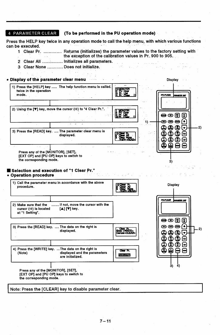
(To be performed in the PU operation mode)
Press the HELP key twice in any operation mode to call the help menu, . - with which various functions can be executed. 1 .
1 Clear Pr. .............. Returns (initializes) the parameter values to the factory setting with the exception of the calibration values in Pr..900 to 905.
2 Clear All ................ Initializes all parameters. .
3 Clear None ............ Does not initialize.
Display of the parameter clear menu - - - Display
1 - Press any of the [MONITOR], [SET], I - - [EXT OP] and [PU Opl keys to switch to the corresponding mode.
- - W Selection and execution of "1 Clear Pr."
Operation procedure
1) Call the parameter menu in accordance with the above p rocedu re.
....... If not, move the cursor with the cursor (e) is located at '1 Setting'.
[A] [VI key.
3) Press the [READ] key. .... The data on the right is displayed.
4) Press the [WRITE] key. ... The data on the right is (Note) displayed and the parameters
are initialized.
+ Press any of the [MONITOR], [SET], [EXT OP] and [PU Opl keys to switch to the corresponding mode.
Display
i) 4)
i Note: Press the [CLEAR] key to disable parameter clear.
7- 7 7

Selection and execution of "2 Clear All" Operating procedure 1) Call the parameter clear menu in accordance with page
7-1 1.
- Display
I
I I . .
- . b
2) Using the [VI key, move the cursor (9) to '2 Clear All'.
1
I I I
. 4
3) Press the [READ] key. .... The data on the right is ~
displayed.
I 4) Press the [WRITE] key. .. The data on the right is
(Note) displayed and the parameters a re initialized. I I
3) 4) 1
Press any of the [MONITOR], [SET], [EXT OP] and [PU OP] keys to,switch to the corresponding mode.
1
. . ~~
Note: Press the [CLEAR] key to disable clear All. . .
W " 3 Clear None"
When "3 Clear None" is selected, the parameters are not initialized.
.. . - - .
-- . / . %. -
. . _ . . . .
. , . - _ . I
7 -.I2

- _ Displays the history of eight past alarms.
Operation procedure . - 1) Press the [HELP] key ..... The help function menu is called. * Display
. . I . twice in the operation
I
mode. . - -
- .
- . -
2) Press the [SHIFT] key .... The screen moves to the next and [V) key together. page.
. . I
h 1 3) Make sure that the
cursor (9) is located at "5 Alarm Hist".
....... If not, move the cursor with the [A] [VI key.
P\ I 4) Press the [READ] key. .... The alarm history is displayed. I - - > .
I . - Press any of the [MONITOR], [SETJ, . - [EXT OP] and [PU OP] keys to switch to the corresponding mode.
. _- -
> _
Clears all the alarm history. - - . Operation procedure 1) Press the [HELP] key ...... The help function menu is called.
twice in the operation- mode.
-_
D i s PI ay
I _ _
2) Press the [SHIFTJ key ..... The screen moves to the next and ['I] key together. page.
e? 3) Using the [VI key, move the cursor (9) to
4) Press the [READ] key. .... The data on the right displayed.
5) Press the [WRITE] key. ... The data on the right is (Note) displayed and the alarm history
is cleared.
1 Press any of the [MONITOR], [SETJ, [EXT OP] and [PU OP] keys to switch to the corresponding mode. I
Note: Press the [CLEAR] key to disable Alarm History Clear.
7-13

Resets the inverter. If the protective function of the inverter is activated to-trip (protect) the inverter, the trip state can be reset by the following operation. The trip state can also be reset by switching the power off or connecting terminals RES-SD.
Operation procedure
1) Press the [HELP] key ..... The help function menu is called. twice in the operation mode.
I _ _ _ _ _ ~
2) Press the [SHIFT] key .... The screen moves to the next and [VI key together. page. r
I ~ ~~
3) Using the [VI key, move the cursor (4) to "7 Inv. Reset'.
I key. .... The data on the right is
displayed.
key. ... The inverter is reset and (Note) switches to the monitoring mode.
Display . .
I Note: By pressing the [CLEAR] key, the inverter is not reset and is switched to the monitoring mode.
. . _ _
. - .
. . - . . . . - _. . .
. , .- . . . - , . I "
. . .
7-14

If the inverter appears to operate incorrectly, perform the following operation to display the most likely cause of the fault. This operation may also be performed during inverter operation (PU operation, external operation) or during alarm trip (protect,ion activated).
- .. . - . . .
Operation procedure
1) Press the [HELP] key ..... The help function menu is called. twice in the operation . mode.
. Display .
I . -
I I J
i - -_
6) Press the [WRITE] key. ... The cause of fault is displayed. (See page-7-1 6.) - ?
I I
. . _ . I . '
- . . . \ . ..
. . . . - - . - - . .. - . . ,. , ._ . . .
. , . .,
. . .- .. . - ~ . . -_ . . . . - . ._- . . . .
7-15

Faults - 1 M-.NOT RUNNING (Motor does not rotate)
The inverter has alarm-tripped (pro- . tection activated), resulting in output shut-off. Press the [SHIFT] key to dis- play the cause of the trip.
The main circuit power of the inverter is lost, or open phase has occurred in the power supply. Check the power See Pr.70
~ supply.
Both start signals STF-and STR are ON or OFF.
output shut-off input terminal MRS Is ON MRS is ON.
The inverter starting frequency (Pr. .
13) set value is higher than-the cur- M.NOT RUNNING
PI Control ' rent set frequency.
b
Neither of the FWD and REV keys are ON in the PU operation mode.- . .~ I - ->
From PU
The inverter cannot be started be- cause the inverter starting frequency (Pr. 13) value is higher than the maxi- mum frequency (Pr. 1).
The inverter cannot be started be- cause the fonnrard or reverse rotation has been inhibited by the value set in Pr. 78.
The invefler cannot be started since the current limit function is operating. Press the [SHIFT] key to display the assumed cause of activating the current limit function. The inverter cannot be started be- cause it is the stop period in the pro- grammed operation mode: .. ' .
- - * t
The inverter is not started because the operation- of PI control has re- sulted in a condition under which the' inverter need not be started: ,
Restart cannot be made since the automatic restart after instantaneous power failure select=terminal CS is OFF. Currently it is assumed to be after an instantaneous power failure or in the commercial power supply switch-over operation mode.
t ~-
- 2 M.SPEED ERROR (Speed does not match the running fre- quency set value)
If the running frequency set value is higher than the maximum frequency (Pr. 1) set value, the running fre- quency remains at the maximum fre- quency. If the running frequency set value is lower than the minimum frequency (Pr. 2) set value, the running fre- quency has been risen to the mini- mum frequency.
within the frequency jump setting
quency has jumped.
The current limit function has been activated and forced the running fre- quency to reduce. Press the [SHIFT] key to display the cause of activating the current limit function.
caused the running frequency to be offset from the set value.
The operation of PI control has
- 3 M:A/Dec Err (Acceleration/deceleration time is longer than the value set in Pr. 7/Pr. 8)
-Acceleration time set value (Pr. 7) is displayed.
L F r e q u e n c y reached in the above set time (acceleration/deceleration refer- ence frequency, Pr. 20) is displayed.
Deceleration time set value (Pr. 8) is displayed.
Frequency from whlch deceleration is made in the above set time (accelera- t i o n/d ec e l e r at lo n refer en c e f r e- quency, Pr. 20) is displayed.
7 -,I6

7 i
> >
I
1 i
i >
I i: I
._ I 4 M.Curr.High (Inverter output current value is larger than normal)
- '
First, the running frequency, out- put current and output voltage of the inverter are displayed. Press the [SHIFT] key to display the as- sumed cause of large output cur- rent.
1 0 ~ P ~ V r
Is the motor a special motor other than the general-purpose 3-phase induction motor? If so, reduce the torque boost set value. Related parameters: Pr. 0, 38, 46
I I Low-Trn * el Is the motor a constant-toraue mo- tor (motor for inveiter)? If'so, re- duce the torque boost set value., Related parameters: Pr. 0, 38, 46
I L;'- v Since the torque boost set value may be inappropriate, check the following relevant parameters: Related parameters: Pr. 0, 38, 46
Since the V/F pattern setting may
lowing relevant parameters: Related parameters: P_r. 3 ,14 ,19 , - -
Q Q- Q 9 47
be inappropriate, check the fol-
The load may be too heavy. An open phase may have occurred between the inverter and motor.
Note: If the fault could'not be identified by the above operation If the cause of the fault could not be found in the inverter, the current runn- ing frequency, output current and out- put voltage are displayed on the screen.
-
. - I Press the [SHIFT] key to display-the - 'relevant assumed cause.- .
I I . . - _ , . ~ . - . . .
. . . _ ... . . " - - - - -
3.2.4 .. - .Other Help Function t .- Graphic function
Press the [HELP] key on the parameter setting screen to display the data of the corresponding parameter graphically.
Operation procedure (Example: Pr. 3 "starting frequency") Display
, played graphically. -
2
. ousscreen.
. - - -
. -
t
7-17

3.3 SElTlNG AND CHANGING THE VALUES IN THE PARAMETERS
The inverter has many parameters. Using the PU, the required parameters can' be selected and their values set and/or changed as appropriate according to the load and running conditions. For more information, see the "Parameter List" (page 9-1). 'To stop parameters being changed, set "1" in Pr. 77 "para meter write disable". (See page 9-37.)
Operation procedure (Reading and writing the value of Pr. '8 "deceleration- time") -
' Display
parameter setting mode. a.
........... The screen on the right is 1) p-l ' 1 L r '
3) 5 )
4) 6) - -
...... If an error is displayed by memory. pressing the [WRITE] key, see
page 4-3.
7) Press the [SHIFT] key to move to the next parameter (Pr. 9) and call the current set value. Then, press the [SHIFT] key to advance to the next - parameter. 9
Note 1: If a setting error has occurred during the entry of a set value, press the [CLEAR] key to return to the status before that set value was entered.
Note: Set and/or change the parameter values in the PU operation mode. When the PU operation display is not shown, switch to the PU operation mode in accordance with page 5-6. Note-that the values of the following parameters may be set and/or changed in the edernal
3-speed setting ............ 1 ....... Pr. 4 to 6 Multi-speed setting .............. Pr.'24 to 27
1 operation and combined operation modes: ~- Display function ................... Pr. 51 to 56 Calibration function ............. Pr. 900 to 905
- _ _ .
n addition to the above procedure, the help function may be used to call the parameter list for setting. For more information, see page 7-8.
- 8 - 1
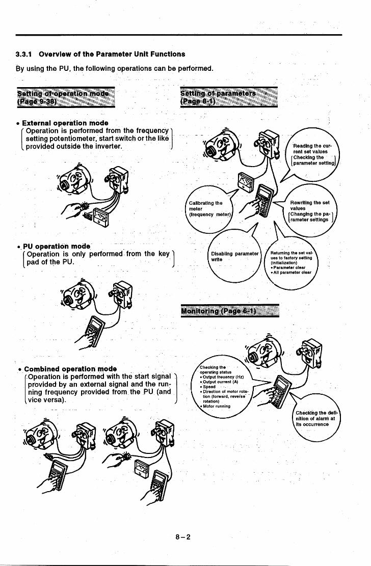
3.3.1 Overview of the Parameter Unit Functions
By using the PU, the following operations can be performed. _ -
4 _I
SettSng of ]parameters (Page 8-1)
Setting of operation mode (Page 9-38)< I
- - .
External operation mode
1 Operation is performed from the frequency setting potentiometer, start switch or the like provided outside the inverter.
- . _
- -. 0. PU operation mode'
1 Operation is only performed'from the key pad of the PU.
. . ..
- . . .
Combined operation mode
1 Operation is pefformed with the start signal provided by an external signal and the run- ning frequency provided from the PU (and I vice versa).
c.
of motor rota-
Checking the def nitlon of alarm at its occurrence u
8-2

3.4
3.4.1 Parameter List
Note 1: The set value depends on the inverter capacity: (7.5K and down)/(l-lK and up). 2: In the Screen Display section, f indicates a frequency, V voltage, I current, and t time.
.9- 1

(R E
.- w
r .c
.- $ - .- 5 a
. - - . F l c e t e r s * 781 setfor programmed operation. ' t .
9-2

. Name
0 to 1OV : 1 to 400Hz O.01Hz Oto20mA~Oto60Ht O.OIHz (4mA) OHz
005 Fraailanev sattina eiirrant anin Fxtlnnin
Note 3: Indicates the parameters which are ignored when the magnetic flux vector control mode is selected. *: When the FR-PUOlE is used, read and write of these parameters cannot be performed. (IF performed, Err is
* displayed.) (Set the calibration function numbers 900 to 905 using C-1 to C-6.) The parameters marked 4 have special functions. For more information, refer to the following list.
4:- The parameters hatched allow their set values to be changed during operation i f 0 (factory setting) has been set in Pr. 77 (parameter write disable). Note that the Pr. 72 setting cannot be changed in the external operation mode.
5: The functions of the FM and AM terminals change according to the set values of Pr. 54 (FM terminal function selection) and Pr. 158 (AM terminal function selection).
.
- 6: The factory setting for the FR-A241 (400V) series is 400V. - . -
7: When any of 12, 14 and 16 is selected, the input of the RT signal causes the inverter to shift to V/F control. (During
8: These parameters may only be set under the following conditions: Pr. 77 = 801 or 901, Pr. 80 # 9999, Pr. 81 # 9999
9: This parameter may also be set when 801 or 901 is set in Pr. 77. (The setting may alsobe changed during operation.)
The parameters. listed below are valid only when the corresponding parameters in-Remarks are set.
a stop only.)
(The settings can be changed during operation.)
- _ - (Cannot be cleared from the FR-PU02E.) - -
10: With 701 set in Pr. 77, this parameter can be set under the following conditions: Pr. 96 = 5 7 , Pr. 80 ?c 9999, Pr. 81
11: This parameter can be set and is valid when the inboard option FR-EPA, EPB or EPC is fitted and Pr. 105 # 9999. 12: This parameter can be set when Pr. 77 = 701. (0: standard feature, 5: with stop-on-contact control, without load
torque high-speed frequency control, 6: without stop-on-contact control, with load torque high-speed frequency control, 7: with stop-on-contact control, with load torque high-speed frequency control)
13: With 701 set in Pr. 77, these parameters can be set when Pr. 96 = 6 or 7. (The settings may also be changed during operation.) At this time, multi-speeds f (speeds 4 to 7) are valid. (Multi-speed operation'can be performed.)
14: This parameter can be set and is valid when Pr. 60 = 7, the FR-EPA, EPB or EPC inboard option is,fitted, and Pr. 105 f: 9999.
15: With 701 set in Pr. 77, this parameter can be set when Pr. 96 = 5 or 7.
# 9999 (The setting may also be changed during operation.)
9-3

Pr. 0 - Pr. 1
Factory Setting Model
3.4.2 Setting of Parameters to Improve the Corresponding Operational Functions
Setting Range
To kiepgespeed than*&Tsd ' trsquenqfof the machine ~
7.5K and below 11 K and above
< - a
Oto30% I 6 % 3 %
- w
I . output Base frequency (Hz) frequency
- _
Factory Setting 120 Hz
0 Pr. 0 "torque boost (manual)"
Used to adjust the motor voltage during low-frequency opera- tion, thereby increasing the motor torque at the time of start.
Setting Ranqe 0 to 120 Hz
Factory Setting 120 Hz
Setting Ranqe 120 to 400 Hz
Note: 1. This parameter is ignored when Pr. 80 and Pr. 81 have been set to select the mag- netic flux vector control mode.
motor (constant-torque motor) is used, change the setting of this parameter as follows:
2. When the inverter-dedicated
7.5 K and down ... 4 % 11 K and up ... 2 %
Pr. 1 "maximum frequency" or Pr. 18 "high-speed maximum frequency"
Allows the upper limit of the output frequency to be clamped. 0 The maximum setting is within
120 Hz. Use parameter Pr. 1 "maximum frequency" to set the upper limit of the output frequency.
The maximum setting is higher than 120 Hz. Use parameter Pr. 18 "highspeed maximum frequency" to set the upper limit of the output fre- quency. Setting this parameter automatically changes Pr. 1 "maximum frequency! to this set- ting.
9-4
Frequency 5 v setting signal (1OV)
(20 mA)
x # I E
U a
?!
n
.c
c
d
Frequency 5 v setting signal (1OV)
(20 n.4

Pr. 2-Pr.3
Factory Settinq Setting Ranqe 0 Hz 0 to 120 Hz
t
To run the motor as soon-as*the start signal is .switched on, without setting the frequency
'
J Pushbutton
0 Pr. 3 "base frequency", Pr. 19 "base frequency voltage"
Allows the base frequency (reference frequency at the rated motor torque) to be set as appropriate between 0 and 400Hz according to the motor rating.
dote: 1. Set the base frequency to 60Hz for use of an inverter- dedicated motor (constant- toque motor).
2. When the magnetic flux vector control mode has been se- lected in Pr. 80 and Pr. 81, Pr. 19 is regarded as about 200V (or 400V).
in Pr. 19 makes the maximum output voltage identical to the power supply voltage. Setting "8888a in Pr. 19, the maximum is output voltage 95% of the power supply voltage.
3. Setting "9999' (factory setting)
9-5
se frequency setting range 4
voltage Base fre-

Pr. 4- Pr. 6
. *
0 Pr. 4 "3-speed setting (high speed)", Pr. 5 "3-speed setting. (middle speed)", Pr. 6 "3-speed setting (low speed)", Pr. 24 "multi-speed setting (speed 4)", Pr. 25- "multi-speed setting (speed 5)", Pr. 26 "multi-speed setting (speed 6)", Pr. 27 "multi-speed setting (speed 7)"
Allows any speed to .be selected by switching the external contact signal (across terminals RH/RM/RL and SD).
Each speed (frequency) may be specified as appropriate bet- ween 0 and 400Hz during inverter operation. The speed may also be set using the [A] and [VI keys. (On releasing the [A] and [VI keys, the set frequency is stored, that is the [WRITE] key need not be pressed.)
By using these functions with jog frequency (Pr. 15), maximum frequency (Pr. 1) and minimum frequency (Pr. 2), up to 10 speeds can be set.
output
(H4 . frequency
Time
Across RH-SD
Across RM-SD
-Across RL-SD
Note: 1. Speeds 4 to 7 are not selected if the setting is '9999' (factory
2. These speeds have priority over the main speed (across terminals . 2 and 5,4 and 5).
3. This setting may be made during PU operation or external opera- tion.
4. With 3-speed setting, if two or three speeds are simultaneously selected, priority is given to the frequency of lower signal.
- setting).
9-6

Pr. 7
Model 7.5K and below 11K and above
3 Pr. 7 "acceleration time", Pr. 20 "acceleration/decelera- tion reference frequency", Pr. 21 "acceleration/decelera- tion time increments".,
Factory Setting Setting Range 5 seconds 15 seconds
0 to 3600 seconds / 0 to 360 seconds 0 to 3600 seconds / 0 to 360 seconds
(1) Confirmation of acceleration time setting range and minimum setting increments Use Pr. 21 "acceleration/deceleration time increments" to set the acceleration time setting range and minimum set- ting increments. Before setting the acceleration time, the set value must be checked. Set value "0" ........................ 0 to 3600 seconds (factory setting) - (minimum setting
increments: 0.1 seconds) Set value "1 I' ......................... 0 to 360 seconds
(minimum setting increments: 0.01 seconds)
(2) Setting of acceleration time In acceleration time (Pr. 7), set a period of time required to reach the acceleratiodde- celeration reference frequen- ,9:;,"F;cy cy (Pr. 20) from OHz. Set a longer time to accelerate more slowly, and a shorter
rapidly. (Note)
r"!
time to accelerate more Acceleration
Note: 1. In only S-pattern acceleratiorddeceleration A (see page 9-16), the set time is a period of time required to reach the base frequency (Pr. 3).
-2. If Pr. 20 (acceleration/deceleration reference frequency) setting is changed, the set values of calibration Pr. 903 and Pr. 905 (frequency setting signal gain) remain unchanged. To adjust the gains, adjust calibration Pr. 903 and Pr. 905.
3. When thesset value of Pr. 7 is "O', the acceleration time is set to 0.04 seconds. At this time, set 120Hz or less in Pr. 20 'acceleratiorddeceleration reference frequency '.
9-7

Pr. 8-Pr. 9
.
n
Model Factory Setting Setting Range 7.5K and below 5 seconds 11 K and above 15 seconds
0 to 3600 seconds / 0 to 360 seconds 0 to 3600 seconds / 0 to 360 seconds
W
, Y . -.
n
Note: When two or more motors are run simultaneously, provide a thermal relay for each motor.
0 Pr. 8 "deceleration time", Pr. 20 "acceleration/decelera- tion reference frequency", Pr. 21 "acceleration/decelera- tion time increments"
(1) Confirmation of deceleration time setting range and minimum setting increments Use Pr. 21 "acceleration/deceleration time increments" to set the deceleration time setting range and minimum setting increments. Before setting the deceleration time, the set value must be checked. Set value "0" ....................... 0 to 3600 seconds (factory setting) (minimum setting
increments: 0.1 seconds) Set value V " ......................... 0 to 360 seconds (minimum
setting increments: 0.01 seconds)
(2) Setting of deceleration time In deceleration time (Pr; 8), set a period of time required to reach OHz from the accel- eration/deceleration refer- ence frequency (Pr. 20). Set frequency
a longer time to decelerate more slowly, and a shorter time to decelerate more rap-
- - - -
,
' & idly. (Note)
INote: When the set value of Pr. 8 is "O', the deceleration time is set to 0.04 I

Pr. 10 - Pr. 13
Parameter Pr.10 Pr.11
. .
. .
. ,
Factory Setting Settinq Range 3Hz 0.5 seconds
0 to 120Hz,9999 (Note 1) 0 to 10 seconds, 8888 (Note 2)
. . . . . .
1.... .
. . . .
0 to 30% 7.5K and below ... 6%,
Pt. 10 "DC dynamic brake operation frequency", Pr. 11 0 "DC dynamic brake operation time", Pr. 12 "DC dynamic
brake voltage" Setting the stopping DC dynamic brake voltage (torque), operation time and operation starting fre- quency al lows the stopping accuracy of positioning opera- tion, etc. to be adjusted accord- ing to the load.
c 3 0
e n c c
ration G
Operation Time <When load is large> Set a short time in Pr. 11 "DC dynamic brake operation time". Set a large value in Pr. 12 "DC dynamic brake voltage". <When load is small> Set a long time in Pr. 11 "DC dynamic brake operation time". Set a small value in Pr. 12 "DC dynamic brake voltage".
Note: 1. Setting 9999 in Pr. 10 allows the DC dynamic brake to start at the frequency set in Pr. 13 (starting frequency).
2. When 8888 is set in Pr. 11, connection of terminal MRS-SD starts the DC dynamic brake. At this time, the essential function (output stop) of terminal MRS is invalid.
3. When an inverter-dedicated motor (constant-torque motor) is used, change the setting of Pr. 12 "DC dynamic brake operation frequency" as described below:
7.5K and below ..... 4%, 1 1 K and above ..... 2%
I A CAUTION I A D O not set 8888 in Pr. 11.
A Install a mechanical brake. The motor may not stop correctly during orientation.
There is no holding torque at stop.
0 Pr. 13 "starting frequency"
Allows the starting frequency to be set between 0 and 60Hz. For example, when the starting frequency setting is 5Hz, the sett
motor starts running as soon as Ran
the frequency setting signal reaches 5Hz. Also, when the setting is higher : signal 01)
than 5Hz, entering the start sig- or ward ON
t
nal causes the frequency output to start from 5Hz.
rotation
s9-9

Pr. 14
Set Value
.
5
? I >
ON (Note) OFF For lift No boost for reverse rotation
For lift No boost for forward rotation (Prl4=3)
For constant-torque loads (Pr. 14=0) , (Prl4=2)
For constant-torque loads (Pr. 14=0)
i
1
i
t3 Pr. 14 "applied load selection"
Conveyor, carrier, etc. (for constant-torque loads) Set "0" (factory setting).
. . . . equency
2)
Fan and pump (for variable-torque loads) Set "1 ". The inverter accelerates slowly until the motor starts running to prevent the inverter from being
Since an overvoltage is more likely to occur in this load characteristic than in the constant-torque load characteristic, set a longer deceleration time.
stopped by the overcurrent pro- tection function. Output Frequency(Hz)
Base Frequency
Note: When the RT terminal signal is on, the second control functions (second acceleration/deceleration time, sec- ond torque boost, second base frequency) are selected. When the magnetic flux vector control mode has been selected in Pr. 80 and Pr. 81 , the setting of this parame- ter is ignored.
9-10

Pr. 15 - Pr. 16
OS seconds
Pr. 15 ''jog frequency", Pr. 16 "jog acceleration/decelera- ti o n ti me 'I, P r . 2 0 I' a cce I e ra t i o n/dec e I e ration ref e re n ce frequency", Pr. 21 "acceleration/deceleration time incre-
0 to 3600 seconds/ 0 to 360 seconds
me n t s " Allows jog operation to be started and stopped by selecting the jog'mode (connecting terminals JOG and SD) and turning on/off the start signal (terminals STF,STR). Jog operation may also be performed by using the parameter unit. For full information on the operation procedure, see page 5-1 1.
Setting of frequency and accelerationldeceleration time
(1) Confirmation of acceleration/deceleration time set-
Factory Setting 5HZ
< - -
Setting Ranqe 0 to 400Hz
-. 1 . - - .
I . .
. - . .
. ,
. - , ting range and minimum setting increments
Use Pr. 2 1 "acceleration/deceleration time increments" to set the acceleration/deceleration time setting range and minimum setting increments. Before setting the accelera-
Set value "0" . tioddeceleration time, the set value must be checked.
................... $77 0 to 3600 seconds
0.1 seconds)
(minimum setting increments: 0.01 seconds)
(factory setting). (minimum setting increments: - Set value "1 'I.. .................. 0 to 360 seconds
(2) Setting of acceleration/deceleration time . In Pr. 16 "jog acceleration/deceleration time", set accel- eration/deceleration time for jog operation. Acceleration time is a period of time required to reach the acceleration /deceleration reference frequency (Pr. 20) from OHz.
output Frequency (Hz)
Deceleration time is a pe-
reach OHz from the accel- eration/deceleration refer- ence frequency (Pr. 20). Jog
' Set a longer time to accel- 'requ
erate or decelerate more slowly, and a shorter time
ate more rapidly."
riod of time required to
- to accelerate or deceler- Acrossx)Q-
. (Note 1, 2) J ' STR-SD
Factory Setting I Setting Range
. . . .
Note: 1. In S-pattern acceleration/deceleration A (see page 9-1 6), the set time is a period of time required to reach the base frequency (Pr. 3).
2. If Pr. 20 (acceleration/deceleration reference frequency) setting is changed, the set values of calibration Pr. 903 and Pr. 905 (frequency setting signal gain) remain unchanged. To adjust the gains, adjust calibration Pr. 903 and Pr. 905.
(3) Setting of frequency In Pr. 15 (jog frequency), set the running frequency for jog operat ion.
9-11

Pr. 17
9 Pr. 17 "external thermal relay input" -
Change the set value to 111" or "3" to switch the function of the _ _
input ierminal JOG/OH from the factory setting of the jog mode to OH (external thermal relay input). OH is used to input the signal contact of .a thermal relay installed outside the inverter or that of a temperature sensor built in the motor. Change the set value to "2" or "3" to switch the function of the MRS terminal to N/C contact input specification (normally closed input). Also, when any of 4 to 7 is set in this parameter, the output terminal to which "9" was set in Pr. 40 (output terminal assign-
- - External thermal relay
ment) acts as the zero current detection signal terminal. Temperature
JOWOH Terminal Function Function MRS Output Terminal
Signal to Which N/O N/C "9" Was Set in r OH
mode input input Pr. 40 (external thermal relay input)
Pr. 17 Set Value
- 0
setting) 1
(factory -e I During PU<
- - a - operation
. .
Open motor circuit detection For details, refer to page 9-40. I
-1 piTiiKi1 (factory setting)
Thermal rday Thermal relay
3 SD GB SD
output Stop ?.& output stop
J
p\ CAUTION
A With the external thermal relay connected, do not switch to jog operation. The motor will start with the start signal only.
9-12

Pr. 18 - Pr. 19
~~
Factory Setting 120Hz
n 150Hz ~
Setting Ranqe 120 to 400Hz
Special motor
9999
0 Pr. 18 "high-speed maximum frequency"
This inverter is factory-set to the maximum running frequency of 120Hz. To run at the frequency over 120Hz, set a value of
. grater than 120Hz in Pr. 18 "high-speed maximum frequency". Pr. 1 "maximum frequency" is automatically changed to this set value.
0 to lOOOV, -
8888,9999
0 Pr. 19 "base frequency voltage"
By setting 200V in Pr. '1 9 "base frequency voltage", a motor of rated voltage lower than the power supply voltage to the in- verter can be used. Factory Settinq I Settinq Ranqe
Note: 1. Setting "9999" (factory setting) in Pr. 19 makes the maximum output voltage identical to the power supply voltage.
2. When the magnetic flux vector control mode has been selected in Pr. 80 and Pr. 81, Pr. 19 is regarded as about 200V (or 400V).
3. By setting "8888" in Pr. 19, the maximum output voltage is 95% of the power supply voltage. (Set "8888" in Pr. 19 when using a special motor of other than a Japanese manufacturer, for example.)
<Pr. 20, Pr. 21 0 See the section of Pr. 7> -
I -
f"')
9- 13

Pr. 22 - Pr. 23
Pr. 22 l%tall prevention operation level" c3 Pr. 23 "stall prevention operation level at double speed"
Pr. 66 "stall prevention operation level reduction starting frequency"
In Pr. 22 "stall prevention opera- 1~r221 tion level", set the stall preven- kg tion (current limit) operation level. .z $ Normally set to 150% (factory set- 5 S
L .- ting). zi
400"z Output frequency Note: The set value (%) indicates a
- _
ratio of the current value to the rated output current of the
When operation is performed at high speed at or over 60Hz, acceleration may not be possible because the motor current does not increase.
When operation is performed in the
To improve the operation character- istic of the motor in such a case, the
high-frequency range, the current in
than the rated output current of the inverter and the inverter does not result in an alarm (protective func- tion not activated). Pr. 66 is the reduction starting frequency, and Pr. 23 the reduc- tion ratio correction coefficient.
By setting "9999" (factory setting) in Pr. 23, the stall prevention (current limit) level is kept constant at the Pr. 22 set value up to 400Hz. Calculation expression for current limit operation level Cu rrent I imi t ope rat ion
level (%)= A + B x
Setting example (Pr.2245096, Pr.23=100%, Pr.6640Hz)
current limit level- in the high- ~2 frequency range can be reduced. ;: .... &.-
,% I- _ _ - - - - ._ _. ._
gg
0 60 100 200 300 400 the locked motor state is smaller Output frequency
-
- >
? - , r
output frequency (Hz) where, A =
When "0" is set in Pr. 22, the stall prevention operation is not performed.
When "9999" is set in Pr. 22, the stall prevention level can be changed bylerminal No. 1. A specific method is given below.
A CAUTION
, .
.
A Do not set a too small value as the stall prevention operation current. Torque generated will reduce.
9 0-14

Pr. 23 - Pr. 27
Set "9999" in Pr. 22 to change the-stall prevention operation level according to the voltage applied to terminal 1. (The fast- response current limit level remains unchanged.)
Set "9999" in Pr. 22 "stall prevention operation level".
-
Setting method
Stall prevention operation level signal
Enter 0 to 5V (or 0 to 1OV) into terminal 1. (Setting ."9999" in Pr. 22 automatically switches the function of the auxiliary input terminal to a stall prevention operation level signal input.)
+
Functions
A Fast-response c current limit level
Current limit level at input voltage of 10V/5V Set in Pr. 149.
t * (5/10VDC)
Note: 1. Set 701 in pr. 77 to enable read and write. (When Pr. 77 = 701, Pr. 22 acts as a parameter for fast-response current limit level.)
2. Use Pr. 73 to switch the terminal 1 input voltage between 0 to 5V and 0 to IOV.
3. When 9999 is set in Pr. 22, the terminal 1 input is dedicated to stall prevention level setting. Therefore, the auxiliary input and override functions of terminal 1
-are made invalid. 4. The setting of this parameter is ignored when the
magnetic flux vector control mode has been selected using Pr. 80 and Pr. 81.
5. The fast-response current limit level is factory-set to 170%.
<Pr. 24, Pr. 25, Pr. 26, Pr. 27 c=) See the sectio-n of Pr. 4s
9-15

Pr. 28 - Pr. 29
c=) Pr. 28 "multi-speed input compensation" By entering a compensation signal into the auxiliary input termi- nal 1 (Note), the speeds (frequencies) of multi-speed settings -selected by the RH, RM and RL terminals can be compensated for.
input 1 -
J
Compensation (Note) When any of 4,5,14 and 15
compensation signal is entered into terminal 2.
Set value b Auxilia In ut is set in Pr. 73, the
Compensation available
0 P r . -29 I' acce I e rat i o nld ece I e rat i on pattern 'I General application p s z G i a ] set n o n (factory setting). A general [Linear accelerationldecelerationl
accele rat ion/deceIe rat io n pattern (linear acceleration/deceleration) L. is achieved. =I- Generally this setting is used for 5 t
fm
E N
operat ion. 6. Time
For machine tool spindles Set "I". This setting is used when it is necessary to make accelera- tion/deceleration in a short time up to the 60Hz or higher speed range (S-pattern acceleration/decelera- tion A). In this acceleration/decel- eration pattern, fb (base frequency) is always the inflection point of an S shape, allowing acceleration/de- celeration time to be set according to the reduction in motor torque in the 60Hz or higher constant-output operation range (Pr. 7, Pr. 8).
Note: For the acceleration/deceleration time, set the time re- quired to reach the base frequency (Pr. 3), not the accel- eration/deceleration reference frequency (Pr. 20).
0 Prevention of cargo collapse on conveyor, etc. -1
celeration/deceleration from f2 (current frequency) to f l (target frequency), easing acceleration/
has an effect on the prevention of cargo collapse, etc.
Set "211 to provide an S-pattern ac- [Spattern accelerationldeceleration 61
, deceleration shock. This pattern t
9-16

Pr. 29 - Pr. 36
Backlash compensation for reduction gear, etc. Set "3". This function stops the output frequency change tem- porarily during acceleration/deceleration, reducing shock (back- lash) generated when a reduction gear backlash is eliminated suddenly. Use Pr. 33 to 36 for the setting.
- ..
w <Pr. 30 0 See page-22-2>
Pr. Number Functlon Name p::: Backlash
frequency Backlash 0 to 0.5 seconds 34 ~~~.~~e 360 seconds (9999)
frequency
Backlash 0 to 0.5 seconds 36 ,",xc"6"!","B 360 seconds (9999)
Note: Pr. 31 and 32 only are implemented as frequency jump I function. I A I I
Pr. 31 "frequency jump lA", Pr. 32 "frequency jump 1B" 0 Pr. 33 "frequency jump 2A", Pr. 34 "frequency jump 28"
Pr. 35 "frequency jump 3A", Pr. 36 "frequency jump 3B"
Allows a mechanical'resonant point to be jumped. Up to three areas may be set, with the jump frequency top and bottom point set for each area. The value set to 1 A, 2A or 3A is a jump point and operation is performed at this frequency.
1 Jump (frequency avoidance) area . I
. _ . -
The running frequency command within the set area is the running frequency atthe point marked 0.
D
Frequency setting signal
~~~
Note: 1. Frequency jump is not made when the set value is "9999" (factory setting).
2. Setting "3" in Pr. 29 switches Pr. 33 to 36 into the backlash compensation setting functions. But Pr. 33 to 36 setting ranges are not displayed on the PU screen. And the set values of the frequency jump parameters are displayed in the parameter change list and initial vatue list, that is, when Pr. 29 is set to 3, the set values of Pr. 33 to 36 are not displayed in the lists. (Pr. 31 and 32 are valid as frequency jump functions.)
3. During acceleration/deceleration, the running fre- quency within the set area is valid.
9-17

Pr. 37
Pr. 37 Set Value
2 to 10
.
11 to 9998
i i
Running Speed Display The set value is the number of motor poles.
0 The displayed value is the motor speed. Example: When the set value is "2'. 3600 (rimin) is displayed at
the output of 60Hz. Set the machine speed at 60Hz operation. Example: When the set value is 150 (rdmin), 150 (without
display unit) is displayed at the output of 60Hz.
i
.
. .
Pr. 37 "speed display" 0 Pr. 51 "inverter LED display data selection"
Pr. 52 "PU main display data selection"
Note: 1. Only the display unit is set in' this parameter. For the other frequency-related parameters (such as Pr. l), set a frequency unit.
2. In the V/F control mode, the motor-speed is converted into the output frequency and does not match the actual speed. When the
- magnetic flux vector control mode has been selected in Pr. 80 and 81, this display shows the actual speed (estimated value resulting from the compensation of motor slip). .
3. The factory setting is "4n (poles) (1800 r/min is displayed at the output of 60Hz).
.
., .
Pr. 53 "PU level display data selection"
I
z I
>
i I
c monitor) screen.
(3) Move the cursor (0) to "6 rpm" and press the [READ] key to call the speed monitor screen (unit: r/min).
. (4) Then press the [WRITE] key to define the speed monitor screen as the first priority screen.
1 I n L
.
I . ._ .
I A CAUTION I . A Always set the number of motor poles in Pr. 37.
Otherwise, th,e motor may run at overspeed, damaging the machine.
t I
9 -.18

Pr. 38 - Pr. 40
Pr. 38
Pr. 39
Automatically controls the inverter output voltage (torque) ac- cording to the load current detected.
Set the boost compensation value (%). Set "0' to disable the automatic torque boost. Normally set "100'(%) to operate the automatic torque boost. Set the automatic torque boost starting current (A). Normally set "O'(A).
0% .
, QA
' Set Value
set (Functionl Function Name I Palue Code Operation Related Pr.
Note: When the magnetic flux vector control mode has been selected in Pr. 80 and 81, the setting of the automatic torque boost is ignored.
_ - _ _ I
0 RUN Inverter running
SU Up-to-frequency li
0 Pr. 40 "output terminal assignment"
Output during operation when the inverter output frequency reaches or exceeds the starting frequency. Output when the output frequency reaches f10% of the set frequency. (Note 4) (Note 5)
-
Pr. 41
Any of 9 functions can be reassigned to the SU, IPF, OL and FU output terminals individually. Set a 4-digit integer in Pr. 40.
' The value in each digit indicates the function of the correspond- ing terminal.
Pr. 40 :- m-1 4th di it
IPF t L-p FU
OL t t su
Factory setting ....... "1234" . Terminal SU : SU (up-to-frequency) signal
Terminal IPF : IPF/UVT (instantaneous power failure or un- de rvo I t a g e) signa I
Terminal OL : OL (overload alarm) signal Terminal FU : FUI (frequency detection) signal
6 -
Output while the current limit function is ope rating . Output when the output frequency reaches or exceeds the specified detection frequencv. (Note 4) Output when the output frequency reaches or exceeds the specified detection frequency. (Note 4) Output when the electronic overcurrent protection cumulative value reaches 85% of the set level. Output in the program mode. (Note 6)
selected. (Note 8) Output when the PU operation mode is
Pr. 22, 23
Pr. 42, 43
Pr. 50
Pr. 9
Pr. 79
- Program mode PU operation mode
* PRG
Instantaneous power failure or undervoltaae
Overload alarm
Frequency detection
Output when instantaneous power failure or undervoltage occurs. I -
9- 19

Pr. 40 - Pr. 41
Note: 1. "0" set in the first digit of the four digits is not displayed. However, "0' set only in one digit is displayed.
2. The function of terminal RUN (output during inverter running) is fixed. This function cannot be changed by using Pr. 40.
3. "Output" indicates that the built-in transistor for open collec- tor output is turned on (conducts).
4. In the PLG feedback control mode, the operations of up-to- frequency (SU) and frequency detection (FU1, FU2) are as described below: , ,
- : SU, FU1 : Output when the actual speed (frequency) under the control of the PLG feedback signal reaches or exceeds the specified detection frequency.
: Output when the inverter output frequency reaches or exceeds the specified detection frequency.
5. When the frequency setting is changed by the analog signal or the [A]/[V] key of the PU, the output of the SU (up to frequency) signal may alternate between ON and OFF depending on the speed of that change and the timing of the changing speed determined by the setting of the acceleration/deceleration time. (Such alternation does not take place when the accel- eration/deceleration time setting is "0 seconds".)
6. Output when the inverter is switched to the external operation mode (goes into the programmed mode), with "5" set in Pr. 79 "operation mode".
7. 6 cannot be set. ._ 8. By setting "9" in this parameter, the function of the output
terminal changes to a zero current detection signal when any of 4 to 7 has been set in Pr. 17 (external thermal relay input).
*
,
FU2, '
.
~
~3 Pr. 41 "up-to-frequency sensitivity"
Allows the output signal ON range to be adjusted between 0 and f 100% of the running frequ- ency when the output frequency reaches the running frequency.
Adjustable range
Output signal
Low: Output transistor ON, HI&: Output transistor OFF
9-20

Pr. 42 - Pr. 43
Pr. 42 "output frequency detection", Pr. 43 "output frequency detection at reverse rotation" u -
Electromagnetic 0' brake control signal
I
. - - -
The signal across terminals FU and SE is switched low when the
. output frequency reaches or ex- ceeds the selected detection fre- - quency (value setin "output fre- quency detection", Pr. 42), and is switched high when it drops below the detection frequency. This function can be used for
,- electromagnetic brake opera- tion, open and other signals. Setting a value in Pr. 43 "output frequency detection at reverse rotation" allows the frequency to be detected exclusively for the reverse rotation, (In this case, the set value in Pr. 42 is for the forward rotation only.) This func- tion is effective for switching the timing of electromagnetic brake operation between forward rota- tion (rise) and reverse rotation (fall) during elevating operation. This parameter is factory-set to "9999". In this state, the detec- tion frequency is the Pr. 42 set value for both the forward rota- tion and reverse rotation.
\ .
-
6
Low: Output transistor ON, High: Output transistor OFF
Note:When the inboard option unit is used to exercise PLG feedback control, use the RUN (running) signal for brake release. (If the FU (output frequency detection) signal is used, the brake may not be released.)
9 -21

Pr. 44 - Pr. 49
Set Function I Parameter number
0
Signal across Terminals RT-SD
Pr. 44 "second acceleration/deceleration time", Pr. 45 "second deceleration time" Pr. 46 "second torque boost", Pr. 47 "second V/F (base frequency)''
The external contact signal (across terminals RT-SD) allows the acceleration and'deceleration times, boost setting, etc. to be changed together. . Effective for switching between two motors with different para- meter setting, e.g. elevating and traversing.
0
-
Pr. 7 Pr. 44 Pr. a Pr. 45 Pr. 0 Pr. 4 6 Pr. 3 Pr. 4 7
Acceleration time
Deceleration time
Torque boost (manual)
Base frequency '
0
0
' 0
0
0
0
0
0
Note: 1. Setting "9999" (factory setting) in Pr. 45 causes both the second acceleration time and deceleration time to be the value set in Pr. 44.
2, -When the magnetic flux vector control mode has been selected in Pr. 80 and Pr. 81, the setting of Pr. 46 is ignored. i
1 3. The second acceleration/deceleration time is the time -taken for acceleration to the frequency set in Pr. 20 "acceleration/deceleration reference frequency", as in Pr. 7 "acceleration time" and Pr. 8 "deceleration time".
-
Pr. 48 "second stall prevention operation current" c3 Pr. 49 "second stall prevention operation frequency"
Allows the stall prevention (current ' limit) operation level to be changed g
frequency set in Pr. 49. The setting : E of a IOW value is effective for a stop 5
* on contact,-which requires low >
This function is not-valid during ac- - -celeration and- is only valid during
deceleration or at constant speed. 0 This function is invalid when "0" is set in Pr. 49 (factory setting).
Note:- 1. The set value (%) indicates a ratio of the current value to the rated output.current of the inverter.
2. To make a stop upon contact on a higher level, refer to page 19-1.
I within the range from OHz to the h (9 - .__ ~ - - __ -
- - _ ~
, - torque at low speed. -
- -
- - .
L
. _
. . . . , . - I A Do not set a too small value to the second stall preven- tion operation current. The torque generated will reduce.
9-22

Pr. 50 - Pr. 54
0
0 Pr. 50 "second output frequency detection" .
c In addition to the detected output frequencies set in Pr. 42 and Pr. 43, another detected output frequency can be set. By setting "5" (FU2) in any of the first to fourth digits of Pr. 40, the signal-can be output from any of the SU, IPF, OL and FU terminals. The terminal signal is turned on at or above the set frequency (the built-in transistor is switched on). (See the section of Pr. 42 and Pr.-43.)
Pr. 51 "inverter LED display data selection" Pr. 52 "PO main display data selection"
. Pr. 53 "PU level display data selection" . - Pr. 54 "FM terminal function selection"
Pr. 158 "AM terminal function selection" - _
By setting any of the numbers in the following table, the required signal can be selected from among the 21 signals for the monitor and output signals. There are two types of signal outputs: FM pulse train output
I " terminal and AM analog output terminal. Different signals can be output at the same time. Select the signals using Pr. 54 and Pr. 158.
i") ,--
J <Factory setting> + - Pr. 51 ..." l", Pr. 52 ..." O", Pr. 53 ..." l", Pr. 54 ..." l",
FM A Pr. 158 ..." 9999"
. : .* _ . I - *
* * *
X 22 X X X X - 23 X X X X -
Orientation status Actual oDeration time Motor load factor
-
hr
% x 24 X X X Rated load of applied motor x2
i _ _ .
9-23

Pr. 51 - Pr. 54
Pr. 158 Set Value
Note: 1.Monitor cannot-be selected for items marked x. 2.Setting "0" in Pr. 52 "PU main monitor" allows the monitoring
of "output frequency to alarm display" to be selected in sequence by the SHIFT key. (Factory setting)
3.The load meter is displayed in %, with the current set in Pr.
4." "Frequency set value to output terminal status" on the PU main monitor are selected by "other monitor selection" of PU ope rat ion.
5."" "Motor torque" display is valid only in the magnetic flux
6.When any of the signals marked * has been selected in Pr. 54 "FM terminal function selection", the outputs of the FM and AM terminals are zero while the inverter is at stop or alarm.
7.Setting-"lI 2, 5, 6, 1 1, 17 or 18" in Pr. 53 or Pr. 54 allows the full-scale value to be set in Pr. 55 or Pr. 56.
8.The cumulative energization time is calculated from 0 to 65535 hr, is then cleared, and is recalculated from 0.
9.By setting "0" in Pr. 53, the level meter display of the PU can be switched off.
10.For the actual operation time, the length of time when the inverter is running is calculated. (The time when the inverter
' is at a stop is not calculated.)
- . 11.When the fast-response current limit function is activated, the outputs of terminals FM and AM are zeroed. (To prevent this, make the fast-response current limit function invalid or use the extension analog output of the FR-EPA or EPE option.)
12.The orientation status functions properly when the FR-EPA option is used. If the option is not used, "22" may be set in Pr. 52 but the orientation status does not function and "0" is d i s p I aye d.
-56 regarded as 100%. . -
-- ' vector control mode.
-_ -
Remarks Pr. 54 FM, AM Terminal Set Value Output Status
. I - 1
Use Pr. 54 and Pr. 158 to select the function of the AM terminal - in accordance with the following table:
9999 (factory setting)
1 to 21 Both the FM and AM terminals output the signal set in Pr. 54.
900 value may only be read and written. The calibration Pr. 901 value may only 101 to 121
I I lThe calibration Pr. I
1 to21
be read and written.
outputs the signal set Both the calibration in Pr. 54. Pr. 900 and Pr. 901
values can be read outputs the signal set and written. in Pr. 158.
, 1 to 21. . The FM terminal
101 to 121 The AM terminal
: When any of "1 to 21" has been set in Pr. 158, setting either any of "1 to 21" or any of "101 to 121" in Pr. 54 causes the same signal to be output from the FM terminal.
<Setting examp le> To output the output frequency from the FM terminal and the output current from the AM terminal 0 Set 1 in Pr. 54 (adjust the full-scale value in Pr. 55).
Set 2 in Pr. 158 (adjust the full-scale value in Pr. 56). For adjustment, see pages 11 -1 to 11 -3.
- 9-24

Pr. 55 - Pr. 56
Pr. 55 "frequency monitoring reference" Pr. 56 "current monitoring reference" 0
Set the frequency or current which is referenced for display
-when the frequency or current is selected for the FM and AM ter-
- minals and PU level meter dis- play -
1440Hz (terminal FM) lOVDC (terminal AM) Full $40 (PU levd monitor) r,
Yonltorlng ",:c% Level FM, AM Termlnal -- S e t W (Setting Setting !F:; Functlon Pr. 54 Setting Selection
t setting Running speed 1 , . 1 101
monitoring 5 105 5
' output f (Hz) fsating - reference ,(W
Pr. 55 Running speed 6 6 106 (Pr. 97)
2 102 output1 (A)
,1 11 111 Peak1 konitoring (A)
17 117 reference Load pr. 58 ,meter l7
Motor exciting1 18 18 118 (A)
f
-
1440Hz (terminal FM) IOVDC (terminal AM) Full scale (PU level monitor) r,
output or asplay v] Output current Peak I Load meter Motor ex. I
Note: 1. FM maximum output f is 2400Hz. Hence, adjust Pr. 55. If Pr. 55 is not adjusted, the output of terminal FM will be stabilized.
2. AM maximum output voltage is IOVDC.
.9 - 25

Pr. 57 - Pr. 58
,9999 (factory setting) 0 , l to 5 seconds
$7
Disable Enable
Pr. 57 "coasting time for automatic restart after instantaneous power failure/commercial power supply-
0 inverter switch-over': Pr. 58 "rise time for automatic restart after i n st a n t a n eo us pow e r fa i I u re/co m me rc i a I pow e r s u p p I y- inverter switc h-over"
Allows the inverter to be restarted without stopping the motor (with the motor coasting) when the commercial power supply is switched to the inverter operation or when the power is restored after an instantaneous power failure. (When automatic restart operation is set, the alarm output signal will not be switched on at the occurrence .of an instantaneous power failure.)
Pr. 57 "coasting time for automatic restart after instantane- ous power failure/commercial power supply-inverter switc h-over"
d
Automatic Restart Operation Enable/Disable Set Value,
for auto matk restart after instantaneous powerfai-
- u re lcommerc ia l power supply-inverter switch- over" Normally, operation is sat-
+ isfactory with this parame- ter remaining at the factory setting of 1.0 second. The
Inverter
r-+-1
Connect CS-SD when used for only automatic restart af- ter instantaneous power failure.
output voltage rise time for 'restart control may also be adjusted between 0.1 and 5 seconds according to the
cations (inertia, torque). -
magnitude of load specifi-
Note: When any value other than 9999 is set in Pr. 57, discon- nection of terminals CS and SD will make the inverter inoperative.
- ..
. - . . . -.
. 1 _ . .
.. .
' .9 - 26

Pr. 57 - Pr. 59
h
. .. .
/9 CAUTION
A Provide mechanical interlocks between MC1 and MC2. The inverter will be damaged if power is input to the inverter output section. After occurrence of an instantaneous power failure, the motor will start suddenly (after reset time has passed). A When the automatic restart after instantaneous power failure function has been selected, keep away from the motor and machine. When the automatic restart after instantaneous power failure function has been selected, apply the supplied CAUTION seal to an easily identified place.
0 Pr. 59 "remote setting function selection" By setting T' or "2" in Pr. 59, the functions of the RH, RM and RL terminals can be changed to the remote setting input func- tions. ._A
Merely setting this parameter provides the acceleration, decel- eration and setting clear setting functions of the FR series FR-FK motorized speed setter (option). RH (acceleration) and RM (deceleration) allow the frequency to be varied in the range 0 to the maximum frequency (set value in Pr. 1 or Pr. 18) When the remote function is used, the frequency output by the inverter can be corrected as indicated below: In the external operation mode: Frequency set by RH/RM opera- tion + external operation frequency except multi-speeds In the PU operation mode: Frequency set by RH/RM operation + PU operation frequency
n
Operation Pr. 59 Set Value Frequency set value Remote setting function
I 2 I 0 I X I p3 x:no, 0:yes
* As soon as RH-SD and RM-SD are kept open for more than about one minute or p e STF (or STR) siand is switaed off, , the remote setting frequency (frequency set by RH/RM operation) is stored into memory. If power is switched off once and then switched on again, operation is resumed with this set value.
Forward rotation Reverse rotation Acceleration Deceleration Setting clear
8 SD
k
E - c a a c
i3
I Operation example I Note: Acceleration and deceleration times
are Pr. 44 and Pr.45 set values.
muon Setlng dear
Wiring length within 30m
9-27

Pr. 59 - Pr. 60
0 0
W
Note: The frequency set value up/down times are set in Pr. 44 and Pr. 45, but the output f acceleration/deceleration times set in Pr. 7 and Pr. 8. Therefore, the actual acceleration/deceleration times become the longer set values respectively.
I A CAUTION
A When selecting this function, re-set the maximum frequency according to the machine.
0 Pr. 60 "intelligent mode selection"
By selecting this parameter, the inverter is automatically ad- justed as if the appropriate value had been set in each parame- ter, without needing to set the acceleration and deceleration times and V/F pattern. This operation mode is useful to perform operation immediately without making fine parameter settings. (Note 1) The inverter automatically selects appropriate parameters.
\ Automat- ically Set Parame- Operation
Set when it is desired to ac- celerate/decelerate the mo- tor in the shortest time. The inverter makes acceleration/ deceleration in the shortest time using its full capabili- Pr. 7 ties. During deceleration, an (Shortest) insufficient brake capability Pr. 8 may cause the overvoltage (Shortest) alarm (E.OV3).
Set value *lo: current limit value 150% Set value '2': current limit value 180%
The self-learning system automatically sets the boost value, acceleration and de- celeration times so that the current during acceleration
Optimum /deceleration is lower than accelera- the rated current of the in- Pr. 0
3 tiordde- verter. Optimum operation Pr. 7 celeration can be carried out by fully Pr. 8 mode utilizing the inverter capa-
bilities in the rated continu- ous range. Appropriate for applications where the load will not vary largely. (Note 2)
Shortest accelera-
1, tio,,,de- celeration mode
-
9-28

Pr. 60
. .
. I
. . . I. .. ;
I . . . - - . . i . . .
- .
. .
. . - . . .
Pr. 60 . Set Value
4
7.8
Set Function
Energy- saving mode
Elevator mode
Brake sequence mode
Operation
Tunes the inverter output voltage online so that the in- verter output voltage is mini- mized during constant -speed operation. (Note 6) Appropriate for energy- saving applications such as fan and pump. Automatically controls the inverter output voltage so that the maximum torque can be delivered in the driv- ing and regenerative modes. Appropriate for a counter- balanced elevator. 0 Set value "V: current limit
value 150% 0 Set value '6': current limit
value 180% 0 The function of the output
terminal changes to brake release.
Automat- ically Set Parame-
ters
output voltage
Pr. 0 Pr. 13
Pr. 19 (2 Hz)
Note: 1. When more accurate control is required for application, set parameters manually.
2. Because of the- learning system, this control is not valid the first time.
3. When the magnetic flux vector control has been selected using Pr. 80 and Pr. 81, the settings of the energy-saving mode and elevator mode are ignored. (Magnetic flux vector control has priority.)
4. If an overvoltage (OV3) trip has occurred during operation in the optimum acceleration/deceleration mode, reset Pr. 8 "deceleration time" to a slightly larger value and restart operation in this mode.
5. When any of "1 to 8" has been set in Pr. 60, the parameters dedicated to intelligent mode Pr. 61 to 64 are valid. Pr. 61 to 64, which need not be set unless required, may be set to improve performance. Set "0" in Pr. 60 to automatically set "9999" (factory setting) in Pr. 61 to 64.
6. When the motor is decelerated to a stop in the energy-saving mode, the deceleration time may become longer than the
~ setting. Also, since an overvoltage is more likely to occur in this mode than in the constant-torque load characteristic, set a longer deceleration time.
-
- 7. The optimum acceleration/deceleration mode is only valid for the frequency setting of 30.01 Hz or higher.
'-9-29

b
- - - .
D
b
Set Value Reference Value Remarks 150% (1 80%) is the limit
100% is the optimum value.
The set value of 0 to 200%
The set value of 0 to 200% is the optimum value.
Shortest acceleratiorddecel- 9999 value. eration mode
(factory setting) Optimum acceleration/decel- eration mode Shortest acceleratiotddecel-
to 2oo% is the limit value. eration mode Optimum acceleration/decel- eration mode
Pr. 61 -,Pr. 64
Set Value Reference Value
50% (180%) is the limit 9999 value.
(factory setting) 100% is the optimum value.
The set value Of to 2oo% is the limit value.
The set value Of
is the optimum value.
0 to 200% to 2oo%
B b
Remarks Shortest
mode Optimum acceleration/deceleration mode Shortest acceleration/deceleration mode Optimum acceleration/deceleration mode
acceleration/deceleration
Pr. 61 "reference current" Pr. 62 "reference current for acceleration" Pr. 63 "reference current for deceleration" Pr. 64 "starting frequency for elevator mode"
9999
i
2Hz is the starting frequency.
O to loHz
Starting frequency for elevator mode
Set Value I Set Frequency 1 The set value of 0 to 10Hz is the starting frequency.
9-30

Pr. 65 - Pr. 66
- -
0 Pr. 65 "retry selection" This parameterallows the selection of the errors reset for retry.
Note: indicates the errors selected for retry.
- -, , . . . . . .. .
... - ._ . - - , , . . , . ,.-
. .-
. _
. .
Set Values Errors Reset for Retry
0 I n ~ ~ ~ r Parameter , 2 3 4 . 5 display setting) unit display
E. RET RetryNo.Over
E. CPU CPU Fault
A CAUTION
When the retry function has been selected, keep away from the motor and machine unless necessary. The motor will start suddenly (after a predetermined time has passed) after occurrence of an alarm. When the- retry function has been selected, apply the supplied CAUTION seal to an easily identified place.
I , <Pr.-66'0 Se* the section of Pr. 225 ' -~
. - r . I 1 .
. . : . . _ _ . . . . * _ . _ .
I
n
9 -31

Pr. 67 - Pr. 69
Pr. 67 Set Value 0 (factory setting)-- 1 to10 101 to110
Pr. 67 "number of retries at trip occurrence"
Pr. 69 "retry count display erasure" 0 Pr. 68 "retry waiting time"
Retry is a function which causes the inverter to automatically * reset a trip at its occurrence, make a restart, and continue
operat ion. In-Pr. 67, set the number of retries at trip occurrence.
Number of Retries Alarm Siqnal Retry is not made. - 1 to 10 times 1 to 10 times output.
Not output.
I Note:The setting range of 0 to 10, 9999 is displayed on the setting display screen of the PU. 101 to 110 is not displayed.
Using Pr. 68, a waiting time between alarm occurrence and restart can be set in the range 0 to 10 seconds. By reading the value of Pr. 69, the cumulative number of restart times made by retry is provided. The set value of "0" erases the cumulative number of times.
, : . .- ~. . .......
. . . . . . . - . - .
. . _ .
- .~ . . - . . - - .- .
- _ . . . . . .
Note: 1. Since the inverter automatically starts operation after the retry waiting-time set in Pr. 68 has elapsed, this function must be used with care so as not to jeopardize the operator.
2. The cumulative number in Pr. 69 is incremented by "1 "when retry operation is regarded as successful, i.e. when normal operation is continued without any alarm occurring during a period four time longer than the time set in Pr. 68 "retry waiting time" after the start of the retry.
3. If alarms have occurred successively during the above period for a time longer than the waiting time setting, differ- ent displays may be provided on the inverter LED and PU; the most recent display on the inverter LED-and the first retry display on the PU.
+For errors occurring at retries, the definition of only the alarm that occurred at the first retry is stored.
4. When the inverter trip is reset at the restart time, the data . 'of the electronic overcurrent protection, regenerative brake
duty, etc. is not reset. (Different from the power-on reset.)
.
. _.
. 1- . . * . . . . . ~ '.
- . . . . . . . _ . . . . .
. . . . . . . . - .. . . . .
- . . . . . . .
. . . . . . . . , .
_ _ . .
. .
- . .
. . . - . .
9-32

Pr. 71
_ _ Constant-torque - c - W - . motor
Pr. 0 "torque boost (manual), Pr. 3 "base frequency"
Pr. 71 "applied motor" 0 Pr. 9 "electronic overcurrent protection"
Mitsubishi's new constant-torque motor (SF-JRCA) and previ- ous constant-torque motor can be run continuously at 100% torque down to low speed under magnetic flux vector control -and V/F control; respectively. Without requiring the load torque to be reduced at low speed, they can be run continu- ously at constant torque (1 00% torque) over a 1 O : l speed ratio (6 to 60Hz). The settings for magnetic flux vector control
- are given on page 14-1. When Mitsubishi's previous constant-torque motor is used, the settings of the following parameters must be changed: Pr. 0 "torque boost (manual)"
Pr. 3 "base frequency" ...................... 7.5K and below-4%, 11 K and above-2%
...................... 60Hz (factory setting) , Pr. 9 "electronic overcurrent protection"
...................... rated current of motor
...................... set value "1 'I Pr. 71 "applied motor"
Note: When the old type 200V series 4-pole constant-torque motor (SF- JRC) is to be used, the special parameters must also be set in addition to the above parameters. For full information on the setting method, see page .
. . .
c=) Pr. 71 "applied motor"
In accordance with the following table, set this parameter for the motor used:
- 9-'33

Pr. 71 - Pr. 72
. .
. .
. . . _ _
.. .
Note: 1. For the adjustment of the 5-point flexible v/f charac- teristic, refer to page 17-1. The ratio of the output voltage to the output frequency of the.inverter (V/F characteristic) can be set as de- sired.
,2. When "9999" has been set in Pr. 19, "2" cannot be set in Pr. 71. When-"2" is selected in Pr. 71, set the
- appropriate value (other than "9999'') in Pr. 19.- 3. When-"2" has been set in Pr. 71, the setting ranges of -
Pr.- 100 to Pr. 109 are not displayed on the PU screen. At this time', if the set value 4f any of Pr. 100 to Pr. 109 is changed, the new set value is not dis-played in the "INITIAL VALUE LIST" and "CHANGE LIST".
4. Set "3" or "13" for auto tuning. 5. For full information on "4 to 6, 14 to 16" settings, see
page 15-2. 6. 20,23 and 24 are-also available for setting but should
not be set as they are only for setting by the manufac- turer.
-
A CAUTION - -
A Set this parameter correctly according to the motor used. Incorrect setting may cause the motor to overheat and - I
0 Pr. 72 "PWM frequency selection" -
The FR-A series PWM carrier frequency of 14.5KHz can be changed by using Pr. 72 when this frequency must be changed due to the effect of motor/mechanical system resonance. Low- ering the PWM carrier frequency will increase motor noise but reduce inverter-generated noise and leakage current.
. During operation, the set .value may only be changed or written in either of the following ranges: (1) 0.7kHz to 2.0kHz
Note: Any value outside the ranges (1) and (2) cannot be written
I > - , (2) 2.1 kHz to 14.5kHz
during operation and should be written during a stop.
9-34

Pr. 73
n
input 1
. . -. .- .. . . I
_ . i .
. . . ,
. ,
9 Pr. 73 "0 to 5V, o to IOV selection"
-.-Select the override function to make the main using the auxiliary frequency setting terminal 1. specifications of terminals 1, 2, and 4 and the
speed setting Set the input D r es e n c e/a b -
sence of the override function.
2 O t o f 5 V '3 3 O t o f 5 V 4 5 10 O t o f l O V
12 O t o f 5 V 0 13 O t o f 5 V 14 0 to 1ov 15 0 to 5V
X * o 0 0 to 1ov 0 to 5V
Yes
I 1 X 0 to f 1ov X
X 0
*1: The value of terminal 1 (auxiliary frequency setting input) is added to the main speed setting signal of terminal 2 or 4.
*2: When override has been selected, terminal 1 or 4 is for the main speed setting and 2 is for the override signal (50 to 150% at 0 to 5V or 0 to 1OV).
*3: Indicates that a negative-polarity frequency command signal
1
'
is not accepted.
Note: 1. x indicates that a signal is not accepted. 2. To change the maximum output frequency when the maxi-
mum frequency command voltage (current) has been input, use the frequency setting voltage (current) gain, Pr. 903 (Pr. 905). At this time, the command voltage (current) need not be input. Also, the acceleration/deceleration time, is not affected by the change of Pr. 73 setting.
3. The set value hatched is the factory setting. The indi- cates the main speed setting.
4. When the set value of Pr. 22 is "9999", the value of terminal 1 is for the stall prevention level setting.
9-35

. Pr. 74 - Pr. 75
set ti n i l
- - &- = _ _
Operation will be continued with the pu disconnected. Reset input enabled only when
Potentiometer
1
2
3
- \ the protective function is activated. Reset i nw t normallv enabled.
the protective function is
When the pu is disconnected,
inverter outDut is shut off. (Note) Reset input enabled only when an error is displayed and the
0 - -
$I, I
o Pr. 74 "input filter time constant"
Allows the setting of the built-in filter time constant in the external voltage or current frequency setting signal input sec- tion. Effective for eliminating noise in the frequency setting circuit. Increases the filter time constant if stable operation cannot be performed due to noise. A larger set value results in lower response. . 1
'
0 Pr. 75 "reset selection/PU disconnection 'detection - -
Detecting that the PU (parameter unit) has been disconnected from the inverter, this function brings the inverter to an alarm stop. Also, this function allows the reset (terminal RES) function to be selected. Operation When this parameter has been set to detect the disconnection of the PU, and the PU is disconnected, the inverter comes to an alarm stop.
Set Description Value I
Reset input normally enabled. I
I . e I activated.
* By short-circuiting across terminals RES and SD during opera- tion, the inverter shuts off output while the signal is on, the data of electronic overcurrent protection and regenerative brake duty is reset, and the motor is coasted to a stop.
Note: 1. If the PU had been disconnected from initial start, this is not defined as an alarm.
2. 'This disconnection detection judges that the PU is discon- nected when the PU is removed for more than 1 second.
3. When the FR-PUOlE is used, this function can also be used. Note that the alarm display of the FR-PUOlE is "E.PE" and that of the inverter LED is "E.PUE".
4. To resume operation, reset the inverter after checking that the PU is connected securely.
5. The motor is decelerated to a stop when the PU is discon- nected during PU jog operation with "2" or "3" set in Pr. 75. The motor is not brought to a stop at occurrence of the PU disconnection alarm.
I A CAUTION I 8: Do not. reset the inverter with a start signal on.
When reset is actioned, the motor will start instantane- ously, creating a hazardous condition.
'9-36

- t Pr. 76 - Pr. 78
Set Value 0 -
n
Direction of Rotation Both forward and reverse rotations allowed (factory setting)
signal from the open collector output terminals. When pro- grammed operation has been selected, this parameter also serves as a group operation signal output.
1 2
Output Terminals Set Value su I IPF OL FU
Reverse rotation disallowed Forward rotation disallowed
Depends on the output terminal assignment (Pr. 40).
Alarm code Alarm code Alarm code Alarm code bit 3 bit 2 bit 1 bit 0 Normal operation ...... Operation status signal
(same as set value 'O*) Alarm occurrence ...... Alarm code signal
0 (factory setting)
1
2 -
* 3 Group 1 (programmed Output at Group 3 Group 2
operation time-out ope ration operation ope ration
Note: For alarm codes, see page 23-4. f l . ,
0 Pr. 77 "parameter write disable selection" Prevents parameter values from being written from the parame- ter unit.
Set Value Write Disable Function 0
1
2
Parameter write enable (only at stop in PU operation
Parameter write disable (Note 2) Parameter write also enabled during operation in PU operation or external operation mode (Note 3)
(factory setting) mode) (Note 1)
Note: 1. Monitor-related parameters Pr. 51 to Pr. 56 can be set at any time.
2. Write is allowed for Pr. 77 and Pr. 79 "operation mode selection".
3. ,Write is disallowed during operation for Pr. 22, 23, 48, 49, 60, 66, 71 and 79 to 81.
* .
. -
t o prevent revers6 rotation . ~. , I
\ / I
p\ CAUTION
A During operation, do not change the parameter settings unnecessarily, the new settings may cause an alarm may
. occur in the inverter, causing the motor to coast.
0 Pr. 78 "reverse rotation selection" 0 Set Pr. 78 to prevent any reverse rotation fault resulting from
the mis-input of the start signal. a i
Note:This function 'is valid for both the parameter unit and external operations.
9-37

Pr. 79
External operation mode
PU operation mode
Combined operation mode
Allows operation to be performed in either or both of the external signal and parameter unit operation modes of the inverter.
Set Value Description 0 Operation can be switched between the parameter unit and
(factory setting) external operation modes. 4 Operation is only allowed in the parameter unit operation
2 3
(Note 1) 4
(Note 1)
5 (Note 2!
Operation is only allowed in the external operation mode. Running frequency .... Set from the parameter unit Start signal ............... External signal input Running frequency .... External signal input Start signal ............... Input from the parameter unit Programmed operation Operation sta rt... STF, timer reset ... STR, group selection ... RH, RM, RL
I -. I I 1
Note
Note
PU operation interlock
External signal-based operation mode switching a 1 .
lote: 1. In the parameter unit/external signal combined op- eration mode, the following signals are made valid: -
Set Value
3
4
Operation Frequency
Parameter unit Direct setting and [A]/[V] key setting
Terminal signal Across 2-5 0 to 5VDC Across 2-5 0 to 10VDC Across 4-5 4 to 20mADC Across 1-5 0 to f 5VDC
0 to f 1OVDC Jog frequency (Pr. 15) (JO G/OH) Multi-speed selection (Pr. 4 to 6,24 to 27) '
Start Signal
Terminal symbol 0 STF
STR Parameter unit 0 Forward rotation key 0 Reverse rotation key
2. For the adjustment of the programmed operation func- . -tion, see page 16-1. 3. This function number can also be rewritten in the
external operation mode. The settings of the other parameters cannot be changed. To change any of the other settings, set "0" or "1" in*Pr. 79 to switch to the PU operation mode.
4. For full information on the PU operation interlockfunc- tion available with the set value of "7" and the external signal-based operation mode switching function avail- able with the set value of "8", see page 18-1.
9-38

Pr. 79 - Pr. 145
. . . . '-- . . ,,, .
. _ . . . . .~ - .
- . . . . - . . .
- - . . . .. .
W . . -.
The programmed operation function allows 10 types of opera- tion starting time of day, direction of rotation and running fre- quency to be set individually for each of the selected three groups. This function allows the inverter to be automatically run in the preset operation schedule and operation pattern. If a power failure occurs, operation can be continued without cor- rupting the set schedule by installing the FR-EPD automatic control compatible unit. This unit contains a backup battery. When the PU operation interlock signal is switched off, the PU
- operation interlock function forcibly switches the operation mode to the external operation mode. This function prevents the inverter from not starting operation under the external command
f if the mode is left unswitched from the PU operation mode.
0 Pr. 80 "motor capacity", Pr. 81 "number of motor poles"
Set these parameters to perform operation in the magnetic flux vector control mode. To select the magnetic flux vector control mode, set the applied motor capacity in Pr. 80 and the number of motor poles (2, 4, 6) in Pr. 81. When a constant-torque motor is used, set "1 'I (constant-torque motor) in Pr. 71 "applied motor". For more information, see page 14-1. When any of "1 2", "1 4" and "1 6" is set in Pr. 81, the input of the RT signal shifts the inverter to V/F control. The RT terminal can be used for stop-on-contact control (during a stop only).
<Pr. 83, Pr. 84, Pr. 96 0 For the setting method, see page 15-1>
0 Pr. 145 ''parameter unit language switching" Allows selection of the language displayed on the FR- PU02ER/FR-ARWER four-language parameter (copy) unit (option).
Set Value
French . .
Note: This function is not valid for the FR-PU02, FR-PU02E or FR-ARW parameter (copy) units.
* i
i; - .
J /
9-39

Pr. 152-Pr. 153
Parameter Number
(3
.- '.
Remarks Setting Factory Ranqe Settinq Name
. . .
_ .
. . . . .
I
- .
_ -
Pr. 152 "open motor circuit detection level" Pr. 153 "open motor circuit detection time"
As torque is not generated when the inverter output current of "O", a load drop may take place when the inverter is used in a vertical lift application. To prevent this, the output current [O] signal can be output from the inverter so that the mechanical brake is engaged when the output current becomes [O]. If the output current detected during motor operation remains lower than the value set in Pr. 152 "open motor circuit detection level" for longer than the time set in Pr. 153 "open motor circuit detection time", the open motor circuit detection signal is output as an open collector signal from the output terminal PU of the inverter (Pr. 40 "output terminal assignment" = 7).
100%: rated 152
153
17 0 to
Open motor circuit to 50% '% detection level current value Open motor circuit 0.05 to 1 0.5 detection time second seconds External thermal relay input
Setting of the open motor circuit detection level In Pr. 152 "open motor circuit detection level", set the ratio (%) of the output current to the rated current relative to O[A], at which the open motor circuit is detected. Setting of the open motor circuit detection time Set a period of time from when the "open motor circuit detec- tion level" set in Pr. 152 is reached to when the open motor
- 4 e - e 5 - e e -
e 6 e - - e 7 - e
- e -
' To output the open motor circuit detection signal, set 9 (PU operation mode) in Pr. 40 'output terminal assignment' and further set any of 4 to 7 in Pr. 17 'external thermal relay input'.
0 Timing chart
Start signal I
I I I I
Pr. 152 'open
tection level' .- ---- I I I ' s 1 o o m s e c p [AI motor c i rcuid-
Open motor cir- OFF I ON cult detection
I * 1 1
signal output !--!
I 1 I output 1 Pr. 152 i\ current 0
I I I 1
I
Pr. 153 Pr. 153 Detection time Detection time
9 --40

Pr. 152 - Pr. 155
0 (factory setting)
10
. #
Immediately activated and deactivated according to the sig- nal ON/OFF of terminal RT. Activated only when the signal of terminal RT is ON at con- stant speed. (The function is not activated during accelera- tion/deceleration if the signal of terminal RT is ON.)
W
Note: When the current rises above the preset detection level, the open motor circuit detection signal remains on for about 1 OOms.
p\ CAUTION
A Do not set a too large value to the open motor circuit detection level or open motor circuit detection time. When the output current is low and torque is not gener- ated, the detection signal may not be output.
A If the open motor circuit detection signal is used, provide I a safety backup, such as an emergency brake, to prevent
the machine and equipment from resulting in hazardous conditions.
0 Pr. 155 "terminal RT activated condition selection"
The condition activated by the second control function selec- tion (terminal RT) can be selected.
Second Control Function Condition Pr. 155 Set - Value
Note: "1" or "1 1" is for exclusive use by the manufacturer and must not be set.
- . .
- . .
. .
. - .
. .
9 -41

Pr. 156
~
3 i
OL Signal Output
O.... Operation Factory continued Settlng
O.... Operation not contlnued
i During
acceleration
1
During Durlng . c ~ ~ ~ ~ t deceleration
i
9 Pr. 156 "stall prevention operation selection" By setting Pr. 156, stall prevention (overcurrent stall prevention)
>
i
and fast -response current limit can be disabled for different situations.
Pr. I56 Set Value
Stall Prevention Selection
O.... Not activated
Fast- Response
Current Llmit Function Seiectlon
O.... Not actlvated
0
0 I o I o I 0 I 0 0 1 . 1 0 1 0 1 0
,001 R I D: Driving R: Regenerative I .,Note: 1. When "Operation not continued at the time of OL signal
output" has been selected, the "E.OLT" alarm code (stop by stall prevention) is displayed and operation stopped.
. 2. The output voltage reduces during stall prevention opera- tion. When high torque is required (e.g. for an elevator), set the parameter in the following procedure: 1. Record the Pr. 77 value in advance. 2. Set "701' in Pr. 77. 3. Set "1" in Pr. 156. 4. Return Pr. 77 to the previous value. This completes the setting.
9-42

Pr. 156 - Pr. 159
Note: Since the carrier frequency reduces at the set value of "1" or "3", motor noise increases in the low range.
~ ~ _ _ _ _ _ _
p\ CAUTION
iT) -
Always perform test operation. Stall prevent ion operat ion performed during acceleration may cause acceleration time to be longer. Stall prevention operation performed during constant speed may cause speed to be vary suddenly. Stall prevention operation performed during deceleration may cause deceleration time (and deceleration distance) to be longer.
9-43

Pr. 900 - Pr. 901
0 Pr. 900 "FM terminal calibration"
Allows a meter connected to terminal FM to be calibrated from the parameter unit. Common to all monitored data selected in
Terminal FM provides the pulse output as shown below. The setting of Pr. 900 allows the meter connected to the inverter to be calibrated from the parameter unit without providing a cali- bration resistor. (For information on the adjusting method, see page 11-1 .)
meter I -scal e) Pr. 54.
Meter (1 mA full scale
T2
- . I" . ' Pulse width T1 : Adjusted with Pr. 900
Pulse period T2 : Set in Pr. 55 (valid for frequency monitoring only)
Monitoring using a digital meter Allows a digital value to be displayed on a digital counter using the pulse train signal from the FM terminal. 1440Hz output is provided.at the full scale value explained in the section of Pr. 54. When the running frequency has been selected for monitoring, the ratio of this FM output frequency can be set in Pr. 55.
Digital meter
FM
Note: At 60Hz, the parameter is factory-set to 1 mA full-scale and 1440Hz FM output frequency. The maximum output frequency of FM is 2400Hz.
0 Pr. 901 "AM terminal calibration"
Used when any of "1 01 to 11 8" has been set in Pr. 54 to select analog output io terminal AM and when any of "1 to 21" has been set in Pr. 158 to use the outputs of terminals FM and AM separately . As explained in the section of Pr. 54, the analog output is factory-set to 10VDC in the full-scale of each monitored data. This parameter allows the output voltage ratio (gain) to be adjusted according to the meter reading. Note that the maximum output voltage is 1OVDC. (For details of the adjustment, see page 11-2.)
9-44

Pr. 902 - Pr. 905
. .
Pr. 902 "frequency setting voltage bias" Pr. 903 "frequency setting voltage gain" Pr. 904 "frequency setting current bias" Pr. 905 "frequency setting current gain"
Allows the output frequency a I to be set in relation to the frequency setting signal (0 to 5V, 0 to 1OV or 4 to 20mA DC). (For the adjustment method, see page 13-1 .)
This setting is possible.
Note: If the gain adjustment (Pr. 903, Pr. 905) is changed, the acceleration/deceleration reference frequency (Pr. 20) does not change. The signal to the terminal 1 (aux. input) is added to the' frequency setting signal. (7
I /9 CAUTION I A Take care when setting any value other than "0". Without
the speed command, the motor will start at the preset frequency by switching on the start signal.
'9-45

3.5 INVERTER RESET
The inverter can be reset by any of the following four operations. Note that resetting clears (erases) the cumulative internal heat value of the electronic overcurrent protector and the number of retries.
Operation 2 - - Using the help function, re- et the inverter. For details,
see "7 INVERTER RESET"
Switch the power off once. After more than 0.1 seconds, switch it on again.
- Note: When the Pr. 57 (coasting time for automatic restart after instantaneous power failure/comme rcial power supply-inverter switch-over) setting is other than "9999", this operation is mistaken for an automatic restart after instantaneous power failure
- _ - and the inverter cannot be reset. Hence; the power should be switched on again about 5 seconds after the control power has been lost.
....
Operation 3 Operation 4 - Connect the reset terminal When an alarm has oc- RES-SD for more than 0.1 curred while the PU operation seconds, then disconnect. interlock function is being Note: Do not remove the jumper used, press the STOP key
from across the terminal - in the PU operation mode. RES and RES1 on the internal pr inted circui t board.
. . . . . . . . . . . . . . . . . . _ - . . .
. . . . . . . . . . . .- . . . . - - - . .
.... - . . . . . . . . - - . - .
. . - . . .
. . . . . . .-
. . . . -
- _ . . . . . ~.. .
, . ~ .. . . . . .
- _ . .
. . - . . . . - , . . . .
10-1

MEMO
- - . .
- . .

4. FUNCTIONS 1 I
This chapter offers detailed information on the "func- tions'' of the FR-A201E "inverter with built-in power return function". Always read the precautions and instructions in this chapter before using the equipment.
4.1
4.2 4.3
4.4
4.5 4.6 4.7 4.8
4.9
CALIBRATION OF THE METER (FREQUENCY METER) ....................................................... 11 - I PU DISCONNECTION DETECTION FUNCTION' ............. 12 - 1 ADJUSTMENT OF THE FREQUENCY SETTING SIGNALS "BIAS" AND "GAIN" ....................................... ..13 - 1 SELECTION OF MAGNETIC FLUX VECTOR CONTROL ........................................... A... ............. 14 - 1 AUTO TUNING ...................................................................... 15 - 1 PROGRAMMED OPERATION FUNCTION ....................... 16 - 1 5-POINT FLEXIBLE V/F CHARACTERISTIC .................. 17 - 1 . PU OPERATION INTERLOCK FUNCTION AND EXTERNAL SIGNAL-BASED OPERATION MODE SWITCHING FUNCTION ......................... ........l.....b.l 8 - 1 STOP-ON-CONTACT CONTROL ....................................... 19 - 1
4.10 LOAD TORQUE-BASED HIGH-SPEED FREQUENCY CONTROL FUNCTION ............................... 20 - 1
4.1 1 DETECTED SPEED CORRECTION FOR PLG FEEDBACK CONTROL ..................................... 21 - 1
4.1 2 BRAKE SEQUENCE ............................................................. 22 - 1
7 .

4.1
meter connection terminal FM-SD or AM-5 of the inverter. When a digital meter is used, the PU allows the frequency of the pulse train output signal to be adjusted. The motor need not be connected for calibration.
CALIBRATION OF THE METER (FREQUENCY METER)
5) Using the [A] or [VI ....... The meter reading moves. key, adjust the meter reading to a predeter- mined position.
(It takes a long time until the meter reading moves.)
(1) Connect a meter (frequency meter) across inverter terminals FM and SD. (Note the polarity. FM is the positive terminal.)
(2) When a calibration resistor has already been connected, adjust the 2 .g resistance value to zero or remove the resistor.
(3) Set any of 1 to 3, 5 to 14, 17, 18 and 21 in Pr. 54 (FM terminal function i: selection". When the running frequency or inverter output current has 25 been selected as the output signal, preset in Pr. 55 or Pr. 56 the running frequency or current value at which the output signal is 1440Hz. This 1440Hz normally makes a full-scale deflection.
0 .= - o a
Meter (frequency meter)
0 Calibration procedure (Example: To calibrate the meter to the running frequency of 60Hz)
1) Press the [SET] key in .... The inverter is placed in the pa- the PU operation mode. rameter setting mode.
I I
1 J
2) Type 900 and press ........ The current PU set frequency is the [READ] key. displayed.
3) Type 60. ........................ The value shown on the right is dis playe d .
I I I
I I I
4) Press the [FWD] key to .. The motor need not be con- start forward operation nected. at 60Hz.
6) Press the [WRITE) key. ... Calibration is complete.
I I I
1 Press any of the [MONITOR], [SET], [EXT OP] and [PU Opl keys to switch to the corresponding mode.
Display
2
3
Note: This calibration (Pr. 900) is only valid when any of 1 to 3, 5 to 14, 17, 18 and 21 has been set in Pr. 54 to output a signal to terminal FM. When any other value has been set (signal output to terminal AM has been selected in Pr. 54), the absence of Pr. 900 is displayed on the screen as soon as this parameter is se- lected by the above opera- tion.
Note : When the frequency meter is connected across terminals FM and SD to monitor the running frequency, the output of terminal FM is saturated if the maximum output frequency reaches or exceeds lOOHz, with the factory-set value unchanged. Hence, the setting of Pr.55 "frequency monitoring reference" must be changed to the maximum output frequency. (See page 9-25.)
11 -1
0

4.1.2 Calibration of the AM05 Output
Preparation (1) Connect a meter of 0-1OVDC across inverter terminals AM and 5.
(Note the polarity. AM is the positive terminal.) (2) Set any of 101 to 103, 105, -106, 108, 110 to 114, 117 and 121 in Pr.
54. When the running frequency or inverter output current has been selected as the output signal, preset in Pr. 55 or Pr. 56 the running
(3) As in the setting of Pr. 54, set any of 1 to 3, 5, 6, 8, 10 to 14,-17 and .
and SD output and AM-5 output simultaneously.
- 5 2 % 2.g 6 O
E E 8
c- .- 2 frequency or current value at which the output signal is IOV.
Meter (frequency meter)
.21 in Pr. 158 (AM terminal function selection) to use both of the FM
Calibration procedure 1 (Example: TO calibrate the meter to the running frequency of 60Hz)
1
i
I ~ . .
2) Type 901 and press ........ The current PU set frequency is Fsi
the [READ] key.
3) Type 60. ......................... The value shown on the right is *
displayed.
I I I
4) Press the [FWD] key to ... The motor need not be con- start forward operation nected. i
at 60Hz.
I I
~ ~~
5) Using the [A] or [VI ....... The meter reading moves. key, adjust the meter reading to a predeter- mined position.
~ _ _ _
1 1
6) Press the [WRITE] key. ... Calibration is complete. r;
I 1
Press any of the [MONITOR], [SET], [EXT OP] and [PU Opl keys to switch to the corresponding mode.
Display
I- 5,
- 4)
Note: This calibration (Pr. 901) is only valid when any of 101 to 103, 105, 106, 108, 110 to 114, 117 and 121 has been set in Pr. 54 or the required value set in Pr. 158 to output a signal to terminal AM. When any other value has been set (signal output to terminal FM has been se- lected in Pr. 54), the ab- sence of Pr. 901 is displayed on the screen as soon as this parameter is selected by the above operation.
1-1 - 2

c 3
3 0 Q) 0) a 0 > Q)
n c
c -
E- t! (0
Q)
0 0) E 5 Q) cn
c
L
v-
.-
c c !?! L 3 0
3 Q 3- 0
0 P, 5
4-
U
.c
.- U w
$
1) Press the [SET] key in .... The inverter is placed in the pa- the PU operation mode. rameter setting mode. .
6) Type 60 and press the ..... The setting of maximum njnning [WRITE] key. frequency is complete.
Display '
I I
I I
10e 64mw 11) Type 102 and press the ... The setting of output current is
[WRITE] key. complete.
- . key. ...... Forward operation is performed
at 60Hz. The motor need not be connected for adjustment.
...... The current value set in Pr. 56 'current monitoring reference" is 100% and the output at this point is 10V.
I 1
I i ' " -
._ - 8) Using the [A] or [VI ....... Setting is complete,.
' key, adjust the voltage across terminals AM-5 to 1OV and press the [WRITE] key. " _
...... When the output is loo%, the . output voltage is 1OV. The3 '
voltage is not stored unless the [WRITE] key is pressed.
9) Press the [SEI] key. ....... The inverter is put in the parame- ter setting mode.
I I
I I
d
the .... The current set value in Pr. 54 is [READ] key. displayed.
I
11 -3
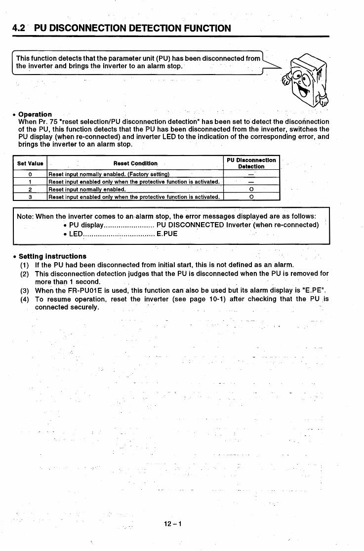
I
This function detects that the parameter unit (PU) has been disconnected from the inverter and brings the inverter to an alarm stop.
4.2 PU DISCONNECTION DETECTION FUNCTION
:@$j\f z
PU Disconnection , Detection
Set Value Reset Condition
0 1
1
Reset input normally enabled. (Factory setting) Reset input enabled only when the protective function is activated.
- -
i i
2
z
Reset input normally enabled. 0 3 Reset input enabled only when the protective function is activated. 0
I i
Note: When the inverter comes to an alarm stop, the error messages displayed are as follows: PU display ........................ PU DISCONNECTED Inverter (when re-connected) LED .................................. E.PUE
Setting instructions (1) If the PU had been disconnected from initial start, this is not defined as an alarm. (2) This disconnection detection judges that the PU is disconnected when the PU is removed for
more than 1 second. (3) When the FR-PUO1 E is used, this function can also be used but its alarm display is "E.PE". (4) To resume operation, reset the inverter (see page 10-1) after checking that the PU is
connected securely.
.. - . , ~- . - . . . .
c. . - i f . .
. .
h
b
12-1 b
b
\

4.3 ADJUSTMENT OF THE FREQUENCY SElTING SIGNALS "BIAS" AND "GAIN"
The bias and gain functions are used to adjust the relationship between th input signal entered externally and the output frequency, e.g. 0 to SVDC, 0 to 1OVDC or 4 to 20mADC.
5) Using the numeral .......... The data on the right is dis- keys, enter 10. played.
Before making adjustment, make sure that the set value of Pr. 73 "0 to 5V, 0 to 1OV selection" is "0"
...... The voltage need not be applied across terminals 2 and 5.
(factory setting: O-to 5 ~ ) .
Adjustment procedure 1 (without a voltage applied across terminals 2 and 5) (1) Setting of the frequency setting voltage bias
,
1) Press the [PU OP] key. ... The frequency setting screen is displayed.
2) Press the [SET] key. ....... The inverter is put in the parame- ter setting mode.
3) Using the numeral ........... The data on the right is dis- keys, enter 902. played.
4) Press the [READ] key. .... The current set value of Pr. 902 is displayed.
Display
f I I
I I 4) 6)
9)
1 6) Press the (WRITE] .......... The set value is stored into mem-
key. ory and bias setting is complete.
I
1 I
(To the next page)
1.3 - 1
...... The bias setting is 10Hz.
v
If the voltage is being applied across terminals 2 and 5 at this time, the bias setting as shown above.

(From the preceding page)
(2) Setting of the
...... The voltage need not be applied across terminals 2 and 5. At this time, the 5V (1OV) in the inverter is used as the set voltage.
f
V The adjustment of the frequency set- ting voltage bias and gain is complete.
0 5
b
b
Note: 1. The current input (Pr. 904, Pr. 905) can also be set in a similar manner. 2. Pr. 903 remains unchanged if the value set in Pr. 20 "acc./dec. reference frequency" is
changed. 3. The FR-PUOI may also be used to adjust the frequency setting voltage bias and gain and
current bias and gain (C-2 to C-5). For full information, see the FR-Z series instruction manual.
13-2

I-
- .
Adjustment procedure 2 (any point is adjusted with a voltage applied across terminals 2 and 5) (1) Setting of the frequency setting voltage bias Display
I 1) Press the [PU OP] key. ... The frequency setting screen is displayed.
. _
r
-1)
- -
D 2) Press the [SET] key. ....... The inverter is put in the para-
meter setting mode.
3) Using the numeral ........... The data on the right is dis- keys, enter 902. played. -
1 I I
- .
I
4) Press the [READ] key ...... The current set value of Pr. 902 is displayed. The preceding set value is displayed.
The current set voltage across terminals 2-5 is displayed in 96. The displayed value is changed according as the set voltage.
I (In this example, the voltage of 1V is applied.) The value '0' selected in Pr. 73 (SV in this example) is 100%. 1
1 - I I
...... Adjust the set voltage. When the voltage set is lV, the bias setting is as follows:
f
I OH V
1 0 ' 1v
7) Apply the voltage of OV. ...... Since 10Hz is set against OV in this example, OV is applied. (The % value for EXT changes.)
8) Press the [WRITE] .......... The set value is stored into mem-
The bias setting is complete as shown below:
ory and bias setting is complete.
I I I f
I OH2 v
V (To the next page) 0
-13:- 3

Setting of the
setting voltage gain
frequency
9) Press the [SHIFi] key, ... The current set value of Pr. 903 then the [READ] key. is displgyed. , ~ -__
r ,
. . . . . ..-. . . . . . . . . a --. . . - . I 1 < - - J . - * - a , . . '
The preceding set value is displayed.
The current set voltage across terminals 2 and I- .
1 The value selected in Pr. 73 (5V in this example) is 100%.
A . ........... 10) Using the numeral The data on the right is dis- - _ - *
keys, enter SO. - + played.
-- _.
1 5 is displayed in %. The displayed value is changed according as
- the set voltaae. . - I -
11) Press the [WRITE] key. .. - I - - .. The cursor (G) moves to the set voltage. . v *
- _ Increase the voltage across termi- nals 2 and 5 until 100% is - _
3) Press the [WRITE] key. ..'The set value is stored into mem- I ,
ory and gain setting is complete.
i - - .
- ---
%#!!k4 ComDlete 100.0; may not be displayed. The setting is complete as shown .
Since50Hz is set against 5V in 12) Apply the voltage of 5 V. ...... I -this exa-mple, 5V is applied.
L 1 ., I
_I- - - * . t " 1
I ~ - - _ - . - - I
I I
I I below: 1
The adjustment of the frequency set:- 1 ting voltage bias and gain is complete. - . _
. . . . . . . . - -. . - - . . . . . . - . : :_ a i .
. - . - - . . i "
. . - . . : i - .
.~ .- . .
. . , . . -
. . .
, . . r ..
f
Note: 1. The current input (Pi. 904, Pr. 905) can also be set in-a similar-manner. 2. Pr. 903 remains unchanged if the value set in Pr. 20 "acc./dec. reference frequency" is
- - -- . - . changed. * .._
- . 3
. . . - . . . _ - . ... - - . . . . . . . . . . , :
. . . . . -- . . . . . . . __ . . . -_ .-. . . .-. . - . .
, . - I . _ I , . . . . . . . . . . 4 . . - . . . . . 1 ._. . ._ T r , : . . . I . % _.
. . . . . . . I . - i. . ~ . . _. , ..-
- -13-4
Y
. .--. . . . . . . r ,. _ ,
. -
. I

I
6) Press the [WRITE] .......... The cursor (e) moves to the set key. voltage.
Adjustment procedure 3 (any point is adjusted without a voltage applied across terminals 2
(1) Setting of the frequency setting voltage bias and 5)
Display
ter setting mode.
- - .. 1 .
7 ) 11)
The preceding set value is displayed.
displayed in %. -- -The-current set voltige across terminals 2-5 is
The value selected in Pr. 73 (5V in this example) is 100%.
^I -
...... The voltage need not be applied across terminals 2-5.
I I . - I
in this example, 0% is entered.
1 8) Press the [WRITE] .......... The set value is stored into mem-
key. ory and bias setting is complete.
4 (To the next page)
The bias setting is as follows:
10
V
\ -13-5

(2) Setting of the frequency setting voltage
7 -IJ The preceding-set value is displayed. 9) Press the [SHIFT] key, ... The current set value of Pr. 903
- The current set voltage across terminals 2 and then the [READ] key.
I
is displayed.
5 is displayed in %. . The displayed value is changed according as
. . . . . ~-
I . ~
1 the set voltage. . _
I The value selected in Pr. 73 (5V in this example) is 100%. 0) Using the numeral ........... The data on the right is dis-
keys, enter 50. played ._
I
I. I I
I
1) Press the [WRITE] key. .. The cursor (e) moves to the set voltage.
12) Using the numeral keys, enter 100.
~~
3) Press the [WRITE] key. .. The set value is stored into mem- . " . ory and gain setting is complete. t
I The adjustment of the frequency set- ting voltage bias and gain is complete.
...... The voltage need not be applied across terminals 2 and 5.
...... Since 50Hz is set against 5V (100%) in this example, 100% is entered.
-The setting is complete as shown below:
f 4
(0%) ( 100%) ~~~~ ~
Note: 1. The current input (Pr. 904, Pr. 905) can also be set in a similar manner. . 2. Pr. 903 remains unchanged if the valueset in Pr. 20 "acc./dec. reference frequency" is
changed.
l3-- 6

4.4 SELECTION OF MAGNETIC FLUX VECTOR CONTROL
Magnetic flux vector control can be selected by setting the capacity, nu of poles, and type of the motor used. Magnetic flux vector control is effective when large starting and low-speed torque is required or when the load varies considerably. c
" t I . 1 . . _
Conditions for selecting mag- . When the following conditions are met, magnetic' flux vector netic flux vector control control can be utilized efficiently. When any -of -the following
conditions cannot be satisfied, faults such as torque shortage and - speed fluctuation may OCCUF. In this case, select V/F control. I . - , - -
. - _ _
i *I _.._ . . . - . . . . .
. . . . - . . . . . . . . c
- . -
Cond itio ns> The motor-capacity is equal The number of motor poles is to or one rank lower than the of 2,4, or 6. (4 poles only-for inverter capacity: - I . . _ _ ' ' the constant-torque motor)
B The type of the motor is the . Single-motor operation (one Mitsubishi standard moto-r ~ motor for one inverter) is per- (3.7kW or more) or Mitsubishi formed.
- condant-torque motor (200vr 0 The wiring. I-ength b-etween class 4-Pole motor is used the inverter and motor is less with3.7kW to 55kW). When than 30m.
.-another motor is used, use .L - I ^ * _ -- _ _
3 ,page - . 14-2. . --[see page 14-3. . i
the auto tuning function _onA If .the- length -is Over 30m,
Magnetic flux vector control selection method
- .- . . . . . . - - .
Set motor rated kW (a _value other than 9999) in Pr. 80 (motor capacity) and number of poles in Pr. 81 (number of poles) to select the magnetic flux vector control. (When 9999 has been set to either of Pr. 80 and Pr. 81, V/F control is selected.) When a Mitsubishi constant-torque motor (SF-JRCA, SF-JRC) is used, set 'T' in Pr. 71 "applied motor". When the previous Mitsubishi constant-torque motor (SF-JRC) is -used, special parameters or auto-tuning must be set in addition to the above parameters. For more information, see page. 15-1. By switching on/off the signal across te inals RT and SD during a stop, operation can be switched between the V/F control and magnetic flux vector control. Switch the signal off to select the
-
magnetic flux vector control (Pr. 71 = 12, 14, 16). n Note: Precautions for magnetic flux vector control
1. The degree of speed fluctuation correction is slightly
2. There is a delay of 0.1 to 0.2 sec at start. lower than in V/F control.
<Applications appropriate for magnetic flux vector control> B Machines which require
Machines which require low
Machines where the load large starting torque fluctuates widely
speed torque
1 Magnetic flux vector control is not appropriate for ma- chines where speed fluctuation at low speed is not al- lowed, e.g. grinder, wrapping machine.

Parameters related to mag- netic flux vector control .
V/F:control is selected.
Motor capacity (kW) is set. Motor
capacity 80
81
0 VIF control is selected. Number of motor poles is selected. Switch on the signal across terminals RT-SD to select V/F control if the number of motor poles has been set. (Control is switched at a stop.)
12: 2-pole motor 14: &pole motor 16: 6-pole motor
Standard motor Constant-torque motor Standard motor
_ -
Number of motor
poles
4
- _-I
Applied motor
. . . ,- I .
. . . .
. . . . I . . .
., . . . _ . .- . - . .
- .
13 to 16, 20 **
motor Standard motor
motor
motor Delta constants
. -. . . . . . . . --. ....... - I - . . - - . . . . . . . . . . . . . . . . . . .
. *~
. . .
, . - ~
*- The electronic overcurrent protection - . characteristic is-also _ - set - ~
**I 20,23 and 24 are also av ble for-setting-but must not be set ; simultaneously.
*. as they are used for setting-by the manufacturer.
Note: The output torque may 'reduce when the optional noise reduction reactor (FR-BOL) or surge voltage suppressing filter (FR-ASF-H) is connected between the inverter and
' the motor. (See page 28-10) . . - ._ I - -
. . . ! ' , . '
.. __ _ _ _ _ _ _- - .- - -. - ~ - - . - . . . . . . . . . . . .- - .... _"._
. . . . . . . . . . . . . . . . . . . . . . . . . . . . . . . . . . . . . . . . . . . . . . . -
.-
14-2

Compatibility with the Mitsubishi constant-torque motor
When a Mitsubishi constant-torque motor is used, the setting depends on the motor type (there are two types). Check the type of the motor used.
- - - - ~~ - -
Rating plate (SF-JRC) - - Rating plate (SF-JRCA)
3.3kW 4 POLE TYPE SF-JRC
HERfZ 60 60 1325
'VOLT . 200 - 220 I FRAME
THREE PHASE INWCTlON MOTOR THREE PHASE INDUCllON MOTOR
132s INV-INPUT HZ W 6 0 60
,INV-INPUT VOLT 200 220 FRAME KW 0.28- 6.5 -4.9 5.5 RATINQ C O M
HERTZ 3- Bo- 120 120 INS CLASS F -. . ~
PPM 1730 1740 INS CLASS F 60-120 HZ 5.5kW AMB TEMP . 40% 6- 6OHZ 3.0 kgm , BEARINQ .
!
~- _ _ I
AMP 23 22 1 RATING C O M
AMP 21.5 23.4- 22.6 22.0 thin 90- 1800 - 3520 3630 kg-m 3.0- 3.0- 1.35 1.5
AMB TEMP 40%
BEARINQ 6208LZ lJlS C AOOA I 6208LZ I
Mitsubishi Constant- I Torque Motor TYPe
.- - - JP M JC A I 6 2 0 N I
Parameter Set Value '
81 (number of I Special Setting Pr. 71 (applied motor) I Pr. 80 (motor capacity) I motor D o l e s \
____
SERIAL C91300001 I MlTSUBlSHl ELECTRIC CORPORATION. JAPAN r-1 - - . SLI I I 897430-01
Required (see below) 4
4
Set the capacity of the motor used.
Set the capacity of the motor used.. .
SF-J RC 1 (constant-torque motor)
SF-J RCA 1 (constant-torque motor) - i
. .
. , .
JIS C 4004 JP44 JC4 I 620722
SERIAL C91300001 I MlTSUBlSHl ELECTRIC CORPORATION. JAPAN - 896071-01
I I I I t - -
(1) Selection method
(2) Special parameter set values for use of the SF-JRC constant-torque motor
Set the parameters to the values-indicated below according to the capacity of the constant-torque motor. Note that if the values set are not as indicated below, torque shortage or overcurrent alarm may occur.
- ' Parameter Set Values Pr. 81 Pr. 90 (Wiring length
30 to 100m)
SF-JRC Pr. 71 Pr. 80 Capacity (kw) (applied (motor (number of Pr. 89 Pr. 90
motor) capacity) motor poles)
37 1 37 4 188.1 0.01 5 0.01 5+0.0002193x 45 1 45 4 164.7 0.01 6 0.01 6+0.0002193x
Note: 1. Applied motor: Mitsubishi's previous type 200V series 4-pole constant-torque motor (SF-JRC) only
2. Wiring length of over 30m: Calculate the value (n) of Pr. 90 with reference to the above table, assuming that x = 30 to 1OOm.
3. If the parameters are set as listed above, torque shortage or over current alarm may occur according to the motor used. In such a case, make fine adjustment of the Pr. 89 and Pr. 90 settings.
'14 - 3

Constant-Torque Motor Magnetic Flux Vector Control V/F Control I (FR-A2Ol) (All inverter models) 1
Operable by standard setting (Pr. 80, Pr. 81, Pr. 71) SF-JRCA (new type) Operable by standard setting
(Pr. 71)
(3) Setting method of the special parameters
The special parameters must be set in the following procedure,-otherwise the values of Pr. 86 to Pr. 90 cannot be read. 1) Set 801 in Pr. 77. (Note) 2) Change the setting of the special parameters in (2).
- 3) Set 0 or 1 in Pr. 77 (return to the previous set value). Note: When 801 is set in Pr. 77, the values of Pr. 82 to 99 are also displayed together, but these
parameters must not be changed. Otherwise, the inverter may be damaged.
Precaution : Nole that a sufficient motor torque may not be provide depending on the inverter control method.
Operable by torque boost adjustment (Torque shortage or overcurrent occurs in the standard setting)
Operable by special setting ((2) on preceding page) SF-JRC (old type)
(Pr. 80: motor capacity, Pr. 81 : number of motor poles, Pr. 71 : constant-torque motor selection) i
c
>
. .
_ . *, . i
i 4
14-4
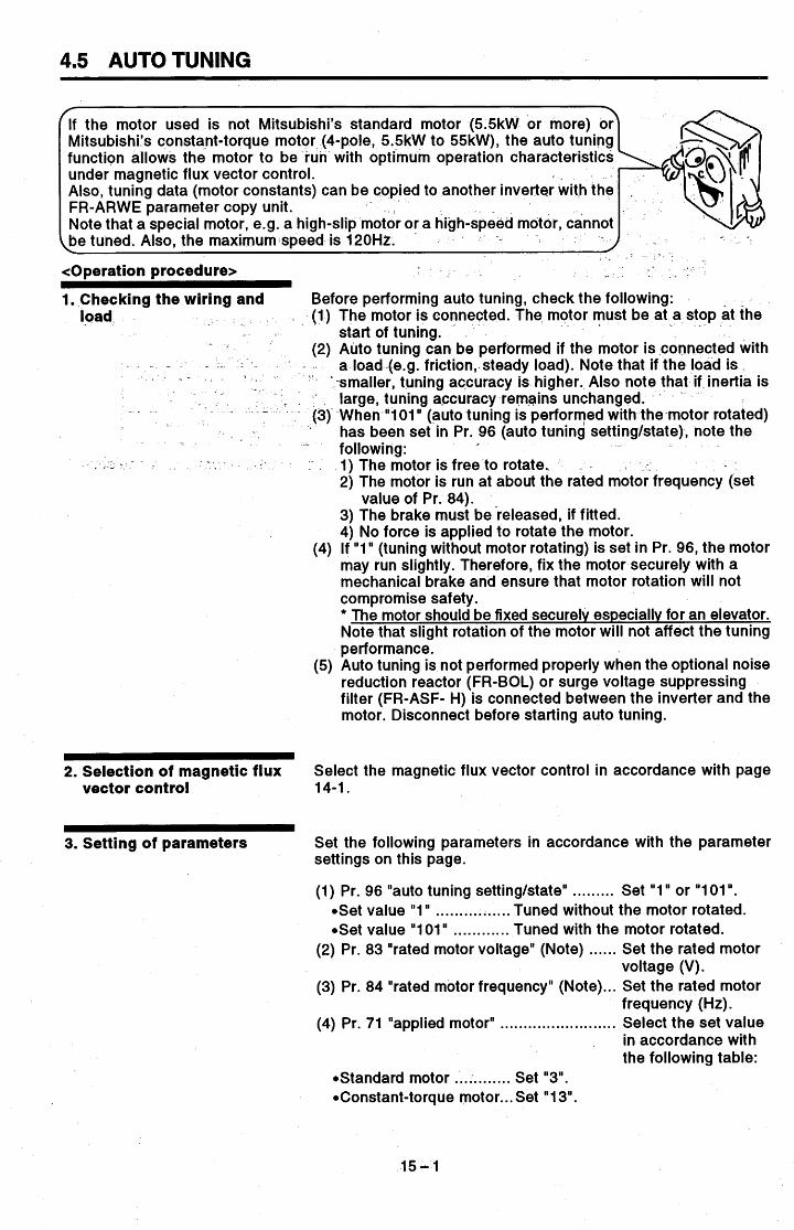
4.5 AUTO TUNING
r 7
If the motor used is not Mitsubishi's standard motor (5.5kW or more) or Mitsubishi's consta-nt-torque mot -pole, 5.5kW to 55kW), the auto tuning function allows the motor to be ith optimum operation characteristics under magnetic flux vector control. Also, tuning data (motor constants) can be copied to another inverter with the FR-ARWE parameter copy unit. Note that a special motor, e.g. a high-slip motor or a high-speed motor, cannot
.be tuned. Also, the maximumispeed is 120Hz. 1
<Operation procedure> . . - . *
1. Checking the wiring and Before performing auto tuning, check the following: (1) The motor is connected. The motor must be at a stop at the
(2) Auto tuning can be performed if the motor is ,connected with
'-smaller, tuning ac'curacy is higher. Also note that if inertia is - large, tuning a,ccuracy remains unchanged. '
~ (31 When "101" (auto tuning is performed with the-motor rotated) ' has been set in Pr. 96 (auto tuning settingktate), note the
- following:
2) The motor is run at about the rated motor frequency (set
3) The brake must bereleased, if fitted. 4) No force is applied to rotate the motor.
(4) If "1" (tuning without motor rotating) is set in Pr. 96, the motor may run slightly. Therefore, fix the motor securely with a mechanical brake and ensure that motor rotation will not compromise safety. * The motor should be fixed securely especially for an elevator. Note that slight rotation of the motor will not affect the tuning performance.
(5) Auto tuning is not performed properly when the optional noise reduction reactor (FR-BOL) or surge voltage suppressing filter (FR-ASF- H) is connected between the inverter and the motor. Disconnect before starting auto tuning.
- . load start of tuning.
- - - + - . - ___ _ _ - - a load-(e.g. friction, steady load). Note that if the load is
- .
n - - , . . 1) The motor is free to rotate. I .
value of Pr. 84).
~~
0 2. Selection of magnetic flux Select the magnetic flux vector control in accordance with page vector control 14-1.
3. Setting of parameters Set the following parameters in accordance with the parameter settings on this page.
(1) Pr. 96 "auto tuning settingktate" ......... Set "1" or "1 01 ". .Set value "1" ................ Tuned without the motor rotated. .Set value "1 01" ............ Tuned with the motor rotated.
(2) Pr. 83 "rated motor voltage" (Note) ...... Set the rated motor
(3) Pr. 84 "rated motor frequency" (Note) ... Set the rated motor voltage (V).
frequency (Hz).
in accordance with the following table:
(4) Pr. 71 "applied motor" ......................... Select the set value
.Standard motor ............ Set "3".
.Constant-torque motor. .. Set "1 3".
.15- 1

Note: Pr. 83 and, Pr. 84 are displayed only when magnetic flux vector control has been selected (Pr. 80, Pri 81). Set these parameters according to the rating plate of the motor. When there are two or more rated values for a standard motor, etc., set 200V/60Hz or 400V/60Hz.
W Parameter settings
constant R1
Motor
R2 constant
Motor - constant
L1
0 to
9999,O 9999
1O.OOOCl io.oooCl
9999,O 9999 0 to
1000;OmH 1000.0mH
to 10.00021 10.000Q
to 0 to
to
0, 1, 101 '3
~ Auto tuning is performed without the motor rotated.
Auto tuning is performed with the motor rotated. 101,3
. .
. -
. - 1 . - - . . .
Desctlptlon
0
-
*4 200
(&point flexible V/F characteristic)
'Auto tuning setting' is
Applied motor '1
Standard motor
toraue motor
Auto tuning data read/ change setting is enabled to 16.20
Standard motor
torque motor connection Direct input
of motor con- stants is en- abled
connection l6 Constant- torque motor
. .
. . .~
Rated I 0 to I ' 0 to 1 'No auto tuning' is selected. Rated motor volt- IOOOV IOOOV age (v) is set.
Rated motor
irequency z& - Rated motor frequency (Hz) is set. 20Hz
60 . -
0 90'
0 91 -
0
- 92 Tuning data '2
93 0 Motor
constant L2
Motor constant
X
Auto tuning setti n g l state
. . . I .
9999,o 1-1 to 100%
0 94
1- 1000% -1 I 0 I 'No auto tunina' is selected. 0
96
- . *l.: The electronic overcurrent protection characteristic is ' - selected at the same time. *2: The values measured by auto tuningare set automatically. *3: Select V01" to increase tuning accuracy. "4: The factory setting for the FR-A241 (400V) series is 400V.
- -
15-2

4. Switching the auto tuning In the PU operation mode, press the (FWD] or [REV] key. In the external operation mode, turn on the start switch (connect command ON
Auto TUninQ Settinq 1 : Mode in which the motor does not rotate 101: Mode in which the motor rotates
terminals across STF or STR and SD).
Note: 1. When "1 01 " is set in Pr. 96, be careful to avoid hazard
2. During auto tuning, the inpuVoutput terminals are made - because the motor rotates.
vaIid/invalid as indicated below:
Time Approx. 10 seconds
ADDrOX. 25 seconds '1
. .
. ...
- , . . - . . - - . - . I . .
0 Valid Terminals 1 Invalid Termlnais I I STnP I -. -. I R W R W '
AU
OH
RT, JOQ, CS I MRS I 2.1.4
s RES
c.
a L E t 0
Valid Terminals
RUN OL I PF
FM, AM A, 0, C
invalid Terminals
su FU
To force the motor to stop during tuning Terminate tuning use the MRS terminal, RES terminal, or [STOP] key.
3. Be careful especially when the RUN signal has been used to create a mechanical brake releasing sequence.
5. Tuning state monitoring - During tuning, the value of Pr. 96 is displayed on the main monitor ~ and level meter of the PU as indicated below. As on the PU, 1,2,
. 3,9, 91, 92, 93, 102 or 103 is shown on the inverter LED. (When - Pr. 51 = "1" (factory setting))
tPU main monitor . (In case of inverter trip) 3. Error-acti-
Progress Completion vated End 1. Setting 2. Tuning in
Display 81f r n P Pu
. . .
.PU level meter --
Indicates tuning progress with 0% (start) to full-scale 100% (end). .Inverter LED (In case of inverter trip)
Corn letion y>!txi_~_ng-: Displayed I I
1 - 9 - 9 - 9 9 I
Error-acti- ' 0 Setting Pro ress
.. - I_
101 + 102 103 -1,911 9 l -111
- value
15-3

Error Displav Cause 9 Inverter trip
91
92
93 Calculation error
The current limit (stall prevention) function has been activated.
of the rated value. The converter Output "Itage has dropped to 75%
b
- Corrective-Action Set again.
the acceleration~deceleration time.
Check the variation of the power supply voltage.
Set again.
Pr. 90 Pr. 91 Pr. 92 Pr. 93 Pr. 94 Pr. 82
Motor constant R1 0 to , 9999 1 9999 Motor constant R2 0 to , 9999 1 9999 Motor constant L1 0 to * , 9999 1 9999 Motor constant L2 - O t o * * * * , 9999 1 9999 Motor constant X 0 to * * * 9999 . 1 9999 Motor constant exciting current 0 to ; 9999 1 9999
b
D
b
I
P
A
i! I Note: If OL (stall prevention) occurs during auto tuning, auto tuning cannot be performed. I [Optional Setting of Motor Constants]
The motor constants (Pr. 82, Pr. 90 to 94) may either be set as appropriate by'reading and changing the data measured by auto tuning,-or without using the auto tuning data:
Setting the motor constants by reading and changing the auto tuning data
<Operation procedure> 1. Change the set value of Pr. 77 "parameter write disable selection" to "801 'I. Only when the settings
of Pr. 80 and Pr. 81 are other than "9999", the parameters of the motor constants (Pr. 82, Pr. 90 to 94) can be displayed. Though the parameters (Pr. 83 to 99) other than the motor constants (Pr. 82, Pr. 90 to 94) may also be displayed, they are to be set by the manufacturer and must therefore-be set carefully without mistake.
Standard motor: Set "4". Constant-torque motor: Set "1 4". 2. Set Pr. 71 "applied motor"1 as indicated below: ! I .
3. In the parameter setting mode, read the following parameters and set the required values (Note 1):
. . I ,
. I .
. . - . .
- ,
. . , . I
. .
_ . . * . . . . .
. . . .
, . . . . . . . .
15-4

Note: 1. Only when the settings of Pr. 80 and Pr. 81 are other than "9999" (magnetic flux vector control is selected), Pr. 82, Pr. 90 to 94 can be read.
2; Set '9999" in Pr. 82, Pr. 90 to 94 to use the standard motor constants (including the constant- torque motor).
3. Set '"3" (standard motor) or "13" (constant-torque motor) in Pr. 71 to use the motor constants ' measured by auto tuning.'If "4" or "14' has been set in Pr. 71 and the motor constants changed, . the original data measured by auto tuning remain changed.
When setting the motor constants, see the following setting-example:
When the Pr. 90 "motor constant R1" value displayed is 2516 and i t is desired to increase the Pr. 90 value slightly (5%), set 2642. (i.e. 251 6 x 1.05 = 2641.8) in Pr. 90. (The value displayed has been conve-rted into internal data for internal .use. Hence, there is no significance if an optional value is simply added to the displayed value.)
.
- I 1 . +Setting example:
- -4. The motor-constants measured by auto tuning have been converted into internal data (****).
. . . a
Star Connection Delta Connection Motor - Motor
Standard motor 5 6
15 16 Set value Constant-torque
motor
- .
I *, .
3. In the parameter setting mode, read the following parameters and set the required values:.
'3 * .
4. Set Pr. 84 "rated motor frequency" with reference to the following table:.
Pr. 84 . - _ _ 50 to 120Hz,9999 0.0lHz - ~. - 9999 Rated motor
. frequency . - I - --- . _ "
5. Return the setting-of Pr. 77 to the original value. . - -
Note: 1. Only when the settings of Pr. 80 and Pr. 81 are other than "9999" (magnetic flux vector
2. Set "9999" in Pr. 90 to 94 to use the standard motor constants (including the constant-
3. If the "star connection" or "delta connection" selected in Pr. 71 does not match the actual
control is selected), Pr. 90 to 94 can be read.
torque motor).
motor, proper magnetic flux vector control will not be carried out.

~ . . . . . . .
Pr. 90 Pr. 91 Pr. 92 Pr. 93 Pr. 94
. . Entering- the motor constants- of Pr., 92 and 93 in [mH]
1. Change'the set value of Pr. 77 "parameter write disable selection" to "801'". Only when the settings of Pr. 80 and Pr. 81 are other than "9999", the parameters of the motor constants (Pr. 90 to 94) can be displayed. Though the parameters (Pr. 82 to 99) other than the motor constants (Pr. 90 to 94) may also be displayed, they are to be set by the manufacturer and must therefore be set
.carefully without mistake.
<Operation procedure>
- - 2. Set Pr. 71 "applied motor" - as _ . indicated below:
Standard motor: Set "0". - Constant-torque motor: Set% 11.
' -
Motor constant r l 0 to lon, 9999 0.00152 9999 Motor constant r2 0 to 10n, 9999 0.00152 9999
Motor constant x2 0 to lOOOmH, 9999 - O.lmH 9999 Motor constant x 0 to loo%, 9999 0.1 % 9999
Motor constant xl . 0 to 1000mH, 9999 O.lmH 9999
3. In the parameter setting mode, read the following parameters and set the required values:
motor - frequency Pr.84 50 to 120Hz, 9999 0.01 Hz 9999
- - \ /
4. Set Pr. 84 "rated motor frequency" with reference to the following table:
. (1
I I I Increment 1 Factoiy Settfnq Pr,-No., Name, +. I Range
1
- / 8. Be careful as the motor-.may run suddenly. ' When auto tuning isused in vertical lift applications, there is a possibility that a load may drop due to torque shortage.
5. Return the setting of Pr. 77 to the original value.
Note: 1. -Only when the settings of Pr. 80 and Pr. 81 are other than "9999" (magnetic flux vector
2. Set "9999" in Pr. 90 to 94 to use the standard motor constants or constant-torque motor control is selected), Pr. 90 to 94 can be read.
constants.
I
-1 5 - 6

4.6 PROGRAMMED OPERATION FUNCTION
frequency and direction of rotation set in advance.
4.6.1 Preparation
Setting of operation mode and output terminals (Pr. 79, Pr. 76)
. * . -
W'i r in g
- - .
-' . _ . , I
To perform programmed operation, set- "5" (programmed opera- tion) in Pr. 79 "operation mode selection" and "3" (programmed operation output) in Pr. 76 "alarm code output selection".
Timer time-out output signal
With 3 set in Pr. 76, the temi- nals operate as indicated on
I _
t the left. . .
s .
When "5" (programmed operation) is set in Pr. 79, the following terminals are made valid-and invalid and are used for pro- grammed operation: -
I I JOG I
Note: When the battery pack for programmed operation (FR- EPD) is fitted, note that the terminals used for pro- grammed operation are not as indicated above. (For details. see the option instruction manual.)
During programmed operation, the inverter cannot be operated in any other operation mode. When the programmed operation start signal (STF) and timer reset signal (STR) are ON, the operation mode cannot be switched between PU operation and external operation. When "5" is set in Pr. 79, the following functions are unavailable if the corresponding inboard option is fitted:
(1) Orientation control (2) 12-bit digital input (3) PI control
16'-1

Programmed operation time unit selection (Pr. 200)
Set the time unit for programmed operation. Select either of "minute/second" and "o'clocWminute" in Pr. 200. *
1 Set Value 0 (factory setting)
1 2 3
. .. - _ Description Minutekecond unit (voltage monitor) O'clocWminute unit (voltage monitor) Minute/second unit (reference time of day monitor) O'clocWminute unit (reference time of day monitor)
2oo Set Value
Note: When 2 or 3 is set in Pr. 200, the reference time-of-day monitor screen is displayed instead of the voltage moni- tor screen.
-
,
Pr. 231 Setting Range Pro Value 2oo Set Pr. 231 Setting Range
Setting of reference time of day (Pr. 231)
0 (factory setting)
1
PJ
Max. 99 minutes 59 seconds
Max. 99 o'clock a
59 minutes
2
3
Max. 99 minutes 59 seconds
Max. 99 o'clock 59 minutes
. -
I
The FR-A201 E has an internal timer (RAM). When the reference time of day is set in Pr. 231, programmed operation is started at this time of day.
(1) Setting range The time unit depends on the set value of Pr. 200.
Note: The reference time-of-day timer starts the timing of the reference time of day when both the start signal and group select signal are entered. Set the reference time of day in Pr. 231 when both signals are on.
~ ~~ ~~~ ~~~ ~~ ~~
. -
(2) Resetting the reference time of day The reference time of day is cleared (returns to--"O")sby switching on the timer reset signal (STR) or resetting the inverter (see page 10-1). Note that the reference time-of-day value set in Pr. 231 is also reset to "0".
.Instantaneous error: k0 .16~
.Cumulative error: k50ppm (according to the accuracy of the
_ .
(3) Timer accuracy
crystal oscillator) - -
- . FR-A201E independent error: Max. 4.5s-per day ~
(24Hrx60x60x50ppm=4.32s) I
f
~ . _ _ . ~. . . 1 . - . . I .
. . . , - - - .
. . . . , . - . I 1 .
- . . . .
I 16-2

Pr 221 I
Note: If either of Set and Time is "9999", no - setting is made. -
1) Press-the [PU OP] ....... :.. The frequency setting screen is . .> key.-' displayed. r r", ...-*
Display
I
L 1
I L
I I
4) Type 1 (forward ............... V u is displayed at Direction and - rotation) and press the, stored into memory.
I - [WRITE] key. (Note 1)
2) Press the [SET] key. ....... The inverter is put in the parame- ter setting mode.,
.--
6) Using the numeral ............ '4.30" is displayed at Time, the keys and [READ] key, set value is stored into memory, enter 4.30 and press the and setting is complete. [WRITE] key. (Note 2)
and press the The current set value is shown [READ] key. on the display.
. .
...... Max. setting: 9959 Press [READ] to enter O:' at Time.
a
5) Type 30 ( 3 d k ) and ......... "30.00Hz' is displayed at Set and f . press the [WRITE] key.
(Note 1) stored into memory.
I 7) Press the [SHIFT] key to move to the next parameter (Pr. 202), and press
the [READ] key to display the current set value. Then, press the [SHIFT] key to advance to the next parameter.
I Note : 1. To make a stop, write "0" in the rotation direction and frequency. Set "9999" for no setting. 2. An error will result if 4.84 is entered (in excess of 59 minutes or 59 seconds). I
16-3

- - _ .- . -
- _ _ -
Forward rotation +
. Reverse 4 rotation .
- _ _ - - - - 0
Time of day t 30 Hz . - , /
No. . Operation Parameter Setting 1 Forward rotation, 20H2, 1 o'clock 0 minutes Pr. 201=1, 20, 1 :00 2 Stop, 3 o'clock 0 minutes Pr. 202=0, 0, 3:OO 3 Reverse rotation, 30Hz, 4 o'clock 0 minutes Pr. 203=2, 30, 4:OO 4 Forward rotation, lOHz, 6 o'clock 0 minutes Pr. 2044, 10, 6:OO 5 Fotward rotation, 35Hz, 7 o'clock 30 minutes Pr. 2054, 35, 7:30 6 Stop, 9 o'clock 0 minutes Pr. 206=0, 0, 9:00
-
- - _ _ _
4.6.3 Details of the Functions
Parameters used ~ ~ - -
I
, - - Factory Setting
. . . - . . . . . .
. . .
* ' - .
.. - . . . . -
. . , *
. . . . + . .
Remarks -
Pr. No.
200
201 to 230
23 1 -
9999
. ,Name
0-minutekecond unit/ voltage monitor 1 -o'clock/minute unit/ voltage monitor 2-minute/second unit/ reference time of day monitor 3-o'clocWminute unit/ reference time of day monitor Rotation direction setting 0-stop, 1 -forward rotation, 2-reverse rotation
Frequency setting
Programmed operation
minute/second selection
_. D
- Programmed operation
program setting
Timer setting
lncrementd 'angel Unit
0 to 3
0 to 2-
0 to 400HZ 0 to
9959 0 to
9959 -
1
1
0.1 Hz
Minutes x secondi
- lTime of day setting
Reference time-of-day timer (RAM) (Notel)
Note: 1. When both the start signal and group select signal are -entered, the set value of Pr. 231 "timer setting" re- turns to "0". Set the optional time of day with both signals on. Note that if the start signal and group select signals are entered after setting the optional time of day, the Pr. 231 set value returns to "0" again.
2. Note that when the setting of Pr. 200 has been changed independently, the units of Pr. 231 and Pr. 201 to 230 change.
3. When 2 or 3 is set in Pr. 200, the reference time-of- day monitor screen is displayed instead of the voltage monitor screen.
8 . > i
-16-4

Input signals Name
signal
RH (group l ) . RM (group 2) !. . RL (group 3) 1 Group select
- . - . _ . .. - . . . . . - . . . .. - . - - -
. - . . . . .. . . - . . . -
.. ~
- . . .- .-- ~
. - . . . - . .
, . . ._ . _.- . .. .- . . .. - .
~. . . . .
. . . - . - . . - . . . .
Description
Used to select the
programmed operation-, _ _
group for.-- -
, - r
~~ ~~
Output signals Name . _
4.6.4 Operation
Description Signal Level Output on completion of
Ordinary operation
I -. ~ . < .
Permissible load
24VDC, 0.1A
Pe rmissi bls load
24VDC, 0.1A
~ . . , . .. -
. _
. . . . , . . . - . - - . . . .. . . - -. . . . . . . . -
. - , .. ~. . .
- , _ L . - _
- . . . - . . .
Only when Pr. 76=3
-
. .. - '
Time-out signal Inverter terminal (SU)
the operation of Open collector the selected output group and
Programmed ' Input'to start operation start programmed si nal STF o eration.
Group select signal Inverter terminal (FU, OL, IPF)
Siqnal Level
operation of corresponding group,s Open collector program and - output (isolated) cleared on
Photocoupler isolated
Re marks
May also be driven by transistor. When ic=l OmA, VeccOSV should be satisfied.
P hotocoupler isolated
P hotocoupler isolated
cleared on timer reset. Output during
ltimer reset. I
P,
- performed in sequence in accordance with the set- tings. When the operation of the group ends, a signal is output from the time-out
I output terminal. (The open - collector signal of SU is . turned on.) I
, - * . -
. - - (
" ,
- -
16-5
eration function with "5" set in Pr. 79. Programmed operation will not be per- formed if any of the group select signals is switched on during PU operation or data link operation.

Multi-group select operation
Repeated operation
When two or more groups are selected at ths same time, the operations of the selected groups are exe- cuted i n sequence of group 1, group 2 and group 3. For example, if group 1 and group 2 have been selected, the operation of group 1 is first carried out,
Start signal k k * STF Group 1 RH <--
Group 2 RM
and after that operation 'ends, the reference time of day is reset, the opera- tion of group 2 is.startsed, and the time-out signal (SU) is output after the operation of group 2 ends..
-~
. , . , - .
To repeat the operation of the same group, reset the timer using the time-out signal as shown below. 1) To repeat the operation of only
group 1
' ,
. . - L . . I
Inverter
FR-A I '
(Group2) RM (Group3) RL - -
- SF
1
To repeat the operation of groups land 2
Inverter
Note: If the inverter is powered down, then up (including a power failure or an instantaneous power failure) during the execution of the programmed operation, the internal timer is reset and the inverter does not restart if the power is restored. To resume the operation, turn the programmed operation start signal (terminal STF) off, then on again. (At this time, the reference time of day is zeroed. When it is required to set the reference time of day, switch the start signal on before setting.)
16-6

4.6.5 Programmed Operation Battery Backup (FR-EPD option)
To continue programmed operation at the occurrence of an instantaneous power failure, install this unit (FR-EPD) and start programmed operation.
Power failure period
m Operation at occurrence of+in-- (1) When a power fail- stantaneous power failure , , ure has occurred,
operation is contin- Power supply
ued as shown on the right with the
the power failure frequency
period eliminated.
operation contin- ues timing.
(2) If the group selected has been changed during the power failure, the operation of the group selected is started from the beginning after the power is restored.
(3) The battery is guaranteed for 10 years. If the BAT.E lamp is lit, change the battery.
I
operation during Inverter output
The internal timer for programmed is eliminated.
Setting of this period
3
(4) The operation is not performed if the power is restored when or after the time-out signal is output.
(5) If the power is restored after a long power failure period, programmed operation is not resumed. Perform group selec- tion and time setting again.
.Max. permissible power .......... 18 hours when Pr. 200 = "0" or "2" (minutekecond select ion). 30 days when Pr. 200 = "1 'I or "3" (o'clocklminute se- lect ion)
failure period
.16-7

4.7 5-POINT FLEXIBLE V/F CHARACTERISTIC
\ gqo\lf
Pr. 101 Pr. 102
Note: 1. The V/F 5-point flexible characteristic functions for V/F control only. 2. The V/F 5-point flexible characteristic does, not function when Pr. 60 (intelligent mode
selection) is selected. 3. The frequency voltage may be set optionally betweqn 0 and IOOOV, but output voltage is
clamped at the base frequency voltage if output frequency is beyond the base frequency. 4. Pr. 19 (base frequency voltage) must be set. (When Pr. 19 = 9999, Pr. 71 cannot be set
to 2 (5-point flexible V/F characteristic).) 5. If "2" is set in Pr. 71, Pr. 47 (second V/F (base frequency)) does not function. 6. When "2" is set in Pr. 71, the electronic overcurrent protection is calculated for a
general -purpose motor.
BCD input (gain) . o to 400Hz. 9999 1 VEI (first frequency voltage) o to IOOOV 0.1 0 Binary input (offset) 0 to 400Hz 1 VE2 (second frequency) 0 to 400H2, 9999 0.01 9999
0 V/F1 to 5 setting range - . - n
Pr. 103 Pr. 104
I Pr. 100 I BCD input (oftset) NvEl (first frequency) I O to 400HZ,9999 10.01 19999 I
Binary input (gain) 0 to 400HZ,9999 iVE2 (second frequency voltage) 0 to lOOOV 0.1 0 BCDbinaty selection 0, 1, 2, 3,9999 iV/F3 (third frequency) 0 to 400HZ,9999 0.01 9999
P r . 105 Speed feedback range 0 to 400Hr.9999 nVE3 (third frequency voltage) 0 to 100OV 0.1 0 Pr. 106 Feedback gain 0 to 100 aVE4 (fourth frequency) 0 to 400HZ,9999 0.01 9999 Pr. 107 Pr. 108 Pr. 109
Stop position command selection 0, 1, 9999 1/V/F4 (fourth frequency voltage) 0 to 1OOOV 0.1 0 Orlentatlon speed 0 to 30HZ RVES (fifth frequency) 0 to 400H2, 9999 0.01 9999 Creep speed 0 to 10Hz i V F 5 (fifth frequency voltage) 0 to 1OOOV 0.1 0
Note: The set values of Pr. 100 to Pr. 109 set when Pr. 71 is other than "2" are stored internally and remain unchanged if the set values are written with "2" set in Pr. 71. When the inboard option is added with "2" set in Pr. 71, the parameters set when Pr. 71 is other than "2" are made valid and the option operates with these parameters.
17-1

4.8 PU OPERATION INTERLOCK FUNCTION AND EXTERNAL SIGNAL-BASED OPERATION MODE SWITCHING FUNCTION
__ ~~
Connected 1 -
Disconnected
Connected. J
Disconnected
7 ~ __
The PU operation interlock function allows PU operation to be interlocked' depending on the ON-OFF of the terminal MRS signal. The external signal-based operation mode switching function allows the op- eration mode to be fixed depending on the ON-OFF of the terminal RH signal. These functions prevent the inverter from not starting operation under external command if the operation mode is left unswitched from the PU operation mode.
1
-
\
4.8.1 PU Operation Interlock Function
Forcibly switched to the external operation mode. (Note I)
Forcibly - switched to .. the external operation mode. (Note-1)
If the frequency setting and start ~
signalsof exter- nal operation are on, opera- tion is performed accordingly.
Remains stopped* ' ~
Remains stopped.
Running 1
Output stop
Output stop J
Run (Note 4)
external start signal.
Unswitchable to the Enable PU operation mode.
Note 2: Limited to Disable parameters that may
be rewritten during (Note 2, operation.
- 4
Disable Switchable t0 the Pu
Disable Note 3 Output Stopped.
Disable UnswitchableYo the
operation mode. 1
PU operation mode. J Disable
Disable Unswitchable to the PU operation-mode. - 1
-Disable
Disable 'peration mode. switchable to the PU
Note 4: If the fre-
is on, operation is per- formed accordingly.
1 Disable quency setting signal
stop
Running
Conne*cted :riz!iT:ote 3)
Connected Remains in the external
Disconnected
Disconnected p h e e ~ ~ ~ ~ l Connected :ri:!i;:ote
1 J-
1
-.
Set "7" in Pr. 79 "operation mode selection". Setting method _ _
The input signal MRS is assigned as the PU operation interlock signal. (When "7" is set in Pr. 79, MRS automatically operates as the PU operation interlock signal.)
In the PU operation interlock mode, the.f,ollowing functions are
PU operation interlock signal
Functions made valid:- . / . .
. , .. .
Set Value Terminals MRSSD
:onnected . .
Functlon, Operation . Output stopped during external operation. Switchable to the PU mode.
Parameter setting can be changed in the PU mode.
PU operation allowed. Forces the operation mode to be switched to the external operation mode.
External operation allowed. Switching to the PU operation mode disabled.
7
. -
lisconnected
The following table lists the functions and operations performed by switching on (connecting)/off (disconnecting) the external sig- nal (across terminals MRS):
Status l p a ~ ~ t e r l Remarks 'atlon Status
I I Unswitchable to the PU operation mode. Note 1: Switched independently of the
Remains stopped. stop
U
Runnin
Remains in . the external 7 1 1 Discovnected I
:xter- al
1 IRemains in Connected the external
Disconnected ion
18-1

. c _I
. .
. .. . . _ . I
I . . > . . . .
, . . . . . . ... -
. - - . . . . .
. .. - . d . . I
Note: 1. When the signal across terminals MRS and SD is switched on and the value of Pr. 79 is then changed to other than 7 in the PU operation mode, that signal functions as the ordinary signal (output stop), not as the edit enable signal. Also, as soon as the value of Pr._79 is changed, the ordinary mode switching is
. carried out. 2. When Pr. 79 = 7, the link operation (computer link, PC
link) function cannot be used. Also, the inverter is put in the external operation mode if Pr. 125 = 1 (link mode at power on).
. 3. If the signal across STF or STR and SD is on, the - external operation mode cannot be switched to the PU operation mode when the signal across MRS and SD is on.
- 4. When 7 is set in Pr. 79 and the signal across terminals MRS and SD is switched on and is then switched off
-during PU.operation, the inverter is switched to the , . ' external operation mode independently of the external
terminal (STF, STR) signal state. Therefore, when the signal across terminals MRS and SD is switched off with either of the STF and STR signals on, the motor is run in the external operation mode.
5. The ordinary MRS function is invalid for the PU opera- tion mode.
6. The above description all applies to a case where Pr. 17 = 0 or 1 (MRS terminal normally disconnected). When Pr. 17 = 2 or 3, ON changes to OFF and OFF changes to ON in the above table and description.
7. When the PU operation mode is forcibly switched to . the external operation mode, the PU is internally reset
once to secure the monitor screen. 8. The above function is not available for the FR-PUO1 E
and "7" cannot be written to Pr. 79. 9. Atlhe occurrence of any alarm, press the STOP key
in the PU operation mode to reset the inverter. The inverter cannot be reset in the external operation mode and must be reset in the PU operation mode.
,
.
18-2

4.8.2 -External Signal-Based Operadon Mode Switching Function
Setting method
- -
- - i ' Set "8"" in Pr.- 79 "operation mode selection".
- - External signal-based opera- tion mode switching signal
The input signal RH is assigned as the external signal-based ~ operation mode switching signal. (When "8" is set in Pr. 79, RH
automatically operates as the external signal-based operation .mode switching signal.)
I ; . ,
Functions. In the external signal-based operation mode switching mode, - * r the following functions are made valid:
set Value Fixed Mode Remarks Terminals
RH-SD
Connected Cannot be switched to External operation mode the pu
, _ Connection of RH-SD in the PU operation mode forces the in- , verter-to switch to the external operation mode. Disconnection of
. ; RH-SD switches the inverter to the PU operation mode. Note that this switching can be done only during an inverter stop and cannot
I -
a
. - 1 be done during operation.
r! Disconnected PU operation mode the external operation L
Cannot be switched to
mode.
Note: 1. Setting "8" in Pr. 79 changes the function of terminal RH (three-speed setting (high speed)) to the opera- tion mode.switching function. At this time, the function of terminal RH (three-speed setting (high speed)) is invalid.
I . . 2.. This function is not available for the FR-PUO1 E para- - ' meter unit.
*.18-3

4.9 STOP-ON-CONTACT CONTROL
To ensure uniform, precision which is liable to occur when a applications.
RH I
4.9.1 Wiring Example
ON When both RL and RT are switched on, OFF the inverter shifts to the stop-on-contact E ~ F mode.
(7; -
Start signal Multi-speed selection 1 Multi-speed selection 2 Stop-on-contact selection 1 Stop-on-contact selection 2
4.9.2 Operation Example (external mode, multiple speeds (3 speeds))
.. .
To ensure accurate positioning at the upper limit of a lift, stop-on-contact cont I cau s a mechanical brake to engage while a motor is developing a holding torque to keep a load in contact with a mechanical stopper or the like.
output f
Pr.
Pr.
Pr. t
-Time . i i i i ! m iii;ii . ' ( C ) l
The inverter enters the stop-on-contact mode when both the RT and RL terminals are switched on with 5 or 7 set in Pr. 96 "torque control selection". In this mode, operation is performed at the frequency set in Pr. 6 "multi-speed setting (low speed)" independently of the preceding speed.
Pr. 96 = 5: Stop-on-contact control Pr. 96 = 7: Stop-on-contact control + load torque high-speed frequency control
19-1

. . . 4.9.3 Setting
6
82
83
96
- .
Multi-speed setting (low speed) 0 to 400Hz 0.01Hz 1OHz Exciting current low-speed multi- 0 to 1000%, 9999 9999: Current is not compensated plying factor for a stop on contact PWM carrier frequency for a 0.7 to 14.5kHz, kHz 9999 9999: Carrier frequency is as set stop on contact 9999 in Pr. 72.
for by multiplying factor. - 1% 9999
Set 5 or 7 to select a stop on . O contact. Torque control selection - Ot5.6.7
_ _ . - . .
. .
(1) 'Select magnetic flux vector control. (Refer to page 14-1 .) (2) Set 701 in Pr. 77 "parameter write disable selection". Pr. 96 can be accessed. (3) Set "5" or "7" in Pr. 96 "torque control selection". (Stop-on-contact control is selected.)
When the RL and RT signals are switched on, the inverter shifts to stop-on-contact control. (4) Refer to the following function explanations and set the parameters: 6
Parameter - _ setting
'
I t Used to set a PWM carrier frequency for a stop,on contact. This parameter may be set when Pr. 96 = 5 or 7 and only appiies when the output frequency is 3Hz or less.' When 9999 is set in-Pr. 83, the carrier frequency is as set i n Pr. 72.
Used to switch from one function to another. Set value
0: Multi-speeds +. automatic restart after instantaneous power
6: Multi-speeds + load torque high-speed frequency control 5: Stop-on-contact control + multi-speeds + automatic restart
7: Stop-on-contact control + multi-speeds + load torque high-
failure
- "
after instantaneous power failure
- speed frequency control . -
- . ..
-19-2

Operation Mode (External)
\ RL, RT terminals Main function \ Output frequency for a stop on contact
Frequencies set in the stop-on-contact control mode (Pr. 96 = 5 or 7) (In the external operation mode) The frequencies set by multiple selection of the input terminals (RH, RM, RL, RT, JOG/OH) are listed below: . I ~ .
Remarks Stop-on-Contact Control Ordinary
. Operation. RL I RT RL RT
Either is OFF ON ON Multi-speeds 0 to 5V, 0 to 1OV Pr. 6 'low-speed frequency" 4 to 20mA _ -
0 0 Speed 4 Pr. 24 Low speed when Pr. 24 = 9999 0 0 Speed 2 (middle speed) Pr. 5
The current is compensated for by the multiplying factor (0 to 1000%) set in Pr. 82 before RL and RT are switched on.
(0.7 to 14.5kHz, 9999)
Exciting current low- speed multiplying factor
Carrier frequency Pr. 72 Pr. 83 ~
(0.7 to 14.5kHt)
When RL and RT are switched on, Pr. 49 (second stall prevention operation frequency) is invalid.
0 Speed 3 (low speed, stop- on-contact frequency)
Pr. 6 0 0
0 Speed 3 (low speed, stop- on-contact frequency)
Pr. 6 0 0 0
0
0 0 Jog frequency Pr. 15 0 0 Jog frequency Pr. 15
0 0 0 Jog frequency Pr. 15 0 0 0 Jog frequency Pr. 15 0 0 0 Jog frequency Pr. 15
0 0 0 0 Speed 3 (low speed, stop- on-contact frequency)
0 0 Jogfrequenc y Pr. 15
Pr. 6
0 indicates that the function is selected.
~0 0 0 0 Jog frequency Pr. 15 I
0 Speed 3 (low speed, stop- on-contact frequency)
According to 0-5V, 0-1 OV, 4-20mA
Pr. 6 10 0 0 0
l 0 0 0 0 0 Jog frequency Pr. 15
19-3

Note: 1. '0 indicates that the terminal is on. 2. Indicates that the remote setting function i s not selected. (The -remote setting function
disables stop-on-contact control.) 3; The selection of the 12-bit digital speed (inverter with FR-EPA or EPE) makes the above list
-invalid. Note that when both RL and RT are on, the frequency is as set in Pr. -- 6 and - _ stop-on-contact control is exercised. > A
4. JOG/OH in the above list indicates the jog function (Pr. 17 = 0, 2). (When Pr. 17 = 1 or 3, JOG/OH in the list is regarded as off.)
5. -The jog frequency has the highest priority.
Precautions 4
1. Pr. 96 should be accessed after 701 is set in Pr. 77. 2. If the setting of the exciting current low-speed multiplying factor for stop on contact is too large,
the overcurrent (OCT) alarm is liable to occur and/or the machine may vibrate in a stop-on- contact state.
3. Unlike the servo lock function, the stop-on-contact function cannot be used to hold a load at a
' - ? stop for an extended period of time. The continuation of stop-on-contact control -maycause. the motor to .overheat, a mechanical - -
-- . - - A brake should . - - be'used to hold the load immediately after a stop. - _ . ,
. . . . . . . . . . . . . . . . . j _ -. . -. . . .
, I . . . . . . . . . , . . . . . -. . . . . . . . . .
_ _ .. . .- . .
_ I
. . . . . -. . - .. .- .- . . . . . . .
- - . . . . . - . - .
. . . ___ . - . . . _-. . . . . . - ..... . . , .
. . . . . . . . . . . . - . . . -. .
. .
- . - .. . . . . . . - - .. . . . . .
- - .. - ........ . . . . . -. . . . - . .....
. . . . . . . . . . - - - . __ . , - . - . . - .-
~. ...... . . . . . . .
. . I ..
. , ., . . I . . . _ .
-_ . . . . . . . . ~- ......
I
- - 19 -'4

4.10 LOAD BASED FREQUENCY CONTROL FUNCTION
Mechani-
- - *
. _
FR-A201 E
/This function automatically changes the maximum operating frequency ac3 cording to the load. Specifically, after the load is started its magnitude is calculated from the average current, if it is judged to be light operation will occur at a frequency higher than the preset. Under a light load, speed can be increased automatically to reduce incom- ' 1 - ing/outgoing time for a multi-story parking garage or the like.
-
<Without high-speed frequency control>
R U
. . - ..
.
. . a
4.10.1 Wiring Example - _ I
* ,
-- ~
S v , - -
<With high-speed frequency control>
n
m- Start signal -
Load detection high-speed '- - frequency function selection
m-
T W
STF
cs SD
> _ -
creased.) . *
MC 1,
1 Pr. 4
- I
Pr. 5 (B)
1 I
. .
1 -- - - Less than half of :More than rated current I
lor regenerative load Terminal ;rated current and I I I drivinq load
STF r ON
I = OFF
cs I Fig. 4-1
_ _ 20.- 1

When operation is performed with 6 or 7 set in Pr. 96 "torque control selection" and the CS terminal (load detection high-speed frequency function selection) switched on,' 'the inverter varies the maximum frequency automatically as shown below between the settings of Pr. 4 "multi-speed setting (high speed)" and Pr. 5 "multi-speed setting (middle speed)" according to the magnitude of an average current during acceleration from half the setting of Pr. 5 to the frequency set in Pr. 5. Example: 1. If the average current is less than half the rated current of the inve-rter, the maximum
frequency is Pr. 4 as in A in Fig. 4-1.'
frequency is Pr. 5 as in B in Fig. 4-1. 2. If the average curre-nt is more than the rated current of the in
. . - Frequency
Note: When a current averaging region includes a con- stant-output area above 60Hz, the output current may become larger in* the constant-output area. Note that when the current is low, the frequency and deceleration time increases. I I
I->; ~
(120Hz) Pr. 4 (60Hz) Pr. 5 - - - - - - - - - - - -
Pr. 24 Pr. 25 Average current value (50%) (100%)
,
_ _ n . .I - I Fig. 4-2
In this example, the frequency varies according to the current, e..g. 60Hz at a 100% current and 120Hz at a 50% current.
~~ ~
Note: 1. With 6 or 7 set in Pr. 96 "torque control selection", the function of the CS terminal changes to a load torque high-speed frequency control feature and the automatic restart after instantaneous power failure function is inactive.
2. With 6 or 7 set in Pr. 96 "torque control selection", this feature is valid only in the external operation mode. Note that this feature does not function when the remote setting function (Pr. 59 = 1 or 2) has been selected.
3. When this feature is selected (Pr. 96 = 6 or 7), the output frequency limit is 120Hz. If the frequency set is more than 120Hz, the output frequency is 120Hz. Also, the carrier frequency setting range is 1.1 to 14.5kHz. If its setting is between 0.7 and 1 .OkHz, the carrier frequency is 1.1 kHz. -
4. When this feature is selected (Pr. 96 = 6 or 7), the fast-response current limit function is invalid . - 7
5. This function is implemented for every start.
Note: When a current averaging region includes a- constant-output area, the- output current may
r, become larger in the constant-output area. -
r v *
.- I . I -_ - - ' - - - -_ _ I 1
- 1 ,
I I ?
- J /
* .
' 20-2

- , 4.1 0.3 Setting
(1) Set 701 in Pr. 77 "parameter write disable selection", Pr. 96 is accessible. (2) Set "6" or "7" in Pr. 96 "torque control selection". When the CS terminal is switched on, the inverter
(3) Refer to the following function explanations and set the parameters: shifts to the load torque control mode. (Load based frequency control is selected.)
- _ _ _ _ . ~- 0 Parameter setting . . __. -
I I I - 1 - I - - I O
27 ICurrent averaging filter constant 1 to4000 I
\
Pr. 4 "multi-speed setting (high speed)" Pr. 5 "multi-speed setting (middle speed)"
Pr. 26 "current averaging *
range" Pr. 27 "current averaghg filter constant"
. - - -
Pr. 4 is used to set the high-speed (light load) for load based frequency control, and Pr. 5 is used to set the low-speed (stand- ard load) frequency, (Refer to Fig. 4-2.)
0 Used to'set the maximum and minimum current values for high and middle speeds. (Refer to Fig. 4-2.)
By setting a value other than 9999 in Pr. 26 "current averaging range", currents during acceleration from (Pr. 26 x 1/2)Hz to (Pr.
. 26)Hz can be averaged. Pr. 27 "current averaging filter constant" is used to set the time constant of a filter relative to the output current. (Time constant [ms] = 0.5 x Pr. 27 and the factory setting is 8ms.) Increasing the set value stabilizes the current but deteriorates response performance.
20-3

Frequencies set in the load based frequency control mode (Pr. 96 = 6, 7 ) The frequencies set by multiple selection of the load based frequency control selection terminal (CS) and multi-speed terminals (RH, RM, RL) are listed below: . .
Pr. 96
0 5 6
_ .
Note: 1. 0 indicates that the terminal is on.
Load Based Frequency Stop-on-Contact Multi-Speed (Speed 7) Automatic Restart after
X X n Control (CS) Control (RL, RT) (RH, RM, RL) Instantaneous Power Failure (CS) 0 0
X 0 0 0 0 X 0 X
2. Indicates that the inverter is in the external operation command mode and t
3. Valid when Pr. 96 = 6 or 7. (When Pr. 96 = 0 or 5, the CS terminal acts as the -setting function is not selected. - 3
restart after instantaneous power failure function.
re remote
automatic
4. When 9999 is set in Pr. 24 to 27 (multi-speeds 4 to 7) when Pr. 96 = 0 or 5, speeds 4 to
-5. The multi-speeds override the main speeds (across terminals 2-5, 4-5, 1-5). 6. The selection of the 12-bit digital speed input (inverter with the FR-EPA or EPE) makes
the above list invalid. (The 12-bit digital speed input has the highest priority.) (Note that the CS terminal is valid.), -
7; Jog operation has higher-priority than the above list.
7 are invalid. '
-
i Function list (The following'features function in the external operation mode.)
~ ~~
0: Indicates that the feature is valid.
Restrictions on setting of 5, 6 or 7 in Pr. 96 Under the following conditions, the functions available when 5, 6 or 7 is set in Pr. 96 are not valid:
PU operation Programmed operation PU + external combined operation PI control (with FR-EPD or EPH inboard option) Remote setting function mode Orientation control (with FR-EPA inboard option) Jog operation (PU or external operations)
~ 20:-4

I
i i
>
i
7 . - c -
4.1 1 DETECTED SPEED CORRECTION FOR PLG FEEDBACK CONTROL
Inverter Motor'
Power supply
Encoder Twisted pair STF shielded ca- !
When a motor with brake is used, brake release timing must be noted.
' . , -
found by <the- following formula in Pr. '84, conGol.'is I possible when
1 . . . a non-l024PPR - - enco . -
where, N = number'of. pulses of ,the speed rused [PPR] - '
r -is- used,. set , - 2.048- (=lo2 hen 1 the inboard option (FR-E PB, EPC) is not fitted
. * z - n ' . . . . I .
- - I - . , _ ' r 1 . . _ tothe inverter. I
~-
. 1 t - - + - P
1 . . 9 -
. -.- . * ^ I
4.1 1.3 Specifications n .
The speed of the detected encoder input signal is multiplied by the factor to make correction.
I 84 IPLG detection speed correction factor I 0 to 10 I 0 I 0: No correction I Note - - : The number of motor poles must be set in Pr. 37 :speed display"; .. I
Example: For a 4-pole motor, set 441 Pr. 37. - -
I - . * -
~ .I _ _ - i ' - " - .. ~ . .
1 . I -
21'- 1

- _ 4.12 BRAKE SEQUENCE
signal for vertical motion applications. This function allows safe operation as it prevents a drop during start due to a mechanical brake operation timing fault
This feature may be used whether a mechanical brake operation confirmation signal is input to the inverter or not. This function is valid only when magnetic flux vector control is selected.
or an overcurrent alarm at a stop. .-
4.1 2.1 Wiring Example MC
Mechani-
FR-A201 E R U s V
~T W
2
r'i 24VDC Start signal Multi-speed signal
Brake operation signal Brake'operation signal
Note the permissible rating of the transistor in the in- verter. (24VDC 0.1A)
4.1 2.2 Operation Example
At start: When the start signal is input to the inverter, the starting frequency is output. On arrival at a given frequency (Pr. 85), the inverter outputs the brake release signal (RUN). In a given time (Pr. 88) after thehput of the brake operation completion signal (AU or STOP) (Note), the output frequency is increased to the preset speed. '
0 At stop : When the inverter has decelerated to a given frequency (Pr. 89), the brake release signal (RUN) is switched off. In a given time (Pr. 90) after the brake operation signal (AU or STOP)
Note: When the mechanical brake operation confirmation signal is not input, the brake operation completion signal is replaced by the brake release signal.
* This function is valid when 7 or 8 is set in Pr. 60 "intelligent mode selection", the inverter in the
1) When the brake sequence function is selected by setting 7 in Pr. 60 and the mechanical brake
has switched off, the inverter output is switched off.
n external operation mode, and magnetic flux vector control is selected.
operation confirmation signal is input
Output frequency 0
Output current value
Brake release request : ! OFF
i OFF
1 1
I I 1 I
(RUN) OFF @ I
tion (AU or STOP) OFF 1 1
I
Brake release comple- I 0 1 I I
Engagemen!
Time t
Mechanical operation of Release electromagnetic brake Engagement
22-1

2) When the brake sequence function is selected by setting 8 in Pr. 60 and the mechanical brake operation confirmation signal is not input
86
87
88
89
90
> 3
2 Pr.85. Brake release current 0 to 200% 0.1 % 50% Rated inverter current = 100%
0 to 2 seconds 0.1 seconds 0.3 seconds Brake release current detection time Brake operation time at start 0 to 5 seconds 0.1 seconds 0.3 seconds
Brake engagement frequency 0 to 30Hz 0.01 Hz
Brake operation time at stop 0 to 5 seconds 0.1 seconds 0.3 seconds Deceleration detection n i n
May be set only when Pr. 89 6Hz 2 Pr.85.
1 0: Not selected. 1 : Selected
i
z I
Output frequency 0
I I
OFF STF I I :e I I
OFF I
I I OFF
I
I I I
I
I I I I I
I I
Output current value I
I I I
I
I I
I
Brake release request 7 (RUN) OFF
Mechanical operation of Release electromagnetic brake Engagement Engagemenk
Time t
4.12.3 Setting
(1) Select magnetic flux vector control. (Refer to page 14-1 .) (2) Set "7" or "8" in Pr. 60 "intelligent mode selection". (See below.) - Note that when 7 or 8 is set in Pr. 60, automatic restart after instantaneous power failure does
not function. (Pr. 57 and 58 do not function.) Pr. 60 Description
7 8
Brake sequence is selected and the mechanical brake operation confirmation signal is input. Brake sequence is selected and the mechanical brake operation confirmation signal is not input.
Note:To ensure more positive brake sequence control, it is recommended to set 7 in Pr. 60 (mechanical brake operat ion confirmation signal input).
(3) Refer to the following function explanations and set the parameters:
z
>
I
I '' I function selection I I I I - - . - - - - - . - - . . V. I
93 30Hz* I 0.01Hz I to Overspeed detection frequency 99--
I I I ..,I".. . I . w w - . . v. I I 92 )signal selection 9999: Overspeed is not detected. 9999 _ . ~ ~
199 '>
4 Pr. 85 to 91 are accessible and valid when Pr. 60 = 7 or 8, and Pr. 92 is accessible and valid when Pr. 60 = 7. (Pr. 85 to 92 are valid in the ordinary mode.) Pr. 93 is accessible and valid when Pr. 60 = 7 or 8, the inverter is fitted with the FR-EPA, EPB or EPC inboard option, and Pr. 105 # 9999.
I 22-2

Set (rated motor. slip frequency) + about 1 .OHz.
- 1 - , . -
If this setting-is too low, the load is liable to gravity-drop at start. Generally, set about 50% to 90%.
- . . . . . . . . ...
- - . . . . - .
... - - . #
Generally, set about 0.1 'to 0.3 seconds.
. I
When Pr. 60 = 7 (the mechanical tirake operation confirmation signal is input), set mechanical -._ 'dlelay . time until when the brake is released. When Pr. 60 = 8 (the mechanical brake operation confirmation signal is not input), set (mechanical delay time until when the brake is released) + about 0.1 to 0.2 seconds.
p1 Generally, set (Pr. 85 setting) + 3 to 4Hz.
When Pr. 60 = 7 (the mechanical brake operation confirmation signal is input), set (mechanical delay time until when the brake is engaged) + 0.1 seconds. When Pr. 60 = 8 (the-mechanical brake operation confirmation signal is not input), set (mechanical delay fime- until - - when _ _ the brake is engaged) + about 0.2 to 0.3 seconds. .
v
. . . . - -
- _
- - When deceleration is not normal during deceleration operation with 1 set in Pr, 91, the inverter results in an alarm (display: E.OPT, definition: Pr. 30 = 2), the output is shut off, and the brake release request (RUN terminal) is switched off. When 0 is set in Pr. 91, the alarm is not output.
Used to select the brake release completion signal input terminal. (For full information, refer to page 22-1 .)
When (detected frequency) - (output frequency) goes larger than the Pr.. 93 setting durin.gi PLG feedback control, the inverter
- results in an alarm (display: E.OPT, definition: Pr. 30 = I ) , the output is shut off, and the brake release request (RUN terminal) is switched off. - .. - ~ _ _ _
"i
I
- - d ... - ~ - . . - . ! --. - .
I 2 - . - - . . 8 1 %
- - - . -I
." . - -- __ - - -
I _ _ - - - - -- . ?
. ! I 1 - _ &
i
- _ - - - - - - - _ - .. - -
- 1 _ _ - - -_ - - _ _ - - - I
,
_I
- . : i . ! i
. + - = .- -. - _ - _ . - + .
1 - - - - - i - -. - __
- - - -
1 I
- .. . -- ~
. . 4 - - .
- . 3 . - - 7
. - - .., . c
c : .. - .
2-22 - 3

4.12.4 Terminals Used - - _ -.. I. - _ _ - .
I
in Brake Sequence Mode In Ordinary Mode Pr. 60 = 8 (without mechanical Pr. 60 = 7 (with mechanical brake confirmation signal) brake
- Terminal
I RUN - I Inverter running I Brake release request - ~- - IBrake release request I Current input Brake release Current input Current input Selection
Pr;92=0 Start self-holding Start self-holding
- selection - - - completion signal selection _ - . Pr. 92=1. . - -
Brake release Start self-holding selection - - - - selection _ _ . selection completion signal
* Brake release completion (AU or STOP terminal) - Set Pr. 92 "brake release completion signal selection" to-make the brake-release completion signal
te-rminal selectable-. (1) When Pr. 92 = 0, the brake release completion signal is-input to the-AU terminal. 4 to 20mA
(2) When Pr. 92 = 1, the brake release completion signal is input to the STOP terminal. The start
Hence, +
- - DC. current input cannot be used for- operation. (Pr. 904 and Pr. 905 are invalid.)_ .
- -_ self-holding-function-is deactivated. - - _-. - -
. Note: 1. Pr. 92 is acc'essible and valid when Pr.-60 = 7; - - - - - -
- - 2, -When 0 is setto each digit of Pr. 40 (output terminal _ . _ assignment), the standard RUN signal is output from each terminal.
- -- - _. - I - - _ - _ _ I - - - - . _ _ _ _ _ _ _ 4.12.5 Protective Function
If any of the following faults occurs in the brake sequence mode, theinverter results-in an-alarm, the
On the inverter LED and PU02 screen, "E.OPT (inboard option alarm)"% displayed. The details of the alarm can be confirmed on the display of Pr. 30 "brake s-equence error display erasure".
.output is shut off, and the brake release command (RUN terminal) is switched off. - -
c3
-_ - - Pr. 30 Display - Description Indicates that (detected frequency) - (output frequency) go larger than the Pr. 93 setting during PLG
(Overspeed detection frequency) Indicates that deceleration-is not normal in deceleration operation during PLG feedback control. (Set Pr. 91 to select whether this function is activated or not.) (Except stall prevention operation) Indicates that the brake release command (RUN terminal) was switched on during a motor stop. (Gravity-drop prevention function) Indicates that the brake release request signal is not switched on more than 2 seconds after the input of the operation command (forward or reverse rotation). Indicates that the brake release completion signal is not switcheaon more than 2 seconds after the brake release request signal is switched on. Indicates that the brake release completion signal was switched off midway though the inverter switched on the brake release request. Indicates that the brake release completion signal is not switched off more than 2 seconds after the brake release request signal was switched off at a stop.
- - . _- - - - _ _ - 1 feedback control. - - - . -
2
3
4
5
6
7
-- - - - _ _
22-4

MEMO
,
. , I- . . . .
, - I
I
I I
I
. .

....... ' This chipter presents detailed information on the "proteci
'* tive functions" of the FK-AiOl E "inverter with tjuilt-in
Always read the precautions and instructions in this chap- ter before using the equipment:'
- I .
1 . - . . power return function". . I . 1 .
1 . .
. f . T . . . . . .r , ' ..
1 , -. . .
, ..
r . . . I . - . .* . . ' . . ~. .
I . - 1 . I . . ' . * . , , , . . . . . . . I - I I ' . . .
. ' ^ ... I 5.1 ALARMS ............ ;.. .... :., ...... &.;....., ............................. ;l...'i .... i.L.23 - I I _ . 5.2 'TROUBLESHOOTING .................................. ..............; ........... $4 - 1 5.3 MAINTEhANCE AND INSPECTION ........ :.......;... ............. ,;.25 - i . *
.-> .
. .
. . . .
. . . . .

5.1 ALARMS
Name
= luring
2 icceieration
a luring constant E
c.
speed g -
Description
if the inverter output current reaches or exceeds 200% of the rated current, the protective circuit is activated to stop the inverter. When any main cir- cuit device is overheated, the protective circuit is also activated to stop the output of the inverter.
instantaneous power failure protection
put power shut-off); this function is activated to stop the inverter output. (if the power failure is within 15msec, the control circuit operates without
ing in the decrease in motor torque and/or the In- crease in heat generation. To prevent this, if the power supply voltage drops below about 150V (300V for the 400V series), this function stops the inverter output. When the power return circuit is faulty or the regen erative electronic thermal relay or other error has occurred, this error display is output and the in- verter output is stopped. if a ground fault current has flown due to a ground fault occurring in the output (load) side of the in- verter, this function stops the inverter output. A ground fault occurring at low ground resistance
1 may activate the overcurrent protection (OC1 to
If any fault has occurred in the inverter, the corresponding protective function' is activated to bring the inverter to an alarm stop and automatically give the corresponding alarm indication on the PU display and inverter LED. When the
10-1. - protective function is activated, reset the inverter in accordance with
w 5.1.1 Alarms
Alarm I output "de (Aero88 B-C)
Disl
Parameter Unit
IC During Acc
itedy Spd Oc
IC During Dec
)v During Acc
ry
Inverter LED
1
Provided (Open)
3 luring ieceierat ion 0
if the- converter output voltage is excessive due to the regenerative energy from the motor, the protec- tive circuit is activated to stop the transistor output. This may also be activated by a surge voltage generated in the power supply system.
luring acceleration
luring constant
During leceierat ion
itedy Spd Ov
)v During Dec
Theelectronic overcurrent protection in the in- verter detects inverter overload or motor overheat and activates the protective circuit to stop the in- verter output. When a multi-pole motor or more than one motor is driven, for example, the motor(s) cannot be protected by the electronic overcurrent protection. Provide a thermal relay in the inverter output circuit. in this case, setting the electronic overcurrent protection value to OA activates the in- verter protection only. (Activated at a current 150% or more of the rated current.)
If an instantaneous power failure has occurred in excess of 15msec (this amlies also to inverter in-
L E .i-Hl? (Motor protection)
Jlotor Overload
Overload sh ut-of f [electronic overcurrent protection)
nv. Overload (Inverter protection)
7 lnst. Pwr. Loss
fault. If the power failure persists for more than about 1 OOmsec, the protective circuit is reset.) if the inverter power supply voltage has dropped, the control circuit cannot operate properly, result-
Undervoltage protect ion Under Voltage 8
A Power return circuit alarm detection
Provided (Open) Br. Cct. Fault
Output side ground fault overcurrent protection B Ground Fault
OC3). i f the external thermal relay for motor overheat pro tection or the internally mounted temperature relay in the motor has been switched on (relay contacts open), this function stops the inverter output and keeps it stopped. This protection is only provided when '1' or '3' has been set in Pr. 17 'external thermal relay input function'.
operation C Provided (Open) OH Fault
23-1
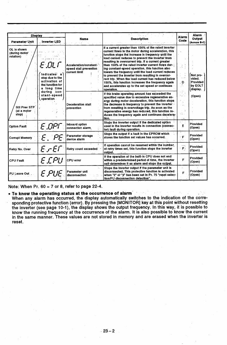
Disl
'
Retry count exceeded -
CPU error
Parameter unit disconnection -
Parameter Unit
i f operation cannot be resumed within the number, of retry times set, this function stops the inverter .output. .- . - If the operation of the built-in CPU does not end within a predetermined period of time, the inverter self-determines it as alarm and stops the output. Stops the Inverter output if the parameter unit is disconnected. This protective function is activated when '2' or '3' has been set in Pr. 75 "reset seie? tion/PU disconnection detection'.
I
Option Fault
Corrupt Memory
Retry No. Over
CPU Fault
PU Leave Out .
lay
- Inverter LED , G -
( indicates*s a stop due to the activation of the function for a long time during con- s tan t-speed
{operation
I
1
Name
Acceleration/constant- ' speed stall prevention . current limit i
1 ,
Deceleration stall prevention
Description
If a current greater than 150% of the rated inverter current flows in the motor during acceleration. this function stops the increase in frequency until the load current reduces to prevent the inwerter from resulting _in overcurrent trip. If a current greater than 150% of the rated inverter current flows dur- f ing constant-speed operation, this function also lowers the-frequency until the load current-reduces to prevent the inverter from resuitingh overcur- rent trip. -When the load current has reduced below 150%. this function increases the frequency again and accelerates up to the set speed or continues ope rat ion. If the brake operating amount has exceeded the specified value due to excessive regenerative en- ergy during motor deceleration, this function stops the decrease in frequency to prevent the inverter from resulting In overvoltage trip. As soon as the regenerative energy has reduced, this function re-. duces the frequency again and Continues deceler?
inboard option connection alarmi
Stops the Inverter output if the dedicated option :
used in the inverter results In connection (connec- tor) fault during operation.
_ _ _ _ ~
Stops the output if a fault in the EPROM which stores the function set values has occurred.
I
Parameter device alarm
Note: When Pr. 60 = 7 or 8, refer to page 22-4.
Alarm .
output ;Across B-C)
'Not pro- vided. Provided 'by EOLT ldisp I ay . (Open)
Provided (Open)
(Open)
Provided (Open)
(Open)
Provided
Provided
- Provided (Open) .
- 23-2
To know the operating status at the occurrence of alarm- When any alarm has occurred, the display automatically switches to the indication of the corre- sponding protective function (error). By pressing the [MONITOR] key at this point without resetting the inverter (see page 10-I), the display shows the output frequency. In this way, it is possible to know the running frequency at the occurrence of the alarm. It is also possible to know the current in the same manner. These values are not stored in memory and are erased when the inverter is reset.

. 1-
5.1.2 Digital and Actual Characters
The alphanumeric characters and actual characters given in the display examples of this manual. .
Actual Digital
. .
Actual Digital Actual Digital
8 Q El R Q 8- El - - Q Q
" ? .-
_I
- .
5.1.3 Alarm History (History of Alarm Definitions) -
Up to eight most recent alarms (alarm definitions) are stored in memory. To check these, use the help function. For more information, see "5 ALARM HISTORY" on page 7-13.
5.1.4 Erasing the Alarm History (History of Alarm Definitions)
To erase the alarm history (history of alarm definitions), use the help function. For- more information. For more information, see "6 ALARM HISTORY CLEAR" on page 7-13.
0
23-3

5.1.5 Alarm Code Output
By setting Pr. 76 (alarm code output selection), an alarm definition can be output-as a 4-bit digital signal. This signal is output from the open collector output terminals equipped as standard on the inverter. Correlation between alarm definitions and alarm codes are as follows. In the table, "0" indicates that the output transistor is off and "I" on (common terminal: SE).
Alarm Definition (Protective Function)
Normal operation IDuring acceleration
- . . .
Inverter .. Output Terminal Signal On/Off Alarm LED Display su I PF OL FU Code
- 0 0 0 0 0 E.OC1 0 0 0 1 ' 1
Output side ground fauWovercurrent External thermal relay operation
E. GF 1 0 1 1 6 E.OHT 1 1 0 0 C
Stall-activated stop Inboard option alarm Parameter storage device alarm Retry count exceeded CPU error Parameter unit disconnection
- .
E.OLT 1 1 0 1 D E.OPT 1 1 1 ' 0 E E. PE
E.CPU -
E.PUE
E.RET 1 1 1 1 F
23-4

5.2 TROUBLESHOOTING
,Sudden load change? - - - .
has failed, a part has been damaged, or any other fault has
- _ _ .The display of the parameter unit is switched as follows to indicate the cause of a faulty operation.
Motor Overload
Inv. Overload
. Cause of Fault Dlsplay _ _ ParameteiUnit I Inverter LED
I
- - .- THM: Overload alarm Thermal relay for motor Reduce load, .
THT :Overload alarm Thermal relay for inverter capacities. Motor used under overload? Increase motor and inverter
. . . - *
acceleration
Inst. Pwr. ~ o s s
Under Voltage
Br. Cct. Fault
Ground Fault
OH Fault
constant speed Main circuit device overheat I Stedy Spd oc OC2 : Overcurrent during I
Check the cause of instantaneous power failure.
IpF :Instantaneous power failure
UVT : Undervoltage
BE :Power return circuit alarm
GF :Ground fault overcurrent circuit. fault.
OHT: ~ ~ ~ r ~ ~ ~ ~ ~ ' External thermal relay operated. Check motor for overheat.
Instantaneous power failure
Drop of power supply voltage
Power return circuit alarm
Ground fault occurred in output
Large-capacity motor started? Check power system equipment such as power supply capacity. Reduce load GD2. Reduce braking duty.
Remedy ground fault Brea.
Reduce load and frequency of operation.
Braking duty too large?
Check motor and cables for ground
- - - _
deceleration
Stll Prev sTp
1 Checkpoint
Reduce load. Increase motor and inverter capacities.
Motor used under overload? OLT :Stall prevention Stall prevention or current limit function activated too long.
Acceleration too fast? Check for output short circuit or ground fault. - t .
Check for cooling fan stop. Sudden load change? - Check for output short circuit or ground fault. Check for cooling fan stop. Deceleration too fast? Check for output short circuit or ground fault. Check for cooling fan stop. Mechanical brake of motor operate I
toofast? _- _ _ -
Acceleration too fast? - _-
Option Fault
Corrupt Memry
Retry No. Over
CPU Fault
pu Leave out
Securely connect. OPT: Inboard option connection alarm* improperly.
PE :Parameter storage device alarm
RET :Retry count exceeded Operation within the number could not of be ret resumed times set.
CPU: CPU error CPU malfunction Change inverter. PUE : Parameter unit The PU has been disconnected from
Option and inverter connected
Storage device (EEPROM) faulty.
Check for loose connector.
k:yr Of parameter write times too Change inverter.
Check cause of alarm occurrence.
Check that the PU is connected Securely install the pu. disconnection the connector. securely.
-.. - _
Deceleration too fast?
*Check for miswiring to reset
*Check for loose connector. terminal.
Remedy 8 .
*Turn the reset signal off. *Securely connect. *Change inverter.
Increase acceleration time. Change fan. Remove obstacle to cooling fan. (Note)
pu to Inverter comms. Error Inv* Reset ON
Keep load stable. Change fan. Remove obstacle to cooling fan. (Note)
*Loose connection between PU and
*Communication circuit fault 0.00 (LED display OK) inverter*l
Err. (LED displav fault)
Increase deceleration time. Change fan. Remove obstacle to cooling fan. (Note) Check brake operation.
Increase acceleration time.
Keep load stable.
Increase deceleration time; (Set deceleration time which matches load GD2.)- - -
I I *Reset signal ON
.~ , I Fr-A' I CPU malfunction *2 - *Switch power off, then on. *Switch reset signal on, then off. *Change inverter.
Note:This alarm does not occur if the cooling fan stops, but it will occur to prevent the main circuit
*l : The parameter unit display remains unchanged but operation may be performed in the external
*2: If the alarm is kept displayed on the parameter unit LCD and unit LED after remedy, the internal
*: When Pr. 60 = 7 or 8, refer to page 22-2.
devices from overheating by the fan failure.
operation mode.
circuit may be faulty. Consult your sales representative.
. 24-1

5.2.2 Faults and Check Points
Fault
blotor does not 'otate.
\
... . .
Motor rotates in wposite direction.
Speed greatly differs from the set value.
Accele ration/decel - Bration is not smooth. Motor current is large.
Speed does not increase.
Speed vanes durins operation.
"PU to inverter-?. comms. error" is displayed on the PU screen.
Typical Check Point *
1) Checking the main circuit Check that a proper power supply voltage is applied (inverter LED display is lit). Check that the motor is connected properly.
0 Check that the start signal is present. -Check that both the forward and reverse rotation start signals are not present simultaneously. Check that the frequency setting signal ismot zero. Check that the signal across terminals AU-SD is on-when the frequency setting signal is 4 tc 20mA. ' . . Check that the output stop signal (across terminals MRS-SD) or reset signal.(across RES
-. -*
2) Checking the input signals " . * . . . . -
I - - T
- - I. '
isnoton. ' . . ' - _ - 3) Checking the parameter set values - '
Check that the reverse rotation prevention (Pr. 78) is not set. Check that the operation mode (Pr. 79) setting is correct.
0 Check that the starting frequency<(Pr. 13) set value is not greater than the nrnning frequency. Check that various operational functions .(such as three-speed operation), especially the
e Check that the bias a-nd gain (Pr. 902- to Pr. 905) settings are correct.. . -
maximum frequency, are not zero. . . - . 4) Checking the load ,
5) Others i
.-Check that the load-is not too heavy and the shaft is not locked. . . -- I
0 Check that'alarm code (such as E.OC1) is not-displaved on the inverter LED. Check that the phase sequence of the output terminals U, V and W is correct. Check that the stah signals (fornard rotation, reverse rotation) are connecte'd properly. Check that the frequency setting signal is OK. (Measure the input signal level.) Check that the following parameter set values are OK: Maximum frequency (Pr. l),-minimum frequency (Pr. 2), bias, gain (Pr. 902 to Pr. 905), base frequency voltage (Pr. 19) , . Check that the input signal lines are not affected by external noise. (Use of shielded cables) Check that the acceleratioddeceleration time set value is not too'short. Check that the load is not too heavy. Check that the torque boost set value is not too large to activate the Check that the load is not too heavy. Check that the toque boost (manual) set value is not too large.
Check that the load is not too heavy. Check that the torque boost set value is not too large to activate the current limit function.
.
- - - I - - . - _ _ _ _ _
, i. -
rent limit fukctiin. .
Check that the maximum frequency set-value is OK, Le. it is not too small. - - - --- '
, - 1
- ,. 1) Inspection of load
0 Check that the load is not varying. i
2) Inspection of input signal . - I "
0 Check that the frequency setting signal is not varying. - - I -
3) Others 0 Check that the settings of the applied motor capacity (Pr. 80) and the number of applied mot0
poles (Pr. 81) are correct for the inverter capacity, and motor capacity in' magnetic flux vecto control.
0 Checkjfiat the-wiring length is with;n 30m in magnetic flux vector control. - - 0 Check that the wiring length is OK in V/F control. . - ,-
Remedy: Change the setting of4special parameter 97 (Td compensation) to 0.- * . - This parameter is-displayed only when 801 is set in Pr. 77. . - - - ~
Note: Parameters Pr. 82 to 99, which are also displayed simultaneously when 801 is set in Pr. 77, must not be set to protect the inveher from damage.
1 Check that the reset signal (terminals RES-SD), is not ON. 1 Check thatthe PU is connected securely.
I
3 ,. 2 . . .
1 1 . - 8 -
c , - . . - .- . - _- _ _ :,
, . . - . - ~ . . , ~ - . : - < . . . ,.. ,
, . -. ' -Note: Prr indicates -a- parameter. - - . -.- . ' . .
$ 3 . . 'r < .
' * .., .- * . ,
, . T ' - * ,
. , f : . . + . , .." , , 7: , . - , ' 2.
. ; . , .
, . I . . + . I _ . _ . . . . .. .
- . I , . . . . . ,
, . . . . _ . .
-. . _ . .L . . ._ . .
- - . . - . .. .
. - . , .-. . .
- . . - . . . i .
- . . " - 1- . -. ~ . . . . . . . :.- . ,

I Note: For the definitions of the alarm'codes, see page 24-1.
If a current greater than 150% of the rated Inverter current flows in the motor during acceleration, this function stops the increase in frequency until the load current reduces to prevent the inverter from resulting In overcurrent trip. If a cur- rent greater than 150% of the rated Inverter current flows during steady (constant-speed) operation, this function also lowers the frequency until the load current reduces to pre- vent the Inverter from resulting in overcurrent trip. When the load current has reduced below 150%. this function In- creases the frequency agaln and accelerates up to the set speed and continues operation. If the brake operating amount has exceeded the specified value due to excessive regenerative energy during motor deceleration, thls function stops the decrease In frequency to prevent the inverter from resulting in overvoltage trip. As soon as the regenerative energy has reduced, this function reduces the frequency again and continues deceleration.
During accel- eration During constant speed During decel- erat ion During accel- .
If the converter output voltage Is excessive due to ,eration Ithe regenerative energy from the motor, the protec- During tive circuit is activated to stop the transistor out- constant put. This may also be activated by a surge voltage speed
During generated in the power supply system. decel-
If the inverter output current reaches or exceeds 200% of the rated current, the protective clrcult is activated to stop the Inverter. When any main clr- cult device is overheated, the PrOtectIVe ClrCUit is also activated to stop the Inverter.
I
I
power failure protection
Undervoltage protection
Power return circuit alarm detection
Overload shut-
overcurrent protection)
(electronic
output side ground fault overcurrent protect,on
If an Instantaneous power failure has occurred In excess of 15msec (this applies also to inverter Input power shut-off), this function Is activated to stop the Inverter output In order to prevent misoperation. At this time, the alarm output con- tacts are open (across B-C). (If the power failure Is within 15msec. the control circuit operates without fault. If the power failure persists for more than about lOOmsec, the pro- tective circuit is reset.) If the inverter power supply voltage has dropped, the control circuit cannot operate properly, resulting in the decrease in motor torque and/or the increase In heat generation. To pre- vent this, if the power supply voltage drops below about 150V (300V for the 400V series), this function stops the in- verter output. When the power return circuit Is faulty or the regenerative electronic thermal relay or other error has occurred, this error display is output and the Inverter output is stopped. The electronic overcurrent protection In the inverter detects inverter overload or motor overheat and activates the protec- Motor tive circuit to stop the inverter output. When a multi-pole Overload motor or more than one motor is driven, for example, the motor(s) cannot be protected by the electronic overcurrent protection. Provide a thermal relay in the Inverter output cir- cuit. In this case, Setting the electronic Overcurrent PrOteC- tion value to OA activates the inverter protection only. (Activated at a current 150% or more of the rated current.) i f a ground fault current has flown due to a ground fault oc- curring In the output (load) side of the inverter, this function stops the inverter output. A ground fault occurring at low ground resistance may activate the overcurrent protec-tion (OCl to OC3).
Inst' Pwr'
Under Voltage
Br. Cct. Fault
Inv. Overload
Ground Fault
5.2.3 Protective Functions
When any of the protective functions has been activated, switch the power off, then on, or reset the inverter with the reset terminal (RES). (Inverter reset can also be executed in the PU help menu.)
- Alarm Code Function I Description w Parameter
play
Inverter LED Alarm Output
Acceleration Iconstant- speed stall prevention current limit
OL is shown durlng motor rotation. Jot provided.
'rovided by EOLT display.
(OLT) indicaes a stop due to the activatlon of the function for a long time during constant- speed operation.
D Stii Prev STP is shown at a motor stop.
Deceleration stall preven- tion
OC During ACC 1 - 2
Ove rcu rre nt Shut-Off 'rovided E.OC2 Stedy Spd Oc
E*OC 3 OC During Dec 3
4
-
7
-
8
A
Ov During Acc
Regenerative overvoltage Shut-Off
) rovided EwOu 2- Stedy Spd Ov
Ov During Dec
€.I -ff Vovided
Vovlded.
~
E. bE (BE)
Motor protection
Emr ~n TTHM)
protection . Inverter
€.r Nr Urn)
'rovided
- -
'rovlded
'rovided
24-3

Inboard Option connection alarm
Stops the inverter output if the dedicated option used In the Option Fault €.Of r (OPT) inverter results in connection (connector) fault. (Note) E
F
F
Provided
Provlded .
Provided
Parameter storage device alarm
Stops the output if a fault in the EEPROM which stores the Corrupt . . Em f parameter set values has occurred. . Memry , (PE)
Retry count exceeded
If operation cannot be resumed within the number of retry times set, this function stops the inverter output. Retry No. Over E,r E
(RET)
. F Provided _ - I f the operation of the built-in CPU does not end wlthin a pre- determined period of time, the inverter self-determines It as alarm and stops the output. Stops the inverter output if the parameter unit is discon- nected. This protective function is activated only when '2' or "3" has been set in Pr. 75 'reset selection/PU disconnection detection' function.
E.Cf u €.f UE
CPU Fault (CPU)
pu Leave Out (PUE) .
F Provided
tz:r -Alarm Output I Display
pari~:t*r - I Inverter LE6 Functlon Description
I
If the external thermal relay for.motor overheat protection or the.internally mounted temperature relay in the motor has been switched on (relay contacts open), this function stops the inverter output and keeps it stopped. This protection is only provided when '1' or '3' has been set in Pr. 17 'exter-
External thermal relay ope rat ion
OH Fault
CPU error
Parameter unit disconnec- tion
// *: The stall prevention operation current can be set as needed. The factory setting is 150%.
Note: When Pr. 60 = 7 or 8, refer to page 22-2.
. .
. . . .
I . _
. . . , . . . ,
. . . - . . - .~
. .
24-4

5.3 MAINTENANCE AND INSPECTION
. -
ring due to adverse influence by the installation environment, such as tem- perature, humidity, dust, dirt and vibration, changes in the partsewith time,
5.3.2 Checkitems '
1 - 1
I - * . - (1) Daily inspections . . - .'Check the following: - -
- . - - . . - _ - - - - . - _ _ -
I
(1) Motor operation . -
(3) Cooling system 1 "
(4) Vibration and noise - - a -
' . (2) Installation environment 4 - ~.
(5) Overheating and discoloration During operation, check the inverter input voltage using a tester.
- (2) Periodic maintenance and inspection
Check the areas inaccessible during operation and requiring period inspection. (1) Cooling system ....................................... Clean the air filter, etc.
retighten as necessary. (2) Screws and bolts .................................... Check that they are securely tightened and
(3) Conductors and insulating materials ......... Check for corrosion and damage. (4) Insulation resistance ............................... Measure. (5) Cooling fan, smoothing capacitor, relay .... Check and change if necessary.
Note: Have a proper understanding of the definitions of power and alarm indications provided for the transistorized inverter. Also, have a understanding of the settings of electronic overcur- rent protection, etc. and record proper set values. (Enter the values into the Customer Set Value section of the "Parameter List" on page 9-1.)
See the next page for the Inspection List.
- (3) Insulation resistance test using megger
(1) Before performing the insulation resistance test using a megger on the external circuit, disconnect the cables from all terminals of the inverter so that the test voltage is not applied to the inverter.
(2) For the continuity test of the control circuit, use a tester (high resistance range) and do not use the megger or buzzer.
(3) For the inverter, conduct the insulation resis- tance test on the main circuit only as shown on the right and do not perform the test on the control circuit. (Use a 500VDC megger.)
Ground terminal
25-1

Daily and Periodic Inspection
Inspection Item
i - I Interval c Area of
Inspection
ieneral .. -
Method: Crlterlon -F Ddlc 2 years I I
i . - .. I Ambient temperature:
Thermometer, hygrometer, recorder
-1 0% to +soot, non-freezing.
Ambient humidity: 90% or less,
See note on page 3-1. Check ambient temperature, humidity, dust, dirt, etc.
Surrounding environment
. -
Overall. unit
Power sup- ply voltage
non-condensing. - : - .". - Viqual and auditory checks. No fault. Check for unusual vibration
and noise. . I
Check that'main circuit ' voltage is normal. * '
170 to242V . ' - Tester, digital. (323 to S06V) 50Hz
multimeter 170 to 253V (323 to SOSV) 60Hz
Measure voltage across inverter terminals R-ST. - . .
(1) Disconnect all cables (1) SMn or more. I - -
from inverter and mea- (2), (3) No fault. sure across terminals R, I .
(1) Check with megger (across main circuit terminals and ground terminal). ,
and bolts.
each part.
(2) Check for loose screws
(3) Check for overheat on
(4) Clean. (1) Check conductorsfor
distortion. (2) Check cable-sheaths for
breakage.
Check for damage.
0
' 5
, . -
tlain circuit
, - ~ . - *
General
_ .
I S, T, U, V,' W and ground terminal with megger.
(2) Retighten.
SOOVDC class megger I
. I - - I (3) Visual check.
( l ) , (2) Visual check. (1). (2) No fault.
. .
- _ Visual check No fault
(1), (2) Visual check. (1). (2) No fault. (3) Measure with capacity (3) 85% or more of rated
meter. ~ capacity. Capacity meter
- . (1) Auditory check. (1) No fault. (2) Visual check:. - (2) No fault.
. _
Conductors, cables. ~
Terminal block
Smoothing capacitor - . ,
(1) Check for liquid leakage. (2) Check for safety valve
projection and bulge. (3) Measure electrostatic
capacity. (1) ~ Checkfor chatter during
operation. (2) Check for rough surface
on contacts.
(1) Check for crack in resis- tor insulation.
(2) Check for open cable. - . - -
Relay .
Resistor
(1) Visual check. Cement re- sistor, wire-wound resis- tor.
(2) Disconnect one end and measure with tester.
(1) Measure voltage across inverter ou!put terminals I u-v-w.
(2) Simulatiiely connect or disconnect inverter protective circuit output terminals.
I (1) Phase-to-phase voltage balance within 4V (8V) for
(1) No fault. (2) Error should be within . Tester,
~f 10% of indicated resis- tance value.
digital multimeter
, -
Zontrol :ircuit Votective :ircuit
(1) Check balance of output, voltages across phaqes with inverter operated independently.
(2) Perform sequence protec tive operation test to make sure of no fault in protective and display cir cuits.
(1) Check for unusual vibra- tion and noise. - - I '
(2) Check for loose connec- tion.
(1), Check for LED lamp - - blown.-.- _-_ .-
(2) Clean.
Check that reading is normal - -
. -
Operation check of sequence. rectifier type
I lvoltmeter
. * I - -
Cooling fan ---I
Zooling- system
-_
Xsplay
(2) Retighten.
. - > - - . . lamps on panel. (2) Clean with iag.
ammeter, etc. t Meter
General
(1) Check for unusual vibra-
(2) Check for unusual odor. tion and noise. checks.
due to overheat, damage, (2) Check for unusual odor
blotor
Insulation resistance
Check with megger (across terminals and ground termi- nal).
Disconnect cables from U, V, W, including motor cables. I 5Mn or more. 0
Note: The value for the 400V series is indicated in the parentheses.

L
PartName ’ Standard Replacement Interval Description Change (as required)
Change the board (as required). - * Change (as required) -
Cooling fan Smoothing capacitor in main circuit Smoothing capacitor on control board Relays
2 to 3 years 5 years 5 years
- . _ Change as required. -- - -

,
i
b
D
5.3.4 Measurement of Main Circuit Voltages, Currents and Powers
Measurement of voltages and currents -Since the voltages and currents on the inverter power-supply and output sides include harmonics, accurate measurement depends on the instruments used and circuits measured. When instruments for commercial frequency are used for measurement, measure the following circuits using the instruments given on the next page.
- ~ - _ - - . - - - _ . - *
. - . r
- .
3-phas power supply
Output voltage
Output current
. -
i
Typical Measuring Points and Instruments
‘25 -4

. - I Measuring+Points and Instruments I - - . - -
,cross u-v, v-w and w-u
Power supply voltage VI
Power supply side power PI
Rectifier type AC voltmeter (Note 1) (Not moving-iron’type) 1% of maximum output voltage: .
Difference between phases is within f
Power su.pply side power I factor Pfi
i t U, V and W, and across U-V ind V-W-
Output side current 12
Electrodynamic type single- ~ ~ w ~ ~ ~ ~ & ~ ~ t h o d c p r 3-wattmeter phase wattmeter method)
Output side power.P2 I Output side power factor Pf2 I . .
Frequency setting signal I Frequency setting power supply
Frequency meter signal
. .
Alarm signal
Measuring Point
rcross-R-’S, S-T and T-R
I , S and T line currents rt R , S and T, and across R-S, i-T and T-R ;alculate after measuring pows
~ f , P P 1 - X 1 0 0 % d3vl* 11
* Remarks Reference Measured Value) Measuring Instrument.
Moving-Iron type AC voltmeter * -
Moving-iron type AC ammeter Electrodynamic type singie-
Commercial power supply 170 to 242V (342 to 506V) 50HZ 1170 to 253V (342 to 506V) 60Hz .
I P 1=w 1 1 +w12+ w 13
bhase wattmeter I (3-wattmeter method) supply voltage, power supply side current and power supply side power.
I , ICurrent should be eaual to or less than rated Inverter curreni.
J, V and W line currents ~Movlng-lron type ammeter ,lDifference between phases is 10% or , I I I lower.
2aiculate In similar manner to power supply side power factor.
4cross 2(+)-5 4cross 1 (+)-5 4cross 4(+)-5 4cross 1 O(+)-5 4cross 1 OE(+)-5
Moving-coil type (Tester, etc. may be used) (Internal resistance: 50kn or larger)
4cross FM(+)-SD
4
Gcross AM(+):5. - f
Across STF, STR, RH, RM,
Across RES(+)-SD Across MRS(+)-SD
RL. JOGIOH, RT, AU-SD
Across A-C Across B-C
Moving-colitype (such as tester),’
Note 1 : Accurate data will not be obtained by a tester. * Values in parentheses indicate those for 400V series.
I to 5VlO to 10VDC I to f 5VlO to f lOVDC 1 to 20mADC
I OVDC ipprox. ~ V D C at maximum fre- (uency (without frequency meter)
T1
Pulse width T1: Adjusted by Pr.900 Pulse cycle T2: Set by Pr.55
(Valid for frequency monitoring onty)
4pprox. 10VDC at maximum fre- iuency (without frequency meter)
!O to 3OVDC when open. 3N voltage: 1V or less
Zontinuity check CNormab <Fault>
4cross A-C: Discontinuity Continuity 4cross B-C: Continutty Discontinuity
- ‘ I
. .

... ?,; ,--;.-> . I . . . > '
. . . . . * , 2." .... ; : I ' . , . .- ,:. n-., . ' . . . . . . ,i . ' . . . . . . . . .
. . . . n . . . '
L . . . . . . . / . " . . . . < . . - 9 . - I * , , , I
,- ... . . 'I
..... > . .,.*". . ..*'.Y * * ! - , ; . * , - !.. . . . ' I ~ . 4 >I ' \ a
' . This chapter provides detailed information"ab0ut' " ""peripheral selection instructions" for 'the FR-'A201 E
Always read the precautions and instructions in this
I t .
. I *.:
"inverter with built-in power return function". . ,
- . '..*. . . . . . . s-..., .. ! .. , , \ . , . - . , * : . 1 I . .* .
-I -chapter before using the equipment. . . . . . . . . . . . . . . . . . . . . . , -
a s . . - ,, . '. ' I < , * , . L.L . I .,
, . : I. ._
. . . . . . . 1 .. , , * A > . - , - . , . I
. : i .. F .. i ;, I , ...... I I t . . . ;; . . . . . . . . . . . . ,. ,. . , . * . * ' , I . , t ' ;..* . . --. > ' . ' ' , '
I 'I . , L * < Y , . 1. * < - . . . - . . \ L , I I *
. . . . . ... * , _ . ' ...... -. . I . , , . * < . - 4 . . - . I . # . I I , . i I
. l i
" . . - , I .I
. r r . \ .: . -.. A. ' . 9 . "'1 ' . . . . . * : I . . . I
. . . , < . ,
. . . - .1
6.1 INSTRUCTION$ FOR SELECTING PE'RIPHERALS ......... 26 - 1 . I . r , . I I .
s.

6.1
tend to increase. Because of its operation principle, the inverter generates noises and may affect adjacent devices. The following noise reduction meas- ures can be taken according to the place of installation, select peripheral
INSTRUCTIONS FOR SELECTING THE PERIPHERALS
. Air-propagated Noise directly radi- noise I ated by inverter
. Noise radiated by power cables
Noise radiated by motor cables
r 5
.......Path , Path 2)
Path 3)
.......
....... Magnetic induction noise 1
Static induction 9
26-1
.......Path 4),
Path 6) .......

3 1 .:
Noise Path
. 7 )
. 4-33 Telephone
I . M eas u res When devices which handle low-level signals and are susceptible to malfunction due to noise (such as nstruments, receivers and sensors) are installed near the inverter and their signal cables are contained in the same panel as the inverter or are run near the inverter, the devices may malfunction due to air-propagated qoise and the following measures must be taken: (1) Install easily affected d-evices away from the inverter. (2) Run easily affected signal cables as far away as possible from the inverter. (3) Do not run the signal cables and power cables (inverter I/O cables) in parallel with each other and do
(4) Insert line noise filters into supply and motor cables, and radio noise filters into supply to reduce cable
(5) Use shielded cables for signal and power cables and run them in individual metal conduits to produce
When the signal cables are run in parallel with or bundled with the power cables, magnetic and static induction noises may be propagated to the signal cables and malfunction devices, the following measures must be taken: (1) Install easily affected devices as far away as possible from the inverter. (2) Run easily affected signal cables as far away as possible from the inverter. (3) If the signal cables and power cables (inverter I/O cables) run in parallel with each other do not bundle
(4) Use shielded cables for signal and power cables and run them in individual metal conduits to produce
When the power supplies of the peripheral devices are connected to the same power supply as the inverter, inverter-generated noise may flow back through the power supply cables and affect the devices, the following measures must be taken:- (1) Install the radio noise filter (FR-BIF) to the supply cables (I/O cables) of the inverter. (2) Install the line noise filter (FR-BLF, FR-BSFO1) to the supply and motor cables of the inverter. When a closed loop circuit is formed by connecting the peripheral device wiring to the inverter, leakage current may flow through the ground cable of the inverter and affect the device. In such a case, disconnection of the ground cable of the device may cause the device to operate properly.
,.
not bundle them.
radiated noise.
further effects.
them, keep parallel distance as short as possible.
further effects.
26-2

Data example
I -
Conditions Motor: 0.75kW Average terminal voltage (OdB=lpV, 12OdB=lV)
_ .
FR-Z240-7.5K &--a FR-A240-6.5K. fC E
QFR-A241E6.5K. t c a i k H ~ -
2kHZ
. . c.. .': .
0
0.1 0.2 0.4 0.6 0.8 I 2 6 8 I O ' 20 30 I
- .. Frequency(MH2) * - '
. inverter Transmission interference Comparison - . (Quasi-peak values)
1 I I I I - 1
-40 I- no-load operation 2 - _ . _ - .
30' - -. 0 30 60 90 120
Noise frequency (MHz)
Relation between Carrier Frequency and Motor Noise
. .
Conditions FR-A221E-5.5K (Carrier frequency 14.5kHr) Average terminal voltage (OdB=l pV, 12OdB=lV)
FR-A24i E-6.5K n (co t4.6kHZ 6-4 ko2kHZ
' * _ _ - -
- I : A - I t
0.1 0.2 0.4 0.6 0.8 1 2 4 6 8 10 20 ' 3 0 . c Frequency (MHz) .
Inverter Transmission interference Comparison -. (Quasi-peak values)
I Conditions ' Inverter: FR-A221E03.7K
' 100' Motor: FR-JR 4P 3.7kW .'Output frequency: 30Hz . ~ Parallel cable Noise form: normal mode
* * i - -+--+--A g - - - W 01
0 w . 2 60
.E 40
= 20 f -0
).
. - _ .
0 IO 20 30 40 50- - Line-to-line distanced
induction Noise to Signal Cables by Inverter Output Cables
- --
(on
* Noise terminal voltage: Represents the magnitude of noise propagated from the inverter to the power supply.
26-3

Example of measures against noises . 1- - .
Item . Frequency
Environment Quantitative grasp
Generated amount
- -
I \-
Install filter (FR-BLF, FR- BSFO1) to inverter input sid
> e 4-0 - .
Inverter power supply I
- Install filter FR-BIF to Use 4-core cable for motor inverter input side. -\ power cable and use one
cable as ground cable. - .
Separate. inverter and pow- line 30cm or more (at least 10cm) from sensor circuit.
Control power +no supply
D? not ground shield but connect It to signal common- cable. Do not ground control box directly.
Do not around control cable.
#-
, _
- , . . Harmonics Noises Normally degrees 40 to or less To line, power impedance To space, distance, wiring path . Theoretical calculation possible. Almost proportional to load caDacitv. switchina meed increases) ~
3kHz High frequency (several 10kHz.to MHz order)
Random occurrence, quantitative grasp difficult. According to current fluctuation value (larger as '
? . 6.1.2 Power-Harmonics . . " . In -- ,
The inverter may generate power harmonics from its converter circuit, affecting .generators, power capacitors, etc. Power harmonics differ from noise and leakage currents in .generation source, frequency band and transmission ,method. Take appropriate' measures according to the following description .
Differences between harmonics and noises are listed below:
" . . - *. 1
I
Specified in the standard of each Different according to manufacturer's equipment specifications. Immunity of equipment affected device
\
37 45 55
66 54 51 80 66 62 100 80 75
26 -,4

Note: The power factor improving capacitor and surge suppressor on the inverter output side may be heated or damaged by the harmonic components of the inverter output. Also, as overcurrent pro- tection will be activated due to overcurrent flow- ing in the inverter, do not install a capacitor and surge suppressor in the inverter output circuit when the motor is driven by the inverter. To improve the power factor, insert a power factor improving reactor in the inverter primary circuit or DC circuit. For more information, refer to the reactor Technical Information.
.-----a
. Power factor Do not insert a improving AC power factor im-
proving capacitor.
* Fig. 5.2 Inverter Power-Factor Improvement 1 .
, I t .
/ ‘ .
6.1.3 Leakage Current - 8
Because of static capacitances existing in the inverter I/O wiring and motor, leakage- current flows through them. Since its value depends on the- static capacitances, carrier frequency, etc., leakage current increases when the low-noise type inverter is used. In this case, take the following measures. 1) To-ground leakage current
Leakage current may flow into not only the inverter’s own line but also the other line
*through the ground cable, etc. This leak- age current may operate earth teakage cir- cuit breakers and earth leakage relays unnecessarily. ’
.----_I ~
e-Measures Decrease the carrier frequency (Pr. 72)
Power supply
circuit breaker --
---e---
Leakage Current Sneak Path
Of the inverter- Note ~- that - motor noise *:_ For information on selecting the earth leakage circuit breaker, . increases.. . see page 176. ~
By using earth-1eakag.e circuit breakers compatible with harmonics and- surges -(e.g. Mitsubishi’s New Super NV series) in the inverter’s own line and other 1ine;operation - - -_ can be
* For the selection of the earth leakage circuit breaker, refer to page 26-7. performed with low noise (with the carrier frequency kept high).
1 i ’ ‘
To-ground leakage current data.example
400 I Conditions , Carrier frequency
Motor...SF-J 3.7kW 4P 14.5kHZ (FR-A241E)
2 k H ~ (FR-A24lE) e 1 kHz (FR-2241)
_ - . - . - - I 1 I e I I . - -
0 50 100 Output side wiring I - - length (m)
. C
-To-Ground Leakage Current versus Carrier Frequency and Wiring Length
. -
~
._- . - -
-
1000 700
500
4 300 - g 200 3
0 -m loo
f 70
50
30
ring length: 20m
5.5 ‘7.5 -. 11 15 18.5 -22 30 37 45 55 - _ _ Motor capacity (kW) - .
To-Ground Leakage Current versus Motor Capacity
26-5

2) Line-to-line leakage current ' Harmonics of the leakage current flowing in the static capacities-between the inverter output cables may operate the external thermal relay unnecessarily. When the wiring length of a 400V class small-capacity model (especially 7.5kW or down) is long (50m or more), the external thermal relay is likely to operate unnecessarily because the ratiqof the leakage current to the rated current of the motor increases.
b
0 Line-to-line 1eakage.current data example (200V class)
Carrier frequency:
w-- - &.#T
The leakage current of the 400V class is twice larger.
NFB Thermal relay
lnvelter , Power supply
Line-to-Line Leakage Current Path
Measures c? Use the electronic overcurrent protection of the inverter., Install a reactor (FR-BOL) in the output side. Decrease the carrier frequency. Note that motor noise increases. - I
To protect the motor from the line-to-line leakage current, it is recommended to use a temperature sensor to directly detect the temperature of the motor;.
' i
1 . . . ? * .
-- . ~-
.- -- - -
* -
_ _ ._ - L - - . ~ - -

c
Leakage current 191
Leakage current Ign
Leakage current 192
6.1.4 Selecting the Rated Sensitivity Current for the Earth Leakage Circuit Breaker
When using the' earth leakage'circuit br-eaker .with the inv c u rr e nt as f o I Io w s :
New Super NV series (Type SF, CF)
0 Conventional NV series (Type CA, CS, SS)
ted Sinsitivity . ' -
' 1eakage)Current Example " Leakage Current Example of Cable Path during Corn- - , of 3-Phase Induction Mo- merclal Power3upply Opr - I tor during Commercial eration When the CV . . Power Supply Operation Cable Is Routed in Metal - e - - ( 2 0 0 ~ 60Hz). - -.
' l
Rated sensitivity current: !An21 Ox(lg1 +lgi+lgm)
Rated sensitivity current: lAnr1 Ox{ Igi +lgn+3x(Ig2+ Conduit (200v 60Hz) f
New Super NV Conventional
5m 1 OOOm
0 (without noise filter) 70m
1000m -
NV
3 3 ~ - = 0.17
3 3 ~ - - 2.31
Igm)) , - .
30 Rated sensitlvlty current (~lgxlo)
. . .. , .
100
, . ' . . .
Note:
igi,ig2 i
Ign* .:
Igm :
<Example>
leakage currents of cable path during commercial power supply operation leakage current of -noise filter on inverter input side - -- ' - - - leakage current of motor during commercial power supply operation
" 2 36 8 14 22 38 80 150 66 30 60 100
2.0
z .E 1.0
g 06
).
2 0.7
Q) m 0 3
Y a 02
A ,
- 0.1
Cable size (mm2) Motor capacity (kW)
1 -
1
* - - . a 1 ' . - .
l . , . . . - . I I - , . 1 , - .
1. The NV should be installed to the power supply Selection Example . .
side of the inverter. (for the diagram shown on the left) (mA) 2. Ground fault in the output side of the inverter
can be detected at the running frequency of 120Hz or lower.
3. In a Y connection neutral point grounded sys- tem, the sensitivity current is higher against ground fault in the inverter output side. Hence, the protective ground resistance of the load equipment should be 1 0 ~ or less.
4. When the breaker is grounded on the output side of the inverter, it may be unnecessarily op- erated by harmonics if the effective value is less than the rating. In this case, note that the eddy current and hysteresis loss increase and temperature rises.
I 0.1 8 I Motor leakage current lam
f3
Total leakage current I I 2.66 ! 7.64 I
For the leakage current value of the noise filter installed on the inverter input side, contact the corresponding filter manufacturer. (For Mitsubishi's dedicated filters, see pages 28-7 and 28-9.)

6.1.5 Peripheral Device List
- 26-8

. .
- , "inverter-driven, dedicated:motor". - - - . _ _ _
(2) Suppressing the micro surge voltage- from the inverter side
6.1.6 Driving the 400V Class Motor by the Inverter
1
f - 1-
m - On the output side of the inverter, connect a filter which suppresses the micro surge voltage to make the terminal voltage of the motor 850V or less. When- the motor is to be driven by Mitsubishi. inverter, connect the optional surge voltage
. suppressing filter (see page 28-10) on the output side of the inverter.
- - '
-
I

. - 7 : r : i . . . .
' I " ' . . I . . A * r
- 1 . " *~ %". * '. ,v: .. , . -
. . . . . . . I .. . . . . . . . . . . . . 1 .. 7.1 SPECIFICATIONS .... .... i,.* .......,...... ........... ,......... ............ i...:..27 -, 1
". _. , . . " .
. .& I . . ' . . . . '~ '';'7. "SPE-CIFICATIONS ,
.This chapter provides detailed information on the "speci- fications" of the Fd-A20l E "inveher with built-in power
' return function". ,,, ,.:
Always read'the precautions - . t .. and instructiongin " . ' this chap- ter before using the equipment.
. . . . . . , . . ...
. . . . : - . 1
,ti' . *.1<; " \ * ......... ..................... ........ 7.2 0 PTI ONS ;:. i......;;...: ;..;........... ..... ........28 1 : - . ,. . ;:,,-; :. - $ ,. !: .I . , , r .
I , . I . : I
I . 1. . . - . . . . .'- . . . . . . . . . . . . . I .: . . . . . . . . . . . . . i . * I . / . . I
" . . * ' .
. ^ . . . ' . I , . 1 . . . . . .r ' .r . ,
. 1 . 2 . . I . ~. .. + I . . . . , . . . . . . .

7.1 SPECIFICATIONS
This section introduces specifications applied to the FR-A201 E series. The inverter must be used in accordance with the following specifications:
Protective structure (JEM 1030) Cooling system Approx. weight (kg)
Voltage '4 Regenerative braking torque Rated Input AC voltage, frequency Permissible AC voltage fluctuation
instantaneous voltage drop immunity
Three phase, 200 to 220V 50HZ,200 to 230V 60Hz 100% continuous, 150% 60 seconds
Three phase, 200 to 220V 50Hz, 200 to 230V 60Hz
170 to 242V 50Hz,170 to 253V 60Hz
Permissible frequency fluctuation f5%
Operation is continued at more than 165V. At less than 165V, operation is continued for 15msec.
Power supply capacity (kVA) '5 12 I 17 I 20 I 28 I 3 4 1 41 I 52 I 66 I 80 I 100
Open type (IPOO) Forced air cooling
24 I 24 I 37 I 37 I 48 I 48 I 63 I 85 I 85 I 120
Protective structure (JEM 1030) Open type (IPOO) Cooling system Forced air cooling Approx. weight (kg) 23 I 23 I 3 4 1 37 I 52 I 52 I 63 1 85 I 87 I 120
kW (HP) rating 5.5 to 37 (7.5 to 50)
45, 55 (60, 75) 5.000 10.000
27-1

" - . . , I
. . Common Specifications - -, 1
;ontrot system Control specifications High carrier frequency sine-wave PWM control (V/F control or magnetic flux vector control can be selected) . .
3utput frequency range 10.2 to 400Hz / , .
=requency accuracy
,,oltage/frequency characteristic - -
=requency setting - *esolution
Within fO.2% of maximum output frequency (25°C~100C)/analog input, within 0.01% of set output frequency/digltal input Base frequency set as required between 0 and 40OHz. Constant torque or variable torque pattern can be selected. -
0.015Hz/60Hz (terminal 2 input: 12 bits/O to lOV, 1 lbits/O to 5V, terminal 1 input: 12 bits/-10 to Analog input I +1OV, 11 bits/-5 to +5V) I - .
Starting torque
4cceleratiorVdeceieration time petting DC dynamic brake % - Stall prevention operation level Frequency Analog input. setting signal Digital input
rorque boost
_ - Digital input . I0.002Hz/60Hz (0.OlHz when PU is used)
150%/1 Hz (for magnetic flux vector-control) *
0 to 3600 seconds (acceleration and deceleration can be set Individually), linear or S-pattern accel- eration/deceleration mode can be selected. Operation frequency (0 to 120Hz), operation time (0 to 10 seconds), voltage (0 to 30%) variable Current limit can be set (0 to 200% variable), presence or absence can be selected. 0 to 5VDC, 0 to lOVDC, 0 to f SVDC, 0 to klOVDC, 4 to 20mA BCD 3-digit or 12-bit blnary using parameter unit (when the FR-EPA or FR-EPE option is used)
Manual and automatic torque boost - '
Provided w ih jogging (JOG) mode select terminal '7 Input of frequency setting signal 4 to 20mADC (terminal 4) is selected. Shut-off of inverter output (frequency, voltage) Alarm retained at the activation of protective function is reset. Maximum/minimum frequency setting, frequency jump operation, external thermal relay input selec- tion, polarity reversible operation, automatic restart operation after instantaneous power failure, com- mercial power supply-inverter switch-over operation, forwardheverse rotation prevention, slip compensation, operation mode selection, auto tuning function. 4 types can be selected from inverter runnlng, up to frequency, instantaneous power failure (undewoltage), frequency detection, second frequency detection, during program mode operation, during PU operation, overload alarm, regenerative brake pre-alarm, and electronic overcurrent protector pre-alarm. Open collector output. Contact output ... change-over contact (23OVAC 0.3A. 3OVDC 0.3A) Open collector. ..alarm code (4 bit) output 1 type can be selected from output frequency, motor current (steady or peak value), output voltage, frequency set value, running speed, motor torque, converter output voltage (steady or peak value), regenerative brake duty, electronic overcurrent protector load factor, input power, output power, load meter, and motor exciting current. Pulse train output (1440Hz/full scale) or analog output (0 to
Operating statu
Alarm definition Operating status
Alarm
Start signal I Foward and reverse rotations individual, start signal self-holding input (8wire input) can be selected
1 OVDC). Selection can be made from output frequency, motor current (steady or peak value), output voltage, frequency set value, running speed, motor torque, overload, converter output voltage (steady or peak value), electronic overcurrent protector load factor, input power, output power, load meter, motor exciting current, cumulative operation time, regenerative brake duty. Alarm definition is displayed when protective function is activated. 8 alarm definitions are stored. State of input terminal signal, state of output terminal signal Output voltage/current/f requencynnput terminal state immediately before protective function is acti- vated
Up t0.7 speeds can be selected. (Each speed can be set between 0 and;400Hz, 'running speed can be changed during operation from the parameter unit.) Multi-speed selection
interactive guidance
Second acceleration/decelerat ion time selection
Operation guide, troubleshooting and graphic display by help function
Overcurrent shut-off (during acceleration. deceleration. constant speed), regenerative overvoltage
Jogging operation selection Current input selection output stop Alarm reset
Operation functions
Operating status
Alarm (inverter trip)
For meter
Display on parameter unit or inverter LED
Additional display to parameter unit only
0 to 3600 seconds (acceleration and deceleration can be set individually.) - '
shut-off, undewoltage, instktaneous power failure, overload shutloff (electronic overcurrent protec- tion), power return circuit alarm *8, ground fault current '9, output short circuit, main circuit device overheat, stall prevention, overload alarm.
Protective/alarm functions
-10°C to +50°C (non-freezing). 90%RH or less (non-condensing) -20°C to +65"C Indoors. No corrosive gases, flammable gas, oil mist, dust and dirt. Below 1000m, 5.9m/s2 (0.6G) or less (conforms to JIS C 0911)

Note: *I The applicable motor capacity indicated is the maximum applicable capacity when the . Mitsubishi 4-pole standard motor is used.
- *2 The rated capacity indicated assumes that the output voltage is 220V for the 200V ’ ‘
- - *3 The % value of the overload current rating indicates a ratio to the rated output current of the-inverter. For-repeated use, it is necessary to wait until the inverter and-motor- return-to temperature below the value at 100% load.
*4 The maximum output-voltage-does not exceed the power supply voltage-. Below the power supply voltage, the maximum output voltage can be set as required. ‘ ‘ . ’ _ - - - -
*5 Where a power-supply is 342V and below or 484V and-above for the 400V class _ - inverters, change the position of the jumper to the internal transformer, according to7‘-
page 3-7. *6 The power supply capacity depends on the value of. impedance on the power -supply. ---.
side (including the input reactor and cables). .: _ - *7 Jogging operation can also be performed from the parameter unit. -
*8 When the power return-circuit alarm or regenerative electronic thermal relay error occurs, the brake transistor’alarm (BE error) is displayed. , _ - -
series and 440V for the 400V series. - . - - -
-
- - .
. .
. . . - -
-
- _ - -
*9 May not be protected depending-on the ground fault mode; 1 . - -_
* I O Temperature applicable for a, shot period in transit, etc. ,. - .- - - _ - - ~ - . - _ -
i - . . -- .. - . - _ - _ . __ . _ . _ _ - _ ~ _ _ A .
. * - -- - .* . - - - _ _ - -__
*_I - ~ _ _ - - _ .
+.. 1
~~ * . - . - ..
<. I
- - - - - _ _ - _ - -. . .
- _ _ _ - -___ - - . _ _ , -
- _
- - - - I-- ” - __I. __ - - ~I-
t , . .
. . . . . . . . . . . . , 4 -~ - - - -
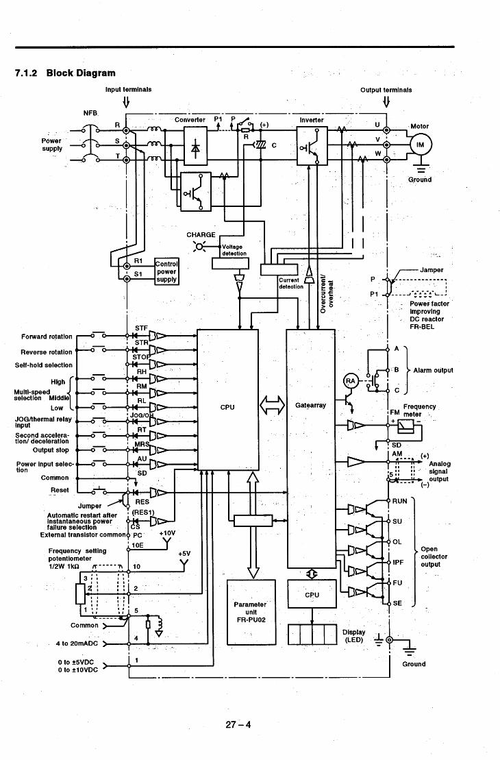
7.1.2 Block Diagram 1
. . i .
I
CHARGE ,-I I I
u J
DC reactor FR-BEL
Forward rotation
Reverse rotation
Self-hold selection
selection Middle Multi-speed
JOGAhermal relay input Second accelera- tion/ deceleration
Low High{
output stop
Power input selec- tion
Common
Reset - -
Automatic restart after instantaneous power failure selection
" 7 Gatearray
r -B Alarm output
Frequency IFM meter -
RUN
su
OL
IPF
FU
SE
External transistor common+ pc +<;v
Frequency setting potentiometer 1/2W lkn, 1:'
1 8
3:: 8 1 .
Open collector output 33 Parameter
4 to
0 to f5VDC 0 to flOVDC
Ground
27-4

- -
- - 7.1.3 Terminal Connection Diagram
Inverter " i
- I I 1 II I
Power .
supply R1 s1
I
I I I I I I
I I I
I
I alarm output STOP
I RH
Forward rotation
Reverse rotation
Self-hold selection
High
Multi-speed selection I . 2 . .
. . . . .
- r ; . '
' I - > I .
I . . I I I I -
I . . _
L .
.. .
I JOGIthermal relay input I ' 1 . I ' I I I I I I I I I I I I . I I I I
- -
Second acceleration/ - . deceleration . ' output stop
Reset
v x N + Running I I 3 3 3 3 3
Up-to-f requency
instantaneous- . Open power failure - Overload , _
Frequency detection /
, (Open collector output common)
I I I I 1"
I I I I I. I I
collector output (Note 2)
.Payer input selection
t . ' - - - d C S F common Automatic restart after instantaneous power
\ '
I I failure selection I : A SD I I t
I - bas '
quency meter) (Note3) . Calibration Meter (such
I I resistor ,-..._-. - !!! . -1
1 I i W l U K U '-r--'-
L-L-J '1 (Movable coil type- ' '
I I 10 (+5V)
I potentiometter # I switched) I --2WlkO
I Frequency setting 2 (0 to 5v/o to 1ov I # - 1
I
5 (analog common) I
I (Note 5) I 1
I L--b- - - r - -L- -
SD 1' . I 1 mA full-scale)
I : : : : I r 5 I I Common I -
I I I
. - Auxiliary input " . #
IC0 to *5v ' ',witched
. (Note 4) I _
- - - . j '
The input signal can be switched to the other from the parameter unit. - - -.
With the exception of running (RUN), the output terminals allow alarm definitions to be output in alarm codes and 10 different functions to be assigned to individually. Not needed when calibration is made from the parameter unit. The inverter and motor must be grounded. 2W1 kS;L is recommended when the frequency setting is changed frequently. Do not disconnect the jumper which has been-factory-connected across the RES and RES1 terminals.
. - . I
.- . . - - - - - - - - - - - -
Note: 1. 2.
3. 4. 5. 6.
277,s

Symbol Terminal Name Description R, S, T U, V, W Inverter output Connect a three-phase squirrel-cage motor. I
7R1 9 "> control circuit . .
AC power input
Power supply for
Connect to the commercial power supply.
Connected to the AC power supply terminals R and S. To retain the alarm display and alarm output, remove the jumper from the terminal block and apply external power to these terminals.
Disconnect the jumper from terminals P and P1 and connect the'optional . Power factor
connection -_ - p, p1 improving DC reactor power factor improving reactor (FR-BEL).
I Ground . I For grounding the inverter chassis. Must be earthed. ~
Turn on the signal across STF and SD for forward ro- tation and turn off to stop. Acts as a programmed operation start signal in the programmed operation mode. (Turn on to start and turn off to stop.)
When the signals across terminals STF and SD, STR and SD are turned on simultaneously,
. . - . _ - '
STF .Forward rotation start " ' I Turn on the signal across STR and SD forreverse the stop.command
is given. -I ST' I Reverse rotation start rotation and turn off to stop. . Start self-holding selection
Turn on the signal across terminals STOP and SD to select the self-holding of the start signal. Turn on the signal across RH/RM/RL and SD as appropriate to select up to
Act as group 1,2 and 3 select signals in the programmed operation mode. Turn on the signal across terminals JOG and SD to select jog operation (fac- tory setting). Jog operation can be performed with the start signal (STF or STR). Can also be used as the thermal relay contact input terminal to stop the inverter by the operation of the external thermal relay. Turn on the signal across terminals RT and SD to.select the second accel- eratioddeceleration time. When the second torque boost and second V/F . (base frequency) functions have been set, these functions can also be se- lected by turning on the signal across terminals RT- and SD. Turn on the sig- nal across terminals RT and SD to switch between the two control modes, magnetic flux vector control and V/F control. Turn on the signal across terminals MRS and SD (20ms or longer) to stop the inverter output. Used to shut off the inverter'output to bring the motor to a stop by the magnetic brake. Can also be used as the DC dynamic brake operation start signal or PU operation interlock signal. Used to reset the protective circuit activated. Turn on the signal-across ter- minals RES and SD for more than 0.1 sec; then turn it off. (Do not discon-'
-
RM, RL RH, -Multi-speed selection 7 speeds.
'
mode selection - .IowoH or external thermal relay input
Second RT deceleration time
selection
MRS Output stop -
- - _ .
I nect the jumper connected across this terminal and the internal printed %
RES 1 Reset
When the signal across terminals AU and SD is turned on, the inverter can be operated with the 4-20mADC frequency setting signal. - - Current input selection
When the signal across terminals CS and SD has been turned on, restart can be made automatically when the power is restored after an instantane- ous power failure. Note that-this operation requires restart parameters to be set. When the inverter is shipped from the factory, it is set to disallow re- start. Common to the contact input terminals and terminal FM. Isolated from the common terminal of the control circuit. When transistor output (open collector output), such as a programmable controller (PC), is connected, connect the external power supply common for transistor output to this terminal to prevent a fault caused by sneak cur-
Automatic restart .after instantaneous power CS
- failure selection
SD 'Ontact input common
pc External transistor common
27-6
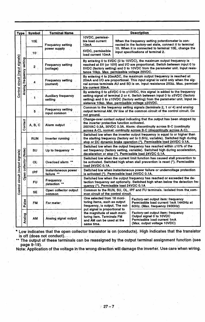
'I
One selected from l6 moni- FM For meter. toring items, such as output
frequency, is output- The out- put signal is proportional to .
Symbol Terminal Name Description 1 OVDC, permissi- ble load current 1 OE When the frequency setting potentiometer is con-
Factory-set output item: frequency Permissible load current 1 mA 1440Hz at 60Hz. (Max. frequency 2400Hz)
. -
nected in the facto&-set state, connect it to terminal 10. When it is connected to terminal 10E, change the input specifications of terminal 2.
load current 10mA
Frequency setting power supply
-10-
An&g signal output . '
toring item. Terminals FM and AM can be used at the same time.
- - .
A, B, C J
Output signal 0 - b 10VDC Permissible load current 1mA (Max. output voltage 1 OVDC)
Frequency setting (voltage)
Frequency setting (current) .
Auxiliary frequency set ti ng
Frequency setting input common
. . - .
. .
By entering 0 to 5VDC (0 to IOVDC), the maximum output frequency is reached at 5V (or 1OV) and I/O are proportional. Switch between input 0 to 5VDC (factory setting) and 0 to 10VDC from the parameter unit. Input resis- tance 10kn. Max. permissible voltage 20VDC. By entering 4 to 20mADC, the maximum output frequency is reached at 20mA and I/O are proportional. This input signal is valid only when the sig- nal across terminals AU and SD is on. Input resistance 250n. Max. permissi ble current 30mA. By entering 0 to k5VDC 0 to ilOVDC, this signal is added to the frequency setting signal of terminal 2 or 4. Switch between input 0 to i5VDC (factory setting) and 0 to AlOVDC (factory setting) from the parameter unit. Input re- sistance 1 O h . Max. permissible voltage k20VDC. Common to the frequency setting signals (terminals 2, 1 or 4) and analog output terminal AM. OV line of the common circuit of the control circuit. Do not ground. Change-over contact output indicating that the output has been stopped by the inverter protective function activated. 2OOVAC 0.3A, 30VDC 0.3A. Alarm: discontinuity across B-C (continuity across A-C), normal: continuity across B-C (discontinuity across A-C). Switched low when the inverter output frequency is equal to or higher than
-
-
4
AM
Low indicates that the open collector transistor is on (conducts). High indicates that the transistor
** The output of these terminals can be reassigned by the output terminal assignment function (see
Note: Application of the voltage in the wrong direction will damage the inverter. Use care'when wiring.
is off (does not conduct). -
page 9-1 9).

I
Inverter Type TB1' TB2 TB3 GND , FR-A241 E-5.5/7.5K M4 M4 M4 M4 FR-A241 E-1 1/15K M5 M5 M5 M5
FR-A241 E-37/45/55K M8 M8 M8 M8 FR-A241E-18.5/22/30K .M6 M6 M6 M6
7.1.5 Terminal Block Arrangement
Terminal Block for Main Circuit <200V, 400V, Series> - _
Terminal Block. for Control Circuit I I . -
Screw size P . .
< . - -I[ Common to all models Structure ............ 2-stage molded
Screw size ......... M3 - -
terminals -
RUN su .
. .
Charge lamp. (vellowY
. 1
TB1 TB2 TB3 - - - -
- - L. Jumper 0 * Screw size M8 *
I f ' I t
I
. _ - -- - _ - - -~ -.. - c200V Series>
0
c400V Series> STR
cs
. _
1 9 . . . .
. - - - . - .,__ -- .
. . +: . . I . .- , ! ;, .

7.1.6 Field Wiring Reference Table
Field wiring reference table for input (R, SI T) and output (U, VI W) -
I Note ('1) Manufacturer : AMP INCORPORATED, HARRISBURG, PA 17105 - _- ~
PHONE I 71 7-564-0100 TWX : 51 0-657-41 10 ('2) Use copper wire only . . . ,.
. '.
- 3 -
Screw torque (Pound inch)
Crimping terminals Type and 14 I type (*1) 1 Wire size
It em p-rat ing ('2) Inverter model -. . Screw size
M5 _I
Crimping terminals 170785-2 171 51 9-2 3221 28 322048 322002 3221 54 3221 53 321671
AWGlO I 75°C 59239
Hand tool 59974-1
48752-1 .
59974-1
48753-1
59974- 1
48754-1 - -
Hand tool
Dies
Hand tool
Dies
- Hand tool- . - 59974:l- - 48755- 1
Dies.
Foot operated power unit
Head 69325-3
69066
23
23 M5 AWG8 175°C
AWG6 175°C 23 M5
322053 31811 ,-
AWG4175"C . M6 40
70 * - 322074 .
A , 326896 .-AWG2 175°C M8 R-A221 E-l8.5K
-22K. ~. . - -
. -
- I
- AWG110 175°C I .
/
70 'R-A221E-.30K . - M8 322086 ,
. . - . , .. . -
. . . - .- c --
. . Dies * 48756-1'-
AWG3i0 175°C
- _ - .
'R-A221E-37K
. - -
M10 131 322095 : Foot operated . power unit -
Head
Dies
Foot operated power unit
Head
69325-3 -
69066
48758-1
69040
300430 48131
69065 Dies
WA221 E-45K M10 AWG410 175°C 13 1 170740-1
M12 219 3241 05 3OOMCM 175°C %-A221 E-55K Foot operated power unlt
Head
Dies
69040
4881 6
69060
27.- 9

13
- .
23
40
70
70
35787-0 59239 341 69
32543-0 32968 3221 28 Hand tool
322002 Dies 3221 54 322053 Hand tool 3181 1 59974-1 *
322048 59974-1
48752-1
Dies 48753-1
322074 Hand 'tool 326896 59974- 1
48755-1 Dies
322056-0 Foot operated 324083-0 power unit
t 69325r3 Head
Dies 69066-0 .
48757-1 '
Wire size /temp-rating ('2)
Crimping terminals T eandtoolt e '1
Crimping terminals I crimping toois
Screw torque (Pound inch) ~~
inverter model Screw size
* AWG10 175°C %-A241 E-5.5K -7.2K
M4 '
AWG8 175°C M5 FR-A241 E-1 1 K -1 5K
r;
AWG4 175°C FWA241E-18.5K -22K -30K
M6
AWG2 175°C FR-A241E-37K -45K
' M8
AWGWO 175°C FR-A241 E-55K
r . . > ', a _ _
. . . .
. . .
. . - . . , . . . . . . . - .
. -_ . . . . . . L - . . .
- . . .
. . . . . . . . . . . _ . . , . _ .
. , . . . . . . I -
,- - . - . . @ . -.
. . . I
I . .
.. - . . . .
. . . . . . .
. - _ . - __ - . . .
p ' i , . , - - '_ . . . . . . . . . .
. , i .I .. . - . - - I " -. - _ . i .
_ I . . . .. . . . . I
-27-10

I
Inverter Type FR-A221 E-5.5/7.5K
w w1 250 190
W2 234
WA H H1 H2 HA HB D D1 D2 DA N 10 470 454 425 8 8 270 170 100 2.3 10
284 370 430 450 580
10 600 575 540 10 15 294 169 125 3.2 10 12 600 575 535 10 15 320 190 130 3.2 12 12 700 675 635 10 15 340 195 145 3.2 12 14 700 670 630 15 15 368 205 163 3.2 14
i 14 i 900 i 870 i 830 I 15 i 15 i 405 i 215 i 190 i 3.2 i 14 I
Inverter Type FR-A241 E-5.5/7.5K FR-A241 E-1 111 5K FR-A241 E-1 8.5/22K FR-A241 E-30K FR-A241 E-37/45K FR-A241 E-55K
W W1 W2 WA H H1 H2 HA HB D D1 D2 DA N 250 190 234 10 470 454 425 8 8 270 170 100 2.3 10 300 220 284 10 600 575 540 10 15 294 169 125 3.2 10 360 290 340 12 600 575 535 10 15 320 190 130 3.2 12 450 350 430 12 700 675 635 10 15 340 195 145 3.2 12 470 370 450 14 700 670 630 15 15 368 205 163 3.2 14 600 480 580 14 900 870 830 15 15 405 215 190 3.2 14
7.1.7 Outline-Drawings ~
_ -
. . . . . . . . . - _ . . ,- , .
* ,
I - - _ _ _ Mounting bracket - - .
' (movable)
1 - . - ~ . 2-gN hole'
+- I C . . - - .
, . _ _
i
cu I
c I
vi2 ' 1 i
-y-
200V Class (Unit: mm)
FR-A221 E-30K FR-A221E-37/45K I 470 I 370 FR-A221 E-55K I 600 I 480
400V Class (Unit: mm)
27-11

7.1.8 Panel Cutting Dimensions (for mounting the heatsink outside the panel)
4-N11 screw
7
rn I
7 r I
. .
200V Series -
_ _
-- - - -
400V Series
FR-A241 E-55K I 480 I 586 I 870 I 841 I 17 I 12 I M12
. 27 -..I 2
-. .

I
7.1.9 FR-PUOPE Parameter Unit Dimension Diagram
Panel cutting dimensions for installation of the parameter unit to a panel, etc.
hole - 4 Panel
. I 70
Note: The length of the installation screw should be selected (View as seen from' the parameter unit front) so that it does not exceed the effective installation screw depth of the parameter unit.
. -
FR-PUOPE Specifications
Note: 1. When the temperature is less than about O°C, the liquid crys- tal display (LCD) may be slower in operation.And high tempera-
-ture may reduce the LCD life. D6 not expose-the li-quid crystal
- display directly to the sun. - . . . . -.
- . - . . . -. . .
. . Key board Size
24 keys (covered with polyurethane film) 127 x (H) x 70 (W) x 12 (D) A
7.1.10 FR-CUO1 Serial Communication Unit Outline Drawing . - - - .
.. , . ,
I . ' . . .
. . . - . . . . __ ni
=[ --I-- 2-424 hole Tapped threads M 3 x 6
I I
la e \ 2 - M 3 screw
Effective screw depth 4.5

7.2 OPTIONS
Use of the following options with this FR-A201 E series improves its functions Select the appropriate options. - --
. * .
Option Name - Type Application, Specifications, Etc.
- _ - ~
0-12-blt digital input - - PLG feedback control Extension analog output .
0 Orientatlon control (machine tool spindle fixed-
RS-422, RS-485 interface for computer link (serial
. -
I_ - industrial equipFent compatible function FR-EPA
. _ I
position stop control)
Computer link function __ - ~ FR-EPB communication). . - -
0 Pi control
0 12-bit digital input I/O function
Computer link + extension output function
.
Pulse train input function . .
Parameter unit (Japanese) I FR-PUOP I Interactive parameter unit using LCD display
FR-PU02E The LCD display and ten-key pad of the FR-PUO2 are indicated in English. Parameter unit (English)
Parameter unit (4 languages) I FR-PU02ER I For use in English, German, French and Spanish.
FR-ARW
FR-ARWE
Allows parameter settings to be read in batch and copied to the other inverter. The LCD display and ten-key pad of the FR-ARW are Indicated in English.
Parameter copy unit (Japanese)
Parameter copy unit (English)
Parameter copy unit (4 languages)
Accessoty cover
Serial communication unit
FR-ARWER For use in English, German, French and Spanish. Blind cover fitted after the parameter unit is re- moved from the inverter. RS485 interface for computer link (serial communica
- FR-CUO, tinn\
Noise filer which allows the inverter to conform to VDE Standard compatible noise filer I FR-ALF-(H)' I the VDE Standard (0871 Class A noise terminal volt.
Used to improve the Inverter input power factor FR-BEL-(H)' (overall power factor about 95%) and cooperate with
the power supply.
For line noise reduction (applies to small capacities)
Power factor improving DC reactor
Radio noise filter FR-BiF-(H)* . For radio noise reduction
Line noise filter FR-BSFO1 FR-BLF For line noise reduction
FR-CBLO
FR-DUO1
Cable for connection with the parameter unit or para meter copy unit. Straight or L shape type available. For operation from the control box surface.
Parameter unit cable
Digital operation panel
Surge voltage suppressing filter I FR-ASF-H 1 Absorbs surge voltage on the inverter output side.
. Applicable Inverter
.
. - . 3 ' . . I
.- . ~.
I . . . ,. .
_. ._ . . -. ..
.- . . . ,,: - . .., .
. - .
Common to' all models - c - - _ - .. - .
5.5K to 55K According to capacity
5.5K to 55K According to capacity
Common to all models
400V series 5.5 to 55K According to capacity
28-1

Option Name I Type I Application, Specifications, Etc. I Applicable Inverter I
Manual controller ~
DC tach. follower
Three speed selector
Motorized speed setter
Ratio setter
PG follower -- -
Master controller
Soft starter
Deviation detector I
Preamplifier
Pilot generator
Deviation sensor
Frequency setting potentiometer
Frequency meter ~
Calibration reslstor
. -
For independent operation .With frequency meter, frequency setting potentiometer and start switch. For joint operatlon using external signals. (0 to 5VDC. 0 to 1OVDC) (1VA)" For three-speed (high, middle, low) switching opera- tion. (1.5VA) For remote operation. Allows operation to be control- led from several places. (5VA) For ratio control. Allows ratios to be set to five in- verters. (3VA) For follow-up operation uslng the signal of a pilot generator (PG). (2VA) For parallel operation of several (up to 35) invert- ers. (5VA) For soft start and stop. Allows parallel operation and acceleratioddeceleration. (3VA) For synchronous operation. Used with a deviatlon
FR-FD sensor and synchro. (5VA)
FR-FA - Can be used as AN conversion or operational ampli- fier. (3VA)
QVAH-10 2500rpm) YVGC-5OOW- For synchronous operation (mechanical deviation NS detection). Output 90VAC/9O0
WA2WlKn For frequency setting. Wire-wound type. 2W1 KO B characteristic.
YM206RI Dedicated frequency meter (up to 12OHz scale). 1mA Moving-coil DC ammeter. RV24YN For calibration of the frequency meter. Carbon-film 1OKn type. B Characteristic.
FR-AX -
FR-AL
FR-AT
FR-FK
FR-FH
FR-FP -
FR-FG
FR-FC
. For follow-up operation. 70/35VAC 500Hz (at
Common to all models
Type for 4OOVAC class has H.
** Rated power consumption.
. Power supply specifications of the FR series 2OOVAC 50Hr,200/220VAC 60Hz controllers and setters: 11SVAC 60Hz
.I .~ . _ _ _ _ . . . . . . . . . - . . . . . . . A
' . I .
-
-
. . . . . . - . . - _ . . . . . . .~ - ~ .-
. . . . . ~. . -
I . .- . I . . . . - - . . . . . . . . . . . . . . . . . .
. -
. , . .
, , . ,
. , . . . . . . .
- .
. . . . - . . . , - ..
. . . . . . .;= , _ - -. .
. . . . .- . . . - . . . . . - _. . . . . . - I . . _.<
. . . . . . . - . . . . . . . . . . . -_ . . - . -. . . .
. . *
1 .
. . . >
- .
. . . .
. . . . . . I
. . . . - . . .- . . . . . - . . . . . . . . . . . . . . . . . - ..
. . . . . . . . . . I
. . . . - . . .
. . .
. _I - . .
. I > I ~: . . - - . _ _ _ . . . . . .
. . . . . , ! ' . . . . . . . . . . I I .
- . ' - . - . .
. . . . . . . . - . . . . . . . . I _ . .
. . -. I - -. .-
.~ . . . ,
. . . . . . . . . . . . . . . . .
. -
. .
. - . - . . . . . . .I . ~. - - . .
-. . , . , . - . . .
. , - .
, . . .. *
. . . . . . . . , .. : .
, .
. . . . . . . . . . . - .
" I
'28 - 2
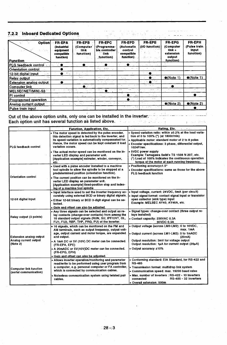
7.2.2 - - Inboard I Dedicated - Options
lrient at ion control
12-bit digital input
Output (3 points)
Extension analog output current Output
(Note 2)
Out of the above option units, only one'can be installed in the inverter: --
Each option unit has several function as listed above. . -'- - - -- - ~ ------
- I r-7 I 1
0 Used with a pulse encoder installed to a machine tool spindle to allow the spindie to be stopped at a predetermined position (orientation function). The current position can be monitored on the in- verter LED display an parameter unit. [Application example] fixed-position stop and index- ing of a machine tool spindle
0 input interface used to set the inverter frequency ac- curately using external BCD or binary digital signals.
0 Either 12-bit binary or BCD 3-digit signal can be se- iected.
0 Gain and offset can also be adiusted. 0 Any three signals can be selected and output as re-
lay contacts (change-over contacts) from among the 10 standard output signals (RUN, SU, iPF/UVT, OL, FU1, FU2, RBP, THP, PRG, PU) of the inverter. 16 signals, which can be monitored on the FM and AM terminals, such as output frequency, output voit- age, output current and motor torque, are expanded and output.
0 A 1mA DC or 5V (1OV) DC meter can be connected.
0 A 20mADC or 5V(lOV)DC meter can be connected.
0 Gain and offset can also be adiusted. 0 Allows inverter operation/monitoring and parameter
readhrvrite to be performed using user program from
(FR-EPA, EPE)
(FR-EPG, EPH)
\ '
Computer function communication^
r,
a computer, e.g. personal computer or FA controller, which is connected by communication cables.
'LG feedback control
Function,' Application, Etc. 0 The motor speed is detected by the pulse encoder,
this detection signal is fed back to the inverter, and its speed variation is automatically compensated for. Hence, the motor speed can be kept constant if load variation occurs.
0 The actual motor speed can be monitored on the in- verter LED display and parameter unit. [Application example] extruder, winder, conveyor,
0 Noiseless communication system using twisted pair cables.
~~
Ratinn. Etc. - - Speed variation ratio: within +0.2% at the load varia- tion of 0 to 100% (*) (at 1800r/min) Applicable motor: standard motor of 2 to 8 poles Encoder specifications: 3 phase, differential output, 1024Plrev. 5VDC power supply Example: Tamagawa Seiki's TS 1508 N 207, etc. (*) Load of 100% indicates the continuous operation
torque of the motor at each running frequency. Positioning accuracykl.5" Encoder specifications: same as those for the above PLG feedback function
input voltage, current: 24VDC, 5mA (per circuit) input signal format: contact signal input or transistor open collector (sink type) input Example: MELSEC AY40, AY40A, etc.
Signal types: change-over contact (three output re- lays installed) Contact capacity: 230VAC 0.3A
30VDC 0.3A Output voltage (across LMO-LM2): 0 to lOVDC,
max. 1mA Output current (across LM1-LM2): 0 to 1mADC
(20mA) Output resolution: 3mV for voltage output Output resolution: 1pA for current output (20pA) Output accuracy k10%
~~
Conforming standard: EIA Standard, for RS-422 and
Transmission format: multidrop link system Communication speed: max. 19200 baud rates Max. number of inverters : RS-422 - 10 inverters connected RS-485 - 32 inverters Overall extension: 500m
RS-485
-28- 3

* .
- - Battery backup for - - I programmed operation
Pulse train input I
Function, Application, Etc. P Allows inverter operation/monitoring and parameter
readhvrite to be performed using user program from the master station In the Mitsubishi programmable controller data link system MELSECNET/MINi-S3 (AJ71 PT32-S3) which is connected by optical fiber.
Communication is made via optical link system with- out noise. -
Pi control function is required when process control, e.g. flow rate, air volume or pressure, is carried out by the inverter.
The set value can be set from any of terminal 2: 1 or parameter unit. The measured value (feedback signal) is input to terminal 4 by a 4-20mA current sig nal. -
grammed operation. i f a power failure occurs, auto- matic operation can be continued after the power is restored. (Programmed operation is standard in the inverter. See Pr. 87.) Group selection and time-out output signal for the programmed operation are in- co rporat ed .
command input to the inverter.
_ -
Allows the timer to be battery backed for pro-
Allows a pulse train signal to be used as-a speed
_- , *,. . . . . . . . I .
. . . . . . . . . . , . . . ., : . .. 9 . 1 -
. . ? r . .
Rating, Etc.
(up to 64 inverters when used with remote I10 sta- tions)
l m min
B Max. number of inverters connected: 16 Inverters
D interstation transmission distance: 50m max.
,PI control range: proportional band 1 to 1000%
D Output signal: high limit, !ow-limit, duflng forward-ry integral time 0.1 to 3600 seconds _ _ _ . _ -
tation, during reverse rotation
- -1
I I
e Battery life: 10 years (lithium battery) - -
Permissible power failure time: - . - max. 18 hours when Pr. 2 0 0 ~ 0 (seconds selected).. Max. 30 days when Pr. 200-1- (minutes selected) -
~'Max. permissible number of pulses: 100KPPS or ies! input interface: Open collector system Input voitage/current: 24VDC, 1 OmA
.
._
- . . . c t . . . .
. . , . . . . . . . _ . I .
_ I
_ . . . .
, L.. . . . : .> ~. . . . - . . .
. I
r _
. - . . . . . . -. . - . -. .
. - - . . . -
. . . - . . . . . . . ' i . . . . .
. . . . . ' . :. I . . I .
, ,:
- . .
- .......
. 28--4

<Connection examples> . - ...: . .. ! '
- . .- , _ r
. .
- - PLG feedback contorol . - > --_
-0 Orientation control
. NFB I r 1-
Inverter Inverter
I I I 1
I
1.
I I I I
1
I
omard atation
leverse Dtation
STF I Twisted pair I shielded cabled - E
a UY
I 1024P/R (pulse encoder)
rientation error
I I
STR
SO
i' I i o
2
5 - -=r power
. - Nhen a motor with brake is used, note the release tim- ng of the brake. For more information, see the instruc- ion manual of the option.
nverter
12-bit digital input (for BCD code)
MELSEC AY40 --1
Inverter 0 PI control (for pressure control)
. T . Inverter
i i i i i i
Pump -.
. . , . _.
I
I OW 24W External power supply
(For contact signal) Extension analog output Inverter
- I , = : \ J
Current monitoring
'- 1 I
0
SD - - J I- FR-A
28-5

7.2.3 External Dedicated Options ~~
Remarks The FR-ZRW(E) used vith the Z series can- lot be used.
- Specifications, Structure, Etc. ’
Allows parameters set to application to be read in batch and easily written to another inverter. LCD and ten-key pad representations are available in three ways: Japanese, English and four languages (English, German, French, Spanish). External dimensions are the same as those of the FR-PU02 parameter unit. Can also be used as the parameter unit.
12 7 20
-Option (Type) . arameter copy unit R-ARW (Japanese) R-ARWE (English)
I languages) R-ARWER
. .
2 4 3 screw Effective depth 4.5mm
The keys marked have diff erent functions from those for the FR-PUOZ(E).
~~
Thiscover is supplied on the model which is not equipped with a pa- rameter unit.
When the parameter unit is removed from the inverter, thls cover is fitted to that posi- tion. . This cover can be fitted and removed by a single action.
,ccessory cover
- . . . . . .
r _ . /
. . . ..
3 .
An add-on unit which can be fitted after removal of the parameter unit. ;erlai communication Allows the Inverter to be rudmonitored and the parameters to be set from an FA controller or the like via the RS485 interface.
’ Multidrop link system, up to 31 inverters connected. ’ Communication speed: 1200 baud
init WCUO1
depth 4.5 40
Panel cutting dimensions for installation of FR-CUO1 to a panel, etc. Diagram viewed from the FR-CUOl front
.. .
28.- 6

Option (Type) 'DE standard (German ompatible noise filter R-ALF-(H) OD K' NOT EN STANDARD APPROVED . )
- - .
FllterType
5 FR-ALF-7.5K N '
Specifications, Structure, Etc. - _ ~-
Conforms to VDE 0871 Class A (noise terminal voltage).
!External dimension diagram Maker: Fuji Denki Kagaku (FDK) I _-_ ~
Mass Leakage (kg) 'IU,":' Appllcablelnverler A B C D E F Q
-- FR-A221E-5.5W7.5K 490 185 115 435 150 MS $6.5 12 1
_ -
: I
(Unit: mm)
'For the filters used with the Inverters of 200V 11K and up (filters 18.5K, 30K. 55K) and 400V 5.5K and up (filters 11K, 15K, 30K. 55K). contact Mitsubishi.
I
i
_ _ Gonnection diagram .
FR-ALF Inverter
Power
A different grounding connection from the above diagram may reduce the filter effect.

Option (Type) 'ower factor nproving DC eactor . for power oordination) 'R-BEL-(H) I70 K*
. .
I
_ _ _ _ _ _ _ _ _ _ _ _ _ _ _ _ _ _ _ _ _ _ _ _ _ _ _ _ ~ ~
External Dimensions (Unit: mm)
. . .
" .
w Fig. 1
.. . . . ._ . . . . . . . . - . . . : _ I
. . _ . ~ . , . -, i' , , - . .. .
Note: The numeral in the type indi- sates a motor capacity (kw).
k A 4 : .
Flg. 2
Wirlng, Etc.
.Input power factor: about 95% -
- *
FR-BEL r-O-3
Disconnect link. 3ote:l. The input power factor is im-
proved to about 95 %. 2 The link across inverter termi-
nals P-P1 must be discon- nected. (If it is not disconnected, there is no power factor improve- ment.)
3. The wiring distance from the inverter should be less than 5m.
4. The size of the cable used should be identical to or larger than that of the power supply cable (R, S, T). (See page 26-
5. Select the reactor according to the motor capacity. (If the in- verter capacity is greater than the motor capacity, select the reactor according to the motor capacity.) *To be used when a 3.7kW motor is used with a 5.5K inverter.
8.)
28-- 8

~~~
Option (Type) ,adio noise filter . R-BIF ....... 200V sed R-BIF-H ... 400V seri!
ine noise filter
applies to small apacities)
R-BSFO1
R-BLF
'arameter unit cable 'R-CBL
Specifications, Structure, Etc.
Leakage current: 4mA
n
. .. .
u) . '_
. _ - I .
- I
Inverter side * 2-43.5
Remarks Inverter
NBF 7
Power supply
. 4ote:l. This filter must not be connected to the
output circuit of the inverter. 2. The cables should be as short as possl-
ble and connected to the terminal block of the Inverter.
Power supply
Inverter NFB
4ote:l. Wind the cable 4 or more times in the same direction in each phase. (A greater effect is produced as the wind- ing times increase.)
2. If the cable size is too large to wind, use four or more filters in series and wind the cable In the same direction In each phase.
3 This filter can also be used on the out- put side as on the input side.-The wind- ing on the output side should be within
4. Use the FR-BSFOl, for capacities of 3.7kW and down. A cable of large size (38mm2 or more) cannot be used. If the cable size is large, use the FR-BLF.
. 3 turns.
. - I
Parameter unit side
Inverter side Parameter unit (Removable)
. . .
28-9

Specifications, Structure, Etc.
Note:l. Thispanel cannot be Installed on the inverter. Use this panel with the parameter unit cable.
- . -
14 . A -
2. Installation method
I 7 panel
Cut a square hole in the control box for in- stallation of this panel.
0 Fit the operation panel onto the front and the fixing frame onto the rear of the control box
. and secure them with ' screws.
Control box
_ _ . , -
.- I .
. . . .
- - Operation
. . . _ - - - .
3. Acceptable plate thickness ' 0.6 to 3.2mm
4. Parameters cannot be read or Panel cut diagram written.
I
, Rearview
Fixing frame mounting screw - _ . .
This filter suppresses a surge voltage generated in the motor terminal voltage when a 400V class motor Is driven by the inverter. Inverter FA-ASF Inverter FA-ASF
Dlmenslono mm E H Ta!ninl 8c-J 8 c m K around Ummfnefi?& 8 c m &
3.2 265 191 1 1 8,: 8 M8 M4 M6 20.0 -FR-kF- FR-A241E- H7.6K 6.SKt7.6K
FR-ASF- FR-A241E- HlSK* 1 l W m
FR-ASF- FR-A241E- H22K' 18.W22K
FR-ASF- FR-A241E- H37K 30W37K
FR-ASF- FR-A241E- HSK. 46WWK
I . lote: 1. Connect the cables from the out-
put terminals (U, V, W) of the ln- verter to the input terminals (U, V, W) of the filter and the cables from the motor terminals to the output terminals (X, Y, Z) of the filter. the cables with a Ueme care. incorrect ~~
overheat and the resis- we
- 2. The wiring length from the in- -
ter input terminals should be within 5m.
3. The wiring length from the filter terminals to the motor terminals should be less than 300m.
4. The terminals used for wiring should be sleeved solderless ter minals.
. verter output terminals to the fil-
The filters of H15K and up are slightly different in shape. -
. -
Mounting foot Terminal screw J
n
- - (H) in the type code indicates that H is attached to the code for 400V.
28 -'I 0

'I WARRANTY " _ _
1. Exceptions to the warranty, such as opportunity losses We do not warrant to reimburse you or your customers for opportunity losses, damage to produce other than ours, or any other businesses which result from a failure of our product, whether such failure has occured within the free warranty period or not.
~. - - - _ - - - - - - _ _ 2. Repair after-production stop
If we stop producing any of our models (products), we will repair such model within seven years after the month of the year when its production is stopped.
-_ - . L - _ _ - - - -
3. Delivery condition - I - _ I _-
It is understood that a standard product which does not include setting and/or adjustment in applications is delivered when it arrives on your promises, and we are not obliged to-adjust or test run such product on the spot.
_ r - _ _
- ._ - - - - - - A Application of this product ,
0 This product is not designed or manufactured-for use with any equipment or system which will be operated under conditions hazardous to life.
- - .-If you are planning to use this product in any specific application such as passenger mobile, medical, aerospace, atomic, power or submarine junction equipment or system, please refer
- to-our business department. This product is manufactured under rigorous quality control. However, safety devices should
-- be installed if this product is applied to-any facility that may result in a serious accident or
0 This product should only be used with a load of three-phase induction motor.
- -
- - -
-
loss due to a failure of this product, - - - -

MEMO
i
0
\

REVISIONS
Print Date 1 I
June, 1996
. -_
The manual number is given on the bottom left of the back cover.
*Manual Number I Revision
IB (NA) 66637-A I First edition

A MITSUBlSHl ELECTRIC CORPORATION HEAD OFFICE MlTSUBlSHl DENKI BLDG MARUNOUCHI TOKYO 100
IB (NA) 66637-A (9606) MEE Printed in Japan Specifications subject to change without notice.
.


![A Novel Parallel Traffic Control Mechanism for Cloud Computing · (200 200 200 200) (100 100 200 400) [300 300] [400] Outline Introduction Weaknesses of HTB Parallel HTB Experiments:](https://static.fdocuments.us/doc/165x107/5c61ac7f09d3f2757e8b810f/a-novel-parallel-traffic-control-mechanism-for-cloud-computing-200-200-200.jpg)