A 20 Meter Moxon Antenna - QSL.netA 20 Meter Moxon Antenna Moxons work great — and they take up...
4
From April 2009 QST © ARRL I was first licensed as a novice in 1962 as KN1VFX in southern Connecticut, and put a homebrew 807 CW rig on the air. I fed it to an 80 meter vertical outside of my second story bedroom window — with no counterpoise. (The advertisement looked great — how naïve I was!) I was able to make contact with a few local hams, and my best DX was an ARRL Official Observer (OO) report for transmitting a second harmonic on 40 meters, outside of the Novice band. Thus began my interest in antennas. I quickly gained my Technician class license and built a six element, 6 meter Yagi that I put on a small roof tower, and a home- brew 6 meter AM transmitter based on designs in ARRL publications now long lost. I fell in love with building antennas. My best DX with this antenna and rig was double-hop E-skip to California — I was hooked on antennas. Fast Forward to Today I rediscovered Amateur Radio in 1994 and purchased a new home in 1996 on a 210 foot hill ten miles north of Boston — a home I purchased partially because of my love of VHF communications. I consider myself very lucky in that I was able to pur- chase a home where my ham interests were one of the major requirements. I put a 6 foot tower on my roof with a newly built seven element 6 meter homebrew Yagi, from The ARRL Antenna Book, reliving my youth. 1 Shortly thereafter I added an 11 element, 2 meter FM Yagi (a hand-me-down from my dad, WA1INL, now SK) used for repeaters and foxhunting and another 6 foot tower with a homebrew five element, 10 meter Yagi, again from The ARRL Antenna Book. 2 A K1FO SSB 2 meter Yagi soon followed, from Directive Systems. (I was in a hurry, and decided to pur- chase — not homebrew — this one.) But after completing VHF/UHF Century Club (VUCC) on 6 meters and Worked All States (WAS) on 10 meters, I needed another challenge. I had dipoles for 80, 40, 20, 17 and 15 meters in my backyard, but they were all too low to be really very effective. Early in 2004 I had started working on 20 meter PSK31 WAS and was not happy with the 20 meter dipole. I needed a better antenna. The Moxon Rectangle I started thinking of putting a simple rotat- able dipole at the top of my HF roof tower. I then looked at the 20 meter Yagis in my ARRL Antenna Book, but they had a larger turning radius than I could use, due to the spacing of my two roof towers. I also felt I wanted to try something different. Along came the April 2004 QST and the article by Allen Baker, KG4JJH, “A 6 Meter Moxon Antenna.” 3 Somehow I had never run into the Moxon, but it seemed to have the characteristics I was looking for — smaller than a two element beam with about the same gain. 4 It also offered the front to back ratio of a three ele- ment beam. Allen also included some very nice construction methods using insulated tub- ing support blocks. Allen’s article also referenced the Moxon Web page of L. B. Cebik, W4RNL. 5 I always enjoyed reading LB’s antenna columns and articles in QST, QEX, 10-10 International News and elsewhere. Somehow I had not run across LB’s extensive writings on the Moxon and after spending quite a bit of time perusing the site I was convinced this was the antenna to experiment with. I had previously used YA Yagi analysis software, included in my ARRL Antenna Book, to analyze a number of antennas. It was time to upgrade to newer modeling software so this project gave me a reason to purchase EZNEC from Roy Lewallen, W7EL, and add that to the fun. 6 Comparison of Antennas My dipole was at 18 feet elevation on aver- age, and the Moxon would be at 36 feet at the top of my roof tower’s mast. Using EZNEC was very informative. I quickly confirmed why my dipole was so poor — it was so low that most of the radiation and reception was directed above 50°. The good news, I suppose, was that at the maximum gain (about 5.4 dBi at 60° elevation), the dipole was almost omni- directional. My dipole could hear high angle noise from all directions! Figure 1 compares the elevation plots of the two antennas and Figure 2 the azimuth. These plots were very encouraging. The Moxon should do much better, with a lower radiation angle and about 5.3 dB more gain, not to men- tion a front-to-back ratio of about 15 dB. Construction The antenna is built from 6 foot sections of telescoping aluminum tubing. Standard construction techniques were used, with a 3 inch overlap, slotting the end of the larger tube, and using stainless steel pipe clamps to secure the joints. The mast-to-boom and boom-to-element plates are 3 ⁄ 16 inch aluminum. Stainless steel saddle clamps and insulated tubing support clamps are used with these plates. I used 1 3 ⁄ 4 inch aluminum (EMT) conduit for the mast and boom. Stainless steel hardware was used throughout. I also decided to use a commercial 1:1 balun at the feed point as it lent itself to a convenient way to connect the coax and transi- tion to a balanced feed. A 20 Meter Moxon Antenna Moxons work great — and they take up less space than full size two element Yagis. Larry Banks, W1DYJ 1 Notes appear on page 40. Figure 1 — A comparison of the lower radia- tion angle and greater gain of the Moxon (red) compared to the dipole (blue). Figure 2 — This shows the superior front- to-back and greater gain of the Moxon (red) compared to the dipole (blue). Both plots are at the Moxon maximum radiation angle of 26° elevation.
Transcript of A 20 Meter Moxon Antenna - QSL.netA 20 Meter Moxon Antenna Moxons work great — and they take up...
From April 2009 QST © ARRL
I was first licensed as a novice in 1962 as KN1VFX in southern Connecticut, and put a homebrew 807 CW rig on the
air. I fed it to an 80 meter vertical outside of my second story bedroom window — with no counterpoise. (The advertisement looked great — how naïve I was!) I was able to make contact with a few local hams, and my best DX was an ARRL Official Observer (OO) report for transmitting a second harmonic on 40 meters, outside of the Novice band. Thus began my interest in antennas.
I quickly gained my Technician class license and built a six element, 6 meter Yagi that I put on a small roof tower, and a home-brew 6 meter AM transmitter based on designs in ARRL publications now long lost. I fell in love with building antennas. My best DX with this antenna and rig was double-hop E-skip to California — I was hooked on antennas.
Fast Forward to TodayI rediscovered Amateur Radio in 1994
and purchased a new home in 1996 on a 210 foot hill ten miles north of Boston — a home I purchased partially because of my love of VHF communications. I consider myself very lucky in that I was able to pur-chase a home where my ham interests were one of the major requirements. I put a 6 foot tower on my roof with a newly built seven element 6 meter homebrew Yagi, from The ARRL Antenna Book, reliving my youth.1 Shortly thereafter I added an 11 element, 2 meter FM Yagi (a hand-me-down from my dad, WA1INL, now SK) used for repeaters and foxhunting and another 6 foot tower with a homebrew five element, 10 meter Yagi, again from The ARRL Antenna Book.2 A K1FO SSB 2 meter Yagi soon followed, from Directive Systems. (I was in a hurry, and decided to pur-chase — not homebrew — this one.)
But after completing VHF/UHF Century Club (VUCC) on 6 meters and Worked All States (WAS) on 10 meters, I needed another challenge. I had dipoles for 80, 40, 20, 17 and 15 meters in my backyard, but they were all too low to be really very effective. Early in 2004 I had started working on 20 meter PSK31 WAS and was not happy with the 20 meter dipole. I needed a better antenna.
The Moxon RectangleI started thinking of putting a simple rotat-
able dipole at the top of my HF roof tower. I then looked at the 20 meter Yagis in my ARRL Antenna Book, but they had a larger turning radius than I could use, due to the spacing of my two roof towers. I also felt I wanted to try something different. Along came the April 2004 QST and the article by Allen Baker, KG4JJH, “A 6 Meter Moxon Antenna.”3 Somehow I had never run into the Moxon, but it seemed to have the characteristics I was looking for — smaller than a two element beam with about the same gain.4 It also offered the front to back ratio of a three ele-ment beam. Allen also included some very nice construction methods using insulated tub-ing support blocks.
Allen’s article also referenced the Moxon Web page of L. B. Cebik, W4RNL.5 I always enjoyed reading LB’s antenna columns and articles in QST, QEX, 10-10 International News and elsewhere. Somehow I had not run across LB’s extensive writings on the Moxon and after spending quite a bit of time perusing the site I was convinced this was the antenna to experiment with.
I had previously used YA Yagi analysis software, included in my ARRL Antenna Book, to analyze a number of antennas. It was time to upgrade to newer modeling software so this project gave me a reason to purchase EZNEC from Roy Lewallen, W7EL, and add that to the fun.6
Comparison of AntennasMy dipole was at 18 feet elevation on aver-
age, and the Moxon would be at 36 feet at the top of my roof tower’s mast. Using EZNEC was very informative. I quickly confirmed why my dipole was so poor — it was so low that most of the radiation and reception was directed above 50°. The good news, I suppose, was that at the maximum gain (about 5.4 dBi at 60° elevation), the dipole was almost omni-directional. My dipole could hear high angle noise from all directions!
Figure 1 compares the elevation plots of the two antennas and Figure 2 the azimuth. These plots were very encouraging. The Moxon should do much better, with a lower radiation angle and about 5.3 dB more gain, not to men-tion a front-to-back ratio of about 15 dB.
ConstructionThe antenna is built from 6 foot sections
of telescoping aluminum tubing. Standard construction techniques were used, with a 3 inch overlap, slotting the end of the larger tube, and using stainless steel pipe clamps to secure the joints.
The mast-to-boom and boom-to-element plates are 3⁄16 inch aluminum. Stainless steel saddle clamps and insulated tubing support clamps are used with these plates. I used 13⁄4 inch aluminum (EMT) conduit for the mast and boom. Stainless steel hardware was used throughout. I also decided to use a commercial 1:1 balun at the feed point as it lent itself to a convenient way to connect the coax and transi-tion to a balanced feed.
A 20 Meter Moxon AntennaMoxons work great — and they take up less space than full size two element Yagis.
Larry Banks, W1DYJ
1Notes appear on page 40.
Figure 1 — A comparison of the lower radia-tion angle and greater gain of the Moxon (red) compared to the dipole (blue).
Figure 2 — This shows the superior front-to-back and greater gain of the Moxon (red) compared to the dipole (blue). Both plots are at the Moxon maximum radiation angle of 26° elevation.
From April 2009 QST © ARRL
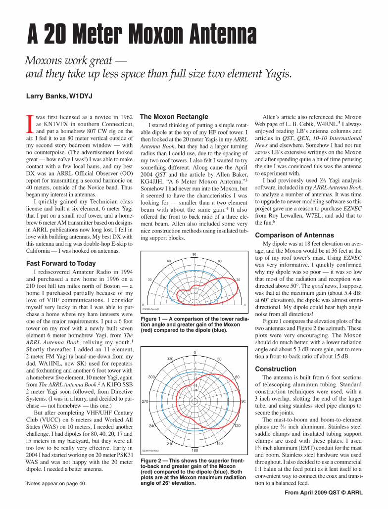
Table 1Required Parts and Suggested SuppliersPart Size Quantity SupplierAluminum tubing 3⁄4" × 6' 4 Texas Towers 5⁄8" × 6' 4 5⁄8" × 1' 1 1⁄2" × 4' 9" 2 1⁄2" × 3' 7" 2 1⁄2" × 1' 3" 4Aluminum plates Local surplus aluminum dealer or Mast-to-boom 3⁄16" × 8" × 8" 1 home supply store Boom-to-element 3⁄16" × 4"×12" 2 Corner plates, 45º 1⁄16" × 4" × 4" 4 Tubing support 1⁄16" × 17⁄8" × 7⁄8" 6EMT boom 13⁄4" × 10" 1 Local hardware storeFiberglass rod McMaster-Carr Driven element 5⁄8"× 1' 1 Sides 3⁄8" × 1' 4" 2 Corners 3⁄8" × 6" 8Insulated tubing support 3⁄4" 6 DX EngineeringStainless saddle clamp 13⁄4" 12 DX Engineering1:1 balun 1 Unadilla “W2AU” 1/1Stainless steel pipe clamps Various 12 Home supply storeStainless steel hardware Various Various Home supply/McMaster-Carr
Figure 3 — Details and dimensions of the antenna and various mounting brackets.
The corners need some explanation. Aluminum tubing bent at 90° would normally be used. I had read of several hams having difficulty bending aluminum tubing, however. Based on another one of W4RNL’s articles suggesting the use of “L-stock,” I decided
to use corner plates to sandwich the tubing (see Figure 6).7 I added fiberglass rods inside the tubing to take care of any deformation of the tubing by the hardware. Although a more complex design, this was easier for me to fab-ricate with my modest workshop.
See Figures 4 through 10 for construction details and Table 1 for a list of parts and the suppliers I used.
ResultsResults for a home-brew antenna come in
two forms. The primary measure is how well the antenna performs electrically, but how long the antenna stays up is also important! The mechanical design of a home-brew antenna is just as important as the electrical design, espe-cially in New England.
Mechanical PerformanceLet me first address the mechanical design.
I erected this antenna in the fall of 2004. As I write this in the winter of 2007-8 I am in my fourth New England winter since erecting it. This has allowed me to see how it handled wind, snow and ice. Each of the first two winters saw a failure — during the first winter a corner plate came off and the antenna quickly became a complex 11⁄2 element beast with very strange RF behavior. It still worked, sort of. When I investigated this failure I realized that the #6 hardware I originally used was not sufficient, especially because I just used lock washers and nuts. Switching to #10 hardware with lock washers and locking (nylon insert) hex nuts fixed this design deficiency (see Figure 6).

From April 2009 QST © ARRL
sible with minimal test equipment. My SWR testing has been with my Autek Research RF-1 SWR analyzer. My receiver testing has been with my Kenwood TS-2000 using its S-meter for gathering data. Since modern transceiver manufacturers usually do not adopt the classically accepted S-unit of 6 dB, I have used 5 dB for the TS-2000. (I have seen postings of from 4 to 6 dB for the TS-2000 S-meter calibration, and as typical transceivers do not have linear S-meters, I took this as a reasonable compromise.)
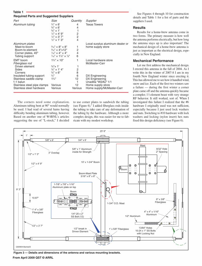
Naturally, the first thing I checked was the SWR. Figure 12 compares the EZNEC prediction with my measured SWR. The test data is with the Moxon on my test stand on my back deck using my Autek analyzer and about 20 feet of LMR-240 coax, and when it was installed on my roof. Note that the Autek resolution is 0.1 units, so the measured data is stepped. I cannot explain the upward shift in frequency while on my roof, other than to assume it is the effect of the real life environment and the 10 meter Yagi 6 feet below
During the second winter the SWR became intermittent. Usually fine, it would go to infinity as soon as I started a QSO with a station in an unconfirmed DXCC entity. Again, I discovered this was due to the #6 hardware that I used to connect the balun to the driven element. I should have taken the antenna down from the tower after the first failure and changed all of the hardware as above, but that was a lot of work and I didn’t — lesson learned!
SWR PerformanceAccepting the init ial
mechanical failures, which only reduced the amount of time I have been able to use the Moxon, the really impor-tant information is how does it work with RF. I have tried to be as quantitative as pos-
Figure 4 — Driven element boom-to-element detail. Note that the assembly is upside down as shown and the Balun hangs down in use. The fiberglass rod can be seen inside the 1⁄2 inch break in the driven element.
Figure 5 — Reflector boom-to-element detail. The small aluminum plates on top of the insulated pipe clamps were added for strength.
Figure 6 — Detail of the corner construc-tion showing the two triangular plates and locking hex nuts. For an explanation of why the hardware looks new and the aluminum looks old, see the discussion about mechanical performance.
Figure 9 — Moxon pointing straight up on my test stand for initial testing. My HF roof tower with the five element 10 meter beam can be seen waiting for the antenna to be mounted.
Figure 7 — Detail of the mast-to-boom plate.
Figure 10 — Moxon mounted on the HF roof tower above the five element 10 meter beam. The roof ladder shown helps save the shingles and enhances safety.
Figure 8 — The antenna under construction in my backyard.
From April 2009 QST © ARRL
Did you enjoy this article? Cast your vote at:
www.arrl.org/members-only/qstvote.html
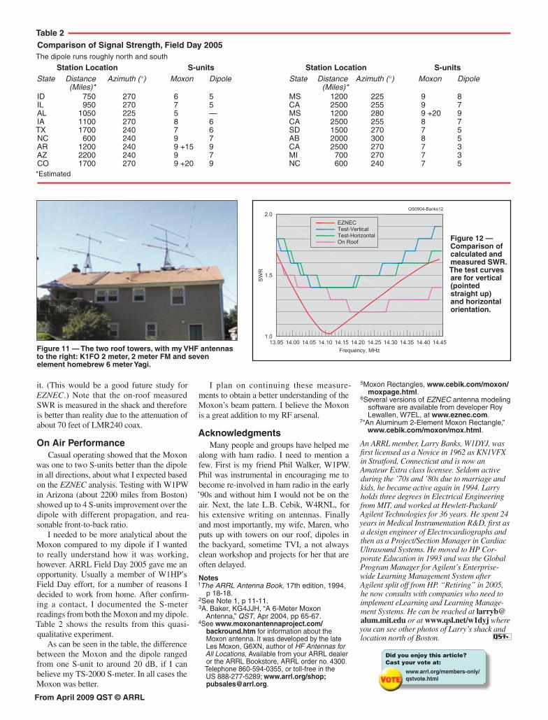
Figure 12 — Comparison of calculated and measured SWR. The test curves are for vertical (pointed straight up) and horizontal orientation.
Figure 11 — The two roof towers, with my VHF antennas to the right: K1FO 2 meter, 2 meter FM and seven element homebrew 6 meter Yagi.
it. (This would be a good future study for EZNEC.) Note that the on-roof measured SWR is measured in the shack and therefore is better than reality due to the attenuation of about 70 feet of LMR240 coax.
On Air PerformanceCasual operating showed that the Moxon
was one to two S-units better than the dipole in all directions, about what I expected based on the EZNEC analysis. Testing with W1PW in Arizona (about 2200 miles from Boston) showed up to 4 S-units improvement over the dipole with different propagation, and rea-sonable front-to-back ratio.
I needed to be more analytical about the Moxon compared to my dipole if I wanted to really understand how it was working, however. ARRL Field Day 2005 gave me an opportunity. Usually a member of W1HP’s Field Day effort, for a number of reasons I decided to work from home. After confirm-ing a contact, I documented the S-meter readings from both the Moxon and my dipole. Table 2 shows the results from this quasi-qualitative experiment.
As can be seen in the table, the difference between the Moxon and the dipole ranged from one S-unit to around 20 dB, if I can believe my TS-2000 S-meter. In all cases the Moxon was better.
Table 2 Comparison of Signal Strength, Field Day 2005The dipole runs roughly north and south
Station Location S-units Station Location S-unitsState Distance Azimuth (°) Moxon Dipole State Distance Azimuth (°) Moxon Dipole (Miles)* (Miles)*ID 750 270 6 5 MS 1200 225 9 8IL 950 270 7 5 CA 2500 255 9 7AL 1050 225 5 — MS 1200 280 9 +20 9IA 1100 270 8 6 CA 2500 255 8 7TX 1700 240 7 6 SD 1500 270 7 5NC 600 240 9 7 AB 2000 300 8 5AR 1200 240 9 +15 9 CA 2500 270 7 3AZ 2200 240 9 7 MI 700 270 7 3CO 1700 270 9 +20 9 NC 600 240 7 5*Estimated
I plan on continuing these measure-ments to obtain a better understanding of the Moxon’s beam pattern. I believe the Moxon is a great addition to my RF arsenal.
AcknowledgmentsMany people and groups have helped me
along with ham radio. I need to mention a few. First is my friend Phil Walker, W1PW. Phil was instrumental in encouraging me to become re-involved in ham radio in the early ’90s and without him I would not be on the air. Next, the late L.B. Cebik, W4RNL, for his extensive writing on antennas. Finally and most importantly, my wife, Maren, who puts up with towers on our roof, dipoles in the backyard, sometime TVI, a not always clean workshop and projects for her that are often delayed.
Notes1The ARRL Antenna Book, 17th edition, 1994,
p 18-18.2See Note 1, p 11-11.3A. Baker, KG4JJH, “A 6-Meter Moxon
Antenna,” QST, Apr 2004, pp 65-67.4See www.moxonantennaproject.com/
backround.htm for information about the Moxon antenna. It was developed by the late Les Moxon, G6XN, author of HF Antennas for All Locations, Available from your ARRL dealer or the ARRL Bookstore, ARRL order no. 4300. Telephone 860-594-0355, or toll-free in the US 888-277-5289; www.arrl.org/shop; [email protected].
5Moxon Rectangles, www.cebik.com/moxon/moxpage.html.
6Several versions of EZNEC antenna modeling software are available from developer Roy Lewallen, W7EL, at www.eznec.com.
7“An Aluminum 2-Element Moxon Rectangle,” www.cebik.com/moxon/mox.html.
An ARRL member, Larry Banks, W1DYJ, was first licensed as a Novice in 1962 as KN1VFX in Stratford, Connecticut and is now an Amateur Extra class licensee. Seldom active during the ’70s and ’80s due to marriage and kids, he became active again in 1994. Larry holds three degrees in Electrical Engineering from MIT, and worked at Hewlett-Packard/Agilent Technologies for 36 years. He spent 24 years in Medical Instrumentation R&D, first as a design engineer of Electrocardiographs and then as a Project/Section Manager in Cardiac Ultrasound Systems. He moved to HP Cor-porate Education in 1993 and was the Global Program Manager for Agilent’s Enterprise-wide Learning Management System after Agilent split off from HP. “Retiring” in 2005, he now consults with companies who need to implement eLearning and Learning Manage-ment Systems. He can be reached at [email protected] or at www.qsl.net/w1dyj where you can see other photos of Larry’s shack and location north of Boston.