
993754-1-913(NP), Revision 0, 'Regulatory Guide 1.152 ...
62
i n v'e. ns'. s 0 TM Operations Management i n ve. n s'.w s" Triconex Project: PG&E PROCESS PROTECTION SYSTEM REPLACEMENT Purchase Order No.: 3500897372 Project Sales Order: 993754 PACIFIC GAS & ELECTRIC COMPANY NUCLEAR SAFETY-RELATED PROCESS PROTECTION SYSTEM REPLACEMENT DIABLO CANYON POWER PLANT REGULATORY GUIDE 1.152 CONFORMANCE REPORT Document No. 993754-1-913 (-NP) Revision 0 September 6, 2011 Non -Proprietary copy per I OCFR2.390 - Areas of Invensys Operations Management proprietary information, marked as [P], have been redacted based on 1OCFR2.390(a)(4). Name Sign re/. - Title Author: G. McDonald Applicaton Engineer Reviewer: K. Harris ,, -•. Project Engineer Approval: ,R. Shaffer ""' Project Manager
Transcript of 993754-1-913(NP), Revision 0, 'Regulatory Guide 1.152 ...

i n v'e. ns'. s0 TM
Operations Managementi n ve. n s'.w s"
Triconex
Project: PG&E PROCESS PROTECTION SYSTEM REPLACEMENTPurchase Order No.: 3500897372Project Sales Order: 993754
PACIFIC GAS & ELECTRICCOMPANY
NUCLEAR SAFETY-RELATEDPROCESS PROTECTION SYSTEM
REPLACEMENTDIABLO CANYON POWER PLANT
REGULATORY GUIDE 1.152CONFORMANCE REPORT
Document No. 993754-1-913 (-NP)
Revision 0
September 6, 2011
Non -Proprietary copy per I OCFR2.390- Areas of Invensys Operations Management proprietary
information, marked as [P], have been redacted basedon 1OCFR2.390(a)(4).
Name Sign re/. - TitleAuthor: G. McDonald Applicaton EngineerReviewer: K. Harris ,, -•. Project EngineerApproval: ,R. Shaffer ""' Project Manager

n !- * V" 2. n- s" ý.j s-o • -• n V" e. n1s.ý 5",Is"
Operations Management TriconexDocument: I993754-1-913 I Title: I Regulatory Guide 1. 152 Conformance ReportRevision: 0 Page: 2 of 62 Dt:09/6/11
Document Change HistoryRevision Date Change Author
0 09/6/11 Initial issue. G. McDonaldG3. McDonald

n V e. n s-.ý=j s-Im i n V e. n s-.ý=j s-
Operations Management TriconexDocument: 993754-1-913 Title: Regulatory Guide 1. 152 Conforniance Report
Revision: 0 Page: 3 of 62 1 Date: 09/6/11
Table of Contents
L ist of T ab les ............................................................................................................ 5
L ist of F igu res ........................................................................................................... 6
1.0 In trod u ction .................................................................................................... 71.1 V 10 Tricon Conform ance to Regulatory Guide 1. 152 .................................................................................... 71.2 S c o p e ............................................................................................................................................................... 91.3 Abbreviations and A cronym s .......................................................................................................................... 91.4 Definitions ..................................................................................................................................................... 11
2.0 Process Protection System Replacement Scope ........................................ 122.1 Existing System ............................................................................................................................................. 122.2 Replacem ent System ..................................................................................................................................... 132.3 Tricon System Architecture ........................................................................................................................... 152.3.1 Tricon Chassis Configurations ...................................................................................................................... 15
3.0 Secure Development Environment for the PPS Application ................... 183.1 System Integration Processes at Invensys Operations Management Development Facility .......................... 203.2 V 10 Tricon D evelopm ent Environm ent Security (Integration Facility) ........................................................ 203.2.1 Access Control .............................................................................................................................................. 21
3.2.1.1 Physical A ccess ........................................................................................................................ 213.2.1.2 N etwork Access ........................................................................................................................ 22
3.2.2 Personnel Security ......................................................................................................................................... 223.2.2.1 Background Checks .................................................................................................................. 223.2.2.2 Em ployee Separation ................................................................................................................ 23
3.2.3 Adm inistrative Controls ................................................................................................................................ 233.2.4 Application Program Configuration and Source Code Control ..................................................................... 233.3 V 10 Tricon Platform Design Features ........................................................................................................... 243.3.1 H ardware D esign Features ............................................................................................................................ 25
3.3.1.1 Tricon redundancy .................................................................................................................... 253.3.1.2 M aintenance/Debug front-panel ports ...................................................................................... 253.3.1.3 Tricon K eysw itch ..................................................................................................................... 253.3.1.4 Channel Out-of Service Sw itches ............................................................................................. 26
3.3.2 Software/Firm w are Security ......................................................................................................... : ................ 263.3.2.1 TS 1131 Application Program Protection .................................................................................. 263.3.2.2 TS 1131 role-based access ......................................................................................................... 273.3.2.3 Firm w are upgrades ................................................................................................................... 28
3.3.3 Com m unications Security ............................................................................................................................. 283.3.3.1 Tricon Com m unication M odule ................................................................................................ 293.3.3.2 Com m unication Bus ................................................................................................................. 303.3.3.3 IOCCOM Processor .................................................................................................................. 303.3.3.4 Dual-Port RAM ........................................................................................................................ 30

n V e. n s-.9 s-TM n V e. n s-.ýj s-
Operations Management TriconexDoe ment: 993754-1-913 Title: Regulatory Guide 1. 15 2 Conformance ReportRevision: 0 Page: 4 of 62 1 Date: 1 09/6/11
3.3 .3.5 T C M C onfiguration .................................................................................................................. 303.3.3.6 End-to-End Communication Link Integrity .............................................................................. 31
4.0 Regulatory Guide 1.152 Conformance Table ........................................... 321.0 Functional and Design Requirements ............................................................................................................ 322.0 Secure Development and Operational Environment for the Protection of Digital Safety Systems ............... 332 .1 C on cep ts P h ase .............................................................................................................................................. 3 72 .2 R equ irem ents P hase ...................................................................................................................................... 4 0
2 .2 .1 S y stem F eatures ............................................................................................................................ 4 02.2.2 D evelopm ent A ctivities ................................................................................................................. 43
2 .3 D esig n P h ase ................................................................................................................................................. 4 32 .3 .1 S y stem F eatu res ............................................................................................................................ 4 32.3.2 D evelopm ent A ctivities ................................................................................................................. 47
2 .4 Im p lem entation P h ase ................................................................................................................................... 4 82 .4 .1 S y stem F eatures ............................................................................................................................ 4 82.4 .2 D evelopm ent A ctivities ................................................................................................................. 49
2 .5 T e st P h ase ...................................................................................................................................................... 5 22 .5 .1 Sy stem F eatu res ............................................................................................................................ 522.5.2 D evelopm ent A ctivities ................................................................................................................. 54
5.0 R eferences ..................................................................................................... 56
A ppendix A ............................................................................................................. 58
1.0 Potential Vulnerabilities of V 10 Tricon ........................................................................................................ 59

i n v . I-n S, Im n V e. nl s* .Y= s
Operations Management TriconexDocument: 1993754-1-913 Title: I Regulatory Guide 1.152 Conformance ReportRevision: 0 Page: 5 of 62 Date: I 09/6/11
LIST OF TABLES
Table 1. Invensys O perations M anagem ent Lifecycle ................................................................................................. 19

i n ve. n s.y s-Operations Management
i n V e. n s " s
TriconexDocument: 1993754-1-913 I Title: I Regulatory Guide 1.152 Confornance ReportRevision: 0 Page: 6 of 62 Date:. 09/6/11
LIST OF FIGURES
Figure 1. W estinghouse PW R Protection Scheme ..................................................................................................... 7Figure 2. Existing DCPP Reactor Protection System with Eagle 21 ..................................................................... 12Figure 3. Process Protection System Replacement .................................................................................................. 13Figure 4. PPS Replacement Architecture .................................................................................................................... 14F igure 5 . T ricon M ain C h assis ..................................................................................................................................... 15F igure 6 . I/O B u s P orts ................................................................................................................................................ 16Figure 7. VI 0 Tricon Pathway for Network Communications ............................................................................... 29

i n v'e. n s'.: s,0 0 Im
Operations Managementi n V e. n s " s
TriconexDocument: 1993754-1-913 1 Title: I Regulatory Guide 1.152 Conformance ReportRevision: 0 Page: 7 of 62 Date: 09/6/11
1.0 INTRODUCTION
The purpose of this document is to address the Diablo Canyon Power Plant (DCPP) ProcessProtection System (PPS) Replacement project with respect to conformance to the guidancecontained in NRC Regulatory Guide (RG) 1.152, "Criteria for Use of Computers in SafetySystems of Nuclear Power Plants" (Reference 1). The project replaces the Westinghouse Eagle21 Process Protection System, currently housed in Protection Racks 1-16 in the Cable SpreadingRoom, with a V1O Tricon-based PPS. The scope of the replacement concept is illustrated by theshaded area in Figure 1 below. Section 2.0 of this document provides an overview of thespecific changes being made to the PPS.
® PWR Protection Concept
Figure 1. Westinghouse PWR Protection Scheme
1.1 V10 Tricon Conformance to Regulatory Guide 1.152
The regulation section 10 CFR 50.55a(h) requires that protection systems for nuclear powerplants meet the requirements of IEEE Std. 603-1991 (Reference 2) and the correction sheet datedJanuary 30, 1995. With respect to the use of computers in safety systems, IEEE Std. 7-4.3.2-2003 (Reference 3) specifies computer-specific requirements to supplement the criteria and

i n v'e. n s'.* s"• • i n V e. n s-'.ýi s"
Operations Management TriconexDocument: 1 993754-1-913 1 Title: I Regulatory Guide 1. 152 Conformance ReportRevision: 0 Page: 8 of 62 Date: 09/6/11
requirements of IEEE Std. 603-1998, "Standard Criteria for Safety Systems for Nuclear PowerGenerating Stations."
IEEE Std. 7-4.3.2-2003 evolved from IEEE Std. 7-4.3.2-1993 and reflects advances in digitaltechnology. It also represents a continued effort by IEEE to support the specification, design,and implementation of computers in safety systems of nuclear power plants. In addition, IEEEStd. 7-4.3.2-2003 specifies computer-specific requirements to supplement the criteria andrequirements of IEEE Std. 603-1998.
Clause 5.9, "Control of Access," of IEEE Std. 7-4.3.2-2003 refers to the requirements in Clause5.9 of IEEE Std. 603-1998, which states, "The design shall permit the administrative control ofaccess to safety system equipment. These administrative controls shall be supported byprovisions within the safety systems, by provision in the generating station design, or by acombination thereof." IEEE Std. 7-4.3.2-2003 does not provide any additional guidance forcomputer-based system equipment and software systems to address the IEEE-603-1998 accesscontrol requirements of Clause 5.9 or the independence requirements of Clause 5.6.3.Consequently, the NRC issued regulatory guidance in RG 1.152 concerning the security of thedesign and development phases of computer-based safety systems that was intended to addressthe criteria within these clauses. The regulatory guidance clarified the staff's regulatorypositions specifically concerned with the access controls and protective measures applied to thedevelopment of digital safety systems and with the ability of security features within the systemto maintain system integrity and reliability in the event of inadvertent operator actions andundesirable behavior of connected equipment. The guidance was not intended to address theability of those security features to thwart malicious cyber attacks. Rather, the requirements of10 CFR 73.54, "Protection of Digital Computer and Communication Systems and Networks,"specifies the requirements for licensees to develop cyber-security plans and programs to protectcritical digital assets, including digital safety systems, from malicious cyber attacks, with RG5.71, "Cyber Security Programs for Nuclear Facilities" (Reference 4), providing guidance tomeet the requirements of 10 CFR 73.54.
Secure Development Environment is defined as the condition of having appropriate physical,logical and programmatic controls during the system development phases (i.e., concepts,requirements, design, implementation, testing) to ensure that unwanted, unneeded andundocumented functionality (e.g., superfluous code) is not introduced into digital safety systems.
Secure Operational Environment is defined as the condition of having appropriate physical,logical and administrative controls within a facility to ensure that the reliable operation of digitalsafety systems are not degraded by undesirable behavior of connected systems and eventsinitiated by inadvertent access to the system.
The establishment of a Secure Development and Operational Environment (SDOE) for digitalsafety systems, in the context of Regulatory Guide 1.152, refers to: (1) measures and controlstaken to establish a secure environment for development of the digital safety system againstundocumented, unneeded and unwanted modifications and (2) protective actions taken against apredictable set of undesirable acts (e.g., inadvertent operator actions or the undesirable behavior

i n ve. n s>.i s"• • TM n. V" e. n. s" .ý= s"
Operations Management TriconexDocument: I993754-1-9 13 I Title: I Regulatory Guide 1. 152 Conformance ReportRevision: 0 Page: 9 of 62 1 Date: 1 09/6/11
of connected systems) that could challenge the integrity, reliability, or functionality of a digitalsafety system during operations. These SDOE actions may include adoption of protective designfeatures into the digital safety system design to preclude inadvertent access to the system and/orprotection against undesirable behavior from connected systems when operational.
The Tricon is a mature, flexible, robust, and fault tolerant controller and, as such, is ideallysuited for critical control and safety-related applications in nuclear power plants. The InvensysOperations Management V10 Tricon Topical Report 7286-545-1 (Reference 6) demonstrates thatthe Tricon is sufficiently robust, and the quality of manufacturing hardware and operatingsoftware is sufficient for use in Nuclear Power Plant (NPP) and nuclear facility safety-relatedsystems. In addition, the generic conformance of the V10 Tricon platform to RG 1..152 isaddressed in Invensys Operations Management document NTX-SER-10-14 (Reference 8).Based on the definition of "security" in the RG and discussions in this document, the V1O TriconPPS conforms to the guidance in Regulatory Positions 2.1 through 2.5 contained in RG 1.152.
1.2 Scope
The scope of this document is the conformance of the Tricon-based DCPP PPS Replacement toRegulatory Guide 1.152 for application phase development, testing, and delivery of the system.Conformance of the system during the Operational Phase (Secure Operating Environment) isaddressed by PG&E in other document(s).
Section 3.0 of this document provides a description of the Tricon PPS ReplacementDevelopment Environment Security during application design, manufacturing, and testing priorto delivery to DCPP.
Section 4.0, Regulatory Guide 1.152 Conformance Table, provides additional details on V10Tricon conformance to Regulatory Positions 2.1 through 2.5 of the Regulatory Guide. AppendixA, Vulnerability Assessment of PPS, discusses potential vulnerabilities of the Tricon PPSReplacement that are not mitigated by platform or application design.
1.3 Abbreviations and Acronyms
ACK Acknowledge (e.g., during network communication handshaking)Al Analog InputALS Advanced Logic SystemAO Analog OutputCFR Code of Federal RegulationsCOM Communication(s)COMBUS Communications BusCOTS Commercial Off-The Shelf (software)CRC Cyclic Redundancy CheckD3 Diversity and Defense in DepthDCPP Diablo Canyon Power Plant

in v'e. n siv9 so Im i n V " e. n " s '.ý4 s "
Operations Management TriconexDocument: 1993754-1-913 I Title: I Regulatory Guide 1. 152 Conforma~nce ReportRevision: 0 Page: 10 of 62 Date: 09/6/11
DCS Distributed Control SystemDI Digital InputDO Digital OutputDPRAM Dual-Port Random Access MemoryEDM Invensys Engineering Department ManualESFAS Engineering Safety Features Actuation SystemETSX Enhanced Tricon System ExecutiveEXP Tricon Expansion ChassisFPGA Field Programmable Gate ArrayHSI Human/System InterfaceIEEE Institute of Electrical and Electronics EngineersI/O Input/OutputIOCCOM I/O Controller/Communications ControllerIP Internet ProtocolISG Interim Staff GuidanceIV&V Independent Verification & ValidationMP 3008N Main ProcessorNAK Negative Acknowledgement (e.g., during communication handshaking)NPP Nuclear Power PlantNRC U.S. Nuclear Regulatory CommissionNSIPM Invensys Nuclear Systems Integration Program ManualNUREG Nuclear RegulatoryOSI Open Systems InterconnectP2P Peer-to-PeerPG&E Pacific Gas & ElectricPLC Programmable Logic ControllerPPM Invensys Project Procedures ManualPPS Process Protection SystemRG Regulatory GuideRPS Reactor Protection SystemRTS Reactor Trip SystemRXM Remote Expansion ChassisSAP System Application ProtocolSER Safety Evaluation ReportSSPS Solid State Protection SystemSVDU Safety(-related) Video Display UnitTCM Tricon Communication ModuleTCP Transmission Control ProtocolTMR Triple-Modular RedundantTSAA Tricon System Access ApplicationTR Technical ReportVDU Video Display Unit

i \V" 2. nl s".: s-• " fm i n• V" e. n• s".ý ,1s"
Operations Management TriconexDocument: I993754-1-913 I Title: I Regulatory Guide 1. 152 Conforma 'nce ReportRevision: 0 Page: 11 of 62 Date: 09/6/11
1.4 Definitions
ChannelAn arrangement of components, modules, and software as required to generate a singleprotective action signal when required by a generating station condition. A channel loses itsidentity where single action signals are combined.
ModuleAny assembly of interconnected components that constitutes an identifiable device, instrument,or piece of equipment. A module can be disconnected, removed as a unit, and replaced with aspare. It has definable performance characteristics that permit it to be tested as a unit. A modulecan be a card or other subassembly of a larger device, provided it meets the requirements of thisdefinition.
ComponentsItems from which the system is assembled (such as resistors, capacitors, wires, connectors,transistors, tubes, switches, and springs).
Protection SetA protection set is a physical grouping of process channels with the same Class-i electricalchannel designation (I, II, III, or IV). Each of the four redundant protection sets is provided withseparate and independentpower feeds and process instrumentation transmitters. Thus, each of the four redundantprotection sets is physically and electrically independent of the other sets.
Protective FunctionA protective function is the sensing of one or more variables associated with a particulargenerating station condition, signal processing, and the initiation and completion of theprotective action at values established in the design bases.
Protective ActionA protective action can be at the channel or the system level. A protective action at the channellevel is the initiation of a signal by a single channel when the variable sensed exceeds a limit. Aprotective action at the system level is the initiation of the operation of a sufficient number ofactuations to effect a protective function.
Diversity and Defense-In-Depth (D&D-in-D or D3)Requirement imposed on the Protection System design to ensure that required protective actionswill occur to protect against Anticipated Operational Occurrences and Design Basis Accidents(as described in the FSARU) concurrent with a common cause failure (usually assumed to besoftware) that disables one or more echelons of defense.
Single FailureAny single event that results in a loss of function of a component or components of a system.Multiple failures resulting from a single event shall be treated as a single failure.

n ve. n s".9 s-Operations Management
i n V'e n '. s -
TriconexDocument: 1993754-1-913 Title: I Regulatory Guide 1.152 Confora nce ReportRevision: 0 Page: 12 of 62 1 Date: 1 09/6/11
2.0 PROCESS PROTECTION SYSTEM REPLACEMENT SCOPE
2.1 Existing System
The Process Protection System (PPS) monitors plant parameters, compares them againstsetpoints and provides signals to the Solid State Protection System (SSPS) if operating limits areexceeded. The SSPS evaluates the signals and performs Reactor Trip System (RTS) andEngineered Safety Feature Actuation (ESFAS) functions to mitigate the event that is in progress.There are four separate PPS rack sets. Separation of redundant process channels begins at theprocess sensors and is maintained in the field wiring, containment penetrations, and processprotection racks to the two redundant trains in the SSPS logic racks. Redundant processchannels are separated by locating the electronics in different PPS rack sets.
The Westinghouse Eagle 21 PPS comprises Protection Racks 1-16. The functional relationshipof Eagle 21 with the other components of the overall Reactor Protection System (RPS) isillustrated in Figure 2 below.
Typ of 2 Trains
Dependent isolated Class IIoutputs to control systems
Isolated Class IIoutputs to AMSAC
Readw RTyS ShW ESFAS ESF CVI"Trip snsom erwm srmlom AdudwUom B
/ X/ Is
Figure 2. Existing DCPP Reactor Protection System with Eagle 21

i n v'e. n s'.g s"fm
Operations Managementinv e. n s't s"
TriconexDocument: 1993754-1-913 1 Title: I Regulatory Guide 1.152 Conformance ReportRevision: 0 Page: 13 of 62 Date: I 09/6/11
2.2 Replacement System
The project replaces the Westinghouse Eagle 21 protection sets currently housed in ProtectionRacks I - 16. Figure 3 shows the Replacement PPS system.
NIS, 89ft *uAM&AL.,m*A*". "%%no ftd Ifixt
ktý Qw
U
lwwbld *186vtCis 11 Od" fit
Ow". 11 PAW
vg=W~d y,*dvaifi
S~ PAMkhAuffW-fl
saw
* L~.IN.fl..Rings Ti. Jrp.iwmUl by D&6
Figure 3. Process Protection System Replacement
Replacement PPS protective functions are implemented in four (4) redundant protection sets,each using a software-based Invensys Triconex Tricon system to mitigate events where existingdiverse and independent automatic mitigating functions are available per the Eagle 21 DiversityReport. For the events where existing analyses credit manual mitigative action, automaticprotective functions are performed in a diverse Class I E CS Innovations, LLC Advanced LogicSystem (ALS). The Diversity and Defense in Depth analysis for the Replacement PPS isdocumented in PG&E Topical Report, "Process Protection System Replacement Diversity &Defense-in-Depth Assessment" (Reference 15).

i n ve. n s..: sTM
Operations Managementi nf V E. n s " s-
TriconexI Document: 1993754-1-913 Title: I Regulatory Guide 1.152 Confornance Report
Revision: 0 Page: 14 of 62 1 Date: 1 09/6/11
Figure 4 shows the PPS Replacement Architecture with Tricon and ALS hardware, typical ofeach protection set. Interfaces between the Tricon and other plant systems in the OperatingEnvironment are shown.
ALS Tapattra A TRICON
RTDtn Inpula (4-20 mA OhmS)(2003 Platinum) Tdp to SOPS
Containnent Spray (D ")a )
RCS low, (RS.48) M:VS/1
) = U
( 0(RS-42 2)
Contam enant Pr es ure T l Plant Pro -n r Com put er(4-2 mA) ; • RS-422 (PPC) Gat(ý20RCS FI-•
PZR pr P•u (420 n'A) I(4-20 MA) AP S ST
Pbomlotion •S Fllur. Main Ann.nolaor
(DM 10•t_)___ System(MAS)
(DiogOtra is n)dn Mrtln
Input Taps and (-0 Control Board Re1ardn & Indicators
Isolation Devices Control Systems(Nota 2) AMSAC Signal, 6 ay0 L-nai
Smsantina Pras-ora t~ot. 3) i4-2 nA) Turtmn Impuien Prnsnura* tnoofiow
PZR 1-el InputTuCn• u• PMT1 (4-20 r TRICON T
Posde. =pl Pn MAIN l t
CHASSIS
Chana A 10 RT-S RNAS
RS-.85 Copper
P-1 3 Byp- RCN Tdiý ) I
MPRIMARYChanIP-lyll0 O RXM CHASSIS RAAR/S
Note ~ ~ ~ RAG 1:S SSSIIriNa qupet
ToI PPS ....tewa .. HCmmun otl-e- 2 u I d to b u n t c e a o
P. C3 Trip S tch Statu. TREnOs m S'emt
P.- CI Trip Swltch Status RXM CHASSIS RNAR" RINARB
PN S CS TrCp l f o iy m t aSoWPtnnput
PDote-.itp i 1S1u.
MASClnll'm(e) in Bypas
(Dicta) fI
Noee MAINTENANCEALS 02.'-•--J - WORKSTATION C lto fýI -M
- RCo. c Port e wrAggregator~a
m•['Note 1: SSPS is original equipment.To PPS Gateway Hub Note 2: Qualified Isolation devices to be used. Instrument classes are as =shown on
Instmrument Schematics.Note 3: Several Class IB PAM functions obtain their signals directly from the Class I inputloop. No isolation Is necessary because the Input loop is the correct classification.Det:ais are provided in the IRS,
Note 4: The hardwired TAB Enable switch prevents the ALS Service Unit (ASU) function
(performed in the PPS replacement MWS) from communicating with the ALS exceptwhen the switch Is activated.
Figure 4. PPS Replacement Architecture

j n v e.n s'.> s"a1m
Operations Managementi n Ve, n s. s"
TriconexDocument: 1993754-1-913 I Title: I Re ulatory Guide 1.152 Conformance ReportRevision: 0 Page: 15 of 62 Date: 09/6/11
2.3 Tricon System Architecture
2.3.1 Tricon Chassis Configurations
A Tricon system is composed of a Main Chassis and up to 14 Expansion (EXP) or RemoteExpansion (RXM) Chassis. Two power supplies reside on the left side of all chassis, one abovethe other. In the Main Chassis (Figure 5), the three 3008N Main Processors (MPs) are locatedimmediately to the right of the power supplies. The remainder of the chassis is divided into sixlogical slots for I/O and communication modules and one dedicated COM slot with no hot-spareposition. Each logical slot provides two physical spaces for modules, one for the active moduleand the other for its optional hot-spare module.
C
-0
-- a
D E F a
ABSC0. E. F
R
S
Kaye"Ch Vv~h Ch-fm N~umtbeftswOdftl Pow or .1
Tfbnn •muAiMMQn Uodst (ICM) MI COOM SI
D #rind MOmd. V-h Hot Sw.M
DVOu 0~ Moad, Vh Mo Hot 8pm
Figure 5. Tricon Main Chassis

in v"'e. n s" .n s-• • ,•i n. V" e. n s" .t- s"
Operations Management TriconexDocument: 993754-1-913 Title: Regulatory Guide 1.152 Conformance ReportRevision: 0 Page: 16 of 62 1 Date: 1 09/6/11
The layout of an Expansion Chassis is similar to that of the Main Chassis, except that ExpansionChassis provide eight logical slots for I/O modules. (The spaces used by the MPs and the COMslot in the Main Chassis are now available for other purposes.) The Main and Expansion Chassisare interconnected by means of triplicated I/O Bus copper cables. Figure 6 shows thearrangement of the connectors on the chassis.
W~ Piz Fbf Tricon Chassis,
A A Front View
-UT it11
1 INus -eAne 6.io porrOUT A - Leg A Irpti port
IN C - Leg C kptiport
Figure 6'. 1/0 Bus Ports
RXM Chassis are used for systems in which the total cable distance between the first chassis andthe last chassis exceeds the distance that can be supported by copper. Each RXM Chassis housesa set of three RXM Modules in the same position as the Main Processors in the Main Chassis.Six remaining logical slots are available in an RXM Chassis and one blank (unused) slot. Thefirst RXM chassis after the Main Chassis, also called the "primary" RXM, is connected to theMain Chassis with the triplicated 1/O bus cables similar to the Expansion chassis. SubsequentRXM chassis, called the "remote" RXM, are connected to the primary RXM using three RXM4200-series Modules.
The 4200 and 4201 RXM Modules convert the system I/O Bus to multi-mode fiber optic cable.No network communications are routed through the RXM Modules. As discussed in the TopicalReport (Reference 6), the 4200 and 4201 RXM Modules are qualified electrical isolationdevices. The application software executed in the safety-related Main Chassis (i.e., the 3008NMPs mounted in the Main Chassis) is developed and tested in accordance with NRC regulatoryrequirements for safety-related software. Furthermore, there are no I/O hardware or softwarefailures that could occur in the non-safety remote RXM chassis that would prevent the safetyfunction in the safety-related Main Chassis and primary RXM.
The PPS Architecture shown in Figure 4 shows the arrangement of safety and non-safety Triconchassis. The safety-related Tricon chassis include the Main, a primary RXM, and an Expansionchassis connected via the triplicated copper I/O bus cables. The primary RXM chassis connectsnon-safety remote RXM chassis using the 4200-series RXM modules (i.e., multi-mode fiber

i n v e. n S*.9TM
Operations Managementinv'e.n.•s. s-
TriconexDocument: 1993754-1-913 Title: I Regulatory Guide 1.152 Confonnance ReportRevision: 0 Page: 17 of 62 1 Date:5 09/6/11
optic cables). All devices on the fiber optic path between the primary and remote RXM chassiswould be non-safety related components.
Further detail on Tricon internal bus architecture and communication mechanisms are found inNTX-SER-09-10 (Reference 10). Generic vulnerabilities related to Communication linksthrough the TCM and RXM modules are discussed in NTX-SER-10-14.

n - V" e. n- s".-. s"• • T• i n7 V' e. n17.d s" -•
Operations Management TriconexDocument: I993754-1-913 I Title: I Regulatory Guide 1.152 Conformance ReportRevision: 0 Page: 18 of 62 1 Date: 09/6/11
3.0 SECURE DEVELOPMENT ENVIRONMENT FOR THE PPS APPLICATION
The Tricon-based PPS Replacement is designed and produced by Invensys OperationsManagement in accordance with DCPP plant design and licensing requirements. The PPSReplacement satisfies regulatory guidance provided in RG 1.152 by a combination of (1) theinherent design features of the V10 Tricon platform (2) the application-specific design featuresand development controls, and (3) the DCPP security controls on site. The Tricon platformsecurity aspects are described in Invensys Operations Management Document NTX-SER- 10-14(Reference 8). Site controls are addressed in the DCPP site-specific security plan.
Regulatory guidance addresses design of computer-based systems, both system hardware andsoftware, such that they are secure from vulnerabilities that could impact the reliability of thesystem. In the context of RG 1.152, "vulnerabilities" are considered to be:
1) Deficiencies in the design that may allow inadvertent, unintended, or unauthorized accessor modifications to the safety system that may degrade the reliability, integrity orfunctionality of the safety system during operations; or
2) Inability of the system to sustain the safety function in the presence of undesired behaviorof connected systems.
Based on the regulatory guidance, computer security includes the protection of digital computer-based systems throughout the development lifecycle of the system to prevent unauthorized,unintended, and unsafe modifications to the system. In addition, consideration of hardwareshould include physical access control, modems, connectivity to external networks, data links,and open ports. Invensys Operations Management supports the licensee Secure Developmentand Operational Environment (SDOE) by
(1) designing platform features that will meet the licensee's secure operationalenvironment requirements for the systems,
(2) ensuring that the system is developed without undocumented codes (e.g., backdoorcoding), unwanted functions or applications, and any other coding that could adverselyaffect the reliable operation of the digital system, and
(3) maintaining a secure development environment in digital safety system facilities inaccordance with the administrative procedures and the licensee's requirements
Regulatory Guide 1.152 uses the Waterfall lifecycle model as a framework for the computersecure development environment guidance. The framework waterfall lifecycle phases from RG1.152 correlate with the analogous phases from the Invensys Operations Management NuclearSystems Integration Program Manual, NTX-SER-09-2 1, (NSIPM, Reference 9) as follows:

in V'e. n s " so ,,.
i n \i e. n ] s ' .ý: 's "
Operations Management TriconexDocument: 993754-1-913 Title: Regulatory Guide 1. 152 Conformance ReportRevision: 0 Page: 19 of 62 1 Date: 09/6/11
Table 1. Invensys Operations Management Lifecycle
RG 1.152 NSIPM
Concepts Acquisition and Planning
Requirements Requirements
Design Design
Implementation Implementation
Test Test
Installation, Checkout, Deliveryand Acceptance Testing
Operation (Invensys support is determined on
Maintenance a project-by-project basis per
Retirement project contract.)
It is important to note the differences in the above lifecycle models. The regulatory guidanceaddresses computer security from conceptual design through operation and maintenance toretirement. As a supplier of digital safety systems, Invensys Operations Management necessarilyrequires two lifecycle models. One is for the design development of the Tricon platform, whichis described in the NTX-SER-10-14. The second lifecycle model, which is described in theNSIPM, is applied to nuclear safety-related system integration projects (application developmentand implementation at the Invensys Operations Management facility) when working with nuclearLicensees on site-specific upgrades using the Tricon platform. The NSIPM lifecycle essentiallyends with the delivery of the customer's integrated system and does not cover the Operation,Maintenance, and Retirement lifecycle phases. Therefore, based on the structure of theregulatory guidance in RG 1.152, the approach to describing conformance in this document is toaddress the system integration development environment issues and controls through delivery tothe plant.
In conformance with RG 1.152, Invensys Operations Management has taken measures to protectsafety systems during application development from inadvertent actions that may result inunintended consequences to the system. Invensys Operations Management computer securitycontrols include the protection of both physical and logical access to the nuclear integrationproject development data (engineering documents, quality records, etc.) and VI 0 Triconequipment and software. Security controls are provided to prevent unauthorized changes vianetwork connections during engineering development and nuclear system integration projects.
The following paragraphs (3.1 to 3.4) describe the system integration process and measures thatprotect the PPS Replacement application system integrity while being developed in the InvensysOperations Management Lake Forest, CA facility. Section 4.0 provides a matrix specificallyaddressing compliance with Regulatory Positions 2.1 through 2.5 of RG 1.152.

o 1 .i n V 'e . n s '.t- s "
Operations Management TriconexDocument: 1993754-1-913 1 Title: I Regulatory Guide 1.1 52 Conformance ReportRevision: 0 Page: 20 of 62 1 Date: 1 09/6/11
3.1 System Integration Processes at Invensys Operations Management DevelopmentFacility
During the integration process at the Lake Forest facility, Invensys Operations Managementperforms detailed design of the PPS Replacement, procurement and assembly of hardware,design and development of application software programs, and Factory Acceptance Testing.Site-specific security requirements flow down to Invensys Operations Management via theprocurement process.
Based on conceptual design information and plant specific security requirements, InvensysOperations Management designs, integrates, and tests the PPS Replacement Protection Sets atthe Lake Forest Facility prior to shipment to the Diablo Canyon Power Plant for installation.The following Design Input Documents contain the security performance requirements for thePPS Replacement Protection Sets:
PG&E PPS Replacement Conceptual Design Document (Reference 12)
PG&E PPS Replacement Functional Requirements Specification (Reference 13)
PG&E PPS Replacement Interface Requirements Specification (Reference 14)
The Invensys Operations Management NSIPM requires that these security requirements havetraceability through system integration testing (typical Invensys scope of supply). Thisrequirement is met, in part, through code reviews and walkthroughs of the site-specific V10Tricon application software to prevent undocumented codes (e.g., backdoor coding), unwantedfunctions or applications, and any other coding that could adversely impact the reliable operationof the digital system. (See lifecycle compliance details in Section 4.0)
All requirements of the system, including security features, are validated and certified. Whilethe PPS Replacement is under development in the Lake Forest facility, hardware and softwaredevelopment work is carried out under an Appendix B QA program as defined in the NSIPM andimplemented by the Project Procedures Manual (PPM) (Reference 11). This includes applicationlifecycle activities consistent with RG 1. 152 positions 2.1 through 2.5. Extensive measures asdiscussed below are provided to control access as appropriate to prevent inadvertent degradationof PPS Replacement hardware or software that could affect integrity, reliability, or functionality.
The sections below discuss further security controls over the Invensys Operations Managementdevelopment environment and the security features built into the V10 Tricon.
3.2 V10 Tricon Development Environment Security (Integration Facility)
Security controls in place for the application software development environments includenetwork firewall protection, server and workstation anti-virus protection, password-based accesscontrol, administrative restrictions on write permissions, and control of source code versions andprotection of record versions. The ability to embed an access backdoor or malicious code insystem or application software would require not only access but also expert knowledge of the

i n v e. n s..j s"• m i n V'e. n s-.:: s"
Operations Management TriconexDocument: 1993754-1-913 I Title: I Regulatory Guide 1. 152 Conforma nce ReportRevision: 0 Page: 21 of 62 1 Date: 1 09/6/11
programming conventions and tools to avoid immediate detection through erratic behavior ordesign measures (e.g., comparison of code against checksums during initialization, failedexecution of undefined or erroneous code, or rejection of communication messages based onformat nonconformance). In-house measures at the Lake Forest facility ensure the fidelity ofsoftware and version control.
3.2.1 Access Control
Tricon safety-related nuclear system integration projects are performed at the InvensysOperations Management facility in Lake Forest, California. This includes application programdevelopment and nuclear system integration testing. The safety-related nuclear procedures(PPMs) at the Lake Forest facility govern V10 Tricon safety-related nuclear system integrationprojects such as the PPS Replacement. These procedures implement the requirements of theNSIPM (Reference 9).
3.2.1.1 Physical Access
Lake Forest Facilities Management maintains physical access controls over the facility and,indirectly, critical network servers. The facility manager issues both access security cards andphoto ID badges for full time employees. Part-time and contract employees and visitors are alsoissued special badges to wear. All security access cards are issued with associated securityaccess documentation, with access authorized by the responsible management to areasappropriate to the employee job responsibilities.
The access to the Invensys Operations Management network servers is controlled by theInvensys Global Information Services (GIS) department, which serves a traditional informationtechnology role for Invensys. The local GIS personnel are allowed to enter the room in whichthe network servers are located, as well as personnel responsible for maintaining the Lake Forestfacility (e.g., lighting, electrical, heating and cooling). F-1

in V'e. n s'.>v s-I m n \/'e. n s.ý- s',
Operations Management TriconexDocument: 1993754-1-913 I Title: I Reg'ulatory Guide 1. 152 Conforma 'nce ReportRevision: 0 Page: 22 of 62 Date: 09/6/11
3.2.2 Personnel Security
3.2.2.1 Background Checks
In North America, Canada, and Mexico Invensys Operations Management conducts backgroundchecks on all new hires. The check includes the following:
US Standard Package" Social Security Trace" County Criminal Felony & Misdemeanor - 7 years; addresses as revealed by the SSN trace" Federal Criminal - per district" Motor Vehicle - current state of residency" Education Highest Degree" Employment History - up to 7 years, and two previous employers" National Criminal Database Search" Professional Reference Check (1)" Credit Check (if required for position)
Canadian Standard Package" County Criminal Felony & Misdemeanor (1)" Employment Report (2)" Professional Reference Check (1)" MVR" Credit Check (if required for position)
Mexico Standard Package (Reynosa)" Employment History - up to three previous employers" Infonavit (national housing agency) - cross verification of previous employers" Education History (diplomas, certifications)" Birth and Marriage Certificate Verification" Verification of Registration Document CURP" Verification of RFC (tax ID#)

in v'e. n s'.> s-o • ,, i n -V " e. n s " .ý: s "
Operations Management TriconexDocument: 993754-1-913 Title: Regulatory Guide 1. 152 Conformance ReportRevision: 0 Page: 23 of 62 Date: 09/6/11
" Medical Examination" Drug Test
3.2.2.2 Employee Separation
On separation and/or termination of an employee, the picture ID badge and security badge arereturned, the terminated employee is removed from the security system and access to thecorporate network is disabled. In those cases when the badges are not returned, the account ismonitored for a period of time after separation/termination.
3.2.3 Administrative Controls
Administrative controls for safety related materials (and activities affecting safety relatedmaterials) are established in the Invensys Operations Management QA program, which bydefinition is established to prevent inadvertent or unauthorized activities from impacting thesafety function or reliability of safety related equipment and systems. The NSIPM andsupporting QA procedures define the Integration Process controls for all phases of the project toassure that the customer system requirements are correctly and completely translated into acertified nuclear Tricon System application. The nuclear application project phases, consistentwith RG 1.152, are:
* Acquisition Phase
* Planning Phase
* Requirements Phase
* Design Phase
* Implementation Phase
• Test Phase
* Delivery Phase
Details of the Integration Project controls in each phase are described in the NSIPM. Supportingprocedures (PPMs, QPMs, etc.) define specific measures for access control, design control,material control, marking, inspection and test status tagging, software development, testing, andnonconforming material handling at the Lake Forest facility. Application software developmentlifecycle processes are defined in detail in procedures and, as noted in section 4.0 are compliantwith RG 1.152 positions 2.1 through 2.5. Coupled with existing physical access controls, thestandard Invensys Operations Management nuclear QA controls assure maintenance of hardwareand software integrity during the integration project phase, through delivery to the customer.
3.2.4 Application Program Configuration and Source Code Control
The PPS Replacement Project Software Configuration Management Plan (SCMP), 993754-1-909(Reference 16), defines measures for Configuration Control of application programs created

i n Ve .n s*." . s"Operations Management
i n Ve.n s'.l s"
TriconexDocument: 1993754-1-913 Title: I Re ulatory Guide 1.152 Conformance ReportRevision: 0 Page: 24 of 62 1 Date: 7 09/6/11
during the Implementation Phase. Application programs are assigned unique identifiers for eachapplication project. TriStation 1131 (TS 1131 is the only qualified software tool used to generateTricon System Application Programs. TS] 131 has built in configuration control features thatassign revision numbers and automatically increment any changes, keeping a log of all changesand who made the changes (see Section 3.3.2). It is not possible to make changes to a TriStationprogram without the change being registered in the software program and being assigned a newversion-increment number.
3.3 V10 Tricon Platform Design Features
Security is part of the V1O Tricon system and (TS1131) designs. Invensys document NTX-SER-10-14 explains the several aspects of the V 10 Tricon design process and features that areintended to protect and reduce the vulnerability of the fielded VI 0 Tricon systems themselves.
For the PPS Replacement Project, the NSIPM (Reference 9) defines the overarching projectintegration activities, with the implementing procedures defined in the PPM. The Project

n v'e. n s*.y s"IM i n V'e.n s'.f 5"
Operations Management TriconexDocument: 1993754-1-913 I Title: I Regulatory Guide 1. 152 Conformance ReportRevision: 0 Page: 25 of 62 Date: 09/6/11
Management Plan, 993754-1-905 (Reference 5), defines the PPS Replacement Project activities,including project team, organizational interfaces, etc. The Security features, includingrequirements specific to the DCPP PPS Replacement Protection Sets, built into the Tricon V10PPS Replacement are verified and validated in accordance with project requirements as definedin PG&E Design Input Documents.
During development of the Tricon Protection Set application program, peer reviews areperformed on documents, logic, tests, and other electronic documents to ensure that the contentsare complete, logical, correct, and also that the Tricon and TS 1131 designs include only therequired functionality. This eliminates the possibility of inadvertent or malicious injection offaults and failures into the system and application program logic.
3.3.1 Hardware Design Features
The following sections discuss features of the Tricon that protect against single failures andmitigate unintended operator actions. The features protect against failure of a single module,removing the wrong module during maintenance, prevent unauthorized or unintended applicationcode changes, and ensure a controlled firmware upgrade process for V10 Tricon modules. Thesefeatures are generic to the V 10 Tricon, and taken in combination with Licensee procedures atsite, they are expected to mitigate a majority of failures, whether hardware or human.
3.3.].] Tricon redundancy" Triple-modular redundant 3008N MPs have a 3-2-1 fail sequence. Therefore, pulling an
active MP module does not cause system shutdown, but causes a system alarm." Hot-spare I/O modules allow fail-over from active I/O module to hot spare." Pulling a hot-standby module does not affect the system, but causes an alarm.
3.3.1.2 Maintenance/Debug front-panel ports" 3008N MP and TCM have physical ports on front panels for debug and firmware
upgrades." Ports are not activated during run-time." The application must first be halted before initiating the firmware update." Firmware upgrades require specialized tools; these tools are not provided or sold to
customers.
3.3.1.3 Tricon Keyswitch
As discussed in the V1O Tricon Topical Report, 7286-545-1, and supporting documentation (e.g.,NTX-SER-09-10, Reference 10), the Tricon Main Chassis has a keyswitch that sets the systemoperating mode.

i n v'e. n s "IM
Operations Managementinv'en s'. s"
Triconexi Document: 1993754-1-913 I Title: Regulatory Guide 1.152 Confornance Report
Revision: 0 Page: 26 of 62 1 Date: T 09/6/11
w
3.3.2 Software/Firmware Security
The following sections discuss features of the Tricon Protection Sets that ensure system softwareand firmware integrity .during development. These features taken in combination withprogrammatic controls contained in the Invensys Operations Management NSIPM (Reference 9),project controls contained in the Project Management Plan (993754-1-905, Reference 5), projectCoding Guidelines (993754-1-907, Reference 18), procedure controls contained in the InvensysPPM, and DCPP site procedural controls, are expected to mitigate a majority of failures, whetherhardware or human.
3.3.2.1 TSJ 131 Application Program Protection
TriStation (TS) 1131 Developer's Workbench is the engineering software tool used to developand test the safety-related Protection Set application software. TS1 131 was included in the NRCsafety evaluation of Tricon V9, as documented in the V9 SER (Reference 7). Invensys standardprocedure is to verify proper installation of TS 1131 prior to developing the safety-relatedapplication program and downloading to the Tricon controller(s) (see project Coding Guidelines,993754-1-907). The installation check ensures the TS 1131 engineering tool and associated filesare not corrupted. Furthermore, the TS 1131 is installed on maintenance laptops that have ECCmemory.
The TS 1131 application programs are identified by a ".PT2" extension, and the applicationprograms are referred to as "PT2 files." Application programs (PT2 files) are protected with aCRC32 calculation. Any non-TS 1131 modification to the PT2 file corrupts the CRC and is not

in v'e. n s". snT M i n V'e. n s'.ý_ s"
Operations Management TriconexDocument: 1993754-1-913 I Title: F Regulatory Guide 1. 152 Conformance ReportRevision: 0 Page: 27 of 62 1 Date: 7 09/6/11
recognized when subsequently opened in TS 1131. The project Software ConfigurationManagement Plan, 993754-1-909 (Reference 16), defines controls over the in-process andreleased application programs.
When downloading a PT2 file to the VI 0 Tricon controller, the TS 1131 workstation must beconnected to the controller at the TCM. The target system version selected upon creation of thePT2 file must be the same as the system version (ETSX Firmware release) of the Triconcontroller being modified, otherwise the TS 1131 workstation cannot connect to the controller.
3.3.2.2 TS] 13 ] role-based access
TS1 131 provides security controls configurable to satisfy project needs, particularly with regardto limiting access to important project data files. At a minimum, each new TriStation 1131project is created with a user name and password. Every TS 1131 operation is assigned a defaultsecurity level and each user is assigned a security level that defines what operations a user canperform. User privileges are based on the security level assigned to the user, from the highestlevel (01) to the lowest level (10). Each level of security includes default settings for theoperation privileges allowed for that level. For example, the Level 03 includes privileges foroperations associated with managing a TSI 131 project. In addition, higher security levels inheritthe privileges of lower levels. For example, if a particular TS 1131 operation is set to Level 04,users with Levels 01, 02, and 03 privileges also have access to that operation. The multiplelevels of access control help prevent unauthorized access to TriStation 1131.
If an existing TS 1131 project was created by a user with restricted or administrator-level rightsin Windows, other users must have the same access rights to open that project. Windowssecurity file access rules apply to all TriStation project files. A user must have read/write accessto a TS 1131 project, and the folder it is located in, to be able to open the project. Access toproject documents can be further restricted by settings on the documents and operatingparameters. In accordance with Invensys Operations Management procedures, nuclear project

in v'e. n s9.Y s"• *T.
i n V ' e. n s. ý- s",• -
Operations Management TriconexDocument: 1993754-1-913 I Title: I Regulatory Guide 1. 152 Conformance ReportRevision: 0 Page: 28 of 62 1 Date: 7 09/6/11
documentation is stored on limited access areas of the network. These network security controlsprovide additional protection of the PPS Replacement Project documentation againstunauthorized access and modification.
3.3.2.3 Firmware upgrades
Firmware upgrades utilize Field Replaceable Software (FRS) files. A FRS file contains theimage for updating a module's firmware. Firmware updates require that the module must first beremoved from the chassis. Additional security controls over the firmware upgrade process:
* Before starting the download process, firmware update utility checks the module'shardware revision level to verify that it is compatible with the firmware version in theselected FRS.
* If the selected firmware version for upgrade is incompatible with the module beingupgraded, an error message is generated and the firmware download is prevented toprotect against downloading the wrong firmware to the module.
" A firmware download is made up of multiple sections (or images). By default, if a sectionin the FRS file is the same version as that in the module, the section is not downloaded.
* The firmware download cannot be stopped once the update process has begun.
* There is no harm in downloading the same firmware more than once.
" Once the firmware is installed, the installation is verified prior to reinstallation of themodule into the Tricon chassis.
3.3.3 Communications Security L-1

n V'e. n s'.Y s"Operations Management
in V e. n s'.t s"
TriconexDocument: 1993754-1-913 1 Title: I Regulatory Guide 1.152 Conformance ReportRevision: 0 Page: 29 of 62 1 Date: 1 09/6/11
In terms of the communication pathway internal to the V10 Tricon Main Chassis, as shown inFigure 7 below, multiple layers of defense are designed into the Tricon, including the hardware,the software, and the Tricon communication protocols themselves.
-- LL ------ ----', plicationj
Application VOProcessor doa oco------- --------
iIIII
PI ,111/:
COMBUS(4c)
TCM
III
d-o 1O0BASEFX -*,
I 100BASEFX--.
Tricon System
Figure 7. V1O Tricon Pathway for Network Communications
The communication path comprises the multi-mode fiber optic cable, the TCM, the triplicatedCommunication Bus (COMBUS), and the triple-modular-redundant (TMR) 3008N MPs, whichthemselves contain the IOCCOM processor, dual-port RAM (DPRAM), and the embeddedapplication processor that executes the control program.
3.3.3.1 Tricon Communication Module
The TCM provides functional isolation by handling all the communications with externaldevices, and it has been qualified under the Invensys Operations Management Appendix Bprogram for nuclear safety-related applications. The fiber optic cable prevents propagation ofelectrical faults into the safety processors. The open-standard communication protocol TCP is"connection-oriented" and thus contributes to the overall reliability of the communication link

n l V e. n- s"* s"• " 'm
i n V " e. n s ". .s- "
Operations Management TriconexDocume nt: 1993754-1-913 I Title: I Regulatory Guide 1. 152 Conformance ReportRevision: 0 Page: 30 of 62 1 Date: 7 09/6/11
through the use of Cyclic Redundancy Checks (CRCs). Operating experience with the TCMdemonstrates its reliability and that it fails no more often than any other Tricon module. Testinghas demonstrated that it protects the safety core from network storms and other communicationfailures. Upon total loss of all TCMs, the safety core continues to function. Furthermore, theTricon has been tested by Wurldtech and it has been shown to be resilient against thecommunication faults listed in ISG-04 (see Invensys Operations Management response to StaffPosition 12 in document NTX-SER-09-10, Reference 10). Appendix A of that documentdiscusses Wurldtech testing of the V10 Tricon.
3.3.3.2 Communication Bus
The COMBUS is a triplicated internal communications bus utilizing a master-slave protocol withthe TCM configured as the slave. The COMBUS uses a CRC for integrity checks.
3.3.3.3 IOCCOM Processor
Each 3008N MP module contains an IOCCOM processor to handle the data exchange betweenthe embedded application processor and either the I/O modules or the TCM. The IOCCOMprocessor is scan based, and does not utilize interrupts. Separate queues are provided in theIOCCOM for I/O bus (not shown in the figure) and COM messages, applying checks on both thelink-level formatting and CRCs. To ensure adequate execution time for safety-related I/O, theIOCCOM executes COM messages only while waiting for I/O responses.
3.3.3.4 Dual-Port RAM
The application processor and IOCCOM exchange data through the DPRAM. The applicationprocessor has higher priority, but the design guarantees that the interface is equally shared -neither processor can starve the other processor accessing the DPRAM. The applicationprocessor assigns highest priority to executing the safety function, and messaging is rate-limited.It is also important to note that the three 3008N MPs first vote on the message before acting onany message from the TCM.
3.3.3.5 TCM Configuration
During development of the V 10 Tricon Protection Set application software, the applicationengineer(s) configure the Tricon IP addresses as required by the system architecture. In additionto the multiple layers of CRC and message checking on the internal busses, the Tricon rejectsmessages with unrecognized source IP addresses.
Communications between the V10 Tricon TCM and non-safety Maintenance Workstation utilizemulticast IP communications. The Maintenance Workstation subscribes to the multicast groupaddress. The TCM periodically transmits read-only data, such as process parameters and V1OTricon diagnostic data, to the multicast address. The multicast group address and periodicity areconfigured by the application engineer during implementation of the application code design.

i n ve. n s'..y s"TM
Operations Managementinv e. ns'.t s"
TriconexDocument: 1993754-1-913 I Title: Regulatory Guide 1.152 Conformance ReportRevision: 0 Page: 31 of 62 Date: 09/6/11
3.3.3.6 End-to-End Communication Link Integrity
Another layer of protection is provided by the communication protocols at the Application Layerof the OSI protocol stack. The Peer-to-Peer (P2P) protocol and the Safety Application Protocol(SAP) ensure end-to-end integrity of safety-critical messages. However, the PPS ReplacementSystem does not utilize these protocols; the four Protection Sets are isolated from each other andthus Tricon-to-Tricon communication is not required; and the safety-related control roomdisplays are driven by safety-related analog outputs.

i l v e. n s".9 s-TM
Operations Managementin v'e.n s'.t s"
TriconexI Document: 1993754-1-913 Title: I Regulatory Guide 1.152 Conformance Report
Revision: 0 Page: 32 of 62 - Date: F 09/6/11
4.0 REGULATORY GUIDE 1.152 CONFORMANCE TABLE
The following compares NRC Regulatory Guide (RG) 1.152 (Reference 1) staff regulatory positions and the V 10 Tricon ProtectionSet compliance and comments in a point-by-point matrix. The table below is intended to describe the conformance of the VI 0 TriconProtection Set to RG 1.152, Regulatory Positions 2.1 through 2.5, to support the NRC safety evaluation of the DCPP LicenseAmendment Request application. Invensys Operations Management document NTX-SER-10-14 (Reference 8) addresses the V1OTricon platform conformance to the RG. At various points RG 1.152 makes references to "licensee" and "developer" when describingthe security-related activities that should be performed during the safety-related system lifecycle. Therefore, not every activity in RG1.152 applies to the Invensys Operations Management development activities relative to the V 10 Tricon PPS Replacement application.Activities specific to a given licensee are identified in the table.
DEVIATION INVENSYS OPERATIONS MANAGEMENT CONFORMANCE ®ULATORY POSITION N/A = Not Applicable COMMENTS
CO Conform
DE = Deviation
1.0 Functional and DesignRequirements
Conformance with the requirements of N/A Conformance to the referenced IEEE standard is outside the scope of thisIEEE Std. 7-4.3.2-2003 is a method that document, which is focused on the secure development and operatingthe NRC staff has deemed acceptable for environment for the PPS Replacement.satisfying the NRC's regulations withrespect to high functional reliability anddesign requirements for computers used inthe safety systems of nuclear power plants.

i n v'e. n s" sOperations Management
i nv'e. ns Y s"
TriconexDocument: P e993754-1-913 :Title: Regulatory Guide 1.152 Conformance ReportRevision: 0 Page: 1 33 of 62 1 Date: 109/6/11
REGULATORY POSITIONDEVIATION
N/A = Not ApplicableCO = ConformDE = Deviation
INVENSYS OPERATIONS MANAGEMENT CONFORMANCE &COMMENTS
2.0 Secure Development andOperational Environment for theProtection of Digital Safety Systems
This regulatory position uses the lifecyclephases of the waterfall model only as aframework for describing specificguidance for the protection of digital safetysystems and establishment of a securedevelopment and operating environmentsfor those systems.
N/A Information Only.
A modified Waterfall lifecycle model is used for both V 10 Tricon platformdevelopment and the PPS Replacement Project (see below).
The digital safety system development CO Appropriate security controls are in place in each phase of the respectiveprocess should identify and mitigate lifecycles.potential weakness or vulnerabilities ineach phase of the digital safety systemlifecycle that may degrade the securedevelopment or operational environment ordegrade the reliability of the system.

i n v e. n s*. s'Operations Management
i n V e. n s " s
TriconexDocument: 993754-1-913 Title: 4 Regulatory Guide 1.152 Conformance ReportRevision: 0 Page: 1 34 of 62 1 Date: F09/6/11
DEVIATION INVENSYS OPERATIONS MANAGEMENT CONFORMANCE ®ULATORY POSITION N/A = Not Applicable COMMENTS
CO = ConformDE =_Deviation
The framework for the waterfall lifecyclemodel consists of the following phases:
(1) concepts,(2) requirements,(3) design,(4) implementation,(5) test,(6) installation, checkout, and acceptancetesting,(7) operation,(8) maintenance, and(9) retirement.
CO The framework of the Tricon nuclear system integration process is based ona modified waterfall lifecycle approach similar to that used in RG 1.152.The framework lifecycle phases from RG 1.152 correlate with theanalogous phases from the Invensys Operations Management NuclearSystems Integration Program Manual, NTX-SER-09-21, (NSIPM,Reference 9) as follows:
RG 1.152 NSIPM
Concepts Acquisition and Planning
Requirements Requirements
Design Design
Implementation Implementation
Test Test
Installation, Checkout, and DeliveryAcceptance Testing
Operation (Invensys support isdetermined on a project-by-
Maintenance project basis per project
Retirement contract.)
The NSIPM describes the requirements for nuclear system integrationproject activities conducted at Invensys Operations Management facilities.For the PPS Replacement Project, the project activities are conducted at theLake Forest, California, facility. A system integration project is defined asany project that incorporates standard Tricon products into a fully

in v e. n s'.j s"TM
Operations Managementinv'e, ns s s"
TriconexI Document: 1993754-1-913 Title: Regulatory Guide 1.152 Conformance Report I
Revision: 0 Page: 35 of 62 1 Date: I 09/6/11
DEVIATION INVENSYS OPERATIONS MANAGEMENT CONFORMANCE ®ULATORY POSITION N/A = Not Applicable COMMENTS
CO = ConformDE = Deviation
operational integrated system in accordance with customer-specifiedrequirements. The NSIPM specifically governs the implementation ofsafety-related nuclear system integration projects. Accordingly, thesoftware implemented under the NSIPM for the PPS Replacement Project isassigned the highest Software Integrity Level (SIL), i.e., SIL4. PG&E isresponsible for the last four phases of the RG 1.152 lifecycle (installation,operation, maintenance, and retirement) in accordance with project contractprovisions as shown in the NSIPM column of the above table.
The NRC will evaluate the secure N/A Information Onlydevelopment environment controls appliedto safety system development through thetest phase and any secure operationalenvironment design features intended toensure reliable system operation includedin a submittal as part of its review of alicense amendment request, designcertification, or combined operatinglicense application. Cyber-security andother security controls applied to the latterphases of the lifecycle that occur at alicensee's site (i.e., site installation,operation, maintenance, and retirement)are not part of the 10 CFR 50 licensingprocess and fall under the purview of other

in v' e. n s'.!t s"TM in V e. n s".i. s"
Operations Management TriconexDocument: 1993754-1-913 1 Title: I Regulatory Guide 1.152 Conformance Report 09/6/11
I Revision: 1 0 1 Page: 1 36 of 62 1 Date: 0961
DEVIATION INVENSYS OPERATIONS MANAGEMENT CONFORMANCE ®ULATORY POSITION N/A = Not Applicable COMMENTS
CO = Conform
DE = Deviation
licensee programs.
When vendors develop digital safetysystems, licensees should includeprovisions in their procurementspecification to ensure that the vendortakes appropriate measures to establish asecure development environment andincludes any features in the system designrequired by the licensee to support a secureoperational environment for the digitalsafety system.
Regulatory Positions 2.1 - 2.5 describedigital safety system guidance forestablishment of a secure environmentduring the design and development phasesof the lifecycle and are applicable to thereview of license amendment requests,design certification, and combinedoperating license applications. Theguidance is specifically intended to ensurereliable operation of digital safety systems.

i n ve. n s'.•. s*Operations Management
i nv'e. ns'.t s"
Triconexi Document: 1993754-1-913 I Title: I Regulatory Guide 1.152 Conformance Report
Revision: 0 Page: 37 of 62 I Date: F 09/6/11
DEVIATION INVENSYS OPERATIONS MANAGEMENT CONFORMANCE ®ULATORY POSITION N/A = Not Applicable COMMENTS
CO = ConformDE = Deviation
2.1 Concepts Phase
In the concepts phase, the licensee should co With regard to the DCPP PPS Replacement application, plant specificidentify safety system design features that requirements for design features to establish a secure operationalshould be implemented to establish a environment for the system are defined in DCPP documents, including, butsecure operational environment for the not limited to:system. A licensee should describe thesedesign features as part of its application. (1) PPS Replacement Conceptual Design Document (Reference 12)(bypass and test features to limit inadvertent modification)
(2) PPS Replacement Functional Requirements Specification(Reference 13) (physical security measures, system logon protection,communication access, human factors, maintainability, reliability)
(3) PPS Replacement Interface Requirements Specification (Reference 14)(data communication one-way restrictions)
These plant-specific requirements are incorporated in hardware andsoftware design output documentation (requirements specifications anddesign descriptions) in accordance with the NSIPM (Reference 9). AProject Traceability Matrix is generated to assure traceability of PG&Edesign requirements, including security related features, throughout theproject lifecycle.
PG&E is responsible for generating the DCPP LAR application andsubsequent submittal to the NRC.

i nv e. n s>. sOperations Management
inve, ns'.t s"
TriconexDocument: 993754-1-913 Title: Regulatory Guide 1.152 Conformance ReportRevision: 0 Page: 38 of 62 1 Date: 709/6/11
DEVIATIONREGULATOR PINVENSYS OPERATIONS MANAGEMENT CONFORMANCE ®ULATORY POSITION N/A = Not Applicable COMMENTS
CO = ConformDE =Deviation I
+ 4
The licensee should assess the digitalsafety system's potential susceptibility toinadvertent access and undesirablebehavior from connected systems over thecourse of the system's lifecycle that coulddegrade the system's reliable operation.
This assessment should identify thepotential challenges to maintain a secureoperational environment for the digitalsafety system and a secure developmentenvironment for the system's developmentlifecycle phases
The results of the analysis should be usedto establish design feature requirements(for both hardware and software) toestablish a secure operational environmentand protective measures that are requiredto maintain a secure developmentenvironment.
CO DCPP design requirements have been established as noted in the documentslisted above, based on assessments of digital system susceptibilities andchallenges for a secure operational environment. Based on theserequirements, the V10 Tricon PPS Replacement hardware and softwaredesign features are provided by Invensys Operations Management to satisfythe requirements for the platform and application design. DCPPrequirements include a requirement for a secure development environmentfor the Tricon systems to be provided.
Invensys Operations Management currently has controls in place to ensurea secure development environment for safety-related nuclear systemsproduced at the Lake Forest facility. These controls provide assurance thatthe V10 Tricon plant-specific application code is protected fromunauthorized access and modification. The existing security controlsinclude physical and administrative controls for Vi10 Tricon systemhardware and software during development.
As discussed previously, the Invensys Operations Management NSIPM(Reference 9) defines the safety-related application software developmentlifecycle. Procedures implementing the NSIPM include consideration ofRG 1.152 guidance. Section 3.0 addresses the Secure DevelopmentEnvironment for the PPS Replacement Application for the InvensysOperations Management facilities and processes.

i n v'e. n s'.• sTM
Operations Managementinve, ns'.i s"
TriconexDocument: 1993754-1-913 I Title: I Regulatory Guide 1.152 Conformance Report IRevision: 0 Page: 39 of 62 Date: 09/6/11
DEVIATION INVENSYS OPERATIONS MANAGEMENT CONFORMANCE ®ULATORY POSITION N/A = Not Applicable COMMENTS
CO = ConformDE = Deviation
The licensee should not implement remote CO The PPS Replacement application does not allow for remote access to theaccess to the safety system. Tricon safety system. Remote is defined by RG 1.152 as access by a
computer located in an area with less physical security (such as outside theprotected area) than the safety system. In this application, two-waycommunication is only allowed between the V 10 Tricon system and theMaintenance Workstation, which is not considered external but rather anintegral part of the PPS. The Workstation is in the same set of racks as therest of the PPS components in the same Protection Set. The safety andreliability of the communication between the safety related Tricon and thenon-safety Maintenance Workstation are discussed in PPS Replacementproject document 993754-1-912 (Reference 17).

i n v'e. n s'.. s"Operations Management
inve, n s' "
TriconexDocument: 1993754-1-913 Title: Regulatory Guide 1.152 Conformance ReportIRevision: 0 Page: 40 of 62 Date: 09/6/11
DEVIATION INVENSYS OPERATIONS MANAGEMENT CONFORMANCE ®ULATORY POSITION N/A = Not Applicable COMMENTS
CO = ConformDE = Deviation
For the purposes of this guidance, remote N/A Information Only. See Invensys Operations Management document NTX-access is defined to be the ability to access SER-09-10 (Reference 10) for additional information on V10 Tricona computer, node, or network resource that conformance to ISG-04.performs a safety function or that canimpact the safety function from a computeror node that is located in an area with lessphysical security (e.g., outside theprotected area) than the safety system.Other NRC staff positions and guidancegovern unidirectional and bidirectionaldata communications between safety andnonsafety digital systems.
2.2 Requirements Phase
2.2.1 System Features
The licensee functional CO For the plant-specific DCPP PPS Replacement application, theperformance requirements and requirements for security performance and configuration, interfaces,system configuration for a secure qualification, human factors, and documentation are defined in key designoperational environment; interfaces input documents for the project. Primary documents include:external to the system; and therequirements for qualification,human factors engineering, data (1) PPS Replacement Conceptual Design Document (Reference 12)definitions, documentation for the (bypass and test features to limit inadvertent modification)

i n v'e. n s" sTM
Operations Managementi n ve. n s'.w s"
TriconexI Document: 1993754-1-913 I Title: I Regulatory Guide 1.152 Conformance Report I
Revision: 0 Page: 41 of 62 1 Date: I 09/6/11
DEVIATION INVENSYS OPERATIONS MANAGEMENT CONFORMANCE ®ULATORY POSITION N/A = Not Applicable COMMENTS
CO = ConformDE = Deviation
software and hardware, installation (2) PPS Replacement Functional Requirements Specificationand acceptance, operation and (Reference 13) (physical security measures, system logon protection,execution, and maintenance, communication access, human factors, maintainability, reliability)
(3) PPS Replacement Interface Requirements Specification (Reference 14)(data communication one-way restrictions)
These plant-specific requirements are incorporated in hardware andsoftware design output documentation (requirements specifications anddesign descriptions) in accordance with the NSIPM (Reference 9). AProject Traceability Matrix is generated to assure traceability of PG&Edesign requirements, including security related features, throughout theInvensys Operations Management nuclear integration project lifecycledescribed in response to Regulatory Position 2.0. PG&E is responsible forinstallation, operations, and maintenance of the V10 Tricon PPSReplacement equipment.
The design feature requirements CO For the V10 Tricon based PPS, the development process for safety-relatedintended to maintain a secure application software is governed by the Invensys Operations Managementoperating environment and ensure NSIPM (Reference 9). In compliance with the NSIPM, the PPSreliable system operation should be Replacement Project Software Verification and Validation Plan, 993754-1-part of the overall system 802 (Reference 19), describes the project V&V activities. The V&Vrequirements. Therefore, the activities are performed by the Nuclear Independent V&V (IV&V)verification and validation process organization, which is separate from the Nuclear Delivery organizationof the overall system should ensure responsible for VlO Tricon PPS Replacement design activities. The Projectthe correctness, completeness, Management Plan, 993754-1-905 (Reference 5), describes the project

i n v'e. n s'.> s"TM
Operations Managementinv'e ns'.n s"
TriconexI Document: 1993754-1-913 I Title: I Regulatory Guide 1.152 Conformance Report I
Revision: 0 Page: 42 of 62 1 Date: T 09/6/11
DEVIATION INVENSYS OPERATIONS MANAGEMENT CONFORMANCE ®ULATORY POSITION N/A = Not Applicable COMMENTS
CO = ConformDE = Deviation
accuracy, testability, and organizational structure.consistency of the system secure Utilizing a Project Traceability Matrix, 993754-1-804 (Reference 20),operational environment design Nuclear IV&V confirms the forward and backward traceability of thefeature requirements overall system requirements between the project design inputs and design
outputs, including security requirements.
The IV&V process applied to the PPS Replacement Project assures thecorrectness, completeness, accuracy, testability, and consistency of thesystem requirements, including safety and security.
Requirements specifying the use of CO The PPS Replacement uses no predeveloped application software. A newpredeveloped software and systems application program is developed using the qualified Tricon TS 1131(e.g., reused software and programming software in accordance with the NSIPM (Reference 9).commercial off-the-shelf (COTS) Project procedures require the development of various documents such assystems) should address the SQAP, SRS, software V&V Plan, Test procedures, etc., and that allreliability of the safety system (e.g., software is tested and validated.by using predeveloped softwarefunctions that have been tested andare supported by operatingexperience).

i n v'e. n 9.y s*TM
Operations Managementi n Ve. n s'.* s"
TriconexI Document: 1993754-1-913 I Title: I Regulatory Guide 1.152 Conformance Report
Revision: 0 Page: 43 of 62 Date: 09/6/11
REGULATORY POSITIONDEVIATION
N/A = Not ApplicableCO = ConformDN = Dnvigtinn
INVENSYS OPERATIONS MANAGEMENT CONFORMANCE &COMMENTS
2.2.2 Development Activities
During the requirements phase, thelicensee should prevent theintroduction of unnecessary orextraneous requirements that mayresult in inclusion of unwanted orunnecessary code.
2.3 Design Phase
CO
2.3.1 System Features
As explained in the previous Invensys Operations Management response toRegulatory Position 2.1, security controls are in place at the Lake Forestfacility to prevent unauthorized access and modification of nuclear systemsand related data during the integration process. The secure developmentenvironment for application programs is described in section 3.0. Theadministrative controls for software development are described in theNSIPM (Reference 9) and supporting PPM procedures.
For the V10 Tricon PPS Replacement application, the development processfor safety-related application software is controlled under the NSIPM(Reference 9). The NSIPM describes the requirements for safety-relatednuclear system integration project activities conducted at the Lake Forestfacility, including translation of customer requirements (e.g., securityrelated requirements) into design configuration items. The V 10 Triconsecurity performance requirements have been appropriately incorporated,into the requirements specifications to assure traceability of theserequirements into the plant-specific application software design inaccordance with the NSIPM.
The safety system design featuresfor a secure operationalenvironment identified in thesystem requirements specificationshould be translated into specificdesign configuration items in thesystem design description.
CO

i l v e. n s*.y! S"TM
Operations Managementinv'e, n s- s"
TriconexDocument: 993754-1-913 Title: Regulatory Guide 1.152 Conformance ReportRevision: 0 Page: 44 of 62 1 Date: T_09/6/1 1
SDEVIATION INVENSYS OPERATIONS MANAGEMENT CONFORMANCE ®ULATORY POSITION N/A = Not Applicable COMMENTS
CO = ConformDE = Deviation I
Licensees should be aware thatdigital safety systems will beconsidered Critical Digital Assetsand must adhere to therequirements of 10 CFR 73.54.Regulatory Guide 5.71 describes anacceptable defensive architecture tocomply with 10 CFR 73.54. Thearchitecture described in theguidance would have licenseesplace all digital safety systems inthe highest level of their defensivearchitecture and only permit one-way communication (if anycommunication is desired) from thedigital safety system to othersystems in lower levels of thedefensive architecture. Licenseesshould be aware that Section B. 1.4of Appendix B to Regulatory Guide5.71 notes that one-waycommunications should beenforced using hardwaremechanisms. A licensee'sadherence to the provisions of 10
N/A Information only

i n v'e. n s.- sOperations Management
inv'e. ns s'
TriconexI Document: 1993754-1-913 I Title: I Regulatory Guide 1. 152 Conformance Report
Revision: 0 Page: 45 of 62 1 Date: T 09/6/11
DEVIATION INVENSYS OPERATIONS MANAGEMENT CONFORMANCE ®ULATORY POSITION N/A = Not Applicable COMMENTS
CO = ConformDE = Deviation
CFR 73.54 will be evaluated perregulatory programs specific to thatregulation.
The safety system design CO The Vi10 Tricon security design configuration items inherent in the Triconconfiguration items for a secure platform are described in NTX-SER-10-14 (Reference 8) The Invensysoperational environment intended Operations Management response to Regulatory Position 2.1 in thatto ensure reliable system operation document address the three items as follows:should address control over (1)physical and logical access to the Concern Design Configuration Item
system functions, (2) use of safetysystem services, and (3) data 1) Physical and logical access Tricon keyswitch, Role-based access controls
communication with other systems. 2) Use of safety system services Triton keyswitch, Role-based access controls
Design configuration items thatincorporate predeveloped software 3) Data communication with End-to-end communication message integrity
into the safety system should other systems checks, TCM access control list
address the security vulnerabilities Within the PPS Replacement application design, design configurationof the safety system. requirements were addressed in DCPP documents provided to Invensys
Operations Management, including:
(1) PPS Replacement Conceptual Design Document (Reference 12)(bypass and test features to limit inadvertent modification)
(2) PPS Replacement Functional Requirements Specification(Reference 13) (physical security measures, system logon protection,

i n Ve. n s".9 s"TM
Operations Managemnenti n v e. n .• s.
TriconexI Document: 1993754-1-913 I Title: I Regulatory Guide 1.152 Conformance Report I
Revision: 0 Page: 46 of 62 1 Date: T 09/6/11
DEVIATION INVENSYS OPERATIONS MANAGEMENT CONFORMANCE ®ULATORY POSITION N/A = Not Applicable COMMENTS
CO = ConformDE = Deviation
communication access, human factors, maintainability, reliability)
(3) PPS Replacement Interface Requirements Specification (Reference 14)(data communication one-way restrictions)
The application software for the PPS Replacement is developed specificallyfor the DCPP PPS design and does not use predeveloped software beyondthe nuclear qualified TS 1131 programming software.
Physical and logical access control CO The necessary security controls for the PPS Replacement are defined in thefeatures should be based on the PG&E design input documents:results of the security assessmentperformed in the concepts phase of (1) PPS Replacement Conceptual Design Document (Reference 12)the lifecycle. The results of this (2) PPS Replacement Functional Requirements Specificationassessment may identify the need (Reference 13)for more complex access controlmeasures, such as a combination of (3) PPS Replacement Interface Requirements Specification (Reference 14)knowledge (e.g., password), The above design inputs have been translated into V10 Tricon Protectionproperty (e.g., key and smart card), Set hardware and software requirements. In turn, the requirements haveor personal features (e.g., been translated into design elements described in the V 10 Tricon Protectionfingerprints), rather than just a Set Software Design Description, 993754-1-810 (Reference 21). Inpassword. addition, the project Coding Guidelines, 993754-1-907 (Reference 18),
have incorporated the security controls necessary for a secure designenvironment. See the response to Regulatory Position 2.1 for additionaldiscussion of security controls.

i n v'e. n s.j s'7M inve, ns'.o s"
TriconexOperations Management
I Document: 1993754-1-913 1 Title: I Regulatory Guide 1. 152 Conformance ReportIRevision: 0 Page: 47 of 62 1 Date: 1 09/6/11
DEVIATION INVENSYS OPERATIONS MANAGEMENT CONFORMANCE ®ULATORY POSITION N/A = Not Applicable COMMENTS
CO = ConformDE = Deviation
2.3.2 Development Activities
During the design phase, measures CO For the VlO Tricon PPS Replacement configuration, the developmentshould be taken to prevent the process for safety-related application software is governed by the NSIPMintroduction of unnecessary design (Reference 9) and supporting PPM procedures. PPS Replacement Projectfeatures or functions that may PMP, 993754-1-905 (Reference 5), describes the security requirements atresult in the inclusion of unwanted the project level based on PG&E design inputs. The SVVP, 993754-1-802or unnecessary code. (Reference 19), discusses independent V&V activities required for the
V&V effort. The SSP, 993754-1-911 (Reference 22), discusses the types ofanalyses performed. Finally, the project Coding Guidelines, 993754-1-907(Reference 18), contain guidance to the Nuclear Delivery design teamrelevant to configuration of the TS 1131 application program.
The DCPP site Cyber Security Plan developed by PG&E to comply with 10CFR 73.54 may require additional security considerations for the PPSReplacement that are beyond the scope of Invensys OperationsManagement project responsibility (e.g., physical security controls,administrative controls). These are addressed by PG&E in the DCPP LARsubmittal.

n v'e. n s*.ý sTM
Operations Managementi nv'e.n s'.o s"
TriconexI Document: 1993754-1-913 I Title:: I Regulatory Guide 1. 152 Conformance ReportI
Revision: 0 Page: 48 of 62 Date: 09/6/11
DEVIATION INVENSYS OPERATIONS MANAGEMENT CONFORMANCE ®ULATORY POSITION N/A = Not Applicable COMMENTS
CO = Conform
DE Deviation
2.4 Implementation Phase
In the system (integrated hardware and N/A Information Onlysoftware) implementation phase, thesystem design is transformed into code,database structures, and related machineexecutable representations.
The implementation activity addresseshardware configuration and setup, softwarecoding and testing, and communicationconfiguration and setup (including theincorporation of reused software andCOTS products).
2.4.1 System Features
The developer should ensure that CO The development process for the safety-related V10 Tricon PPSthe transformation of the secure Replacement application software is controlled under the NSIPMoperational environment design (Reference 9), with the implementing procedures defined in the PPM. Theconfiguration items from the PPM procedures define the detailed software development process actions,system design specification are including periodic application code reviews during implementation. Thecorrect, accurate, and complete. software design review requires, in part, structural walk-through of the VI 0
Tricon application program for the DCPP PPS Replacement based onPG&E requirements. The application code walk-through ensures that all

i n v e. n S'.Az S"TM
Operations Managementi nvens en s"
TriconexI Document: 1993754-1-913 I Title: I Regulatory Guide 1.152 Conformance Report I
Revision: 0 Page: 49 of 62 Date: 09/6/11
DEVIATION INVENSYS OPERATIONS MANAGEMENT CONFORMANCE ®ULATORY POSITION N/A = Not Applicable COMMENTS
CO = ConformDE = Deviation
design configuration items from the Software Design Description, 993754-1-810, have been transformed/implemented in the application codecorrectly, accurately, and completely.
Utilizing a Project Traceability Matrix, 993754-1-804, Nuclear IV&Vconfirms the forward and backward traceability of the overall systemrequirements between the project design inputs and design outputs,including security requirements. Nuclear IV&V also independentlyconfirms that all design configuration items from the Software DesignDescription, 993754-1-810, have been transformed/implemented in theapplication code correctly, accurately, and completely.
2.4.2 Development Activities
The developer should implement CO As explained in Invensys Operations Management response to Regulatorysecure operational enviroment Position 2.1, Invensys Operations Management has security controls overprocedures and standards to physical and network access to nuclear system integration project data andminimize and mitigate any hardware. The secure development environment for application programsinadvertent or inappropriate is described in section 3.0. These controls provide protection againstalterations of the developed system. unauthorized access and modification of any software, firmware, orThe developer's standards and application project hardware under Invensys Operations Managementprocedures should include testing, control.(such as scanning), as appropriate,to address undocumented codes or For the V10 Tricon PPS Replacement, the development process for safety-
related application software is governed by the NSIPM (Reference 9) and

i n v'e. n s".. sOperations Management
i n V'e.n, s'.,-.j s
Triconexi Document:1993,54-,-9,3 ,Title: I Regulatory Guide 1.152 Conformance Report I
Revision: 0 Page: 50 of 62 Date: 09/6/11
DEVIATION INVENSYS OPERATIONS MANAGEMENT CONFORMANCE ®ULATORY POSITION N/A = Not Applicable COMMENTS
CO = ConformDE = Deviation
functions that might (1) allow supporting Invensys Operations Management QA procedures that areunauthorized access or use of the compliant with RG 1.152 positions. In addition to the NSIPM, thesystem or (2) cause systems to Application Software Coding Guide, Invensys Operations Managementbehave outside of the system document 993754-1-907 (Reference 18), provides guidance on V1O Triconrequirements or in an unreliable application programming for nuclear system integration projects.manner. Specifically, in this life cycle phase, Nuclear IV&V executes the various
test case scenarios in accordance with the SVVP. The test cases address allof the V 10 Tricon application code features (safety, security, etc.) to ensurecorrect implementation of the application code design developed in theprevious life cycle phase.
The developer should account for CO The V 10 Tricon platform and TS 1131 engineering software have been
hidden functions and vulnerable approved for use to develop V10 Tricon application code intended for use
features embedded in the code, in safety-related applications, as described in the V10 Tricon Topical
their purpose and their impact on Report (Reference 6). The PPS Replacement Project utilizes standard
the integrity and reliability of the function block libraries available in TS 1131 for developing the V 10 Tricon
safety system. These functions PPS Replacement application code. The libraries were included in the
should be removed or (as a scope of the V10 Tricon platform evaluation, and thus have already been
minimum) addressed (e.g., as part evaluated. See NTX-SER-10-14 for supplemental information on
of the failure modes and affects compliance of the V1O Tricon and TS1 131 to RG1.152.
analysis of the application code) toprevent any unauthorized access or The PPM procedures implementing the NISPM define the detailed software
impact the reliability of the safety development process actions, including periodic application code reviews
system. during implementation. The software design review requires, in part,

i n v e. n s'., s"TM
Operations Managementinv e. ns.i Ys
TriconexI Document: 1993754-1-913 I Title: I Regulatory Guide 1.152 Conformance Report I
Revision: 0 Page: 51 of 62 Date: 09/6/11
DEVIATION INVENSYS OPERATIONS MANAGEMENT CONFORMANCE ®ULATORY POSITION N/A = Not Applicable COMMENTS
CO = Conform
DE = Deviation
structural walk-through of the V 10 Tricon application program, which is aunique program developed specifically for the PPS Replacement based onPG&E requirements. The application code walk-through ensures that allapplication code features are traceable back to the system specifications,thus accounting for hidden and vulnerable functions in the application code.
COTS systems are likely to be N/A Information Onlyproprietary and generallyunavailable for review. In addition,a reliable method may not exist foruse in determining securityvulnerabilities for operatingsystems (e.g., operating systemsuppliers often do not provideaccess to the source code foroperating systems and callable codelibraries).
In such cases, unless the N/A The PPS Replacement does not contain any predeveloped COTS software.application developer can modifysuch systems, the securitydevelopment activity should ensurethat the features within the systemdo not compromise the required

i n v'e. n s'.9 sTM
Operations Managementinv'e. ns'.i s"
TriconexI Document: I993 754-1-913 I Title: I Regulatory Guide 1. 152 Conformance Report
Revision: 0 Page: 52 of 62 1 Date: 1 09/6/11
DEVIATION INVENSYS OPERATIONS MANAGEMENT CONFORMANCE ®ULATORY POSITION N/A = Not Applicable COMMENTS
CO = ConformDE = Deviation
security functions of the system insuch a manner that the reliability ofthe safety system would bedegraded.
2.5 Test Phase
The objective of testing the design features N/A Information Onlyof the secure operational environment is toensure that the design requirementsintended to ensure system reliability arevalidated by the execution of integration,system, and acceptance tests wherepractical and necessary.
Testing includes system hardwareconfiguration (including all connectivity toother systems, including external systems),software integration testing, softwarequalification testing, system integrationtesting, system qualification testing, andsystem factory acceptance testing.
2.5.1 System Features
The secure operational N/A Information Onlyenvironment design requirements

i n V e. n s". s*i nve.n s'.! s"
TriconexOperations Management
i Document: 1993754-1-913I Title: I Regulatory Guide 1.152 Conformance ReportRevision: 0 Page: 53 of 62 1 Date: 1 09/6/11
DEVIATION INVENSYS OPERATIONS MANAGEMENT CONFORMANCE ®ULATORY POSITION N/A = Not Applicable COMMENTS
CO = ConformDE = Deviation
and configuration items intended toensure reliable system operation arepart of the validation of the overallsystem requirements and designconfiguration items. Therefore,design configuration items for thesecure operational environment arejust one element of the overallsystem validation.
Each system design feature of thesecure operational environmentshould be validated to verify thatthe implemented feature achievesits intended function to protectagainst inadvertent access and/orthe effects of undesirable behaviorof connected systems and does notreduce the reliability of system'ssafety functions.
CO Validation of platform specific features is described in Invensys OperationsManagement document NTX-SER-10-14 (Reference 8). For the PPSReplacement application program, the NISPM and supporting PPMprocedures are compliant with IEEE 1012, and assure, through programindependent V&V processes, that each feature (security features included)is verified and validated through all lifecycle phases.
The TS 1131 security features are thoroughly tested prior to release of eachversion and subsequent inclusion on the Nuclear Qualified Equipment List,and thus these features are not retested during the PPS Replacement Project.
In accordance with the NSIPM and implementing PPM procedures, the V10Tricon application program is verified and the combined (V1O Tricon)hardware-software system is validated such that every system feature,including security features, is tested. The on-line test and calibrationfunctions are tested to ensure that the V 10 Tricon Protection Set safety

i nve. n s".!:'z sTM
Operations Managementi n V e.n s -. o s"
TriconexI Document: 1993754-1-913 1 Title: I Regulatory Guide 1.152 Conformance Report
Revision: 0 Page: 54 of 62 1 Date: 1 09/6/11
DEVIATION INVENSYS OPERATIONS MANAGEMENT CONFORMANCE ®ULATORY POSITION N/A = Not Applicable COMMENTS
CO = ConformDE = Deviation
function is not adversely impacted by undesirable operation of theMaintenance Workstation and inadvertent operator action during testing.Note that this testing focuses on the V10 Tricon equipment, as discussed inthe Validation Test Plan, 993754-1-813 (Reference 23).
Integrated testing of the V10 Tricon, ALS, and Maintenance Workstation isperformed by PG&E during site acceptance testing, and thus is beyond thescope of this document.
2.5.2 Development Activities
The developer should correctly CO The PPS Replacement hardware architecture is such that there isconfigure and enable the design communication between the Vi10 Tricon and the Maintenance Workstationfeatures of the secure operational across ports A and B of the NetOptics Network Port Aggregator Tap. Theenvironment. The developer should NetOptics mirrors the traffic between ports A and B onto port 1, which isalso test the system hardware output only (unidirectional). The NRC has previously confirmed that thearchitecture, external NetOptics device operates in this manner, as discussed in the Oconee SERcommunication devices, and (Reference 25).configurations for unauthorized For the DCPP PPS Replacement Project, the test-phase activities for theAttention should be focused on safety-related V 10 Tricon application software are controlled under the
built-in original equipment Invensys Operations Management NSIPM (Reference 9) and implemented
manufacturer features. in accordance with the PPM (Reference 11). The NSIPM describes therequirements for safety-related nuclear system integration project activitiesconducted at the Lake Forest facility, including hardware assembly,software development and integration, testing, and independent V&V. For

inv e.ns..s in.ens-
•~ T M n . v'*e. n . '• s
Operations Management TriconexIDocument: 993754-1-913 Title: I Regulatory Guide 1.152 Conformance Report
Revision: 0 Page: 55 of 62 1 Date: 09/6/11
DEVIATION INVENSYS OPERATIONS MANAGEMENT CONFORMANCE ®ULATORY POSITION N/A = Not Applicable COMMENTS
CO = ConformDE_= Deviation
the PPS Replacement application program, the project SVVP, 993754-1-802 (Reference 19), in adherence to IEEE 1012, describes the independentV&V activities for independently verifying and validating each engineeringsoftware feature (security features included) is through all lifecycle phases.In summary, the VI10 Tricon application program is verified and thecombined (V 10 Tricon) hardware-software system is validated such thatevery system feature, including security features, is tested. The on-line testand calibration functions are tested to ensure that the V 10 Tricon ProtectionSet safety function is not adversely impacted by undesirable operation ofthe Maintenance Workstation and inadvertent operator action duringtesting. Note that this testing focuses on the V10 Tricon equipment, asdiscussed in the Validation Test Plan, 993754-1-813 (Reference 23).
Validation of platform specific features is described in Invensys OperationsManagement document NTX-SER- 10-14 (Reference 8). The TS 1131security features are thoroughly tested prior to release of each version andsubsequent inclusion on the Nuclear Qualified Equipment List, and thusthese features are not retested during the PPS Replacement Project.
Integrated testing of the V10 Tricon, ALS, Maintenance Workstation, andNetOptics Network Port Aggregator Tap is performed by PG&E during siteacceptance testing, and thus is beyond the scope of this document.

i n v'e. n s'.9 s"Im i n V'e. n s'.ý- s"
Operations Management TriconexDocument: 1993754-1-913 Title: I RegulaitoryGd 1.152 Conformance ReportRevision: 0 Page: 56 of 62 Date: I 09/6/11
5.0 REFERENCES
1) Regulatory Guide 1.152, Rev. 3 "Criteria For Use Of Computers In Safety Systems OfNuclear Power Plants."
2) IEEE Std. 603-1991, "IEEE Standard Criteria for Safety Systems for Nuclear PowerGenerating Stations."
3) IEEE Std. 7-4.3.2-2003, "IEEE Standard Criteria for Digital Computers in Safety Systemsof Nuclear Power Generating Stations."
4) Regulatory Guide 5.71, Rev. 0, "Cyber Security Programs for Nuclear Facilities," January2010.
5) 993754-1-905, PPS Replacement Project Management Plan (PMP).
6) 7286-545-1, Rev 4, Triconex Topical Report, December 2010).
7) NRC SER for the V9 Tricon System, December 12, 2001.
8) NTX-SER-10-14, Tricon V10 Conformance to Regulatory Guide 1.152, July 2010.
9) NTX-SER-09-21, Nuclear System Integration Program Manual, Revision 1, July 2010.
10) NTX-SER-09-1 0, "Tricon Applications In Nuclear Reactor Protection Systems -Compliance With NRC Interim Guidance ISG-2 & ISG-4," Revision 2, January 2011.
11) Invensys Operations Management Project Procedures Manual (PPM).
12) PG&E Process Protection System Replacement Conceptual Design Document.
13) PG&E Process Protection System Replacement Functional Requirements Specification 08-0015-SP-001.
14) PG&E Process Protection System Replacement Interface Requirements Specification.
15) PG&E Topical Report, "Process Protection System Replacement Diversity & Defense-in-Depth Assessment."
16) 993754-1-909, PPS Replacement Project Software Configuration Management Plan(SCMP).
17) 993754-1-912, PPS Replacement Project ISG-04 Conformance Report.
18) 993754-1-907, PPS Replacement Project Coding Guidelines.
19) 993754-1-802, PPS Replacement Project Software Verification and Validation Plan(SVVP).
20) 993754-1-804, PPS Replacement Project Traceability Matrix (PTM).
21) 993754-1-8 10, PPS Replacement Project Software Design Description (SDD).

0
I
n v e. n s".g s"7M
perations Management TrDocument: 1993754-1-913 I Title: I Regulatory Guide 1. 152 Conformance ReportRevision: 0 Page: 57 of 62 1 Date:
22) 993754-1-911, PPS Replacement Software Safety Plan (SSP).
23) 993754-1-813, PPS Replacement Validation Test Plan.
nl V e.n s'.l S"
iconex
09/6/11

i n v e.n s. "nse• • i n V" e. ni s" .5t s"
Operations Management TriconexDocument: 1993754-1-913 I Title: I Regulatoy Gud 1. 152 Conformance ReportRevision: 0 Page: 58 of 62 Date: 09/6/11
APPENDIX A
Potential Vulnerabilitiesof the
V1O Tricon Protection Set

i V" e. n s"..! s-OM
Operations Managementi nV'e n 's-.-# s"
TriconexI Document: 1993754-1-913 I Title: I Regulatory Guide 1.152 Conformance Report I
Revision: 0 Page: 59 of 62 Date: 09/6/11
1.0 POTENTIAL VULNERABILITIES OF V1O TRICON
Below is a list of potential vulnerabilities for the V 10 Tricon PPS Replacement. Mitigation measures are also identified. Themitigations are implemented either during nuclear system integration projects, or at the Licensee's facility in accordance with the sitePhysical and/or Cyber Security Plans.
Vulnerability/Mitigation Description Domain(Physical, Computer)
None identified andApplicationSoftwareDevelopmentEnvironment
None identified P
None identified
None identified
None identified
Potential Vulnerability: All Tricon controllers are shipped with identical keys and there is Physical SecurityKeyswitch currently no procedure in place for a customer to order a different key
for their systems.Mitigation: Prior to shipment to Licensee site, ensure site procedures are revisedSite administrative controls to provide adequate control over Tricon keys

i nv e. n s'.> s"OTM
Operations Managementi nv'e. ns'.tl s
Triconexi Document: 1993754-1-913 I Title: I Regulatory Guide 1.152 Conformance Report
Revision: 0 Page: 60 of 62 1 Date: I 09/6/11
Potential Vulnerability: The fiber optic cables to extend the I/O Bus between RXM chassis Physical SecurityRXM 4200-series fiber optic cables can be cut/damagedMitigation: Site Physical Security Plan ensures both proper routing of fiber opticCable routing design and access cables and adequate access controlscontrols
Tricon Communications ModulePotential Vulnerability: Packet injection of valid packets Computer SecurityTSAAMitigation: The PPS Replacement hardware architecture is such that there isHardware architecture communication between the V 10 Tricon and the Maintenance
Workstation across ports A and B of the NetOptics Network PortAggregator Tap. The NetOptics mirrors the traffic between ports Aand B onto port 1, which is output only (unidirectional).
Potential Vulnerability: The TCM can be configured to route network packets. Computer SecurityNetwork Routing capabilityMitigation: The PPS Replacement hardware architecture is such that there isHardware architecture communication only between the V 10 Tricon and the Maintenance
Workstation across ports A and B of the NetOptics Network PortAggregator Tap. The NetOptics mirrors the traffic between ports Aand B onto port 1, which is output only (unidirectional).
Potential Vulnerability: The TCM has a Telnet server that can be accessed in the field. This Computer SecurityTelnet server allows reboot of TCM, placing the TCM in download mode, and
changing route tables.
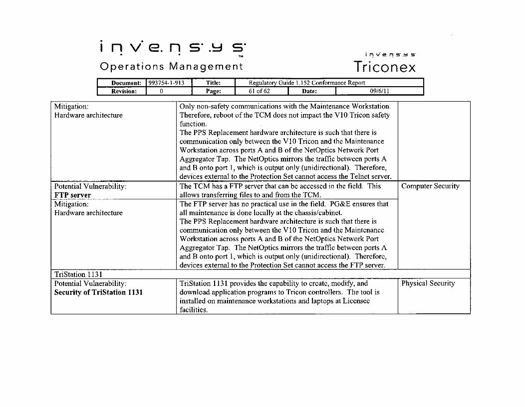
n v'e. n s. sTMOperations Management
inv'e. ns'.- s"
TriconexI Document: 1993754-1-913 I Title: I Regulatory Guide 1. 152 Conformance Report
Revision: 0 Page: 61 of 62 1 Date: I 09/6/11
Mitigation: Only non-safety communications with the Maintenance Workstation.Hardware architecture Therefore, reboot of the TCM does not impact the V 10 Tricon safety
function.The PPS Replacement hardware architecture is such that there iscommunication only between the V10 Tricon and the MaintenanceWorkstation across ports A and B of the NetOptics Network PortAggregator Tap. The NetOptics mirrors the traffic between ports Aand B onto port 1, which is output only (unidirectional). Therefore,devices external to the Protection Set cannot access the Telnet server.
Potential Vulnerability: The TCM has a FTP server that can be accessed in the field. This Computer SecurityFTP server allows transferring files to and from the TCM.Mitigation: The FTP server has no practical use in the field. PG&E ensures thatHardware architecture all maintenance is done locally at the chassis/cabinet.
The PPS Replacement hardware architecture is such that there iscommunication only between the V10 Tricon and the MaintenanceWorkstation across ports A and B of the NetOptics Network PortAggregator Tap. The NetOptics mirrors the traffic between ports Aand B onto port 1, which is output only (unidirectional). Therefore,devices external to the Protection Set cannot access the FTP server.
TriStation 1131
Potential Vulnerability: TriStation 1131 provides the capability to create, modify, and Physical SecuritySecurity of TriStation 1131 download application programs to Tricon controllers. The tool is
installed on maintenance workstations and laptops at Licenseefacilities.

i n v'e. n s"- s-TM
Operations Managementi nv'e.n s-.t s"
TriconexDocument: 1993754-1-913 I Title: I Regulatory Guide 1.152 Conformance ReportRevision: 0 Page: 62 of 62 1 Date: T 09/6/11
Mitigation:Administrative controls
During development Invensys Operations Management providephysical access controls to staged equipment to prevent unauthorizedchanges using TriStation 1131.After delivery to PG&E, administrative controls will be establishedprotect the TriStation 1131 engineering tool from unauthorized accessand inappropriate use.
Potential Vulnerability: TriStation 1131 projects are created with default username and Computer SecurityDefault username and password password at the highest level of privilege.Mitigation: Invensys Operations Management nuclear system integration projectPassword Management Policy controls assign passwords and access privileges that are dependent
upon work responsibilities.PG&E will manage TriStation passwords in accordance with the siteCyber Security Plan.
Potential Vulnerability: During download of an application program, the Tricon is placed into Computer SecurityMan-in-the-Middle during "PROGRAM" mode. The network connection is susceptible to Man-download in-the-Middle attack whereby malicious code could be installed.Mitigation: Hardware architecture of the PPS Replacement requires physical* Hardware architecture access to the V10 Tricon in order to download the application" Administrative controls program.
PG&E will establish administrative procedures that define thedownload process, including authorizing signatures. PG&E will alsoestablish controls over maintenance and test equipment to ensureapplication program downloads occur only from workstations andlaptops that have not been connected to unknown and unsecurednetworks.


![Picture2 - showa-gkn.ed.jp€¦ · 51 54 r Michio's Northern Dreams] [2010] 57 911 913 913 1959-). 913 gla 913 913 923 830](https://static.fdocuments.us/doc/165x107/5faa1942928f1e00e05212a5/picture2-showa-gknedjp-51-54-r-michios-northern-dreams-2010-57-911-913-913.jpg)


