990901EIS_RR_Instru.1 The Instrument: US Subsystems and Requirements Dr. Clarence M. Korendyke US...
30
0901EIS_RR_Instru.1 The Instrument: US Subsystems and Requirements Dr. Clarence M. Korendyke US Project Scientist Naval Research Laboratory 202-767-3144 e-mail: [email protected] Dr. Charles M. Brown EIS US Instrument Scientist Naval Research Laboratory 202-767-3578 e-mail: [email protected]
-
Upload
tracey-pearson -
Category
Documents
-
view
214 -
download
0
Transcript of 990901EIS_RR_Instru.1 The Instrument: US Subsystems and Requirements Dr. Clarence M. Korendyke US...
990901EIS_RR_Instru.1
The Instrument: US Subsystems and Requirements
Dr. Clarence M. Korendyke
US Project Scientist
Naval Research Laboratory
202-767-3144
e-mail: [email protected]
Dr. Charles M. Brown
EIS US Instrument Scientist
Naval Research Laboratory
202-767-3578
e-mail: [email protected]
990901EIS_RR_Instru.2
Plan View
Elevation
EIS Optical-Mechanical Layout
990901EIS_RR_Instru.3
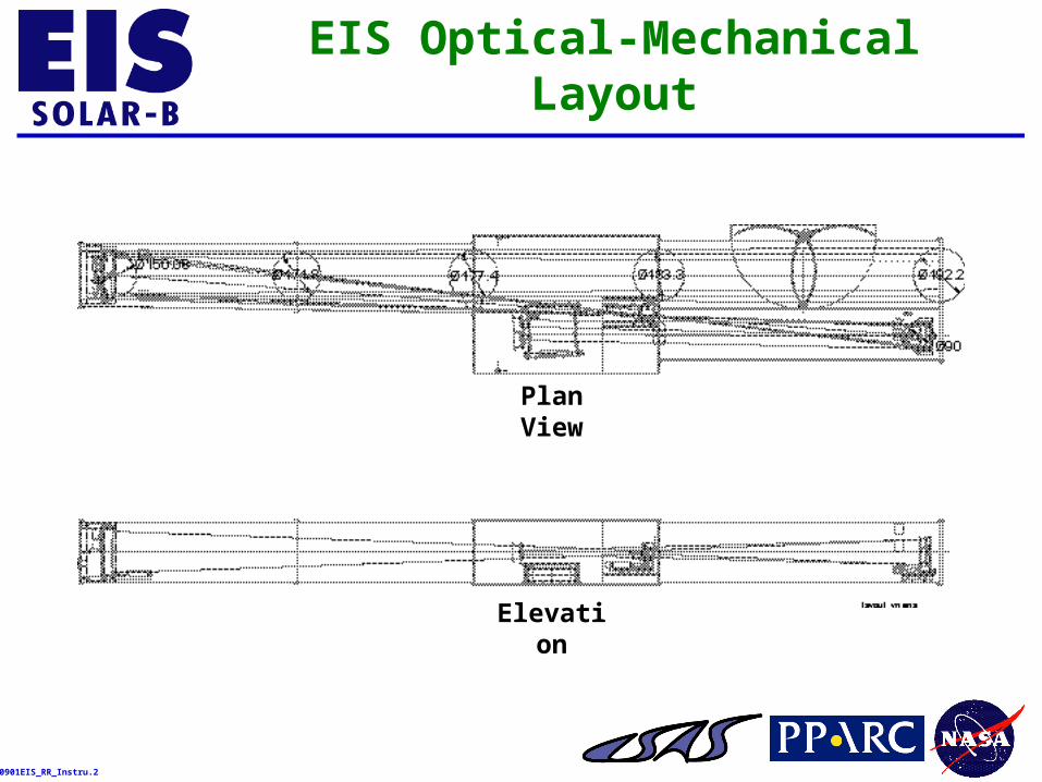
MIR/SLA/GRA Electrical Interfaces
MechanismSubassembly
Translation Actuator Encoder Average DutyCycle
Peak InternalPower
AveragePower
CoarsePosition
Size 16, 4phase stepper
motors
Resolver 2 (20 sec)operations per
day
10 W 0.0046 WMIRPrimary MirrorSubassembly
Fine Position PiezoelectricTransducer
Strain gauge 0.5V step perfive seconds
0.29 W <0.05 W
Slit/SlotExchange
Size 12, 4phase stepper
motors
Resolver 2 operationsper hour
3 W 0.0042 WSLASlit/Slot
SubassemblyShutter Brushless DC
motorOpticalencoder
1 operationevery 5seconds
2.65 W 0.0122 W
GRAGrating
Subassembly
FocusMechanism
Size 16, 4phase stepper
motors
OpticalEncoder
2 (20 sec)operations per
month
10 W 0.0046 W
NOTE: Duty cycle, peak internal power, and average dissipated power values are preliminary estimates.
990901EIS_RR_Instru.4
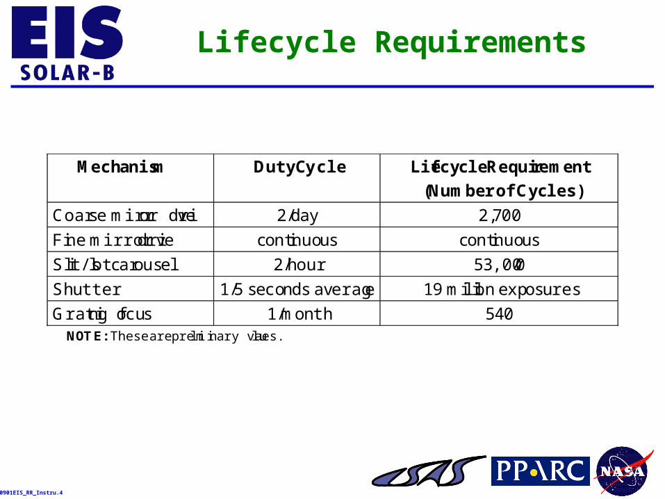
Lifecycle Requirements
Mechanism Duty Cycle Lifecycle Requirement
(Number of Cycles)
Coarse mirror drive 2/day 2,700
Fine mirror drive continuous continuous
Slit/slot carousel 2/hour 53,000
Shutter 1/5 seconds average 19 million exposures
Grating focus 1/month 540NOTE: These are preliminary values.
990901EIS_RR_Instru.5
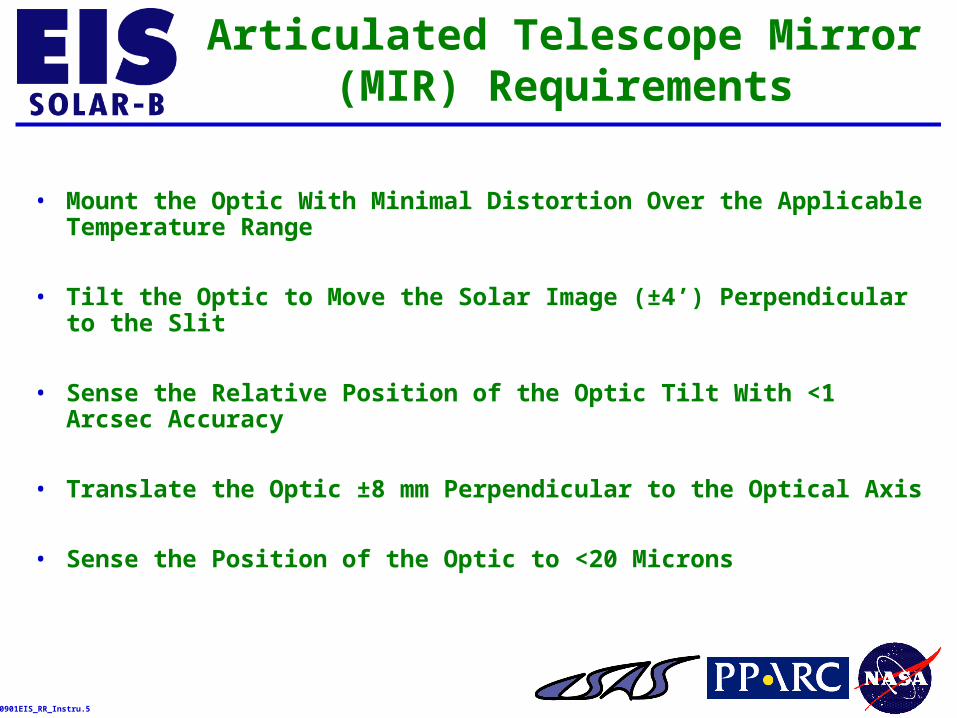
Articulated Telescope Mirror (MIR) Requirements
• Mount the Optic With Minimal Distortion Over the Applicable Temperature Range
• Tilt the Optic to Move the Solar Image (±4’) Perpendicular to the Slit
• Sense the Relative Position of the Optic Tilt With <1 Arcsec Accuracy
• Translate the Optic ±8 mm Perpendicular to the Optical Axis
• Sense the Position of the Optic to <20 Microns
990901EIS_RR_Instru.6
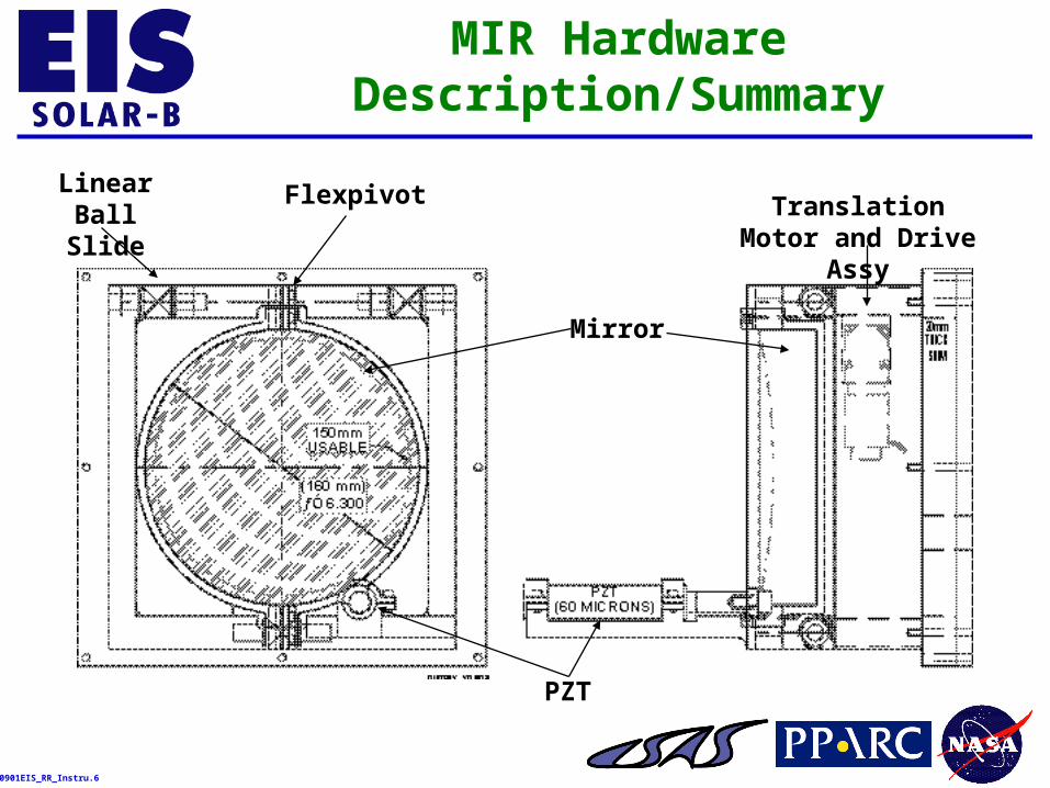
MIR Hardware Description/Summary
PZT
Mirror
Linear Ball Slide
Flexpivot Translation Motor and Drive Assy
990901EIS_RR_Instru.7
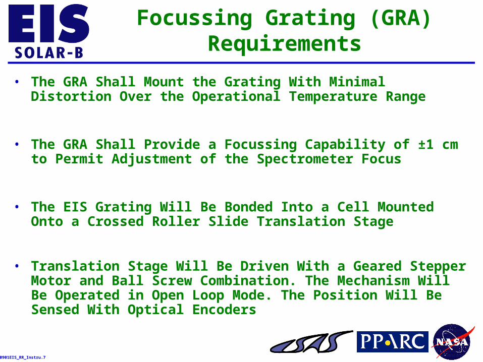
Focussing Grating (GRA) Requirements
• The GRA Shall Mount the Grating With Minimal Distortion Over the Operational Temperature Range
• The GRA Shall Provide a Focussing Capability of ±1 cm to Permit Adjustment of the Spectrometer Focus
• The EIS Grating Will Be Bonded Into a Cell Mounted Onto a Crossed Roller Slide Translation Stage
• Translation Stage Will Be Driven With a Geared Stepper Motor and Ball Screw Combination. The Mechanism Will Be Operated in Open Loop Mode. The Position Will Be Sensed With Optical Encoders

990901EIS_RR_Instru.8
GRA Hardware Description/Summary
Grating
Motor and Ball Screw Assy
Crossed Roller Bearing Slide
990901EIS_RR_Instru.9
Slit Assembly (SLA) Requirements
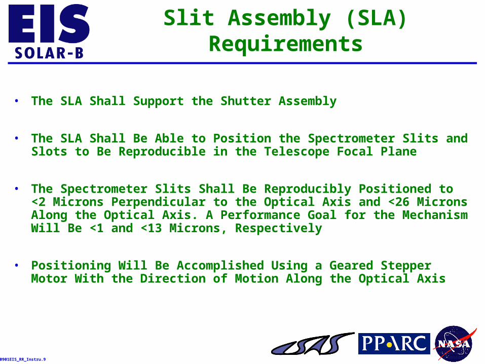
• The SLA Shall Support the Shutter Assembly
• The SLA Shall Be Able to Position the Spectrometer Slits and Slots to Be Reproducible in the Telescope Focal Plane
• The Spectrometer Slits Shall Be Reproducibly Positioned to <2 Microns Perpendicular to the Optical Axis and <26 Microns Along the Optical Axis. A Performance Goal for the Mechanism Will Be <1 and <13 Microns, Respectively
• Positioning Will Be Accomplished Using a Geared Stepper Motor With the Direction of Motion Along the Optical Axis
990901EIS_RR_Instru.10
Slit Assembly (SLA) Requirements (Continued)
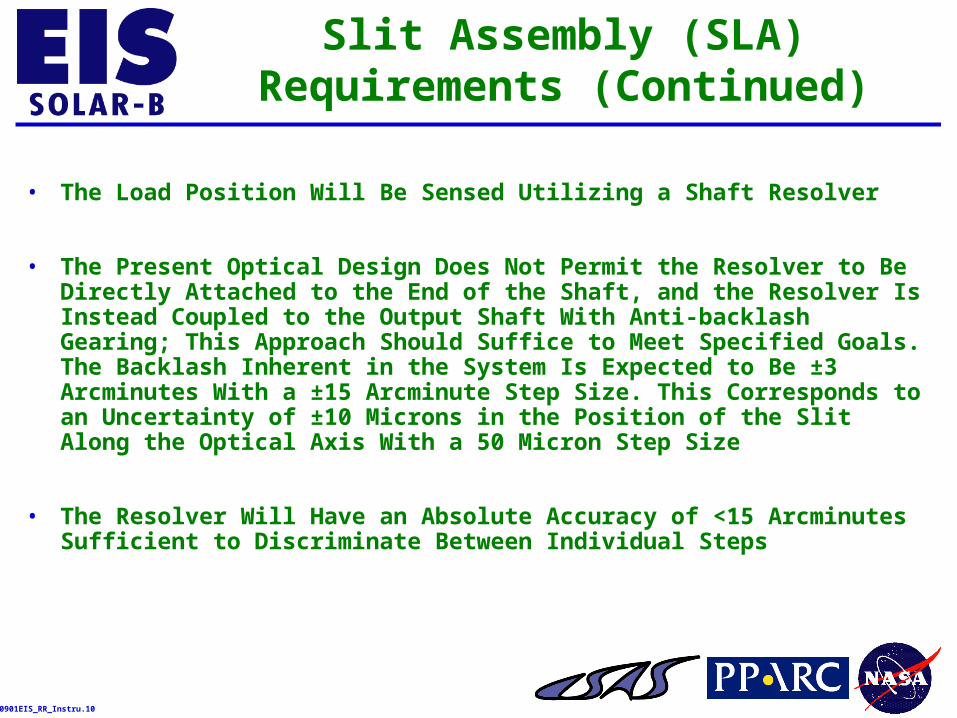
• The Load Position Will Be Sensed Utilizing a Shaft Resolver
• The Present Optical Design Does Not Permit the Resolver to Be Directly Attached to the End of the Shaft, and the Resolver Is Instead Coupled to the Output Shaft With Anti-backlash Gearing; This Approach Should Suffice to Meet Specified Goals. The Backlash Inherent in the System Is Expected to Be ±3 Arcminutes With a ±15 Arcminute Step Size. This Corresponds to an Uncertainty of ±10 Microns in the Position of the Slit Along the Optical Axis With a 50 Micron Step Size
• The Resolver Will Have an Absolute Accuracy of <15 Arcminutes Sufficient to Discriminate Between Individual Steps
990901EIS_RR_Instru.11
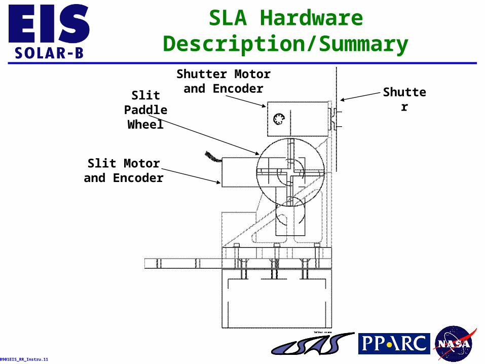
SLA Hardware Description/Summary
ShutterSlit Paddle Wheel
Slit Motorand Encoder
Shutter Motorand Encoder
990901EIS_RR_Instru.12
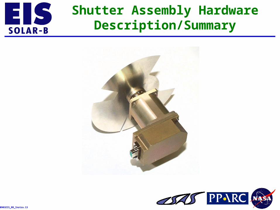
Shutter Mechanism Requirements
• The SLA Shall Include the EIS Instrument Shutter
• The Shutter Shall Be Able to Take a 50 ms Exposure
• <5% Photometric Error Over the Slit for These Short Exposures
990901EIS_RR_Instru.13
Shutter Assembly Hardware Description/Summary
990901EIS_RR_Instru.14
Requirements for the Filter Clamshell
• Vacuum Tight Enclosure
• P <1 Torr for Launch [TBD] 140 dB Acoustic Loads Expected
• Hold Time >1 Week [TBD]
• Reliable Calibrated Internal Pressure Sensor
• Clean
• Minimal Central Obstruction
• Pumpout/Backfill Valve With Filter and Throttle
• No Pressure Differential Allowed Front/Back (Air Passages)
• Sunshade for Filter Frame
• No Shock on Opening
• Vacuum Harness for Pre-Launch Ops
990901EIS_RR_Instru.15
Front Filter Assembly (FFA) Requirements
• A FFA Shall Be Provided to Block Heat and Visible Light From the EIS Instrument
• The FFA Shall Also Serve As a Bandpass Filter for the EUV Range of Interest
• The Filter Will Consist of a 1500 Å Thick Aluminum Film Mounted on a Nickel Mesh. The Aluminum May Be Coated With a Few Å of Carbon to Reduce Oxidation and to Improve Rejection of Light in Unwanted Solar Lines
• The FFA Will Provide a ±1% Transmittance Uniformity
• The FFA Shall Be Compatible With Ultra High Vacuum (UHV), and It Shall Provide the Necessary Mechanical Strength, and the Capability to Withstand Torr-Level Pressure Differentials
990901EIS_RR_Instru.16
Front Filter Assembly (FFA) Requirements (Continued)
• The Front Filter Will Be a ~200 mm Clear Aperture Diameter and It Will Be Segmented Into Four Quadrants, Each Separately Replaceable
• A Lightweight Aluminum Frame Shall Support the Mesh
• A Clamping Frame Shall Secure the Filters to the Clamshell Assembly. The Frames Will Be Designed to Minimize the Central Obstruction
990901EIS_RR_Instru.17
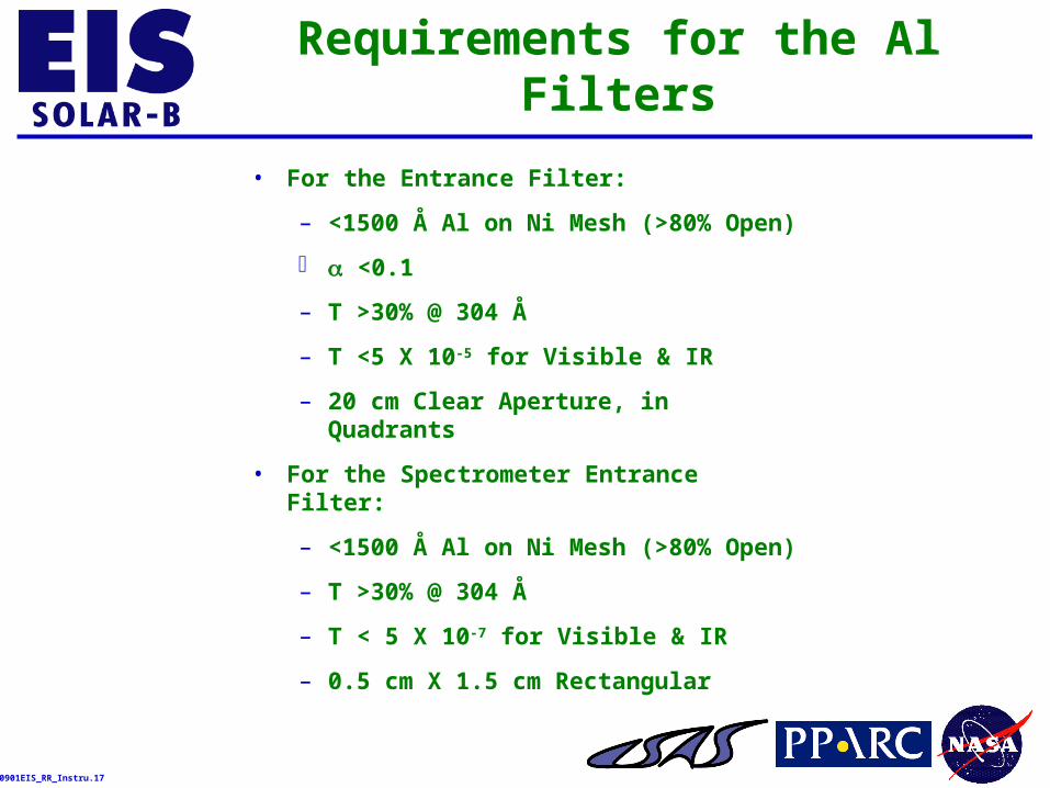
Requirements for the Al Filters
• For the Entrance Filter:
– <1500 Å Al on Ni Mesh (>80% Open)
<0.1
– T >30% @ 304 Å
– T <5 X 10⁻⁵ for Visible & IR
– 20 cm Clear Aperture, in Quadrants
• For the Spectrometer Entrance Filter:
– <1500 Å Al on Ni Mesh (>80% Open)
– T >30% @ 304 Å
– T < 5 X 10⁻⁷ for Visible & IR
– 0.5 cm X 1.5 cm Rectangular
990901EIS_RR_Instru.18
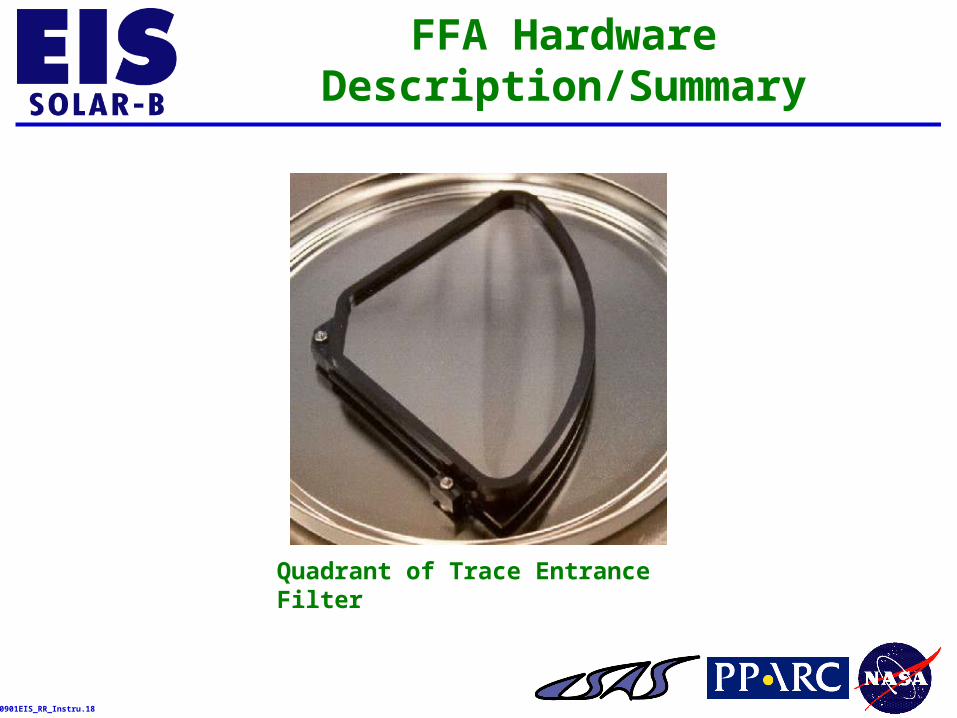
FFA Hardware Description/Summary
Quadrant of Trace Entrance Filter
990901EIS_RR_Instru.19
Spectrometer Entrance Filter (SEF) Requirements
• A Small Diameter Aluminum Filter Shall Be Provided to Mount Behind the EIS Spectrometer Slit
• The SEF Shall Provide Additional Reduction of the Visible Light Within the Spectrometer, Especially in the Event That the FFA Degrades Due to Orbital Debris and Micrometeorites
• The SEF Shall Have a Clear Aperture of ~20 mm. It Shall Be Placed Near the Slit, but Far Enough Away (>8 mm) That the Mesh Will Be Totally Out of Focus at the Detector
• Table 3-6 of the EIS Subsystems and Components Contract End Item Specification, EIS_Comp_Spec, Lists the Required Filter Properties
990901EIS_RR_Instru.20
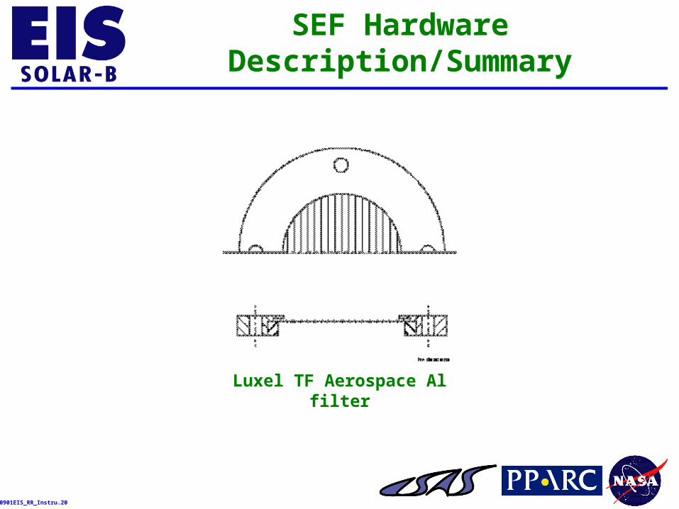
SEF Hardware Description/Summary
Luxel TF Aerospace Al filter
990901EIS_RR_Instru.21
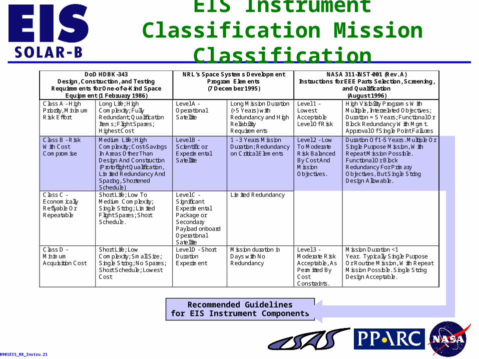
EIS Instrument Classification Mission Classification
DoD HDBK-343Design, Construction, and Testing
Requirements for One-of-a-Kind SpaceEquipment (1 February 1986)
NRL’s Space Systems DevelopmentProgram Elements(7 December 1995)
NASA 311-INST-001 (Rev. A)Instructions for EEE Parts Selection, Screening,
and Qualification(August 1996)
Class A - HighPriority, MinimumRisk Effort
Long Life; HighComplexity; FullyRedundant; QualificationItems; Flight Spares;Highest Cost
Level A -OperationalSatellite
Long Mission Duration(>5 Years) withRedundancy and HighReliabilityRequirements
Level 1 -LowestAcceptableLevel Of Risk
High Visibility Programs WithMultiple, Interrelated Objectives;Duration = 5 Years; Functional OrBlock Redundancy With Mgmt.Approval Of Single Point Failures
Class B - RiskWith CostCompromise
Medium Life; HighComplexity; Cost-SavingsIn Areas Other ThanDesign And Construction(Protoflight Qualification,Limited Redundancy AndSparing, ShortenedSchedule)
Level B -Scientific orExperimentalSatellite
1 - 3 Years MissionDuration; Redundancyon Critical Elements
Class C -EconomicallyReflyable OrRepeatable
Short Life; Low ToMedium Complexity;Single String; LimitedFlight Spares; ShortSchedule.
Level C -SignificantExperimentalPackage orSecondaryPayload onboardOperationalSatellite
Limited Redundancy
Level 2 - LowTo ModerateRisk BalancedBy Cost AndMissionObjectives.
Duration Of 1-5 Years. Multiple OrSingle Purpose Mission, WithRepeat Mission Possible.Functional Or BlockRedundancy For PrimaryObjectives, But Single StringDesign Allowable.
Class D -MinimumAcquisition Cost
Short Life; LowComplexity; Small Size;Single String; No Spares;Short Schedule; LowestCost
Level D - ShortDurationExperiment
Mission duration inDays with NoRedundancy
Level 3 -Moderate RiskAcceptable, AsPermitted ByCostConstraints.
Mission Duration <1Year. Typically Single PurposeOr Routine Mission, With RepeatMission Possible. Single StringDesign Acceptable.
Recommended Guidelinesfor EIS Instrument Components
990901EIS_RR_Instru.22
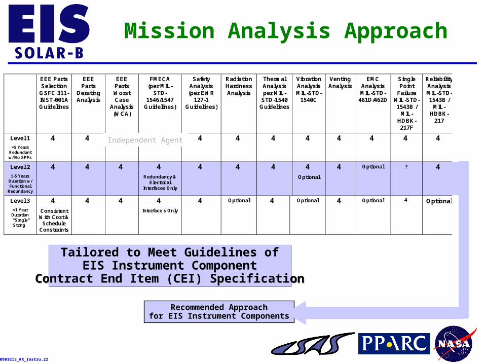
Mission Analysis Approach
EEE PartsSelection
GSFC 311-INST-001AGuidelines
EEEParts
DeratingAnalysis
EEEPartsWorstCase
Analysis(WCA)
FMECA(per MIL-
STD-1546/1547
Guidelines)
SafetyAnalysis(per EWR
127-1Guidelines)
RadiationHardnessAnalysis
ThermalAnalysisper MIL-
STD-1540Guidelines
VibrationAnalysisMIL-STD-
1540C
VentingAnalysis
EMCAnalysisMIL-STD-
461D/462D
SinglePoint
FailureMIL-STD-1543B /
MIL-HDBK-217F
ReliabilityAnalysisMIL-STD-1543B /
MIL-HDBK-
217
Level 1
=5 YearsRedundantw/ No SPFs
4 4 4 4 4 4 4 4 4 4 4 4
Level 2
1-5 YearsDuration w/Functional
Redundancy
4 4 4 4Redundancy &
ElectricalInterfaces Only
4 4 4 4Optional
4 Optional ? 4
Level 3
=1 YearDuration“SingleString”
4ConsistentWith Cost &Schedule
Constraints
4 4 4Interface s Only
4 Optional 4 Optional 4 Optional 4 Optional
Tailored to Meet Guidelines ofEIS Instrument Component
Contract End Item (CEI) Specification
Tailored to Meet Guidelines ofEIS Instrument Component
Contract End Item (CEI) Specification
Recommended Approachfor EIS Instrument Components
Independent Agent
990901EIS_RR_Instru.23
Safety, Reliability, and Quality Assurance (SR&QA) Requirements
• SR&QA and Verification Compliance Matrix (VCM) Requirements Defined in EIS Instrument Component CEI Specification (EIS_comp_spec)
• Configuration Management Plan uses MSFC MPG 8040.1Guidelines for Flight Models (DRD 874CM-001)
• Contamination Control & Implementation Plan in Consonance with UK’s EIS Instrument Requirements (DRD 872MP-001)
• Product Assurance Program for Flight Models Meets ISO 9000 Guidelines (DRD 872QE-001)
– Includes Preliminary/Final Hazard Analysis Inputs to UK’s EIS Instrument Safety Plan
– Includes Reliability Assurance and Parts/Materials/Processes Approach
• Verification Plan Defines Verification Approach, Structure, and Description (DRD 872VR-001)
990901EIS_RR_Instru.24
Other Factors
• Parts, Materials, and Processes (PMP) Selected to Assure Maximum Reliability and Performance in Space Environments
– Vacuum Stability via Total Mass Loss (TML) of >1.0% and Volatile Condensable Material (VCM) of >0.1% Per NRP-1124
– Traceability Achieved by Categorizing EEE Parts Into Sets Groups and Tracing Parts Through Fabrication, Assembly, Test, and Delivery
• Electrostatic Discharge (ESD) Control According to Processes Implementing MIL-STD-1686 Guidelines
• Closed-Loop Failure Reporting and Corrective Action System (FRACAS) for Failures Occurring During the Flight Model Acceptance Testing Phases
• Deliverable Shipping Container Compatible With the Anticipated Transportation Environmentals
• Documentation Uses Established Practices for Spaceflight Equipment
– Deliverable “As-built” Engineering Drawings for Flight Models
– Schematics, Assembly Drawings, Parts Lists, Test Procedures/Reports, and Calibration Data
990901EIS_RR_Instru.25
Project Planning and Control (1 of 3)
• During Phase B, the Following Management Tools (Delivery Dates) Will Be Developed to Allow Adequate Definition of the Hardware, Services, Materials, Subcontracts and Other Services of the Project:
– Configuration Management Plan (31 December 1999)
– EIS Component Specification Contract End Item (Updates A/R; Under Configuration Management)
– Preliminary Design Review Package (15 February 2000)
– Interface Control Documents (15 February 2000)
– Project Management Plan (31 December 1999)
– Monthly Progress Reports (Monthly)
990901EIS_RR_Instru.26
Project Planning and Control (2 of 3)
• Phase B Management Tools Continued:
– Financial Management Reports (Monthly)
– Work Breakdown Structure and Dictionary (30 November 1999)
– Risk Management Plan (31 December 1999)
– Contamination Control and Implementation Plan (15 February 2000)
– Product Assurance Plan (31 December 1999)
– System Error Budget (15 February 2000)
– Verification Plan (31 December 1999)
990901EIS_RR_Instru.27
Project Planning and Control (3 of 3)
• During Phase C/D, the Following Management Tools (Delivery Dates) Will Be Developed to Allow Adequate Definition of the Hardware, Services, Materials, Subcontracts and Other Services of the Project:
– All Management Tools Developed Under Phase B Shall Be Updated As Necessary
– Critical Design Review Package (15 February 2001)
– Pre-Environmental Review Package (15 February 2002)
– Flight Readiness Review Package (15 September 2002)
– Verification Test Report (15 September 2002)
990901EIS_RR_Instru.28
Product Assurance
• EIS Instrument Component Product Assurance Guidelines Shall Be Defined in the Product Assurance Plan Submitted During Phase B
• The Product Assurance Plan Shall Address:
– Safety: Implementation of Industrial and System Safety Throughout the Project Lifecycle
– Quality: Implementation of All Elements of the Quality Assurance Program Throughout the Lifecycle of the Project
– Reliability: Definition of the Procedures and Controls for Implementing the Programmatic Reliability and Maintainability Requirements
990901EIS_RR_Instru.29
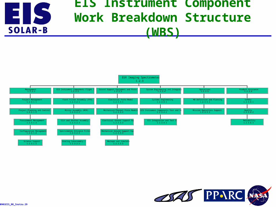
EIS Instrument Component Work Breakdown Structure (WBS)
Science Support1.2.3.1.5
Configuration Management1.2.3.1.4
Procurement Management1.2.3.1.3
Project Planning and Control1.2.3.1.2
Project Management1.2.3.1.1
Management1.2.3.1
Grating Subassembly (GRA)1.2.3.2.5
Spectrometer Entrance Filter (SEF)1.2.3.2.4
Slit and Shutter Assembly (SLA)1.2.3.2.3
Mirror Assembly (MIR)1.2.3.2.2
Front Filter Assembly (FFA)1.2.3.2.1
EIS Instrument Components Flight System1.2.3.2
Mockups and Simulators1.2.3.3.5
Mechanical Ground Support Equipment1.2.3.3.4
Electrical Ground Support Equipment1.2.3.3.3
Mechanical/Thermal Proto Models1.2.3.3.2
Electrical Proto Model1.2.3.3.1
Ground Support Equipment and Proto Models1.2.3.3
EIS Integration and Test Support1.2.3.4.3
EIS Instrument Components Test and Verification1.2.3.4.2
Systems Engineering1.2.3.4.1
System Engineering and Integration1.2.3.4
Mission Operations Support1.2.3.5.2
MO Definition and Planning1.2.3.5.1
Operations1.2.3.5
Reliability1.2.3.6.3
Quality1.2.3.6.2
Safety1.2.3.6.1
Product Assurance1.2.3.6
EUV Imaging Spectrometer1.2.3
990901EIS_RR_Instru.30
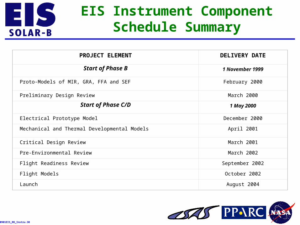
EIS Instrument Component Schedule Summary
PROJECT ELEMENT DELIVERY DATE
Start of Phase B 1 November 1999
Proto-Models of MIR, GRA, FFA and SEF February 2000
Preliminary Design Review March 2000
Start of Phase C/D 1 May 2000
Electrical Prototype Model December 2000
Mechanical and Thermal Developmental Models April 2001
Critical Design Review March 2001
Pre-Environmental Review March 2002
Flight Readiness Review September 2002
Flight Models October 2002
Launch August 2004