99 Washington Street Visit us at Data Sheet VIAVI T ...
22
VIAVI Solutions Platform Platform Requirements The mainframe shall be non modular The product shall be field upgradeable The test system shall utilize Linux operating system to ensure optimum stability Display The size of the display shall be 7 inches minimum, and 1200x600 type for best resolution The Test Set shall support a Screen Saver The Test Set shall support a mode that 'locks' the touchscreen for use without a password Power/Battery The Test Equipment must be battery operated The Test Equipment must have a built-in battery charger The battery must be field replaceable The equipment shall perform a 10G test for a minimum of 3 hours on battery power. Operating time Between 2 to 5 hours depending on the application Charging time Approximately 7 hours from empty Unit power input 12VDC, 60 Watt Max Power supply input 100 to 240 VAC, 50/60 Hz, auto-sensing Power supply output 12VDC, 5 AMP Max Industry Standards and Compliance CE Class A Compliant EMI/ESD: CE compliant, FCC part 15 subpart A Class A FCC Part 15 Compliant Physical and Environment Specifications Temperature range: • Operating, all options: 0°C to +50°C (+32°F to +122°F) • Storage: - 20°C to +60°C (-4°F to +140°F) Storage Humidity: 10-95% without condensing. Operating Humidity: 10-90% without condensing. Drop Test - Shock per IEC 68-2-27 and 68-2-29 Ed. 2.0 Drop Test - Durability per IEC 721-3-7 2nd Ed./IEC 61010-1 Vibration per IEC 68-2-6 and MIL-PRF-28800F (Class 2) Field Operation The Test Equipment shall be portable, battery operated and rugged for field operations. The Test Equipment must be protected by bumpers. Weight and Size The weight of the test set shall not be greater than 4.2 lbs/1.9kg while supporting up to 10G rates The size of the test set shall not be greater than 17.78 x 24.13 x 7.62cm (7”x9.5”x3”) while supporting up to 10G rates Operation The base unit shall be able to be turned on and operational in less than 2 minute The Test Equipment shall accept operations with an external keyboard. The unit will boot to a simplified launch page allowing the user to select previous test configurations and/or favorite test configurations. I/O’s The Test Equipment shall include the following I/O interfaces • VT100 (RJ-45) • 2 x USB • RJ-45 (Ethernet/IP) • Serial • Wifi (optional) • Bluetooth (optional) The Test Equipment shall be able to download data to PC or compatible device via standard interface or protocol: Data Sheet VIAVI T-BERD ® /MTS-5800 Specifications T-BERD®/MTS-5800 99 Washington Street Melrose, MA 02176 Phone 781-665-1400 Toll Free 1-800-517-8431 Visit us at www.TestEquipmentDepot.com
Transcript of 99 Washington Street Visit us at Data Sheet VIAVI T ...

VIAVI Solutions
Platform
Platform Requirements
The mainframe shall be non modular
The product shall be field upgradeable
The test system shall utilize Linux operating system to ensure optimum stability
Display
The size of the display shall be 7 inches minimum, and 1200x600 type for best resolution
The Test Set shall support a Screen Saver
The Test Set shall support a mode that 'locks' the touchscreen for use without a password
Power/Battery
The Test Equipment must be battery operated
The Test Equipment must have a built-in battery charger
The battery must be field replaceable
The equipment shall perform a 10G test for a minimum of 3 hours on battery power.
Operating time Between 2 to 5 hours depending on the application
Charging time Approximately 7 hours from empty
Unit power input 12VDC, 60 Watt Max
Power supply input 100 to 240 VAC, 50/60 Hz, auto-sensing
Power supply output 12VDC, 5 AMP Max
Industry Standards and Compliance
CE Class A Compliant
EMI/ESD: CE compliant, FCC part 15 subpart A Class A
FCC Part 15 Compliant
Physical and Environment Specifications
Temperature range:• Operating, all options: 0°C to +50°C
(+32°F to +122°F) • Storage: - 20°C to +60°C (-4°F to +140°F)
Storage Humidity: 10-95% without condensing.
Operating Humidity: 10-90% without condensing.
Drop Test - Shock
per IEC 68-2-27 and 68-2-29 Ed. 2.0
Drop Test - Durability
per IEC 721-3-7 2nd Ed./IEC 61010-1
Vibration
per IEC 68-2-6 and MIL-PRF-28800F (Class 2)
Field Operation
The Test Equipment shall be portable, battery operated and rugged for field operations.
The Test Equipment must be protected by bumpers.
Weight and Size
The weight of the test set shall not be greater than 4.2 lbs/1.9kg while supporting up to 10G rates
The size of the test set shall not be greater than 17.78 x 24.13 x 7.62cm (7”x9.5”x3”) while supporting up to 10G rates
Operation
The base unit shall be able to be turned on and operational in less than 2 minute
The Test Equipment shall accept operations with an external keyboard.
The unit will boot to a simplified launch page allowing the user to select previous test configurations and/or favorite test configurations.
I/O’s
The Test Equipment shall include the following I/O interfaces• VT100 (RJ-45)• 2 x USB• RJ-45 (Ethernet/IP)• Serial• Wifi (optional)• Bluetooth (optional)
The Test Equipment shall be able to download data to PC or compatible device via standard interface or protocol:
Data Sheet
VIAVI T-BERD®/MTS-5800Specifications
T-BERD®/MTS-5800
99 Washington Street Melrose, MA 02176 Phone 781-665-1400Toll Free 1-800-517-8431
Visit us at www.TestEquipmentDepot.com
2 VIAVI T-BERD/MTS-5800 Specifications
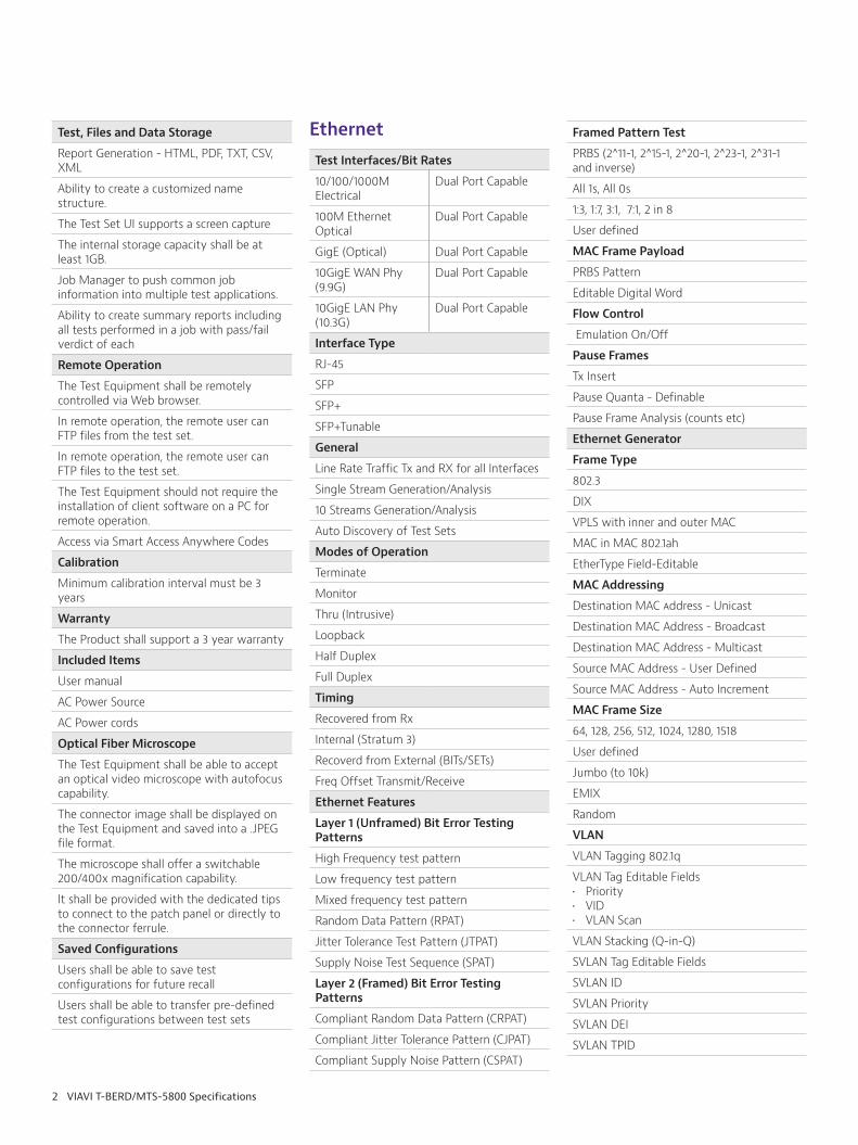
Ethernet
Test Interfaces/Bit Rates
10/100/1000M Electrical
Dual Port Capable
100M Ethernet Optical
Dual Port Capable
GigE (Optical) Dual Port Capable
10GigE WAN Phy (9.9G)
Dual Port Capable
10GigE LAN Phy (10.3G)
Dual Port Capable
Interface Type
RJ-45
SFP
SFP+
SFP+Tunable
General
Line Rate Traffic Tx and RX for all Interfaces
Single Stream Generation/Analysis
10 Streams Generation/Analysis
Auto Discovery of Test Sets
Modes of Operation
Terminate
Monitor
Thru (Intrusive)
Loopback
Half Duplex
Full Duplex
Timing
Recovered from Rx
Internal (Stratum 3)
Recoverd from External (BITs/SETs)
Freq Offset Transmit/Receive
Ethernet Features
Layer 1 (Unframed) Bit Error Testing Patterns
High Frequency test pattern
Low frequency test pattern
Mixed frequency test pattern
Random Data Pattern (RPAT)
Jitter Tolerance Test Pattern (JTPAT)
Supply Noise Test Sequence (SPAT)
Layer 2 (Framed) Bit Error Testing Patterns
Compliant Random Data Pattern (CRPAT)
Compliant Jitter Tolerance Pattern (CJPAT)
Compliant Supply Noise Pattern (CSPAT)
Framed Pattern Test
PRBS (2^11-1, 2^15-1, 2^20-1, 2^23-1, 2^31-1 and inverse)
All 1s, All 0s
1:3, 1:7, 3:1, 7:1, 2 in 8
User defined
MAC Frame Payload
PRBS Pattern
Editable Digital Word
Flow Control
Emulation On/Off
Pause Frames
Tx Insert
Pause Quanta - Definable
Pause Frame Analysis (counts etc)
Ethernet Generator
Frame Type
802.3
DIX
VPLS with inner and outer MAC
MAC in MAC 802.1ah
EtherType Field-Editable
MAC Addressing
Destination MAC Address - Unicast
Destination MAC Address - Broadcast
Destination MAC Address - Multicast
Source MAC Address - User Defined
Source MAC Address - Auto Increment
MAC Frame Size
64, 128, 256, 512, 1024, 1280, 1518
User defined
Jumbo (to 10k)
EMIX
Random
VLAN
VLAN Tagging 802.1q
VLAN Tag Editable Fields• Priority• VID• VLAN Scan
VLAN Stacking (Q-in-Q)
SVLAN Tag Editable Fields
SVLAN ID
SVLAN Priority
SVLAN DEI
SVLAN TPID
Test, Files and Data Storage
Report Generation - HTML, PDF, TXT, CSV, XML
Ability to create a customized name structure.
The Test Set UI supports a screen capture
The internal storage capacity shall be at least 1GB.
Job Manager to push common job information into multiple test applications.
Ability to create summary reports including all tests performed in a job with pass/fail verdict of each
Remote Operation
The Test Equipment shall be remotely controlled via Web browser.
In remote operation, the remote user can FTP files from the test set.
In remote operation, the remote user can FTP files to the test set.
The Test Equipment should not require the installation of client software on a PC for remote operation.
Access via Smart Access Anywhere Codes
Calibration
Minimum calibration interval must be 3 years
Warranty
The Product shall support a 3 year warranty
Included Items
User manual
AC Power Source
AC Power cords
Optical Fiber Microscope
The Test Equipment shall be able to accept an optical video microscope with autofocus capability.
The connector image shall be displayed on the Test Equipment and saved into a .JPEG file format.
The microscope shall offer a switchable 200/400x magnification capability.
It shall be provided with the dedicated tips to connect to the patch panel or directly to the connector ferrule.
Saved Configurations
Users shall be able to save test configurations for future recall
Users shall be able to transfer pre-defined test configurations between test sets

3 VIAVI T-BERD/MTS-5800 Specifications
CVLAN ID
CVLAN Priority
Supports up to 8 stacked VLAN Tags
VPLS
VPLS Parameters - MAC Addresses
VPLS Parameters - Frame Type
VPLS Parameters - EtherType
VPLS Tunnel and VC Label - Label, CoS, TTL
VPLS Control Word - Reserved Bits, Sequence Number
MAC in MAC/PBT/PBB
Parameters - MAC Address
B-Tag - TPI, VID, Priority, DEI
I-Tag - TPI, SID, Priority, DEI, NCA, Res1, Res2
MPLS
Single Label Support
Stacked Label Support - Up to 2
Editable Parameters/Results - Label
Editable Parameters/Results - CoS
Editable Parameters/Results - TTL
MPLS-TP
MPLS-TP Label Support (Tunnel and VC)
VLAN Tag Support
Linerate Traffic Generation
Traffic Analysis
Editable Parameters/Results - Label
Editable Parameters/Results - Priority
Editable Parameters/Results - TTL
Rx Filters
GAL (Label 13) + ACH from ITU-T G.8113.1• Common Header Label - PW, LSP, Section • CCM Generation and Analysis• LBM/LBR Generation and Analysis • AIS Generation and Analysis
OAM Alert Label (Label 14) from ITU-T G.8114• Common Header Label - PW, LSP, Section • CCM Generation and Analysis• LBM/LBR Generation and Analysis • AIS Generation and Analysis
OAM Alert Label (Label 14) from ITU-T Y.1711Common Header Label - PW, LSP, Section • CCM Generation and Analysis • FFD Generation and Analysis • BDI Generation and Analysis • FDI Generation and Analysis
Simultaneous OAM and background traffic generation
Ethernet OAM
Y.1731 Service OAM and 802.1ag CFM
CCM Messages
Programmable CCM Rate
CCM Type - Unicast, Multicast
MEG ID End Point
Maintenance Domain Level
AIS Tx/Rx
RDI Tx/Rx
LBR/LBM (Ping) - Unicast, Multicast
LTM/LTR (Trace)
MEP Discovery
802.3ah Link OAM
Mode - Passive/Active
Vendor OUI
Vendor Specific Info
Max PDU Size
Unidirectional Links
Remote Loopback
Link Events
Variable Retrieval
Dying Gasp
Link Fault
Critical Event
Errored Symbol Period Event
Errored Frame Event
Errored Frame Period Event
Errored Frame Second Summary Event
IP Packet Generator
IP
IPv4 Frame Format
IPv6 Frame Format
TCP Port Number
UDP Port Number
IP Addressing
Destination IP Address - User Defined
Source IP Address - User Defined
IPv4 Editable Fields
ToS
DSCP
Flags
Protocol
TTL
IPv6 Editable Fields
Traffic Class
Flow Label
Next Header
Hop Limit
IP Ping
Fast Ping
IP TraceRoute
Traffic Generator
Number of Traffic Engines
Bandwidth Controlled
Bandwidth Specification in Mbps or kbps
Bandwidth Granularity
Bandwidth Specification in %
Bandwidth Utilization Accuracy - 0.1%
Burst Mode - Burst Size - 1 to 2M frames
Bandwidth Specified - Definable
Continuous Tx
Once Tx - Definable frames/burst
Traffic generation in LBM frames at line rate
Analysis of LBR frames at line rate
Traffic Profiles
Constant B/W
Ramp B/W
Bursty B/W
Flood B/W
Traffic generation in Mbps, kbps, or % utilization
B/W configurable based on L1 or L2
TCP Throughput
10/100/1000M Linerate Stateful Emulation
1GigE Linerate Stateful Emulation
10GigE Linerate Stateful Emulation
Configurable Src and Dest IP address
Packet length
TCP/UDP Traffic Modes
Source Port
Destination Port
Listen Port
Configurable TCP Window Size
Measures TCP Efficiency
Measures Buffer Delay
TCP Client Emulation
TCP Server Emulation

4 VIAVI T-BERD/MTS-5800 Specifications
Up to 64 TCP Stateful Sessions Simultaneously
Supports 4 Background Streams
Compatible with IPERF
RFC 2544
Asymmetric Testing
Symmetric Testing
Throughput
Frame Loss
Out of sequence frames
Errored Frames
Delay
Back to Back
Committed Burst Size (CBS)
Policer Test
Jitter
Master/Slave
Pass/Fail Thresholds per MEF 23.1
Connectivity QuickCheck
Parallel Testing
Optional Testing with line rate LBM frames
Definable Frame Size
LAG Support• Sequential MAC Addresses• Suppression of OOS Frames
Report formats
Graphical Results
Total Test Time Display
One Way Delay with GPS or CDMA receiver
ITU-T Y.1564
10 Traffic Streams
Service Configuration Test
Service Performance Test
Committed Information Rate (CIR)
Extended IR (EIR)
Maximum IR (MIR)
Frame Loss Rate (FLR)
Frame Delay (FD)
Frame Delay Variation
Committed Burst Size (CBS)
Policer Test
Round Trip Testing
Concurrent Bi-directional Testing
Configurable VLAN, Priority, Addressing and Pass/Fail Thresholds
Programmable Pass/Fail Thresholds
Graphical Results
Screenshot support
Auto-Negotiation Check
Saved Test Profiles
Saved Reports
Configurable DEI, TPID, TOS/DSCP
Inclusive of L2 Ethernet, IPv4, and IPv6
Integrated TrueSpeed TCP traffic stream with background streams
Optional Testing with line rate LBM frames
Asymmetric Testing
LAG support• Sequential MAC Addresses• Suppression of OOS Frames
One Way Delay with GPS or CDMA receiver
IETF RFC 6349
Supported on 10/100/1000 M Electrical and 1/10 G Optical Interfaces
Automated TCP Throughput test per RFC 6349
Path MTU Detection Test
Round Trip Time Test
Walk the Window Test
TCP Throughput Test
Traffic Shaping Test
TCP Efficiency Metric
Buffer Delay Metric
Up to 64 TCP Stateful Sessions Simultaneously
1 KB TCP Window Size Granularity
Jumbo Frame Support
Graphical Results and Report Generation
Configurable File Sizes and Window Sizes
Total Test Time Display
Configurable Saturation Window Test
Compatible with the following endpoints: • T-BERD/MTS instruments• QT-600 Ethernet Probes • TrueSpeed VNF Server
Layer 2 Transparency Testing
Send/Receive Ethernet Control Plane Traffic
Encapsulation supported• VLAN• Q-in-Q• Spanning Tree• Cisco Protocols (Discovery etc.)• GARP• STP
Send/Receive Ethernet Control Plane Traffic• Spanning Tree Frames Tx/Rx• Cisco Discovery Protocol• LDP Frames Tx/Rx• Link Aggregation LACP• Cisco UDLD, ISL, PagP, DTP, PVST-PVST+• MAC Bridging 802.1d• VLAN-BRDGSTP• Custom Frame Builder
Synchronous Ethernet
1GE and 10GigE Tx/Rx
1000M/100M/10M Electrical Tx/Rx
100M/1000M Optical Tx/Rx
G.826x Compliant
Frequency offsets ± 100 ppm in 1 or 10 ppm increments
Recovered Interface Timing
4.6ppm Frequency Accuracy
SSM Message Decode
ESMC Message Transmit & Capture
Quality Message Decode
Definable SSM PDU Rate (pps)
Background Dataplane traffic generation
IEEE 1588v2 PTP
1GE and 10G Tx/Rx
1588v2 Master Emulation
1588v2 Slave Emulation
1G Dual Monitor
Encapsulations supported
None, VLAN, and Q-in-Q
Packet Delay Variation Measurements on Control Plane Traffic
Generate up to 4 streams of Background Dataplane traffic
Frame/Packet Capture and Decode via Wireshark
Layer 2 1588v2 Messaging
Layer 4 1588v2 Messaging
Message rates Multicast: Fastest = 16/128/8 (Announce/Sync/Delay); Slowest = one message every 16 seconds
Message rates Unicast: Fastest = 16/128/8 (Announce/Sync/Delay); Slowest = one message every 16 seconds
Support for Unicast and Multicast Address Mode
Support for Forwardable and Non-forwardable Address
Static Unicast message negotiation: ON or OFF
Thresholds for Sync and Delay PDV and FPP (Floor Packet Processing)
5 VIAVI T-BERD/MTS-5800 Specifications
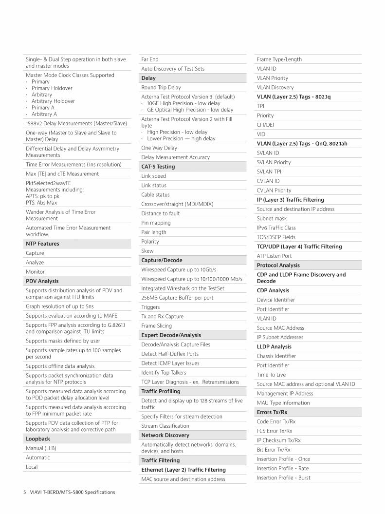
Single- & Dual Step operation in both slave and master modes
Master Mode Clock Classes Supported• Primary• Primary Holdover • Arbitrary• Arbitrary Holdover• Primary A• Arbitrary A
1588v2 Delay Measurements (Master/Slave)
One-way (Master to Slave and Slave to Master) Delay
Differential Delay and Delay Asymmetry Measurements
Time Error Measurements (1ns resolution)
Max |TE| and cTE Measurement
PktSelected2wayTE Measurements including:APTS: pk to pkPTS: Abs Max
Wander Analysis of Time Error Measurement
Automated Time Error Measurement workflow.
NTP Features
Capture
Analyze
Monitor
PDV Analysis
Supports distribution analysis of PDV and comparison against ITU limits
Graph resolution of up to 5ns
Supports evaluation according to MAFE
Supports FPP analysis according to G.8261.1 and comparison against ITU limits
Supports masks defined by user
Supports sample rates up to 100 samples per second
Supports offline data analysis
Supports packet synchronization data analysis for NTP protocols
Supports measured data analysis according to PDD packet delay allocation level
Supports measured data analysis according to FPP minimum packet rate
Supports PDV data collection of PTP for laboratory analysis and corrective path
Loopback
Manual (LLB)
Automatic
Local
Far End
Auto Discovery of Test Sets
Delay
Round Trip Delay
Acterna Test Protocol Version 3 (default)• 10GE High Precision - low delay • GE Optical High Precision - low delay
Acterna Test Protocol Version 2 with Fill byte• High Precision - low delay• Lower Precision — high delay
One Way Delay
Delay Measurement Accuracy
CAT-5 Testing
Link speed
Link status
Cable status
Crossover/straight (MDI/MDIX)
Distance to fault
Pin mapping
Pair length
Polarity
Skew
Capture/Decode
Wirespeed Capture up to 10Gb/s
Wirespeed Capture up to 10/100/1000 Mb/s
Integrated Wireshark on the TestSet
256MB Capture Buffer per port
Triggers
Tx and Rx Capture
Frame Slicing
Expert Decode/Analysis
Decode/Analysis Capture Files
Detect Half-Duflex Ports
Detect ICMP Layer Issues
Identify Top Talkers
TCP Layer Diagnosis - ex. Retransmissions
Traffic Profiling
Detect and display up to 128 streams of live traffic
Specify Filters for stream detection
Stream Classification
Network Discovery
Automatically detect networks, domains, devices, and hosts
Traffic Filtering
Ethernet (Layer 2) Traffic Filtering
MAC source and destination address
Frame Type/Length
VLAN ID
VLAN Priority
VLAN Discovery
VLAN (Layer 2.5) Tags - 802.1q
TPI
Priority
CFI/DEI
VID
VLAN (Layer 2.5) Tags - QnQ, 802.1ah
SVLAN ID
SVLAN Priority
SVLAN TPI
CVLAN ID
CVLAN Priority
IP (Layer 3) Traffic Filtering
Source and destination IP address
Subnet mask
IPv6 Traffic Class
TOS/DSCP Fields
TCP/UDP (Layer 4) Traffic Filtering
ATP Listen Port
Protocol Analysis
CDP and LLDP Frame Discovery and Decode
CDP Analysis
Device Identifier
Port Identifier
VLAN ID
Source MAC Address
IP Subnet Addresses
LLDP Analysis
Chassis Identifier
Port Identifier
Time To Live
Source MAC address and optional VLAN ID
Management IP Address
MAU Type Information
Errors Tx/Rx
Code Error Tx/Rx
FCS Error Tx/Rx
IP Checksum Tx/Rx
Bit Error Tx/Rx
Insertion Profile - Once
Insertion Profile - Rate
Insertion Profile - Burst
6 VIAVI T-BERD/MTS-5800 Specifications
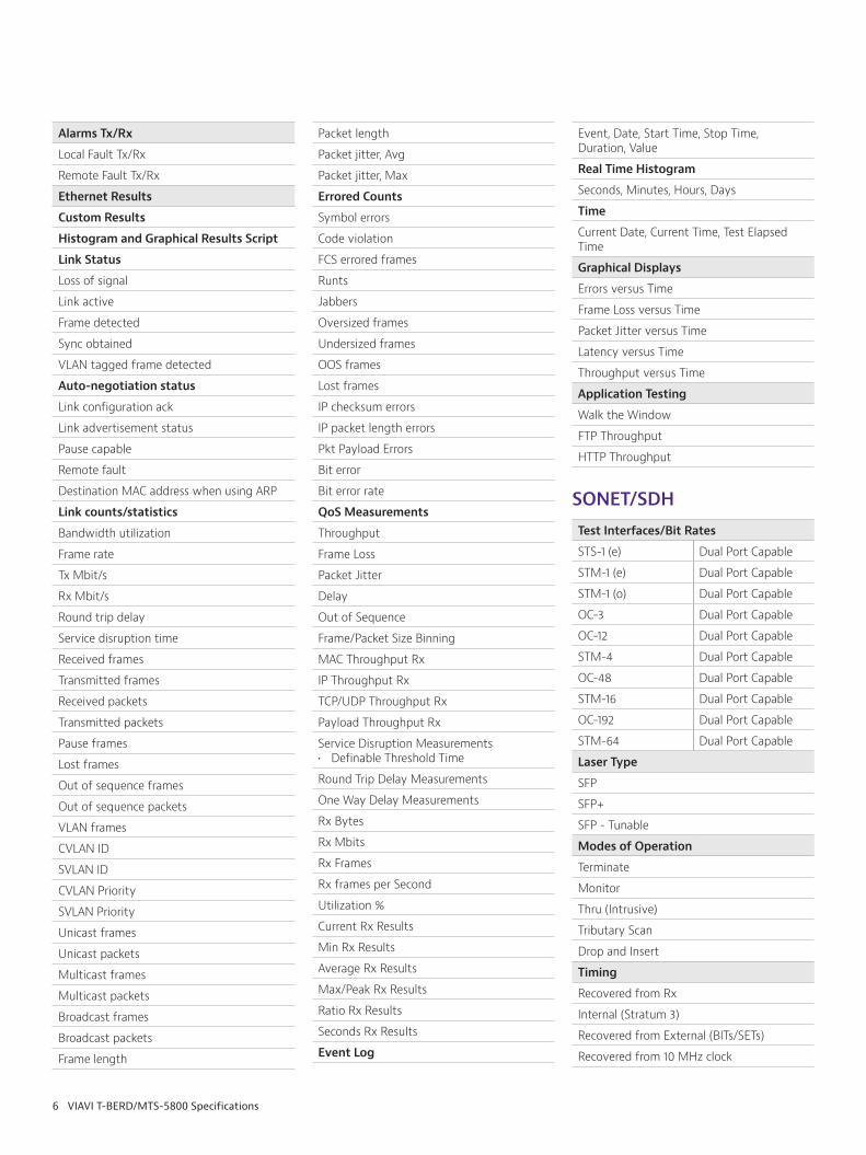
Alarms Tx/Rx
Local Fault Tx/Rx
Remote Fault Tx/Rx
Ethernet Results
Custom Results
Histogram and Graphical Results Script
Link Status
Loss of signal
Link active
Frame detected
Sync obtained
VLAN tagged frame detected
Auto-negotiation status
Link configuration ack
Link advertisement status
Pause capable
Remote fault
Destination MAC address when using ARP
Link counts/statistics
Bandwidth utilization
Frame rate
Tx Mbit/s
Rx Mbit/s
Round trip delay
Service disruption time
Received frames
Transmitted frames
Received packets
Transmitted packets
Pause frames
Lost frames
Out of sequence frames
Out of sequence packets
VLAN frames
CVLAN ID
SVLAN ID
CVLAN Priority
SVLAN Priority
Unicast frames
Unicast packets
Multicast frames
Multicast packets
Broadcast frames
Broadcast packets
Frame length
Packet length
Packet jitter, Avg
Packet jitter, Max
Errored Counts
Symbol errors
Code violation
FCS errored frames
Runts
Jabbers
Oversized frames
Undersized frames
OOS frames
Lost frames
IP checksum errors
IP packet length errors
Pkt Payload Errors
Bit error
Bit error rate
QoS Measurements
Throughput
Frame Loss
Packet Jitter
Delay
Out of Sequence
Frame/Packet Size Binning
MAC Throughput Rx
IP Throughput Rx
TCP/UDP Throughput Rx
Payload Throughput Rx
Service Disruption Measurements• Definable Threshold Time
Round Trip Delay Measurements
One Way Delay Measurements
Rx Bytes
Rx Mbits
Rx Frames
Rx frames per Second
Utilization %
Current Rx Results
Min Rx Results
Average Rx Results
Max/Peak Rx Results
Ratio Rx Results
Seconds Rx Results
Event Log
Event, Date, Start Time, Stop Time, Duration, Value
Real Time Histogram
Seconds, Minutes, Hours, Days
Time
Current Date, Current Time, Test Elapsed Time
Graphical Displays
Errors versus Time
Frame Loss versus Time
Packet Jitter versus Time
Latency versus Time
Throughput versus Time
Application Testing
Walk the Window
FTP Throughput
HTTP Throughput
SONET/SDH
Test Interfaces/Bit Rates
STS-1 (e) Dual Port Capable
STM-1 (e) Dual Port Capable
STM-1 (o) Dual Port Capable
OC-3 Dual Port Capable
OC-12 Dual Port Capable
STM-4 Dual Port Capable
OC-48 Dual Port Capable
STM-16 Dual Port Capable
OC-192 Dual Port Capable
STM-64 Dual Port Capable
Laser Type
SFP
SFP+
SFP - Tunable
Modes of Operation
Terminate
Monitor
Thru (Intrusive)
Tributary Scan
Drop and Insert
Timing
Recovered from Rx
Internal (Stratum 3)
Recovered from External (BITs/SETs)
Recovered from 10 MHz clock

7 VIAVI T-BERD/MTS-5800 Specifications
SONET/SDH Features
SONET/SDH Framing
Overhead Manipulation/Analysis
Optical/Electrical Power Level
PRBS Generation
PM/SM TTI messages Tx/Rx
Overhead Byte Viewing/Manipulation
Service Disruption Measurements• SD Separation/Debounce Time Setting• SD Threshold Time Settings
Signal Label generation/display
Freq Offset Transmit/Receive
Round Trip Delay Measurement
RTD Measurement Accuracy
PRBS Patterns
215-1, 215-1 Inverse
2^20-1, 2^20-1 Inverse
2^23-1, 2^23-1 Inverse
2^31-1, 2^31-1 Inverse
Programmable - 32 bit
ANSI and ITU implementations
Anomaly/Error generation
Bit/TSE
Frame Word
B1
B2
B3
HP-REI
MS-REI, LP-BIP
LP-REI
Insert - Single
Insert - Rate
Multiple
Defects/Alarms Generation/Analysis
LOS
LOF
RS-TIM
MS-AIS
MS-RDI
AU-LOP
AU-AIS
HP-UNEQ
HP-RDI
HP-TIM
HP-PLM
TU-LOP
TU-AIS
TU-LOM
LP-UNEQ
LP-RDI
LP-TIM
LP-PLM
LP-RFI
SDH Mappings
VC4 Bulk, AU-4-4c, AU-4-16c, AU-4-64c
VC12
VC4
VC3
E4
DS3
E3
E1
SONET Mappings
STS-1, STS-3c, STS-12c, STS-48c, STS-192c
VT1.5
DS3
DS1
E1
Results
Signal Category
Signal Present
Signal Loss Count
Signal Loss Seconds
Receive Frequency
Receive Frequency Deviation
Receive Frequency Maximum Deviation
Transmit Frequency
Electrical Input Level STS-1 STM-1e
dBdsx, dBm, voltsdBnom only
BPV Count (STS-1 only)
BPV-Error Rate (STS-1 only)
Regenerator/Section OH Category
FAS/Frame Word Error Count
FAS/Frame Word Error Rate
LOF Count
OOF Count
B1-BIP error Count
B1-BIP Error Rate
Severely Errored Seconds
OOF Seconds
Section Trace Mismatch
TIM
J0-Regenerator Trace
Multiplexer/Line OH Category
APS Message Count
APS Bridge Request Code
Ring
APS Destination Node
Ring
APS Source Node Ring
APS Path Code Ring
APS Status Ring
APS Request Code Linear
APS K1 Channel Number
Linear
APS K2 Channel Number
Linear
APS MSP Architecture
Linear
APS Status Linear
B2-BIP Error Count
B2-BIP Error Rate
SES
Unavailable Seconds
AIS Seconds
REI Count
REI Rate
S1 Synchronization Message
Z1 Byte Value
High Path (AU, VC3/4) OH Category
Pointer Justification Count
Pointer Increment Count
Pointer Decrement Count
Pointer NDF Count
Pointer Value
Pointer Size SS Bits
LOP Count
B3 (BIP) Error Count
B3 (BIP) Error Rate
B3 (BIP) Errored Seconds
REI Count
VC-3/4 REI Rate
POH SES
POH Unavailable Seconds
Signal Label C2
J1 Trace Message
Path Status G1

8 VIAVI T-BERD/MTS-5800 Specifications
Low Path (VC3/12, TU3/12, VT1.5) Category
Pointer Transmitted
Pointer Received
Pointer Just Count
Pointer Increment Count
Pointer Dec Count
Pointer NDF Count
LOP Count
LOP Seconds
B3/V5 BIP Count
B3/V5 BIP Error Rate
REI Count
Pointer Transmitted
Pointer Received
Signal Label C2/V5
Signal Label Mismatch
J2-Lower Order Trace Message
J2 Lower Order TIM
Logic Category
Pattern loss Count
Bit Error/TSE Count
Bit Error/TSE Rate
Pattern Slip Count
Pattern Slip Secs
Pattern Loss Count
Pattern Synchronization Loss Secs
Pattern Synchronization Status
Alarms
Signal Loss Status
Frame Synchronization Loss Status
Pattern Synchronization Loss Status
MS/Line-AIS
AIS (HP)
AIS (LP)
LOP (HP)
LOP (LP)
LOS
OOF
LOF
MS/Line RDI
LP RDI
HP RDI
MS/Line-REI
Regenerator Trace Identifier Mismatch
TIM
High Path Trace Identifier Mismatch
TIM
HP-UNEQ/UNEQ-P
Low Path Trace Identifier Mismatch
TIM
Loss of Multiframe TU-12, TU-3, VT-1.5
Overhead Byte Manipulation/Viewing – High Path
A1, A2, J0, J1, D1, D2, D3, C2, H1, H2, H3, G1, B2, K1, K2, F2, D4, D5, D6, H4, D7, D8, D9, H4, D7, D8, D9, Z3/F3, D10, D11, D12, Z4/K3, S1, Z1, M1/Z2, E2, Z5/N1
SDH Low Order View (AU/VT)
V5, S2, N6, K4
SOH and POH Evaluation
Text decode of S and C bytes for the trace identifier. J0 display of 16-byte ASCII sequence. J1, J2 display of 16- or 64-byte ASCII sequence.
Tandem Connection Monitoring (TCM)
Analysis of the N1 and N2 bytes, Monitoring/Display of: AIS, ODI, RDI, OEI, REI, APId, incoming B3/Computed BIP Comparison, IEC, TC-UNEQ
Performance Measures
G.826 ISM/OOS
G.828 ISM/OOS
G.829 ISM/OOS
M.2101
T1.231
T1.514
K1/K2 Event Log
Date, Time, K1 Value, Code, Channel, K2, Bridge, MSP, Status
Event Log
Event, Date, Start Time, Stop Time, Duration, Value
Real Time Histogram
Seconds, Minutes, Hours, Days
Time
Current Date, Current Time, Test Elapsed Time
OTN G.709
Test Interfaces/Bit Rates
OTU1 (2.7G) Dual Port Capable
OTU2 (10.7G) Dual Port Capable
OTU1e (11.045G) Dual Port Capable
OTU2e (11.095G) Dual Port Capable
Laser Type
SFP
SFP+
SFP+ - Tunable
Modes of Operation
Terminate
Monitor
Monitor/Thru
OTN Layer
OTN/ODU Framing
ODU1 in ODU2 Multiplexing
ODU0 Multiplexing• ODU-0 Bulk BERT from an OTU-2• ODU-0 1-Gigabit Ethernet Layer 2 & IPv4
traffic from an OTU-2• ODU-0 Bulk BERT from an OTU-1• ODU-0 1-Gigabit Ethernet Layer 2 & IPv4
traffic from an OTU-1• ODUflex Bulk BERT from an OTU-2• ODUflex 1-Gigabit Ethernet Layer 2 from
and OTU-2• Generic Mapping Procedure (GMP)
supported• GFP-T encapsulation of Ethernet 8B/10B
PCS
GFP-T• CID• UPI
Overhead Manipulation/Analysis
Power Level
PM/SM TTI messages Tx/Rx
Overhead Manipulation/Analysis
Service Disruption Measurements• SD Separation/Debounce Time Setting• SD Threshold Time Settings
Payload Type (PT) Label generation/display
Transfer Delay
Freq Offset Transmit/Receive
PRBS Patterns
2^20-1, 2^20-1 Inverse
2^23-1, 2^23-1 Inverse
2^31-1, 2^31-1 Inverse
Programmable - 32 bit
ANSI and ITU implementations
Error Insertion Capability
Single, Rate
OTU Error Tx/Rx
FAS
MFAS
SM-BIP/BEI

9 VIAVI T-BERD/MTS-5800 Specifications
PM-BIP/BEI
FEC Uncorrectable
FEC Correctable
TCM1-6 BIP
TCM1-6 BEI
Bit Error
Code Word Errors (Corr/Incorrect)
OTU Alarm Tx/Rx
LOF
OOF
LOM
OOF
OOM
SM-IAE
SM-TIM
SM-BDI
SM-BIAE
PM-TIM
PM-BDI
FTFL Fwd Sig Fail
FTFL Fwd Sig Degr.
FTFL Bwd Sig Fail
FTFL Bwd Sig Degr
TCM1-6 IAE
TCM1-6 TIM
TCM 1-6 BDI
TCM1-6 BIAE
ODU Errors Tx/Rx
FAS
MFAS
PM BIP/BEI
TCM BIP/BEI
Bit Error
ODU Alarms Tx/Rx
LOF
OOF
LOM
OOM
AIS
OCI
LCK
PM-TIM
PM-BDI
FTFL
FTFL Fwd Sig Fail
FTFL Fwd Sig Degr.
FTFL Bwd Sig Fail
FTFL Bwd Sig Degr
TCM1-6 IAE
TCM1-6 TIM
TCM 1-6 BDI
TCM1-6 BIAE
OPU Errors/Alarms Tx/Rx
PT Label Mismatch
Client Loss
Bit Error
ODU Mappings
Bulk
ODU0
ODU1
ODU2
SDH Mappings
VC4 Bulk, AU-4-4c, AU-4-16c, AU-4-64c
VC4
VC3
SONET Mappings
STS-1, STS-3c, STS-12c, STS-48c, STS-192c
Ethernet Mappings
10GigE
1GigE
Results
LEDS
Signal Present
Frame Sync
Pattern Sync
LOS
LOF
LSS
Interface
Invalid Rx Signal Seconds
LOS Count
Optical Rx Level (dBm)
Reference Frequency
Round Trip Delay
Rx Frequency Max Deviation (ppm)
Rx Frequency (Hz)
Rx Frequency Deviation (ppm)
Signal Losses Count
Tx Clock Source
Tx Freq Max Deviation (ppm)
Tx Frequency (Hz)
Tx Frequency Deviation (ppm)
FEC
Uncorrected Word Errors
Uncorrected Word Error Rate
Corrected Word Errors
Correctable Word Errors
Corrected Word Errors Rate
Correctable Word Error Rate
Corrected Bit Errors
Corrected Bit Errors Rate
Correctable Bit Errors
Correctable Bit Error Rate
Framing
Frame Sync Loss Seconds
Frame Sync Losses
OOF Seconds Count
FAS Errors
FAS Error Rate
LOF
LOF Seconds
Multiframe Sync Loss Seconds
OOM Seconds Count
MFAS Errors
MFAS Error Rate
OTU
OTU-AIS
OTU AIS Seconds
SM-IAE
SM-IAE Seconds
SM-BIP Error Counts
SM-BIP Error Rate
SM-BDI Seconds
SM-BDI Count
SM-BIAE Seconds
SM-BIAE Count
SM-BEI Count
SM-BEI Error Rate
SM-TIM Count
SM-TIM Seconds
SM-SAPI
SM-DAPI
SM-Operator Specific
GCC BERT Bits
GCC BERT Bit Errors

10 VIAVI T-BERD/MTS-5800 Specifications
GCC BERT Bit Error Rate
ODU
ODU-AIS
ODU-AIS Seconds
ODU-LCK
ODU-LCK Seconds
ODU-OCI
ODU-OCI Seconds
PM-BIP Count
PM BIP Error Rate
PM-BDI Seconds
PM-BDI Count
PM-BEI Count
PM-BEI Error Rate
PM-TIM Seconds
PM-TIM Count
PM-SAPI
PM-DAPI
PM-Operator Specific
PM Round Tip Delay Recent
PM Round Trip Delay Last
FTFL
Forward-Fault Type
Forward-SF Seconds
Forward-Operator Specific
Forward-Operator Identifier
Backward-Fault Type
Backward-SF Seconds Count
Backward-SD Seconds Count
Backward-Operator Identifier
Backward-Operator Specific
TCM 1-6
IAE Seconds
BIP Errors
BIP Error Rate
BDI Seconds
BIAE Seconds
BEI Errors
BEI Error Rate
TIM Seconds
SAPI
DAPI
Operator Specific
GCC BERT Bits
GCC BERT Bit Errors
GCC BERT Bit Error Rate
OPU
Payload Type Mismatch Seconds
Payload Type
Payload
Pattern Sync Loss Seconds
Pattern Sync Losses
TSE/Bit Errors
TSE/Bit Error Rate
Ethernet Client
As per Ethernet results
RFC 2544 on 10 GE client
SONET/SDH Client
As per SONET/SDH results
OTN Check
Automated workflow is available at all OTN rates for OTN Bulk
Set test duration based on Bit Error Rate Theory or actual time
Bit Error Rate Theory parameters for test duration:• Data Rate (e.g. OTU4)• BER Threshold• Confidence Level (% value)
Key automated tests
Payload BERT• PRBS pattern selection• Pass/Fail BER Threshold
Round Trip Delay• Selection of applicable OH fields: PM,
TCM1-6• Measurement Frequency• Pass/Fail Threshold (ms)
GCC Transparency• Selection of applicable OH field: GCC0,
GCC1 or GCC2• Pass/Fail BER Threshold
Report generation and formats
Fibre Channel
Laser Type
SFP
SFP+
Modes of Operation
Terminate
Monitor
Thru
Test Interfaces/Bit Rates
1.0625 Gbit/s Dual Port Capable
2.125 Gbit/s Dual Port Capable
4.25 Gbit/s Dual Port Capable
8.5 Gbit/s Dual Port Capable
10.519 Gbit/s Dual Port Capable
14.025 Gbit/s Dual Port Capable
Fibre Channel Features
General
Flow Control
Login
Buffer Credits
Fibre Channel Login
at “F-Port”
at “N-Port”
Layer 1 (Unframed) Bit Error Testing Patterns
High frequency test pattern
Low frequency test pattern
Mixed frequency test pattern
Random Data Pattern (RPAT)
Jitter Tolerance Test Pattern (JTPAT)
Supply Noise Test Sequence (SPAT)
Layer 2 (Framed) Bit Error Testing Patterns
Compliant Random Data Pattern (CRPAT)
Compliant Jitter Tolerance Pattern (CJPAT)
Compliant Supply Noise Pattern (CSPAT)
Framed Pattern Test
PRBS (2^23-1, 2^31-1 and inverse)
All 1s
All 0s
User defined
Fibre Channel Traffic Generation
Transmit Traffic profiles
Constant
Ramp
Bursty
Traffic generation in Mbit/s and % utilization
Configurable Source and Destination ID
Sequence ID
Originator ID
Responder ID
Frame length 28, 32, 76, 512, 1024, 1536, 2076, 2140, User defined
Packet payload
Granularity 1 to 6.7%

11 VIAVI T-BERD/MTS-5800 Specifications
Fibre Channel Traffic Filtering
Routing Control
Destination Identifier
Source Identifier
Data Structure Type
Sequence Count
Fibre Channel Error Insertion
Bit error
CRC
Framed Bit
Code violation
Insertion Type - Single, Rate, Burst
Enhanced Fibre Channel Test (RFC 2544 like)
Selectable Configuration Template
Throughput
Latency
Frame Loss
Back to Back
Buffer Credits
Buffer Credit Throughput
Selectable Flow Control Login Type
Definable Frame Length
Pass Fail Thresholds
Report Generation
Screen Capture Support
Graphical Results
8 Gig Fibre Channel Specific
Scrambling in FC-1/MAC layer, on total FC frame
Supported IDLE and FILL WORD patterns include IDLE on Link INIT and as FILL WORD; IDLE on INIT and ARBFF on FILL WORD; ARBFF on INIT and as FILL WORD
Results
Interface
Signal Losses
Signal Loss Seconds
Sync Loss Seconds
Optical Rx Overload
Optical Rx Level (dBm)
Login Status
Far-end Buffer to Buffer Credits
Login Status
Tx/Rx ELP Accept
Tx/Rx ELP Ack1
Tx/Rx ELP Reject
Tx/Rx ELP Request
L2 Link Statistics
Total Utilization %
Frame Rate
Frame Size
Rx Mbps
Tx Mbps
Round Trip Delay (us)
Service Disruption (us)
L2 Link Counts
Rx Frames
Tx Frames
Rx Acterna Frames
Tx Acterna Frames
Rx Frame Bytes
Tx Frame Bytes
Class F Frames
Class 1 Frames
Class 2 Frames
Class 3 Frames
BERT Stats
Pattern Losses
Pattern Loss Seconds
Bit Error Rate
Bit Errors
Bit Errored Seconds
Bit Error-Free Seconds
Bit Error-Free Seconds (%)
Error Stats
Symbol Errors
CRC Errored Frames
Fiber Runts
Fiber Jabbers
Undersized Frames
Code Violations
Code Violation Rate
Code Violation Seconds
PDH
Test Interfaces
E4
DS3
E3
E1 Balanced
E1 Unbalanced
T1
Interface Type
BNC
Bantam
RJ48
E4
Modes of Operation
Terminate
Monitor
Thru (Intrusive)
Timing
Recovered from Rx
Internal (Stratum 3)
Recoverd from External (BITs/SETs)
Framing
Framed
Unframed
Test Patterns
2^15-1* (Inverse)
2^20-1* (Inverse)
2^23-1* (Inverse)
User Programmable
Round Trip Delay
ANSI and ITU
Mappings
E3
E1
64 k
Anomaly/Error Insert/Analysis
Frame Errors
TSE/Bit Error
Single
Rate
Defect/Alarm Insert/Analysis
AIS
RDI/FAS Distant
General
Frequency Offset ±100 ppm
National Bit Support
Performance Measures
G.821 OOS
G.826 ISM/OOS
M.2100 ISM/OOS
Results
Signal Category
Receive Frequency
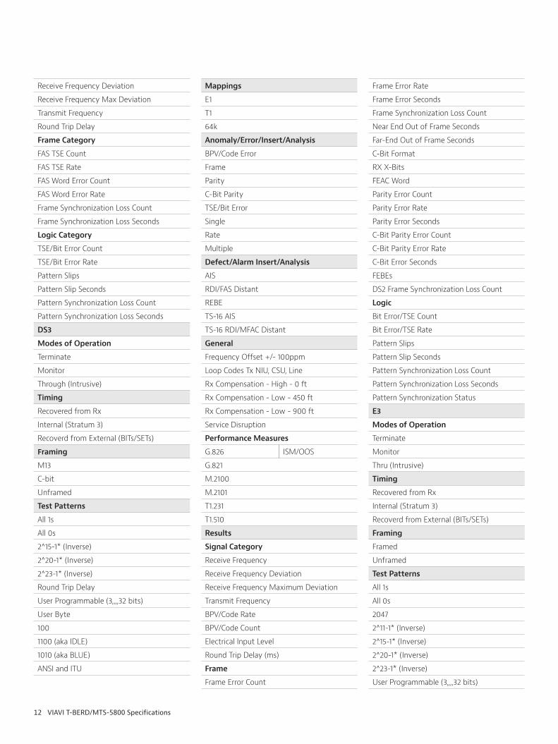
12 VIAVI T-BERD/MTS-5800 Specifications
Receive Frequency Deviation
Receive Frequency Max Deviation
Transmit Frequency
Round Trip Delay
Frame Category
FAS TSE Count
FAS TSE Rate
FAS Word Error Count
FAS Word Error Rate
Frame Synchronization Loss Count
Frame Synchronization Loss Seconds
Logic Category
TSE/Bit Error Count
TSE/Bit Error Rate
Pattern Slips
Pattern Slip Seconds
Pattern Synchronization Loss Count
Pattern Synchronization Loss Seconds
DS3
Modes of Operation
Terminate
Monitor
Through (Intrusive)
Timing
Recovered from Rx
Internal (Stratum 3)
Recoverd from External (BITs/SETs)
Framing
M13
C-bit
Unframed
Test Patterns
All 1s
All 0s
2^15-1* (Inverse)
2^20-1* (Inverse)
2^23-1* (Inverse)
Round Trip Delay
User Programmable (3,,,,32 bits)
User Byte
100
1100 (aka IDLE)
1010 (aka BLUE)
ANSI and ITU
Mappings
E1
T1
64k
Anomaly/Error/Insert/Analysis
BPV/Code Error
Frame
Parity
C-Bit Parity
TSE/Bit Error
Single
Rate
Multiple
Defect/Alarm Insert/Analysis
AIS
RDI/FAS Distant
REBE
TS-16 AIS
TS-16 RDI/MFAC Distant
General
Frequency Offset +/- 100ppm
Loop Codes Tx NIU, CSU, Line
Rx Compensation - High - 0 ft
Rx Compensation - Low - 450 ft
Rx Compensation - Low - 900 ft
Service Disruption
Performance Measures
G.826 ISM/OOS
G.821
M.2100
M.2101
T1.231
T1.510
Results
Signal Category
Receive Frequency
Receive Frequency Deviation
Receive Frequency Maximum Deviation
Transmit Frequency
BPV/Code Rate
BPV/Code Count
Electrical Input Level
Round Trip Delay (ms)
Frame
Frame Error Count
Frame Error Rate
Frame Error Seconds
Frame Synchronization Loss Count
Near End Out of Frame Seconds
Far-End Out of Frame Seconds
C-Bit Format
RX X-Bits
FEAC Word
Parity Error Count
Parity Error Rate
Parity Error Seconds
C-Bit Parity Error Count
C-Bit Parity Error Rate
C-Bit Error Seconds
FEBEs
DS2 Frame Synchronization Loss Count
Logic
Bit Error/TSE Count
Bit Error/TSE Rate
Pattern Slips
Pattern Slip Seconds
Pattern Synchronization Loss Count
Pattern Synchronization Loss Seconds
Pattern Synchronization Status
E3
Modes of Operation
Terminate
Monitor
Thru (Intrusive)
Timing
Recovered from Rx
Internal (Stratum 3)
Recoverd from External (BITs/SETs)
Framing
Framed
Unframed
Test Patterns
All 1s
All 0s
2047
2^11-1* (Inverse)
2^15-1* (Inverse)
2^20-1* (Inverse)
2^23-1* (Inverse)
User Programmable (3,,,,32 bits)

13 VIAVI T-BERD/MTS-5800 Specifications
User Byte
Round Trip Delay
1:1
1:3
1:4
1:7
ANSI and ITU
Mappings
E1
64k
Anomaly/Error Insert/Analysis
Code Error
FAS Error
TSE/Bit Error
Single
Rate
Defect/Alarm Insert/Analysis
AIS
RDI/FAS Distant
General
Frequency Offset Tx +/- 100ppm
Tx LBO - 0 dB Loss
Tx LBO - 6 dB Loss
National Bit Support - On/Off
Service Disruption
Performance Measures
G.826 ISM/OOS
G.821
M.2100
Results
Signal Category
Transmit Frequency
Receive Frequency
Receive Frequency Maximum Deviation
Electrical Input Level
Code Error Count
Code Error Rate
Round Trip Delay (ms)
APS Switch Time (ms)
Frame Category
FAS Bit Error Count
FAS Bit Error Rate
FAS Word Error Count
FAS Word Error Rate
Frame Synchronization Loss Count
8M FAS Word Error Rate
8M FAS Bit Error Count
8M FAS Bit Error Rate
8M FAS Word Error Count
8M FAS Word Error Rate
Logic Category
TSE/Bit Error Count
TSE/Bit Error Rate
Pattern Slips
Pattern Slip Seconds
Pattern Synchronization Loss Count
Pattern Synchronization Loss Seconds
Pattern Synchronization Status
E1
Modes of Operation
Terminate
Monitor
Thru (Intrusive)
Timing
Recovered from Rx
Internal (Stratum 3)
Recoverd from External (BITs/SETs)
Framing
Unframed
PCM30
PCM30C
PCM31
PCM31C
Test Patterns
All 1s
All 0s
2^15-1* (Inverse)
2^20-1* (Inverse)
2^23-1* (Inverse)
QRSS
User Programmable (32 bits)
Round Trip Delay
1:1
1:3
1:4
1:7
ANSI and ITU
Mappings
64k
Anomaly/Error Insert/Analysis
Code Error
FAS Error
MFAS Error
TSE/Bit Error
Single
Multiple
Rate
Defect/Alarm Insert/Analysis
AIS
REBE
TS-16 AIS
TS-16 RDI/MFAS Distant
General
Frequency Offset Tx +/- 100ppm
Service Disruption
Performance Measures
G.826 ISM/OOS
G.821
G.829 ISM/OOS
M.2100
Results
Signal Category
2M Receive Frequency
2M Reference Frequency
2M Receive Frequency Deviation
2M Receive Frequency Maximum Deviation
2M Transmit Frequency
Electrical Input Level
Code Error Count
Code Error Rate
Round Trip Delay (ms)
Timing Slips
Frame Slips
APS Switch Time
Logic Category
TSE/Bit Error Count
TSE/Bit Error Rate
Pattern Slips
Pattern Slip Seconds
Pattern Synchronization Loss Count
Pattern Synchronization Status
Alarm Category
FAS/Frame Synchronization
MFAS Synchronization
14 VIAVI T-BERD/MTS-5800 Specifications
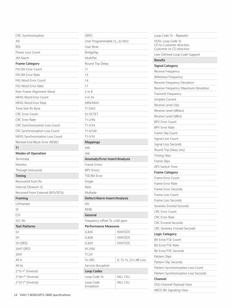
CRC Synchronization
AIS
RDI
Power Loss Count
2M Alarm
Frame Category
FAS Bit Error Count
FAS Bit Error Rate
FAS Word Error Count
FAS Word Error Rate
Non-Frame Alignment Word
MFAS Word Error Count
MFAS Word Error Rate
Time Slot Rx Byte
CRC Error Count
CRC Error Rate
CRC Synchronization Loss Count
FAS Synchronization Loss Count
MFAS Synchronization Loss Count
Remote End Block Error (REBE)
T1
Modes of Operation
Terminate
Monitor
Through (Intrusive)
Timing
Recovered from Rx
Internal (Stratum 3)
Recoverd from External (BITs/SETs)
Framing
Unframed
SF
ESF
SLC-96
Test Patterns
63
511
511 QRSS
2047 QRSS
2047
All 1s
All 0s
2^15-1* (Inverse)
2^20-1* (Inverse)
2^23-1* (Inverse)
QRSS
User Programmable (3,,,,32 bits)
User Byte
BridgeTap
MultiPat
Round Trip Delay
1:1
1:3
1:4
1:7
2 in 8
3 in 24
MIN/MAX
T1 DALY
55 OCTET
T1-2/96
T1-3/54
T1-4/120
T1-5/53
Mappings
64k
56k
Anomaly/Error Insert/Analysis
Frame Errors
BPV Errors
TSE/Bit Error
Single
Rate
Multiple
Defect/Alarm Insert/Analysis
AIS
REBE
General
Frequency offset Tx ±100 ppm
Performance Measures
G.826 ISM/OOS
G.828 ISM/OOS
G.829 ISM/OOS
M.2100
T1.231
Tx LBO 0, 7.5, 15, 22.5 dB Loss
Service disruption
Loop Codes
Loop Code Tx NIU, CSU
Loop Code Emulation
NIU, CSU
Loop Code Tx - Repeater
HDSL Loop Code TxCO to Customer directionCustomer to CO direction
User Defined Loop Code Support
Results
Signal Category
Receive Frequency
Reference Frequency
Receive Frequency Deviation
Receive Frequency Maximum Deviation
Transmit Frequency
Simplex Current
Receive Level (Vp)
Receive Level (dBdsx)
Receive Level (dBm)
BPV Error Count
BPV Error Rate
Frame Slip Count
Signal Loss Count
Signal Loss Seconds
Round Trip Delay (ms)
Timing Slips
Frame Slips
APS Switch Time
Frame Category
Frame Error Count
Frame Error Rate
Frame Error Seconds
Frame Loss Count
Frame Loss Seconds
Severely Errored Seconds
CRC Error Count
CRC Error Rate
CRC Errored Seconds
CRC Severely Errored Seconds
Logic Category
Bit Error/TSE Count
Bit Error/TSE Rate
Bit Error/TSE Seconds
Pattern Slips
Pattern Slip Seconds
Pattern Synchronization Loss Count
Pattern Synchronization Loss Seconds
Channel
DSO Channel Payload View
ABCD Bit Signaling View
15 VIAVI T-BERD/MTS-5800 Specifications
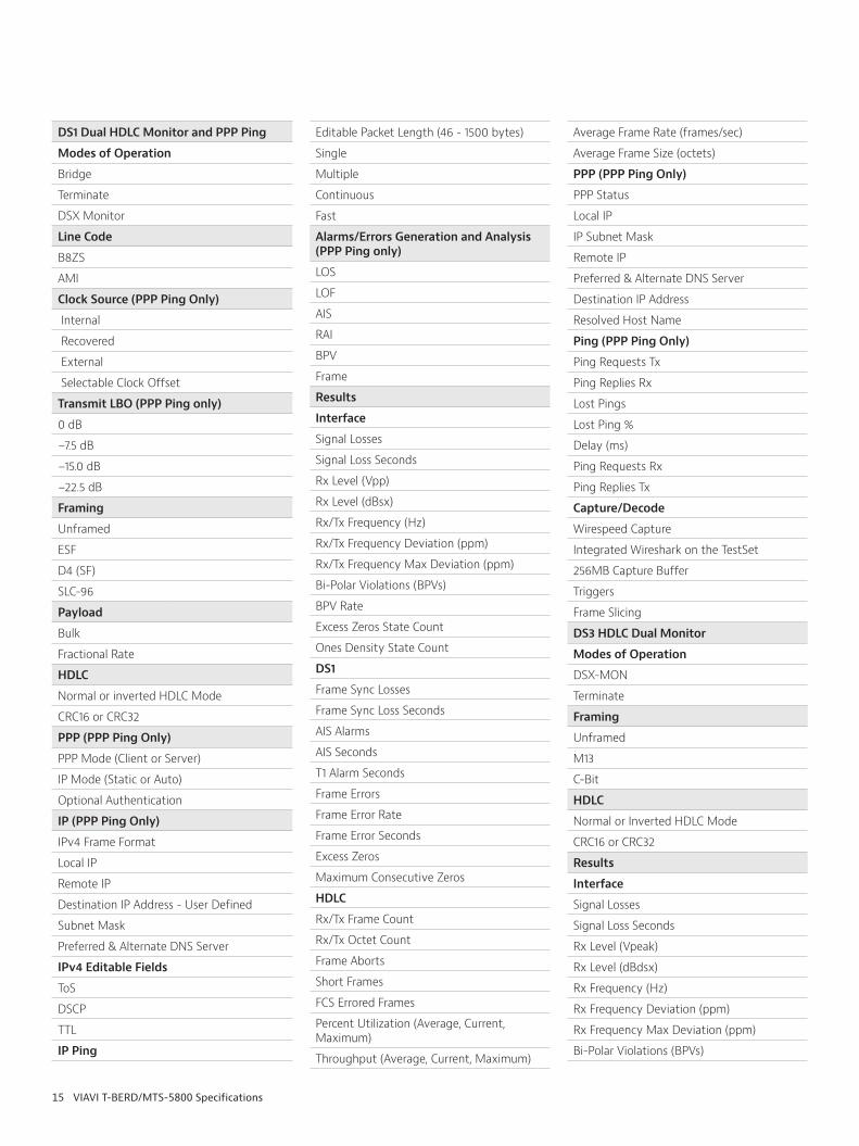
DS1 Dual HDLC Monitor and PPP Ping
Modes of Operation
Bridge
Terminate
DSX Monitor
Line Code
B8ZS
AMI
Clock Source (PPP Ping Only)
Internal
Recovered
External
Selectable Clock Offset
Transmit LBO (PPP Ping only)
0 dB
−7.5 dB
−15.0 dB
−22.5 dB
Framing
Unframed
ESF
D4 (SF)
SLC-96
Payload
Bulk
Fractional Rate
HDLC
Normal or inverted HDLC Mode
CRC16 or CRC32
PPP (PPP Ping Only)
PPP Mode (Client or Server)
IP Mode (Static or Auto)
Optional Authentication
IP (PPP Ping Only)
IPv4 Frame Format
Local IP
Remote IP
Destination IP Address - User Defined
Subnet Mask
Preferred & Alternate DNS Server
IPv4 Editable Fields
ToS
DSCP
TTL
IP Ping
Editable Packet Length (46 - 1500 bytes)
Single
Multiple
Continuous
Fast
Alarms/Errors Generation and Analysis (PPP Ping only)
LOS
LOF
AIS
RAI
BPV
Frame
Results
Interface
Signal Losses
Signal Loss Seconds
Rx Level (Vpp)
Rx Level (dBsx)
Rx/Tx Frequency (Hz)
Rx/Tx Frequency Deviation (ppm)
Rx/Tx Frequency Max Deviation (ppm)
Bi-Polar Violations (BPVs)
BPV Rate
Excess Zeros State Count
Ones Density State Count
DS1
Frame Sync Losses
Frame Sync Loss Seconds
AIS Alarms
AIS Seconds
T1 Alarm Seconds
Frame Errors
Frame Error Rate
Frame Error Seconds
Excess Zeros
Maximum Consecutive Zeros
HDLC
Rx/Tx Frame Count
Rx/Tx Octet Count
Frame Aborts
Short Frames
FCS Errored Frames
Percent Utilization (Average, Current, Maximum)
Throughput (Average, Current, Maximum)
Average Frame Rate (frames/sec)
Average Frame Size (octets)
PPP (PPP Ping Only)
PPP Status
Local IP
IP Subnet Mask
Remote IP
Preferred & Alternate DNS Server
Destination IP Address
Resolved Host Name
Ping (PPP Ping Only)
Ping Requests Tx
Ping Replies Rx
Lost Pings
Lost Ping %
Delay (ms)
Ping Requests Rx
Ping Replies Tx
Capture/Decode
Wirespeed Capture
Integrated Wireshark on the TestSet
256MB Capture Buffer
Triggers
Frame Slicing
DS3 HDLC Dual Monitor
Modes of Operation
DSX-MON
Terminate
Framing
Unframed
M13
C-Bit
HDLC
Normal or Inverted HDLC Mode
CRC16 or CRC32
Results
Interface
Signal Losses
Signal Loss Seconds
Rx Level (Vpeak)
Rx Level (dBdsx)
Rx Frequency (Hz)
Rx Frequency Deviation (ppm)
Rx Frequency Max Deviation (ppm)
Bi-Polar Violations (BPVs)

16 VIAVI T-BERD/MTS-5800 Specifications
BPV Rate
BPV Error Seconds
Excess Zeros Count
Excess Zeros Seconds
DS3
Frame Sync Losses
Frame Sync Loss Seconds
Near End OOF Seconds
Far End OOF Seconds
AIS Seconds
RAI Seconds
FEAC Word
Frame Errors
Frame Error Rate
Parity Errors
Parity Error Bit Rate
C-Bit Errors
C-Bit Error Rate
C-Bit Error Seconds
C-Bit Frame Mismatch Seconds
C-Bit Sync Loss Seconds
FEBEs
FEBE Rate
FEBE Seconds
Rx X-Bits
HDLC
Rx Frame Count
Rx Octet Count
Frame Aborts
Short Frames
FCS Errored Frames
Percent Utilization (Average, Current, Maximum)
Throughput (Average, Current, Maximum)
Average Frame Rate (frames/sec)
Average Frame Size (octets)
CPRI
Test Interfaces/Bit Rates
614 Mbps optical (Rate 1)
Dual Port Capable
1.2 Gbps optical (Rate 2)
Dual Port Capable
2.4 Gbps optical (Rate 3)
Dual Port Capable
3.1 Gbps optical (Rate 4)
Dual Port Capable
4.9 Gbps optical (Rate 5)
Dual Port Capable
6.1 Gbps optical (Rate 6)
Dual Port Capable
9.8 Gbps optical (Rate 7)
Dual Port Capable
10.137 Gbps optical (Rate 8)
Dual Port Capable
12.2 Gbps Optical (Rate 9)
Dual Port Capable
Laser Type
SFP
SFP+
SFP+ Tuneable
Modes of Operation
Terminate
Monitor/Thru
Timing
Recoverd from Rx (Slave)
Internal (Stratum 3) (Master)
Recoverd from External (BITs/SETs) (Master)
Recoverd from 10MHz clock (Master)
CPRI Automation
CPRI Service Activation automated workflow
CPRI Features
Optical/Electrical Power Level
Freq Offset Transmit/Receive
CPRI Startup Sequence - Normal or Bypass
Signal Generation and Monitoring
L1 - PRBS Pattern Inserted in Hyperframe Structure
L2 - PRBS Pattern Inserted in CPRI Basic Frame
L2 - PRBS Pattern Inserted in CPRI Antenna-carrier (AxC) Group
L2 Test Waveform Inserted in CPRI Antenna-carrier (AxC) Group
Interface Type
Master
Slave
Selectable CPRI Protocol Verion
Control and Management (C&M) Channel
Ethernet
HDLC
Selectable C&M Channel Rate
Service Disruption Measurements
SD Separation/Debounce Time Setting
SD Threshold Time Settings
Round-Trip Delay Measurement
RTD Measurement Accuracy
PRBS Patterns
2^15-1, 2^15-1 Inverse
2^20-1, 2^20-1 Inverse
2^23-1, 2^23-1 Inverse
2^31-1, 2^31-1 Inverse
Delay
Live
Digital Word
ANSI and ITU implementations
Anomaly/Errors Generation
Bit/TSE
Code
K30.7
Running Disparity
Insert - Single
Insert - Rate
CPRI AxC Mapping
Mapping Method: Method 1
Sample Width
Bandwidth
AxC Group Number
Offset
Test Waveform Selections
Continuous Wave (CW)
LTE-FDD TM1.1
LTE-FDD TM1.2
LTE-FDD TM2
LTE-FDD TM3.1
LTE-FDD TM3.2
LTE-FDD TM3.3
Loopback AxC (ALU/Nokia RRH)
Set Power levels and Bands (ALU/Nokia RRH)
Defects/Alarms Generation/Analysis
LOS
LOF
SDI
RAI
Results
Results Accuracy
1ns
Signal Category
Signal Losses

17 VIAVI T-BERD/MTS-5800 Specifications
Sync Loss Seconds
Optical Rx Overload
Optical Rx Level (dBm)
Receive Frequency
Receive Frequency Deviation
Receive Frequency Maximum Deviation
Transmit Frequency
Tx Frequency Deviation (Hz)
Tx Frequency Deviation (ppm)
Tx Frequency Max Deviation (ppm)
CPRI Inband Protocol
Tx/Rx Protocol Version
Tx/Rx C&M HDLC Rate
Tx/Rx C&M Ethernet Subchannel Number
Port Type (Master/Slave)
Start-up State
CPRI Counts
Code Word Count Tx/Rx
Frame Count Tx/Rx
Error Stats
Word Sync Loss Events
Word Sync Loss Seconds
Code Violations
Code Violation Rate
Code Violation Seconds
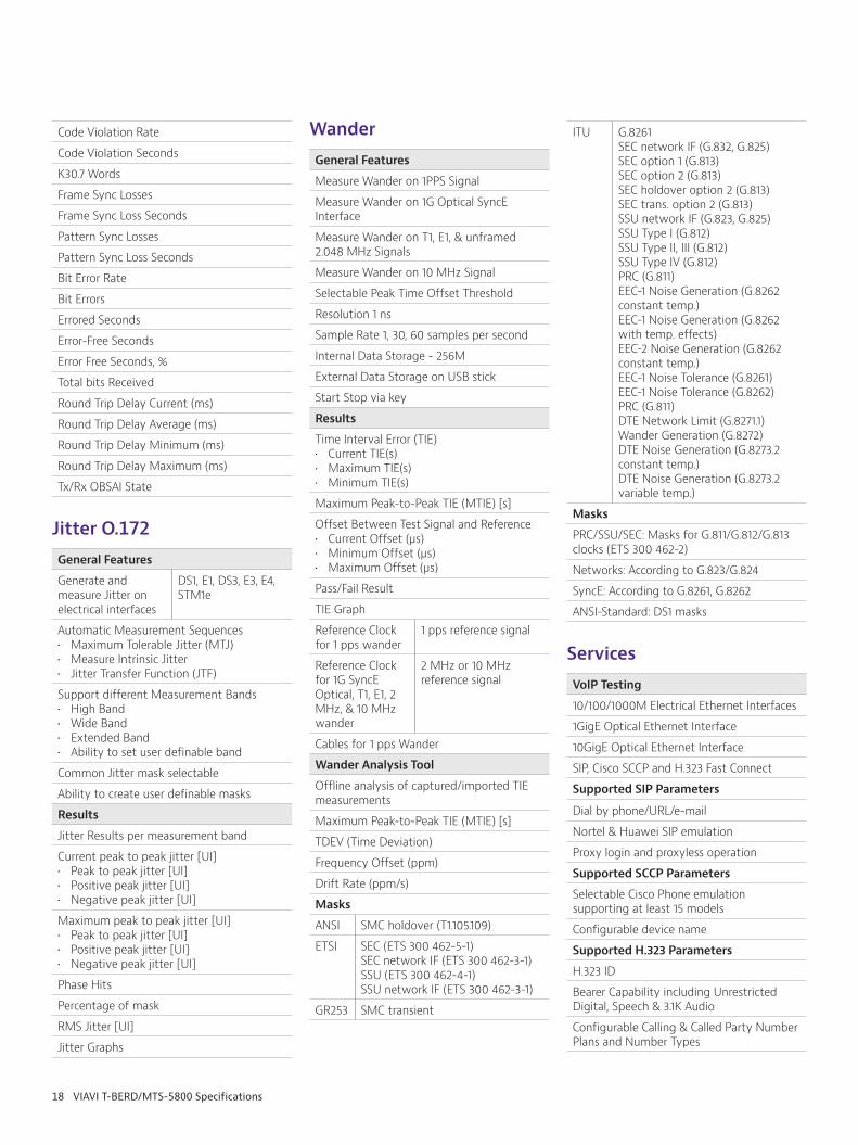
K30.7 Words
Frame Sync Loss Events
Frame Sync Loss Seconds
Pattern Sync Losses
Pattern Sync Loss Seconds
Bit Error Rate
Bit Errors
Errored Seconds
Error-Free Seconds
Error Free Seconds, %
Total bits Received
Round Trip Delay Current (ms)
Round Trip Delay Average (ms)
Round Trip Delay Minimum (ms)
Round Trip Delay Maximum (ms)
Remote LOS
Remote LOS Seconds
Remote LOF
Remote LOF Seconds
RAI
RAI Seconds
SDI
SDI Seconds
Running Disparity Errors
Running Disparity Error Rate
RRH Testing (available for ALU RRH)
RRH SW version
RRH serial number
RRH SFP information
RRH CPRI Reset
RRH Alarm Insertion
OBSAI
Test Interfaces/Bit Rates
768 Mbps Optical Dual Port Capable
1.5 Gbps Optical Dual Port Capable
3.1 Gbps Optical Dual Port Capable
6.1 Gbps Optical Dual Port Capable
Laser Type
SFP
SPF+
SFP+ Tunable
Modes of Operation
Terminate
Monitor/Thru
Timing
Recoverd from Rx (Slave)
Internal (Stratum 3) (Master)
Recoverd from External (BITs/SETs) (Master)
Recoverd from 10MHz clock (Master)
OBSAI Features
Optical/Electrical Power Level
Freq Offset Transmit/Receive
PRBS Generation and Monitoring
Unframed
L1 - Pattern Inserted in Frame Structure
L2 - Pattern Inserted in OBSAI Message
OBSAI Interface
Selectable Port Type (Master or Slave)
LOS Enable (On or Off)
Force Tx Idle (On or Off)
Definable RP3 Address
Selectable RP3 Type (WCDMA/FDD, GSM/EDGE, WiMAX 802.16, LTE)
Selectable Number of Message Groups in Master Frame
Selectable Number of Message Slots in Message Group
Selectable Number of Idle Bytes After Message Group
FCB Message Generation
Round Trip Delay Measurement
RTD Measurement Accuracy
PRBS Patterns
2^15-1, 2^15-1 Inverse
2^20-1, 2^20-1 Inverse
2^23-1, 2^23-1 Inverse
2^31-1, 2^31-1 Inverse
D6.6 D25.6
Delay
Live
Digital Word
Anomaly/Errors Generation
Bit
Code
Insert - Single
Insert - Rate
Results
Signal Category
Signal Losses
Sync Loss Seconds
Optical Rx Overload
Optical Rx Level (dBm)
Receive Frequency
Receive Frequency Deviation
Receive Frequency Maximum Deviation
Transmit Frequency
Tx Frequency Deviation (Hz)
Tx Frequency Deviation (ppm)
Tx Frequency Max Deviation (ppm)
OBSAI Counts
Code Word Count Tx/Rx
Frame Count Tx/Rx
Message Group Counts Tx/Rx
Receive Message Counts: Control, Measurement, WCDMA/FDD, WCDMA/TDD, GSM/EDGE, TETRA, CDMA2000, WLAN, Loopback, Frame Clock Burst, Ethernet, RTT, WiMAX, Virtual HW Reset, LTE, Generic Packet, Multi-hop RTT
Error Stats
Word Sync Loss Events
Word Sync Loss Seconds
Code Violations
18 VIAVI T-BERD/MTS-5800 Specifications
Code Violation Rate
Code Violation Seconds
K30.7 Words
Frame Sync Losses
Frame Sync Loss Seconds
Pattern Sync Losses
Pattern Sync Loss Seconds
Bit Error Rate
Bit Errors
Errored Seconds
Error-Free Seconds
Error Free Seconds, %
Total bits Received
Round Trip Delay Current (ms)
Round Trip Delay Average (ms)
Round Trip Delay Minimum (ms)
Round Trip Delay Maximum (ms)
Tx/Rx OBSAI State
Jitter O.172
General Features
Generate and measure Jitter on electrical interfaces
DS1, E1, DS3, E3, E4, STM1e
Automatic Measurement Sequences• Maximum Tolerable Jitter (MTJ)• Measure Intrinsic Jitter• Jitter Transfer Function (JTF)
Support different Measurement Bands• High Band• Wide Band• Extended Band• Ability to set user definable band
Common Jitter mask selectable
Ability to create user definable masks
Results
Jitter Results per measurement band
Current peak to peak jitter [UI]• Peak to peak jitter [UI]• Positive peak jitter [UI]• Negative peak jitter [UI]
Maximum peak to peak jitter [UI]• Peak to peak jitter [UI]• Positive peak jitter [UI]• Negative peak jitter [UI]
Phase Hits
Percentage of mask
RMS Jitter [UI]
Jitter Graphs
Wander
General Features
Measure Wander on 1PPS Signal
Measure Wander on 1G Optical SyncE Interface
Measure Wander on T1, E1, & unframed 2.048 MHz Signals
Measure Wander on 10 MHz Signal
Selectable Peak Time Offset Threshold
Resolution 1 ns
Sample Rate 1, 30, 60 samples per second
Internal Data Storage - 256M
External Data Storage on USB stick
Start Stop via key
Results
Time Interval Error (TIE)• Current TIE(s) • Maximum TIE(s) • Minimum TIE(s)
Maximum Peak-to-Peak TIE (MTIE) [s]
Offset Between Test Signal and Reference• Current Offset (μs) • Minimum Offset (μs) • Maximum Offset (μs)
Pass/Fail Result
TIE Graph
Reference Clock for 1 pps wander
1 pps reference signal
Reference Clock for 1G SyncE Optical, T1, E1, 2 MHz, & 10 MHz wander
2 MHz or 10 MHz reference signal
Cables for 1 pps Wander
Wander Analysis Tool
Offline analysis of captured/imported TIE measurements
Maximum Peak-to-Peak TIE (MTIE) [s]
TDEV (Time Deviation)
Frequency Offset (ppm)
Drift Rate (ppm/s)
Masks
ANSI SMC holdover (T1.105.109)
ETSI SEC (ETS 300 462-5-1)SEC network IF (ETS 300 462-3-1)SSU (ETS 300 462-4-1)SSU network IF (ETS 300 462-3-1)
GR253 SMC transient
ITU G.8261SEC network IF (G.832, G.825)SEC option 1 (G.813)SEC option 2 (G.813)SEC holdover option 2 (G.813)SEC trans. option 2 (G.813)SSU network IF (G.823, G.825)SSU Type I (G.812)SSU Type II, III (G.812)SSU Type IV (G.812)PRC (G.811)EEC-1 Noise Generation (G.8262 constant temp.)EEC-1 Noise Generation (G.8262 with temp. effects)EEC-2 Noise Generation (G.8262 constant temp.)EEC-1 Noise Tolerance (G.8261)EEC-1 Noise Tolerance (G.8262)PRC (G.811)DTE Network Limit (G.8271.1)Wander Generation (G.8272)DTE Noise Generation (G.8273.2 constant temp.)DTE Noise Generation (G.8273.2 variable temp.)
Masks
PRC/SSU/SEC: Masks for G.811/G.812/G.813 clocks (ETS 300 462-2)
Networks: According to G.823/G.824
SyncE: According to G.8261, G.8262
ANSI-Standard: DS1 masks
Services
VoIP Testing
10/100/1000M Electrical Ethernet Interfaces
1GigE Optical Ethernet Interface
10GigE Optical Ethernet Interface
SIP, Cisco SCCP and H.323 Fast Connect
Supported SIP Parameters
Dial by phone/URL/e-mail
Nortel & Huawei SIP emulation
Proxy login and proxyless operation
Supported SCCP Parameters
Selectable Cisco Phone emulation supporting at least 15 models
Configurable device name
Supported H.323 Parameters
H.323 ID
Bearer Capability including Unrestricted Digital, Speech & 3.1K Audio
Configurable Calling & Called Party Number Plans and Number Types
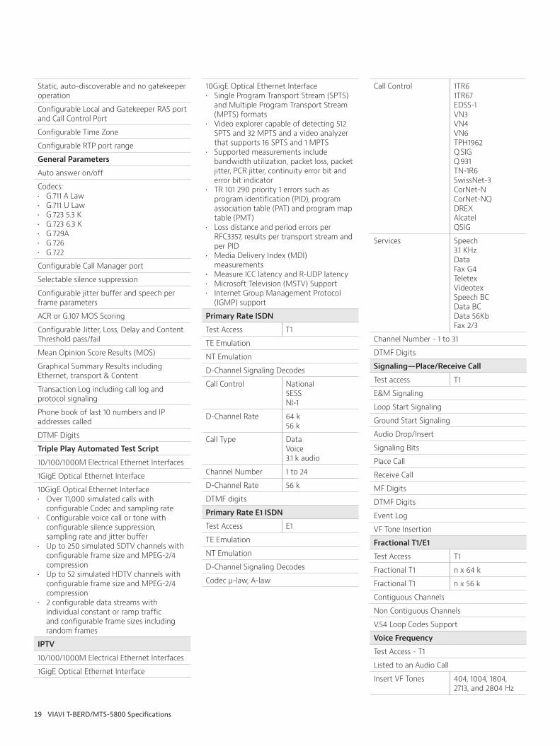
19 VIAVI T-BERD/MTS-5800 Specifications
Static, auto-discoverable and no gatekeeper operation
Configurable Local and Gatekeeper RAS port and Call Control Port
Configurable Time Zone
Configurable RTP port range
General Parameters
Auto answer on/off
Codecs: • G.711 A Law• G.711 U Law• G.723 5.3 K• G.723 6.3 K• G.729A• G.726• G.722
Configurable Call Manager port
Selectable silence suppression
Configurable jitter buffer and speech per frame parameters
ACR or G.107 MOS Scoring
Configurable Jitter, Loss, Delay and Content Threshold pass/fail
Mean Opinion Score Results (MOS)
Graphical Summary Results including Ethernet, transport & Content
Transaction Log including call log and protocol signaling
Phone book of last 10 numbers and IP addresses called
DTMF Digits
Triple Play Automated Test Script
10/100/1000M Electrical Ethernet Interfaces
1GigE Optical Ethernet Interface
10GigE Optical Ethernet Interface• Over 11,000 simulated calls with
configurable Codec and sampling rate• Configurable voice call or tone with
configurable silence suppression, sampling rate and jitter buffer
• Up to 250 simulated SDTV channels with configurable frame size and MPEG-2/4 compression
• Up to 52 simulated HDTV channels with configurable frame size and MPEG-2/4 compression
• 2 configurable data streams with individual constant or ramp traffic and configurable frame sizes including random frames
IPTV
10/100/1000M Electrical Ethernet Interfaces
1GigE Optical Ethernet Interface
10GigE Optical Ethernet Interface• Single Program Transport Stream (SPTS)
and Multiple Program Transport Stream (MPTS) formats
• Video explorer capable of detecting 512 SPTS and 32 MPTS and a video analyzer that supports 16 SPTS and 1 MPTS
• Supported measurements include bandwidth utilization, packet loss, packet jitter, PCR jitter, continuity error bit and error bit indicator
• TR 101 290 priority 1 errors such as program identification (PID), program association table (PAT) and program map table (PMT)
• Loss distance and period errors per RFC3357, results per transport stream and per PID
• Media Delivery Index (MDI) measurements
• Measure ICC latency and R-UDP latency• Microsoft Television (MSTV) Support• Internet Group Management Protocol
(IGMP) support
Primary Rate ISDN
Test Access T1
TE Emulation
NT Emulation
D-Channel Signaling Decodes
Call Control National5ESSNI-1
D-Channel Rate 64 k56 k
Call Type DataVoice3.1 k audio
Channel Number 1 to 24
D-Channel Rate 56 k
DTMF digits
Primary Rate E1 ISDN
Test Access E1
TE Emulation
NT Emulation
D-Channel Signaling Decodes
Codec μ-law, A-law
Call Control 1TR61TR67EDSS-1VN3VN4VN6TPH1962Q.SIGQ.931TN-1R6SwissNet-3CorNet-NCorNet-NQDREXAlcatel QSIG
Services Speech3.1 KHzDataFax G4TeletexVideotexSpeech BCData BCData 56KbFax 2/3
Channel Number - 1 to 31
DTMF Digits
Signaling—Place/Receive Call
Test access T1
E&M Signaling
Loop Start Signaling
Ground Start Signaling
Audio Drop/Insert
Signaling Bits
Place Call
Receive Call
MF Digits
DTMF Digits
Event Log
VF Tone Insertion
Fractional T1/E1
Test Access T1
Fractional T1 n x 64 k
Fractional T1 n x 56 k
Contiguous Channels
Non Contiguous Channels
V.54 Loop Codes Support
Voice Frequency
Test Access - T1
Listed to an Audio Call
Insert VF Tones 404, 1004, 1804, 2713, and 2804 Hz

20 VIAVI T-BERD/MTS-5800 Specifications
User Frequency
Quiet Tone
Holding Tone
Three Tone
Frequency Sweep
Impulse Noise
Rx Frequency
Level (dBm)
DC Offset mV
Fiber Inspection
Optical Fiber Microscope
The Test Equipment shall be able to accept an optical video microscope.
The connector image shall be displayed on the Test Equipment and saved into a .JPEG file format.
The microscope shall offer a switchable 200/400x magnification capability.
It shall be provided with the dedicated tips to inspect fiber connectors on the patch panel and the patch cords.
The microscope shall be capable of automatically centering the fiber image
The microscope shall be capable of performing on-board Pass/Fail analysis
The microscope shall be compatible with Android tablets/smartphones
OTDR
OTDR Solution for Troubleshooting from Central Offices
Wavelengths: 1310 & 1550nm
Connector type: UPC or APC (Note: Only one should be selected)
Adapter type: FC or SC (Note: Only one should be selected)
Dynamic Range: • at 1310nm: 35dB • at 1550nm: 33dB
Event Dead Zone: • at 1310nm/1550nm: 1.5m maximum
Attenuation Dead Zone:• at 1310nm/1550nm: 6m maximum
Pulse width: 5ns to 20msPulse width: 5ns to 20ms
Number of data points: up to 128,000
Light source:• On the OTDR port• Wavelength: same as the OTDR • Output power: -3.5 dBm typical
Test results shall be stored in SOR format (Telcordia GR-196-CORE) as well as in PDF format
The test result page shall display the graphical OTDR trace and event table
The test solution shall be able to convert automatically the OTDR trace into an icon-based map that makes OTDR results interpretation quick and easy
OTDR Solution for FTTA & DAS Singlemode & Multimode Network Testing
Wavelengths: 850, 1300, 1310, 1550 nm
Connector type: UPC or APC for 1310nm/1550nm (Note: Only one should be selected) and UPC for 850/1300nm
Adapter type: FC, SC, LC or ST (Note: One or several can be selected)
Dynamic Range: • at 850nm: 26 dB• at 1300nm: 24 dB• at 1310nm: 37 dB• at 1550nm: 35 dB
Event Dead Zone:• at 850nm/1300nm: 0.8m maximum• at 1310nm/1550nm: 0.9m maximum
Attenuation Dead Zone: • at 850nm/1300nm: 4m maximum• at 1310nm/1550nm: 4m maximum
Pulse width: • at 850nm/1300nm: 3ns to 1ms • at 1310nm/1550nm: 3ns to 20μs
Number of data points: up to 128,000
Light source:• On the OTDR port• Wavelength: same as the OTDR • Output power: -3.5 dBm typical
Power meter:• On the OTDR port• Calibrated wavelengths: 850, 1300, 1310,
1490, 1550, 1625, 1650 nm• Power level range (MM/SM): -3 to
-30dBm / -2 to -50 dBm
The test result page shall display the graphical OTDR trace and event table
The test solution shall be able to convert automatically the OTDR trace into an icon-based map that makes OTDR results interpretation quick and easy
The test solution shall be able to identify and label network elements
OTDR Solution for Cloud RAN & Access/Backhaul Network Testing
Wavelengths: 1310, 1550, 1625 nm (Note: 1625nm is optional)
Connector type: UPC or APC (Note: Only one should be selected)
Adapter type: FC, SC, LC or ST (Note: One or several can be selected)
Dynamic Range:• at 1310nm: 40 dB• at 1550nm: 38 dB• at 1625nm : 37 dB
Event Dead Zone:• at 1310/1550/1625nm: 0.9m maximum
Attenuation Dead Zone: • at 1310/1550/1625nm: 4m maximum
Pulse width: 3ns to 20msNumber of data points: up to 128,000
Light source:• On the OTDR port• Wavelength: same as the OTDR • Output power: -3.5 dBm typical
Power Meter:• On the OTDR port• Calibrated wavelengths: 1310, 1490, 1550,
1625, 1650 nm• Power level range: 0 to -50 dBm
The test result page shall display the graphical OTDR trace and event table
The test solution shall be able to convert automatically the OTDR trace into an icon-based map that makes OTDR results interpretation quick and easy
OTDR Solution for Metro & Access/Backhaul Network Testing
Wavelengths: 1310, 1550, 1625 nm (Note: 1625nm is optional)
Connector type: UPC or APC (Note: Only one should be selected)
Adapter type: FC, SC, LC or ST (Note: One or several can be selected)
Dynamic Range:• at 1310nm: 43 dB• at 1550nm: 43 dB• at 1625nm : 41dB
Event Dead Zone:• at 1310/1550/1625nm: 0.8m maximum
Attenuation Dead Zone:• at 1310/1550/1625nm: 4m maximum
Pulse width: 3ns to 20ms
Number of data points: up to 256,000
Light source:• On the OTDR port• Wavelength: same as the OTDR • Output power: -3.5 dBm typical

21 VIAVI T-BERD/MTS-5800 Specifications
Power Meter:• On the OTDR port• Calibrated wavelengths: 1310, 1490, 1550,
1625, 1650 nm• Power level range: 0 to -50 dBm
The test result page shall display the graphical OTDR trace and event table
The test solution shall be able to convert automatically the OTDR trace into an icon-based map that makes OTDR results interpretation quick and easy
OTDR Solution for CWDM Network Testing
8 CWDM wavelengths should be available on 1 optical port
Wavelengths:1471, 1491, 1511, 1531, 1551, 1571, 1591, 1611nm
Connector type: UPC or APC (Note: Only one should be selected)
Adapter type: FC, SC or LC (Note: One or several can be selected)
Dynamic Range: 35dB
Event Dead Zone:• at 1310/1550/1625nm: 1.5m maximum
Attenuation Dead Zone: • at 1310/1550/1625nm: 5m maximum
Pulse width: 10ns to 20ms
Number of data points: up to 256,000
Light source:• On the OTDR port• Wavelength: same as the OTDR • Output power: -3.5 dBm typical
The test result page shall display the graphical OTDR trace and event table
The test solution shall be able to convert automatically the OTDR trace into an icon-based map that makes OTDR results interpretation quick and easy
Optical Spectrum Analyzer
Optical Spectrum Analyzer Solution for Mobile Backhaul Service Activation
Connector type: PC
Adapter type: FC, SC, LC or ST (Note: One or several can be selected)
Spectral measurement
Wavelength range: From 1260 to 1625 nm
Wavelength accuracy: ±0.5 nm
Readout resolution: 0.001nm
Resolution bandwidth FWHM: 4nm
Minimum channel spacing: 8 nm
Power measurement
Dynamic range: –55 to +10 dBm
Noise floor RMS -55 dBm
Absolute accuracy: ±0.5 dB
Linearity: ±0.1 dB
Readout resolution: 0.01 dB
Scanning time (1260 to 165 nm): <4 sec
Maximum total safe power: +15 dBm
Optical return loss: > 35 dB
The Optical Spectrum Analyzer shall be equipped with a bay for up to 2 SFPs (optional)
Precision Timing Reference
Precision Timing Reference for Mobile Backhaul (PTP) Service Activation
Connector types: • SMA for GPS Antenna, • SMB for 1PPS and • 10 MHz Timing Inputs and Outputs
Integral GPS Receiver
Support for GNSS tuning including GPS, GLONASS, Beidou, and SBAS
Support for Cable/Antenna Calibration factor
GPS Synchronization Modes; Dynamic, Static, and Survey
Capable of savings surveyed locations and recalling saved locations
Capable of powering external antenna with 5 VDC or 3.3 VDC
Capable of detecting short circuit and open circuit fault conditions with external antenna
Capable of providing accurate timing with only a single satellite visible in static timing mode
Support for user tuning of minimum satellite elevation angle
Provides realtime satellite constellation sky plot identifying potential visible satellites and those being used
Provides realtime bar graph of satellite Carrier to Noise Ratio (CNR) for all visible satellites
Support for 72 channels; 32 for satellite tracking, 40 for acquisition aiding and noise estimation
Rubidium Clock
Support for two 1PPS inputs and capable of measuring phase difference between them down to 5nsec
Support for measuring ToD offset for a device under test with NMEA and G.8271 (draft) formats
Support for a 10MHz input
Support for a 1PPS output disciplined to the Rubidium clock
Support for a 10MHz output disciplined to the Rubidium clock
Selectable auto-power on for the Rubidium clock upon instrument power-up
Minimum holdover of 7 usec over 24 hours over full temperature range
Minimum oscillator stability of 1.5E-11 over 2 hours.
GPS Results
Number of satellites used
UTC Time
Estimated position error
Sky plot
Carrier to Noise bar graph
Carrier to Noise (C/No) measurement per satellite
Mean C/No measurement (current and average)
C/No Bar Chart
Mean 3D Accuracy
Position Dilution of Precision (current and average)
Leap seconds
Event Log
Rubidium Clock Results
Total holdover time elapsed
Holdover time remaining (for selectable clock accuracy)
Synchronization state (Course tune, Intermediate Tune, Fine Tune)
Event Log

© 2019 VIAVI Solutions Inc. Product specifications and descriptions in this document are subject to change without notice. 5800v2-ds-tfs-nse-ae 30175905 910 0519
C37.94
Test Interfaces/Bit Rates
2.048Mhz Dual Port Capable
Laser Type
SFP
Modes of Operation
Terminate
Framing
Framed
Payload
N x 64 kbps
Test Patterns
2^11 -1 (INV)
2^15 -1 (INV)
2^20 -1 (INV)
2^23 -1 (INV)
QRSS
All Ones
All Zeros
Delay
Live
ANSI and ITU
Performance
G.826
G.821
M.2100
Alarms
LOF
RDI
Errors
FAS
Results
Interface
Signal Losses
Signal Loss Seconds
Optical Rx Overload
Optical Rx Level (dBm)
Optical Tx Level (dBm)
Laser Bias Current (mA)
Rx Frequency (Hz)
Rx Frequency Deviation (ppm)
Rx Frequency Maximum Deviation (ppm)
Tx Clock Source
Tx Frequency (Hz)
Tx frequency Deviation (ppm)
Tx Frequency Maximum Deviation (ppm)
C37.94 - Frame
Frame Sync Losses
Frame Sync Loss Seconds
LOFs
LOF Seconds
RDI Alarms
RDI Seconds
FAS Word Errors
FAS Word Error Rate
FAS Bit Errors
FAS Bit Error Rate
N x 64 kbps
Payload - BERT
Pattern Sync Losses
Pattern Sync Loss Seconds
Round Trip Delay (ms)
Round Trip Delay Avg (ms)
Round Trip Delay Minimum (ms)
Round Trip Delay Maximum (ms)
99 Washington Street Melrose, MA 02176 Phone 781-665-1400Toll Free 1-800-517-8431
Visit us at www.TestEquipmentDepot.com