
9.9 SAND FILTERS
18
New Jersey Stormwater Best Management Practices Manual Updated September 2014 Chapter 9.9 Sand Filters Page 1 9.9 SAND FILTERS A sand filter is a stormwater management system designed to maximize the removal of pollutants from stormwater. It consists of a pre-treatment zone and a treatment zone, which includes the sand bed, and in underdrained systems, and the underlying components. Pollutants are treated through settling, filtration, and adsorption by the sand bed. The total suspended solids (TSS) removal rate is 80%. N.J.A.C. 7:8 Stormwater Management Rules - Design and Performance Standards Nonstructural Strategy Not Allowed Water Quantity Yes, when designed as an on-line system Groundwater Recharge Yes, for systems designed to infiltrate into the subsoil Water Quality 80% TSS Water Quality Mechanisms and Corresponding Criteria Settling Storage Volume Entire Water Quality Design Storm Volume Filtration Sand bed minimum thickness 18 inches Maximum storage above sand bed 24 inches Maximum design permeability rate of sand bed 2 inches/hour Minimum top soil permeability rate, if using optional vegetative cover Underdrained Systems: 2x the hydraulic head loss of the underdrain, or Systems Designed to Infiltrate: 2x the permeability of the subsoil
Transcript of 9.9 SAND FILTERS
New Jersey Stormwater Best Management Practices Manual Updated September 2014 Chapter 9.9 Sand Filters Page 1
9.9 SAND FILTERS
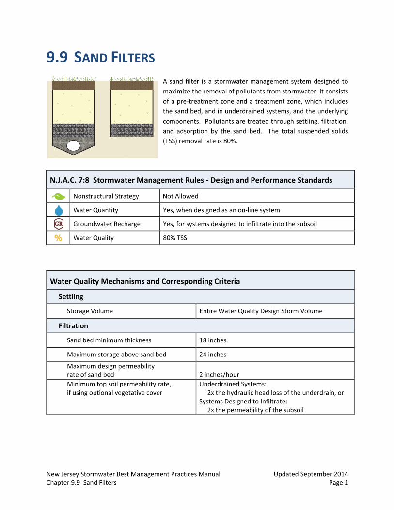
A sand filter is a stormwater management system designed to
maximize the removal of pollutants from stormwater. It consists
of a pre-treatment zone and a treatment zone, which includes
the sand bed, and in underdrained systems, and the underlying
components. Pollutants are treated through settling, filtration,
and adsorption by the sand bed. The total suspended solids
(TSS) removal rate is 80%.
N.J.A.C. 7:8 Stormwater Management Rules - Design and Performance Standards
Nonstructural Strategy Not Allowed
Water Quantity Yes, when designed as an on-line system
Groundwater Recharge Yes, for systems designed to infiltrate into the subsoil
Water Quality 80% TSS
Water Quality Mechanisms and Corresponding Criteria
Settling
Storage Volume Entire Water Quality Design Storm Volume
Filtration
Sand bed minimum thickness 18 inches
Maximum storage above sand bed 24 inches
Maximum design permeability rate of sand bed
2 inches/hour
Minimum top soil permeability rate, if using optional vegetative cover
Underdrained Systems: 2x the hydraulic head loss of the underdrain, or Systems Designed to Infiltrate: 2x the permeability of the subsoil
New Jersey Stormwater Best Management Practices Manual Updated September 2014 Chapter 9.9 Sand Filters Page 2
Introduction
A sand filter is a stormwater management facility that uses sand to filter particles and particle-bound constituents from runoff. There are two types of sand filter systems: infiltration sand filters and underdrained sand filters; pollutant removal occurs solely in sand bed in both types of systems. Stormwater entering the sand filter is first conveyed through the pretreatment zone where trash, debris and coarse sediment are removed. It then passes through the treatment zone and out of the system through either an outlet pipe, in an underdrained system, or through the subsoil via infiltration. Pollutants in runoff are treated in sand filters through the processes of settling, filtration and adsorption.
Due to the potential for groundwater contamination, the use of sand filters designed to infiltrate into the subsoil, and all stormwater infiltration best management practices (BMP), is prohibited in areas where high pollutant or sediment loading is anticipated. For more information regarding areas where stormwater runoff infiltration is prohibited, refer to N.J.A.C. 7:8-5.4(a)2ii.
Sand filters are better suited for impervious drainage areas with high TSS, heavy metals and hydrocarbon loadings like roads, driveways, drive-up lanes, parking lots and urban areas. They are not recommended for use in pervious drainage areas where high sediment loads and organic material can clog the sand bed; where such loadings cannot be avoided, pretreatment is recommended.
Sand filters must have a maintenance plan and should be protected by easement, deed restriction, ordinance or other legal measures that prevent its neglect, adverse alteration or removal.
Applications
Sand filters may be designed to convey storm events larger than the Water Quality Design Storm; however, regardless of the design storm chosen, all sand filters must be designed for stability and capacity in accordance with the Standards for Soil Erosion and Sediment Control in New Jersey, as required by N.J.A.C. 7:8 Stormwater Management rules.
Sand filter systems designed to infiltrate into the subsoil may be used to meet the groundwater recharge requirements. For more information on computing ground water recharge, see Chapter 6: Groundwater Recharge.
To receive credit for a TSS removal rate of 80%, sand filters must be designed to treat the Water Quality Design Storm and in accordance with all of the following criteria.
New Jersey Stormwater Best Management Practices Manual Updated September 2014 Chapter 9.9 Sand Filters Page 3
Design Criteria
Basic Requirements
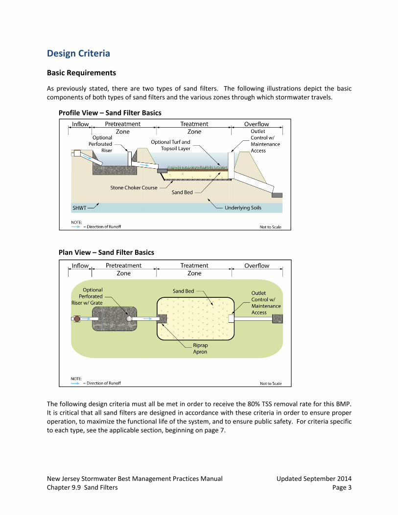
As previously stated, there are two types of sand filters. The following illustrations depict the basic components of both types of sand filters and the various zones through which stormwater travels.
Profile View – Sand Filter Basics
Plan View – Sand Filter Basics
The following design criteria must all be met in order to receive the 80% TSS removal rate for this BMP. It is critical that all sand filters are designed in accordance with these criteria in order to ensure proper operation, to maximize the functional life of the system, and to ensure public safety. For criteria specific to each type, see the applicable section, beginning on page 7.
New Jersey Stormwater Best Management Practices Manual Updated September 2014 Chapter 9.9 Sand Filters Page 4
Pretreatment
As with all other best management practices, pretreatment can extend the functional life and increase the pollutant removal capability of a sand filter by reducing incoming velocities and capturing coarser sediments.
Pretreatment may consist of a forebay or any of the structural BMPs found in Chapter 9: Structural Stormwater Management Measures.
There is no adopted TSS removal rate associated with forebays; therefore, their inclusion in any design should be solely for the purpose of facilitating maintenance. Forebays can be earthen, constructed of riprap, or made of concrete, and must comply with the following requirements:
□ The forebay must be designed to prevent scour of the receiving basin by outflow from the forebay.
□ The forebay should provide a minimum storage volume of 10% of the Water Quality Design Storm and be sized to hold the sediment volume expected between clean-outs.
□ It should fully drain within nine hours in order to facilitate maintenance and to prevent mosquito issues. Under no circumstances should there be any standing water in the forebay 72 hours after a precipitation event.
□ Surface forebays must meet or exceed the sizing for preformed scour holes in the Standard for Conduit Outlet Protection in the Standards for Soil Erosion and Sediment Control in New Jersey for a surface forebay.
□ The recommended Minimum surface area (sf) = 59 X Inflow (cfs).
If a concrete forebay is utilized, it must have at least two weep holes to facilitate low level drainage.
When using a structural BMP for pretreatment, it must be designed in accordance with the design requirements outlined in the respective chapter. For additional information on the design requirements of each structural BMP, refer to the appropriate chapter in this manual.
Inflow Drainage Area Limitations
The upstream inflow drainage area must be completely stabilized prior to sand filter use.
Storage Volume
The system must have sufficient storage volume to contain the Water Quality Design Storm runoff volume without overflow.
Sand filters are generally constructed as off-line systems. In off-line sand filters, most or all of the runoff from storms larger than the Water Quality Design Storm bypass the filter through an upstream diversion; this reduces the size of the required filter overflow, the filter’s long-term pollutant loading, associated maintenance, and the threat of erosion and scour caused by larger storm inflows. Sand filters, however, may also be constructed as on-line systems. On-line sand filters receive upstream runoff from all storms events; they provide treatment for the Water Quality Design Storm, and they convey the runoff from larger storms through an overflow. These on-line systems store and attenuate the larger storm events and provide runoff quantity

New Jersey Stormwater Best Management Practices Manual Updated September 2014 Chapter 9.9 Sand Filters Page 5
control; in such systems, the invert of the lowest quantity control outlet is set at or above the maximum water surface of the Water Quality Design Storm.
Placement of Riprap
The use of riprap in these systems should be limited to the area directly under the inflow to prevent scouring of the receiving sand.
Sand Bed
The thickness and character of the bed must provide adequate pollutant removal.
Minimum thickness: 18 inches.
Maximum storage above the sand bed: 24 inches.
The sand must meet the specifications for clean, medium-aggregate concrete sand in accordance with AASHTO M-6 or ASTM C-33, as certified by a professional engineer licensed in the State of New Jersey.
The maximum design permeability rate of sand bed is 2 inches/hour and must be verified prior to installation.
When using the 2 inches/hour permeability rate, a design drain time of 36 hours must be used.
Stone Choker Course
This layer must be between 1 and 2 inches.
The stone in this layer must meet the specifications for clean, coarse aggregate in accordance with AASHTO No. 57.
Permeability
The following specifications apply to the permeability rates of the sand bed, the stone choker course, the subsoil and the topsoil in systems designed with the optional vegetative cover.
The testing of all permeability rates must be consistent with Appendix E: Soil Testing Criteria in this manual.
Since the actual permeability rate may vary from soil testing results and may decrease over time, a factor of safety of 2 must be applied to the tested permeability rate to determine the design permeability rate. For example, if the tested permeability rate is 4 inches/hour, then the design rate would be 2 inches/hour. The design rate would then be used to compute the system’s Water Quality Design Storm drain time.
Post-construction testing of the system must be performed on the as-built sand filter in accordance with the Construction and Post-Construction Oversight and Soil Permeability Testing section in Appendix E: Soil Testing Criteria of this manual.
New Jersey Stormwater Best Management Practices Manual Updated September 2014 Chapter 9.9 Sand Filters Page 6
Outlet Structure
For systems designed with an outlet structure, trash racks must be installed at the intake to the outlet structure. They must also be designed to avoid acting as the hydraulic control for the system, and they must meet the following criteria, as required by N.J.A.C. 7:8-5.7(a)2 and 6.2(a):
□ Parallel bars spaced at 1-inch intervals, up to the elevation of the Water Quality Design Storm,
□ Minimum bar spacing: 1 inch, for elevations in excess of the Water Quality Design Storm,
□ Maximum bar spacing: 1/3 the diameter of the orifice or 1/3 the width of weir, with a maximum spacing of 6 inches, for elevations in excess of the Water Quality Design Storm,
□ Maximum average velocity of flow through clean rack: 2.5 feet/second, under full range of stage and discharge, computed on the basis of the net area of opening through rack,
□ Constructed of rigid, durable and corrosion-resistant material, and □ Designed to withstand a perpendicular live loading of 300 lbs./sf.
All sand filters must be designed to safely convey overflows to downstream drainage systems. The design of the overflow structure must be sufficient to provide safe, stable discharge of stormwater in the event of an overflow. Safe and stable discharge minimizes the possibility of erosion and flooding in down-gradient areas. Therefore, discharge in the event of an overflow must be consistent with the current version of Standards for Off-Site Stability found in the Standards for Soil Erosion and Sediment Control in New Jersey, as required by N.J.A.C. 7:8. Sand filters that are classified as dams under the NJDEP Dam Safety Standards at N.J.A.C. 7:20 must meet the overflow requirements under these regulations. Overflow capacity can be provided by a hydraulic structure, such as a weir or orifice, or a surface feature, such as a swale or open channel as site conditions allow.
The hydraulic design of the underdrain and overflow systems, as well as any stormwater quantity control outlet, must consider any significant tailwater effects of downstream waterways or facilities. This includes instances where the lowest invert in the outlet or overflow structure is below the flood hazard area design flood or tide elevation in a downstream waterway or storm sewer system.
Drain Time
The Water Quality Design Storm volume must fully drain through the sand filter system within 72 hours, based on the design permeability rate. Storage in excess of this time can render the system ineffective and may result in anaerobic conditions, odor, and both water quality and mosquito breeding issues.
When designing an underdrained sand filter, a design drain time of 36 hours and a sand bed permeability rate of 2 inches/hour must be used. However, when sizing an infiltration sand filter, both the permeability of the subsoil and the permeability of the sand bed must be taken into account, and the more restrictive permeability rate of the two layers must be used in sizing calculations.
New Jersey Stormwater Best Management Practices Manual Updated September 2014 Chapter 9.9 Sand Filters Page 7
Construction Specifications
The use of the sand filter system for sediment control during construction is discouraged; however, when unavoidable, excavation for the sediment basin should be at least 2 feet above the final design elevation of the basin bottom.
Basin excavation and sand placement should be performed with equipment placed outside of the basin bottom whenever possible. However, in circumstances where this is unavoidable, light earth moving equipment with oversized tires or tracks should be utilized.
The excavation for the sand filter bottom should only occur after all construction within its drainage area is completed and the drainage area is stabilized. If construction of the sand filter cannot be delayed, berms should be placed around the perimeter of the sand filter during all phases of construction, diverting all flows away from the filter. The berms should not be removed until all construction within the drainage area is completed and the area is stabilized.
Once the excavation is completed, the floor of the sand filter must be deeply tilled with a rotary tiller or disc harrow and smoothed over with a leveling drag, or equivalent grading equipment.
Once both the sand filter and its drainage area are stabilized, the infiltration rate of the sand bed must be retested to ensure that the design permeability rate is the same as the as-built permeability rate.

New Jersey Stormwater Best Management Practices Manual Updated September 2014 Chapter 9.9 Sand Filters Page 8
Types of Sand Filters
There are two types of sand filters:
1. Sand Filters with Underdrains 2. Sand Filters Designed to Infiltrate into the Subsoils
Individual Types of Sand Filters
The following section provides detailed design criteria for each type of sand filter; the illustrations feature a forebay in the pretreatment zone. The illustrations depict possible configurations and flow paths and are not intended to limit the design. An additional illustration providing a side by side comparison of the two types of sand filters is found on page 12.
Sand Filters with Underdrains
If vegetation is used above the sand bed, the permeability of the top soil must be at least two times the hydraulic head loss of the underdrain.
To ensure proper system operation, the gravel layer and the perforated underdrain piping must have infiltration and conveyance rates at least twice as fast as the design flow from the sand bed.
Filter fabric is required along the sides and the bottom of the system to prevent the migration of fines from the surrounding soil.
The underdrain piping must connect to a downstream location that is easily accessible for inspection and maintenance.
The drain time is determined by the hydraulic capacity of the underdrain, the permeability of the sand bed and the permeability of any additional material above it.
The seasonal high water table (SHWT) must be at least 1 foot below the bottom of the sand filter, including all piping and gravel material.
New Jersey Stormwater Best Management Practices Manual Updated September 2014 Chapter 9.9 Sand Filters Page 9
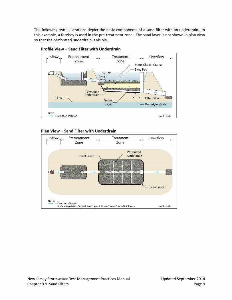
The following two illustrations depict the basic components of a sand filter with an underdrain. In this example, a forebay is used in the pre-treatment zone. The sand layer is not shown in plan view so that the perforated underdrain is visible.
Profile View – Sand Filter with Underdrain
Plan View – Sand Filter with Underdrain

New Jersey Stormwater Best Management Practices Manual Updated September 2014 Chapter 9.9 Sand Filters Page 10
Sand Filters Designed to Infiltrate into the Subsoil
The SHWT must be at least 2 feet below the bottom of the sand bed.
As with underdrained sand filter systems, filter fabric is required along the sides of the sand bed to prevent the migration of fines from the surrounding soil into the sand bed. However, unlike underdrained systems, filter fabric may not be used between the sand bed and the stone choker course because it may cause a layer of fines to collect resulting in a loss of permeability.
The drain time is determined by the permeability of the sand bed, the permeability of any additional materials above it, and the permeability of the subsoil.
The permeability rate of the top soil, if using the optional vegetated surface, must be twice the design permeability rate of the subsoil.
As with any infiltration BMP, groundwater mounding impacts must be assessed, as required by N.J.A.C. 7:8-5.4(a)2.iv.
Once construction is complete, the permeability rate of the subsoil below the basin must be retested to ensure that the subsoil was not compacted during construction.
New Jersey Stormwater Best Management Practices Manual Updated September 2014 Chapter 9.9 Sand Filters Page 11
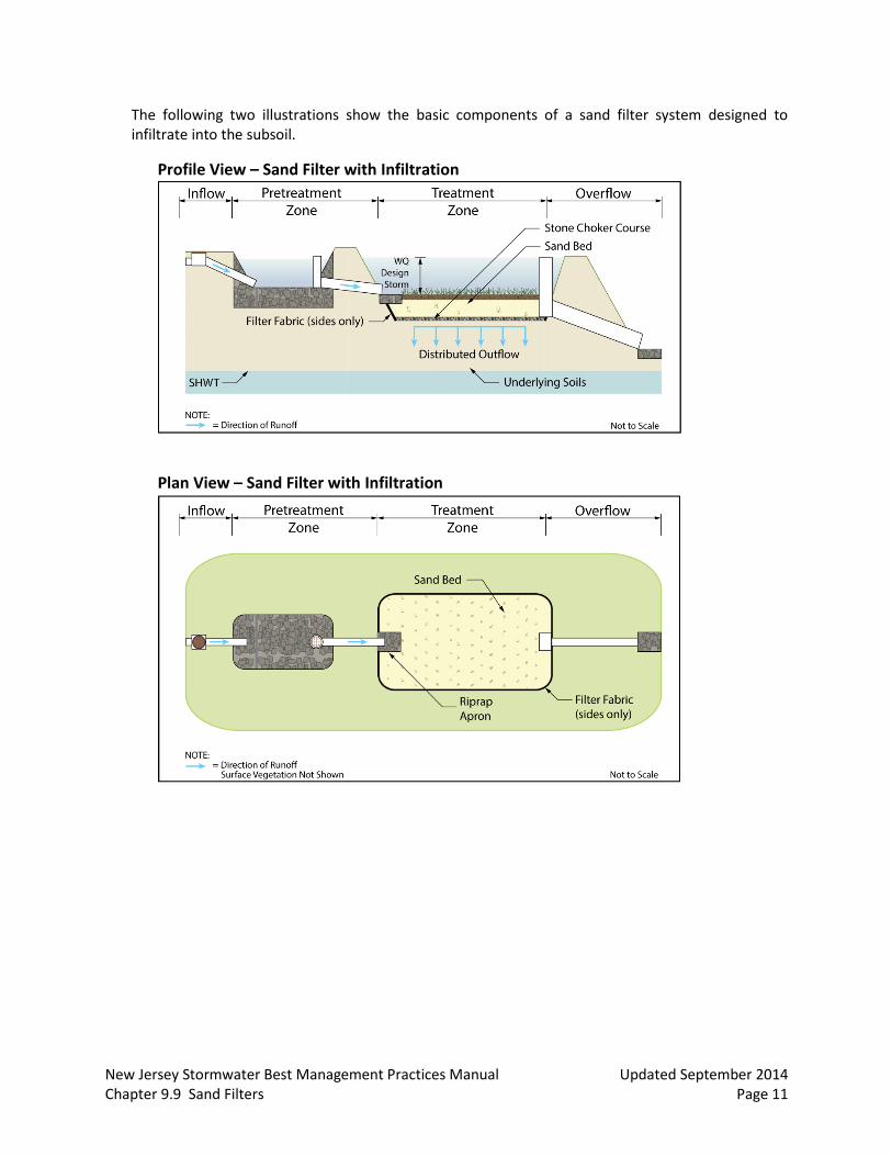
The following two illustrations show the basic components of a sand filter system designed to infiltrate into the subsoil.
Profile View – Sand Filter with Infiltration
Plan View – Sand Filter with Infiltration
New Jersey Stormwater Best Management Practices Manual Updated September 2014 Chapter 9.9 Sand Filters Page 12
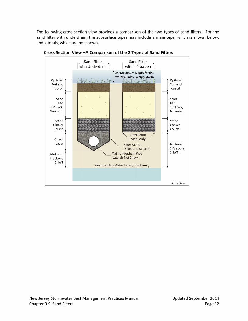
The following cross-section view provides a comparison of the two types of sand filters. For the sand filter with underdrain, the subsurface pipes may include a main pipe, which is shown below, and laterals, which are not shown.
Cross Section View –A Comparison of the 2 Types of Sand Filters
New Jersey Stormwater Best Management Practices Manual Updated September 2014 Chapter 9.9 Sand Filters Page 13
Designing A Sand Filter
The example below illustrates how to design a sand filter to treat the runoff generated by the Water Quality Design Storm. The following parameters apply:
Area = 1 acre CN Value = 98 (100% Impervious) Calculated Water Quality Design Storm Peak Flow Rate = 1.16 cfs Calculated Time to Peak = 1.54 hours Calculated Water Quality Design Storm Runoff Volume = 3,755 cf Forebay Primary Outflow: Perforated Riser Pipe Forebay Secondary Outflow: Broad-crested Weir Sand Bed Permeability Rate = 2 inches/hour Subsoil Permeability Rate = 8 inches/hour Forebay Surface Elevation = 1.10 ft Sand Bed Surface Elevation = 0.00 ft Assumed Depth of Water Quality Design Storm Runoff = 1 ft above the sand filter surface
Step #1: Forebay Sizing
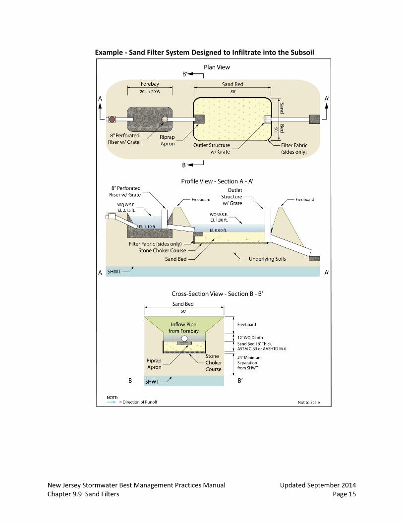
The forebay must be sized to hold 10% of the Water Quality Design Storm volume. Assuming the depth of water in the forebay is equal to the depth of the Water Quality Design Storm in the surface of the sand filter system, which is assumed to be 1 foot, a rectangular forebay with a width of 20 feet and a length of 20 feet will provide adequate storage volume. However, in order to facilitate drainage, the water surface elevation in the forebay must be greater than the water surface elevation in the sand filter; in addition, the perforations in the riser pipe must be designed to ensure that the forebay will drain within 9 hours.
In this example, the Water Quality Design Storm water surface elevation (WQ W.S.E.) in the forebay is 2.15 ft; this translates to a depth of 1.05 ft, with the additional 0.05 ft of depth resulting from head loss in the riser pipe. Based on the above elevations, the top of the riser pipe is set at an elevation of 2.20 ft. A grate or trash rack should be installed on the top of the riser to keep floatables from entering the riser pipe during large storm events.

New Jersey Stormwater Best Management Practices Manual Updated September 2014 Chapter 9.9 Sand Filters Page 14
Step #2: Sand Filter Sizing
When designing an infiltration sand filter, the permeability of the subsoil can affect the design permeability of the entire system; as previously stated, the maximum design permeability of any sand filter system is 10 inches/hour, and the maximum permeability of the sand bed, for the purposes of calculations, is 2 inches/hour. In this example, the sand filter does not utilize the optional surface vegetation. The minimum surface area of the sand bed is calculated by dividing the volume of runoff generated by the Water Quality Design Storm by both the maximum allowable drain time and the maximum allowed sand bed permeability rate.
A small surface area will result in a greater depth of storage for runoff.
The calculated depth is six times greater than the assumed depth of the Water Quality Design Storm runoff given at the beginning of the example. Rearranging the equation above to solve for the area yields:
The resulting surface area could be achieved with an 80 ft by 50 ft sand bed; however, the significantly larger surface area will reduce the drain time of the system to well below 36 hours.
Illustrations for this example are shown below.
New Jersey Stormwater Best Management Practices Manual Updated September 2014 Chapter 9.9 Sand Filters Page 15
Example - Sand Filter System Designed to Infiltrate into the Subsoil
New Jersey Stormwater Best Management Practices Manual Updated September 2014 Chapter 9.9 Sand Filters Page 16
Considerations
The following should be considered when utilizing a sand filter to treat stormwater runoff.
Optional Vegetative Cover
Vegetation may only be turf grass.
The permeability rate of the top soil, if using the optional vegetated surface, must be twice the design permeability rate of the subsoil.
Maintenance
Regular and effective maintenance is crucial to ensure effective sand filter performance; in addition, maintenance plans are required for all stormwater management facilities associated with a major development. There are a number of required elements in all maintenance plans, pursuant to N.J.A.C. 7:8-5.8; these are discussed in more detail in Chapter 8: Maintenance of Stormwater Management Measures. Furthermore, maintenance activities are required through various regulations, including the New Jersey Pollutant Discharge Elimination System (NJPDES) Rules, N.J.A.C. 7:14A. Specific maintenance requirements for sand filter systems are presented below; these requirements must be included in the sand filter’s maintenance plan.
General Maintenance
All structural components must be inspected, at least once annually, for cracking, subsidence, spalling, erosion and deterioration.
Components expected to receive and/or trap debris and sediment must be inspected for clogging at least twice annually.
Sediment removal should take place when all runoff has drained from the sand bed and the sand bed is dry.
Disposal of debris, trash, sediment and other waste material must be done at suitable disposal/recycling sites and in compliance with all applicable local, state and federal waste regulations.
Vegetated Areas
In sand filter systems with vegetated surfaces, bi-weekly inspections are required when establishing/restoring vegetation.
A minimum of one inspection during the growing season and one inspection during the non-growing season is required to ensure the health, density and diversity of the vegetation.
Mowing/trimming of vegetation must be performed on a regular schedule based on specific site conditions; perimeter grass should be mowed at least once a month during growing season.
New Jersey Stormwater Best Management Practices Manual Updated September 2014 Chapter 9.9 Sand Filters Page 17
Vegetative cover must be maintained at 85%; damage in excess of 50% must be addressed through replanting in accordance with the original specifications.
Vegetated areas must be inspected at least once annually for erosion, scour and unwanted growth; any unwanted growth should be removed with minimum disruption to the remaining vegetation.
All use of fertilizers, pesticides, mechanical treatments and other means to ensure optimum vegetation health must not compromise the intended purpose of the sand filter.
Drain Time
The sand bed must be inspected at least twice annually to determine if the permeability of the bed has decreased.
The approximate drain time for the maximum design storm runoff volume below the top of the sand bed must be indicated in the maintenance manual.
If the actual drain time is significantly different from the design drain time, the components that could provide hydraulic control must be evaluated and appropriate measures taken to return the sand filter to minimum and maximum drain time requirements.
If the sand filter fails to drain the Water Quality Design Storm within 72 hours, corrective action must be taken, up to and including the replacement of the upper layers of the sand bed. In addition, the anticipated frequency of this replacement must be indicated in the maintenance manual.
New Jersey Stormwater Best Management Practices Manual Updated September 2014 Chapter 9.9 Sand Filters Page 18
References
Claytor, R. and T. Schueler. December 1996. Design of Stormwater Filtering Systems. The Center for Watershed Protection. Ellicott City, MD.
Horner, R.R., J.J. Skupien, E.H. Livingston and H.E. Shaver. August 1994. Fundamentals of Urban Runoff Management: Technical and Institutional Issues. In cooperation with U.S. Environmental Protection Agency. Terrene Institute, Washington, DC.
Livingston, E.H., H.E. Shaver, J.J. Skupien and R.R. Horner. August 1997. Operation, Maintenance, & Management of Stormwater Management Systems. In cooperation with U.S. Environmental Protection Agency. Watershed Management Institute. Crawfordville, FL.
Maryland Department of the Environment. 2000. Maryland Stormwater Design Manual – Volume I –Stormwater Management Criteria. Water Management Administration. Baltimore, MD.
New Jersey Department of Agriculture. November 1999. Standards for Soil Erosion and Sediment Control in New Jersey. State Soil Conservation Committee. Trenton, NJ.
New Jersey Department of Environmental Protection and Department of Agriculture. December 1994. Stormwater and Nonpoint Source Pollution Control Best Management Practices.
Ocean County Planning and Engineering Departments and Killam Associates. June 1989. Stormwater Management Facilities Maintenance Manual. New Jersey Department of Environmental Protection. Trenton, NJ.
Schueler, T.R., P.A. Kumble and M. Heraty. March 1992. A Current Assessment of Urban Best Management Practices. Metropolitan Washington Council of Governments. Washington, DC.