9876
73
NAME OF WORK: CONSTRUCTION OF FLYOVER AND UNDERPASSES WITH FOB’S AT SHYAM LAL COLLEGE CROSSING ON GRAND TRUNK ROAD. NEW DELHI ACERC/DOECE/2010-11/PTS/1
description
9876
Transcript of 9876

NAME OF WORK:
CONSTRUCTION OF FLYOVER AND
UNDERPASSES WITH FOB’S AT SHYAM
LAL COLLEGE CROSSING ON GRAND
TRUNK ROAD.
NEW DELHI
ACERC/DOECE/2010-11/PTS/1

CHAPTER-1
INTRODUCTION:-
Shyam lal college chowk is located in the trans yamuna area. This foue arm
intersection is one of the major and most congested intersections. Presently, the intersection
is being controlled by traffic signals. The intersection being close to welcome metro station
and shyam lal college assumes special significance. Hence there is a great need for
construction of grade separator at shyam lal college chowk for free movement of traffic and
pedestrians at the intersection. The road no.57 is a major artery of the Trans yamuna road
system. Large volume of traffic flows on this road. There is free movement of traffic on 3 km
shahdara flyover on g.t road and shyam lal college chowk is located at a distance of400 m
from shahdara flyover which is a major bottleneck. The waiting time at signal goes up to 5-8
minutes. With the construction of grade separator, there would be free flow of traffic and
pedestrians. The construction of grade separator will also result in national saving in terms of
fuel, comfort to traffic and saving of valuable time and also reduces accidents substantially.
1.1-THE PROJECT ENVISAGE FOLLOWING IMPROVEMENTS
--- Flyover along g.t road at shyam lal college to ensure uninterrupted movement of straight
going traffic from old ISBT to U.P border.
---Underpass joining road no-57&65 to ensure free movement of traffic from road no-57 to
road no-65and vice-versa as road no-57 is main artery road of trans yamuna.
----------Rotary at surface level to allow free right turn
Three nos. foot over bridges to ensure risk free movement of pedestrians.
----U-turn underpass across road no-57 to ensure free right turn for slow moving vehicle
coming from Bihari colony..
ACERC/DOECE/2010-11/PTS/2

1.2-TECHNICAL DETAILS
--575 m long main flyover along g.t road (340 m viaduct. Typical span arrangement of
10*30+40 m, Dual carriageway of 9m in each direction) with superstructure of composite
steel construction with prefabricated steel I-girder
---Underpass from road no-57 to road no-65 having length 278m, dual carriageway of 7.5 m
in each direction, substructures with Diaphgram wall and desk slab.
---Rotary at surface for free movement of right turn.
--U-turn underpass across road no-57 having width 5.5m to facilitate right turn for small
vehicle coming from “Bihari colony”
---Two Nos. foot over bridges across G.T road at both ends of flyover and 1no. Across road
no-57. all the foot over bridges will have escalators.
---Total peak hour traffic at intersection 14,575PCU.
---Pier and pier caps shall be of aesthetically pleasing shape. Surface of fair-faced concrete
pier will have design patterns to enhanced aesthetics.
---Pile foundations passing through various sub-strata.
---Surface level roads of minimum 9m width on either side of flyover.
---Horticulture, Landscaping, electrical lighting and traffic signage’s.
---Total cost project : 93.82crores
---Tendered amount :
a) Civil work : 65,77.53.640/-
b) Electrical work : 3, 30, 69,463/-
---Target date of completion : october2009
ACERC/DOECE/2010-11/PTS/3

1.3 MAJOR ITEMS AND THEIR APPROXIMATE QUQNTITIES ARE
AS FOLOWS:--
TABLE-1
S.NO. PARTICULARS QUANTITY UNIT
1 Reinforced cement concrete m-25,m-35,m-
40,m-45(slag cement and opc)
15851 cum
2 Reinforced steel fe415/500 2460 Mt
3 Structural steel 1931 Mt
4 Retaining wall 2281 Mt
5 Mild steel tube railings 2460 Cum
6 Dbm 2909 Cum
7 Dense bituminous concrete pbm-40 2607 Cum
8 Precast drains & service trough 2400 mtr
ACERC/DOECE/2010-11/PTS/4

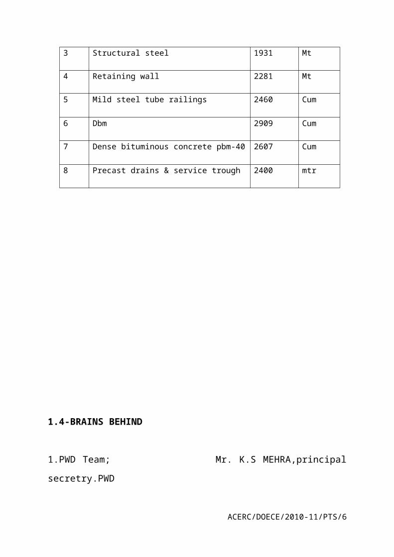
1.4-BRAINS BEHIND
1.PWD Team; Mr. K.S MEHRA,principal secretry.PWD
Mr.R.SUBRAMANIAN,E-in-C,PWD
Mr.A.K.SINGHAL.chief engineer.PWD
Mr.DEEPAKPANWAR,project Manager.PWD
Mr.BHUPENDRA KUMAR,executive engineer,PWD
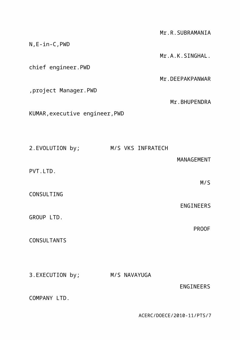
2.EVOLUTION by; M/S VKS INFRATECH
MANAGEMENT PVT.LTD.
M/S CONSULTING
ENGINEERS GROUP LTD.
PROOF CONSULTANTS
3.EXECUTION by; M/S NAVAYUGA
ENGINEERS COMPANY LTD.
FIGURE-1
DRAWING PLAN OF FLYOVER
ACERC/DOECE/2010-11/PTS/5
CHAPTER-2
SCOPE OF WORK:-
ACERC/DOECE/2010-11/PTS/6
The scope of work for the Grade Separator project for improvement of traffic system is
defined in this chapter. The construction work of total scheme of grade separator is decided
to be taken up in various phases due to diversion of existing traffic.
2.1-Underpass at Keshav Chowk
Phase I – Shifting of utilities.
Phase II – Diverting the traffic onto the slip roads and barricading the middle portion of the
existing road except the existing junction, construction of Diaphragm walls for this
barricaded portion of the underpass .
Phase III – Barricading and Construction of the deck slabs for the covered portions of the
underpass .
Phase IV – Diverting the cross traffic at the junction through the deck slab and complete the
construction of the rotary, Barricading the central portion of the junction and construction of
the diaphragm walls for the central open portion and Excavation of earth from the portion
between the diaphragm walls and construction of the base slab; construction of the service
roads, all finishing works, landscaping and electrical works .
2.2-Flyover on GT Road at Keshav Chowk near Shyam Lal College
Shahadra
ACERC/DOECE/2010-11/PTS/7

Phase I – Shifting of utilities, removing all existing islands and footpaths, widening
existing roads except at the junction of GT road, Road No 57 and Road No 65 and
diverting the traffic onto the new pavement (as per dwg. No.: TD015).
Phase II – Barricading of the central portion except at the junction of GT road, Road
No 57 and Road No 65 construction of Piled foundations and piers for the flyover (as
per dwg. No.: TD015).
Phase III – Construction of the superstructure for the viaduct spans, barricading the
obligatory portion and viaduct portion and construction of obligatory spans and
foundation and substructure for these viaducts, Barricading and construction of the
approach portion with R.E Walls and RCC retaining walls. (as per dwg. No.: TD016).
Construction of the central portion of the pedestrian subway shall be taken up in this
phase only.
Phase IV - Construction of the superstructures for the remaining viaducts and
construction of the busbays, all finishing works, landscaping and electrical works (as
per dwg no.: TD016).
2.3-The main activities in flyover construction are as follows:
Site clearance
Procurement of structural steel material and appointment of fabrication workshop
Construction of approach tracks, working platforms etc. for pile construction
Pile cap construction
Pier /Abutment construction
Construction of Steel concrete composite superstructure for flyover
Casting of RCC Crash Barrier
Reinforced Earth wall construction and filling of backfill material and road work
Installation of Expansion joints
Laying of Dense Bituminous concrete layer on deck slab
Fixing of longitudinal runner pipes, downtake pipes at pier locations with
drainage spouts and pipe railing on crash barrier.
Providing and laying of concrete wearing course using polypropylene fibres
(A.C.C. MARG Manufacture or equivalent) on bridge deck as per drawing.
ACERC/DOECE/2010-11/PTS/8

Cleaning of site
Thermoplastic lane marking on road surface and painting of railings and crash
barrier
consolidation, making sub grade, DLC and PQC
2.4-Broad Scope
The work under pertains to construction of the following components:
1.Construction of Main Flyover at Keshav Chowk along GT Road Shahadra: The
work shall consist of construction of embankments with Reinforced Earth wall &
RCC retaining walls, concrete pavement, Steel-Concrete composite plate girder
superstructure with pile foundations, piers/abutments, deck slab, expansion joints,
bearings, crash barriers etc.
i) And Construction of Main Underpass at Keshav Chowk on Road No 57 and 65:
The work shall consist of construction of the slip roads and service roads,
Diaphragm walls, concrete base slab, drainage, concrete pavement, crash barriers,
development of the aesthetics etc.
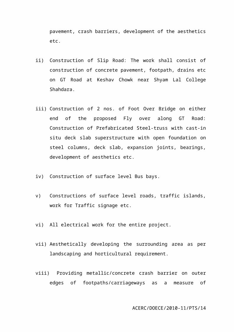
ii) Construction of Slip Road: The work shall consist of construction of concrete
pavement, footpath, drains etc on GT Road at Keshav Chowk near Shyam Lal
College Shahdara.
iii) Construction of 2 nos. of Foot Over Bridge on either end of the proposed Fly over
along GT Road: Construction of Prefabricated Steel-truss with cast-in situ deck
slab superstructure with open foundation on steel columns, deck slab, expansion
joints, bearings, development of aesthetics etc.
iv) Construction of surface level Bus bays.
v) Constructions of surface level roads, traffic islands, work for Traffic signage etc.
ACERC/DOECE/2010-11/PTS/9

vi) All electrical work for the entire project.
vii) Aesthetically developing the surrounding area as per landscaping and horticultural
requirement.
viii) Providing metallic/concrete crash barrier on outer edges of footpaths/carriageways
as a measure of pedestrian safety for aesthetics and pollution control etc.
ix) Construction of rotary and traffic light intersection, diversion roads to enable
smooth traffic flow during construction. Temporary Shifting of existing drains and
utilities etc.
x) Fabrication and providing barricading as per drawings for safe working.
CHAPTER-3
MATERIALS AND TESTING
ACERC/DOECE/2010-11/PTS/10

3.1 CEMENT
Ordinary Portland Cement of 43 Grade and 53 Grade conforming to IS: 8112 and IS:12269
respectively was used.
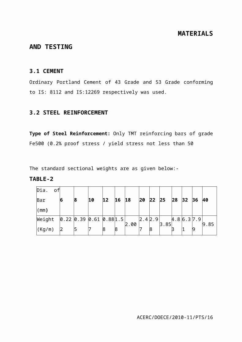
3.2 STEEL REINFORCEMENT
Type of Steel Reinforcement: Only TMT reinforcing bars of grade Fe500 (0.2% proof
stress / yield stress not less than 50
The standard sectional weights are as given below:-
TABLE-2
Dia. of Bar
(mm)6 8 10 12 16 18 20 22 25 28 32 36 40
Weight
(Kg/m) 0.222 0.395 0.617 0.888 1.58 2.00 2.47 2.98 3.85 4.83 6.31 7.99 9.85
3.3 POT-cum-PTFE Bearings
The pot-cum-ptfe bearings were designed as followings:-
ACERC/DOECE/2010-11/PTS/11

IRC: 83 (Part III): POT, POT CUM PTFE, PIN and Metallic Guide Bearings” shall form the
basis of bearing design. All the anchor sleeves, bolts, plates etc. shall be hot dip galvanized
@ 300 gm/m2.
FIGURE-2
Bearings used under steel girders
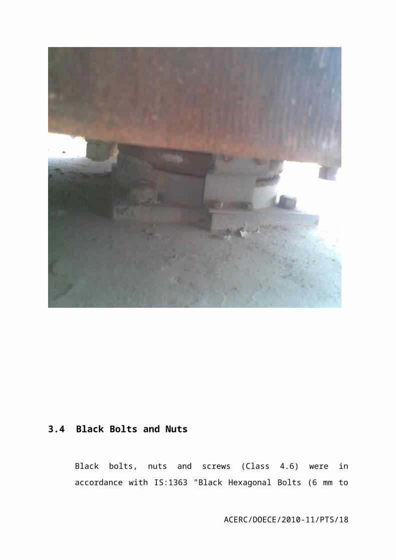
3.4 Black Bolts and Nuts
ACERC/DOECE/2010-11/PTS/12

Black bolts, nuts and screws (Class 4.6) were in accordance with IS:1363 "Black
Hexagonal Bolts (6 mm to 39 mm ) with "Nuts and Black Hexagonal screws (6 mm
to 24 mm)".
FIGURE-3
Bolts used to join girders
3.5 Coarse Aggregates
The nominal maximum size of aggregate used was of 20 mm for reinforced concrete works
However large size aggregate upto 40mm were also used for plain concrete
3.6 Fine Aggregate
ACERC/DOECE/2010-11/PTS/13
The fine aggregate used in concreting was of river sand pit sand, stone dust or other
approved sand
3.7 Admixtures
Type of Admixtures : Retarding admixtures based on Lingosus-Phonates with due
consideration to clause 5.2 and 5.3 of IS:7861 were used. Admixtures generating hydrogen
and nitrogen etc. were used
3.8 Expansion Joints
The expansion joints cater for expected movement and rotation of the structure at the joints
and providing smooth riding surface. It is also easy for inspection, maintenance and
replacement. The expansion joint were having robust, durable, water tight and able to safely
withstand all the imposed loads including the impact load from live load and other sources.
3.9 Testing
All the tests were done in front of engineer in charge at site and few tests were done by
external laboratories as these tests were not possible to conduct at site laboratory as all the
steel tests were done by Delhi government laboratory of steel testing. A laboratory was set up
at site for the tests of materials such as concrete, water, bitumen, water and cement.
Tests were done depending as per demand. Some tests were monthly, some were done
weekly n some tests were done on daily basis.
Monthly tests:-
Bulk density of coarse n fine aggregate.
Cement test(cement test was done as per lot). Following tests were done:-
1-soundness
2-fineness
3-compressive strength
4-initial and final setting time
ACERC/DOECE/2010-11/PTS/14

Weekly tests:-
1-compressive strength test of concrete
2-aggragate tests of both coarse and fine
3coarse aggregate tests-
Impact value
Crushing value
Elongation index
Daily tests:-
1-Concrete cube tests
2-seive analysis:-
a)20mm-aggregate
b)12.5mm-aggragate
c)silt content in fine aggregate
---Tests were conducted at labs on site once and then send to other labs for tests and
conformation.
---Tests were conducted in front of pwd officers and samples were passed by them.
STEEL TESTS
1-steel is tested by the manufacturing company and test reports come along the steel with all
the details of desired tests. like-tensile strength
2-steel is also send to another lab for conformation tests
3-it is not possible to conduct test on steel at site.
ACERC/DOECE/2010-11/PTS/15
Tests done under my observation-
1 concrete block test
Concrete m-40
After 7 days-
TABLE-3
Weight Load Strength
8255 910 40.44
8265 900 40.01
8280 930 41.33
8246 916 43.20
After 28 days
Concrete-m-40
TABLE-4
Weight Load Strength
8260 930 41.64
8320 1010 45.00
8150 1140 48.24
8400 1208 48.86
ACERC/DOECE/2010-11/PTS/16

Concrete m-35
After 7-days
TABLE-5
Weight Load Strength
8240 800 35.28
8215 830 37.09
8110 780 34.84
8202 820 36.25
Concrete m-35
After 28 days
TABLE-6
ACERC/DOECE/2010-11/PTS/17
Weight Load Strength
8360 900 40.10
8135 870 38.40
8275 1000 40.00
8215 780 37.09
COARSE AGGREGATE
10% Fine value
Size of aggregates-20mm
Source of aggr.-yamuna nagar
TABLE-7
DESCRIPTION SYM Test no.1 Test no.2
Weight of mould gm A 10390 10390
Weight of mould+sample B 14190 14215
Weight of sample C 3800 3825
Weight of sample passing
through 2.36mm IS sieve after
test
D 345 365
% of fine passing=D/C*100 % 9.07 9.54
Mean % of fines from two test at
X tonnes load
Y 9.305
Load required for 10%
fines=14*X/Y+4
26.305 tonnes
263.05 K.N
Where X=load in tonnes (25tonnes=250K.N)
The copy of test conducted is pasted at back.
BULK DENSITY
ACERC/DOECE/2010-11/PTS/18

TABLE-8
IMPACT VALUE TEST
Note- all aggregates passing through 12.5mm and 10.0mm sieve
Size of aggregate-20mm
TABLE-9
DESCRIPTION Sym Test no-1 Test no-2 Test no-3
Weight of mould (gm) A 724.6 724.6 724.6
Weight of mould+sample (gm) B 1049.6 1054.6 1058.6
Weight of sample (gm) C 325 330 334
Weight of sample passing through
2.36mm ISsieve after the test (gm)
D 46 42 48
Impact value=D/C*100 % 14.15 12.72 14.39
Average impact value(%) =13.59
ACERC/DOECE/2010-11/PTS/19
DESCRIPTION NOTATION SAMPLE-1 SAMPLE-2
Empty weight of cylindrical
metal measure(gm)
A 9280 9280
Weight of cylindrical metal
measure filled with
aggregate(gm)
B 31860 31805
Weight of aggregate (B-A) C 22580 22535
Volume of cylindrical metal
measure (cc)
D 14726 14726
Bulk density
aggregate=C/D*1000 kg/m
1533.34 1530.29
Average bulk density kg/m 1531.815
CHAPTER-4
DECK SLAB
4.1-General
The deck slabs of the flyover were constructed using the prestressing technique, so as to
make concrete strong in tension. The width of section is considerably reduced when
ptestressing is used. Less quantity of steel is used, but the technique is expensive than the
normal r.c.c pracities
Concrete used in span was of grade m-35
Steel girder were used at place of pre-casted slabs
Steel girders were of size 10m each and were joined with help of bolte and were made of size
30m
Shuttering was done on this girders only for casting slabs
Pile caps were used after setting up slabs between two sections of slabs
ACERC/DOECE/2010-11/PTS/20

FIGURE-4
Steel girders used at place of pre-casted slabs
ACERC/DOECE/2010-11/PTS/21

4.2-Use of hydraulic jack
FIGURE-5
Hydraulic jack
HYADRAULIC JACK APPLIED FOR TENSIONING OF STEEL WIRES
4.3-prestressing technology
This type of slab provides benefits of rapid construction, and improved structural
performance. The principal of working of pre-stressed slab’s is the wires are used in place of
steel bars. These wires after concreting are pulled with the help of hydraulic jack and tension
is created in wires and is locked at the end preventing the wires not to slip back.
ACERC/DOECE/2010-11/PTS/22

CHAPTER.5
CRASH BARRIER
Crash barriers are made at the end of slabs on both the sides so as to control the accidents.
The crash barriers are made up with concrete ant at the top metal railing was used so as for
good appearance. The crash barriers were also fitted with system for electric work as pipes
were putted while construction so to pass the electric wires for road lights etc.
Crash barriers were constructed up to a height of 1m.
Crash barriers were on both side of a slab.
FIGURE-6
Crash barrier
ACERC/DOECE/2010-11/PTS/23

FIGURE-7
Temperory form work done by welding on steel girders for crash barrier
ACERC/DOECE/2010-11/PTS/24

CHAPTER.6
ROAD WORK:
6.1 GRANULAR SUB-BASE
Type of material : The Material used for the work was natural sand, moorum, gravel,
crushed stone, or combination thereof depending upon the grading required.
Materials like crushed slag, crushed concrete, brick metal and kankar were allowed
with the specific approval of the Engineer-in-Charge.
Grading : While the gradings in respect of close-graded granular sub-base materials,
one each for maximum particle size of 75 mm, 53 mm and 26.5 mm, the
corresponding gradings for the coarse-graded materials for each of the three
maximum particle sizes are as per specifications..
6.2 COARSE AGGREGATES
Type of material : The coarse aggregates consist of crushed rock, crushed gravel or
other hard material retained on the 2.36mm sieve. They shall be clean, hard, durable,
of cubical shape, free from dust and soft of friable matter, organic or other deleterious
substances. Where the Contractor’s selected source of aggregates have poor affinity
for bitumen, as a condition for the approval of that source, the bitumen shall be
treated with an approved anti-stripping agent, as per the manufacture’s
recommendations, without additional payment. Before approval of the source, the
aggregates shall be tested for stripping.
6.3 FINE AGGREGATES
Type of material: Fine aggregates shall consist of crushed or naturally occurring
mineral material, or a combination of the two, passing the 2.36mm sieve and retained
on the 75 micron sieve. They shall be clean, hard durable, dry and free from dust, and
soft or friable matter, organic or other deleterious matter.
The fine aggregate shall have a sand equivalent value of not less than 50 when tested
in accordance with the requirement of IS:2720 (Part 37).
ACERC/DOECE/2010-11/PTS/25

The plasticity index of the fraction passing the 0.425 mm sieve shall not exceed 4
when tested in accordance with IS:2720 (Part 5).
6.4 LIME
Type of material: Lime for use as filler in bituminous mixes shall be commercial dry
lime, pre-slaked, and delivered to site in suitable packing. It shall have a purity of not
less than 80 per cent by weight of quick-lime (CaO) when tested in accordance with
IS:1514.
Storage of Lime: Lime shall be properly stored to avoid prolonged exposure to the
atmosphere and consequent carbonation.
6.5BITUMEN
1. Type of material : Bituminous materials shall be of the following two types, as
specified in the contract:
i Bituminous emulsion
ii Penetration grade bitumen
Bituminous emulsion The bituminous emulsion shall comply with the requirements of
IS:8887 and Penetration grade bitumen Penetration grade bitumen shall comply with
the requirements of IS:73. They are referred to by a single-figure designation. Thus,
grade 35 refers to a bitumen in the range of 30 to 40.
2. Polymer modified Bitumen: Polymer modified binder shall comply with the
requirements of IRC:SP-53-2002 and Elastomeric Thermoplastic Specifications.
The modifier shall be Styrene-Butadiene-Styrene, and the blending of the modifier
with bitumen shall be accomplished either in the refinery or an approved plant at
site capable of mixing the modifier and bitumen uniformly. The minimum content
of (SBS) Styrene-Butadiene-Styrene shall be 4% with appropriate sulphur content.
ACERC/DOECE/2010-11/PTS/26

The bitumen of required grade as specified conforming to IS:73-1992 with upto date
amendments and other relevant codes from the manufactuers of repute like Indian Oil
Corporation Ltd, Hindustan Petroleum Corporation Ltd. and Bharat Petroleum
Corporation Ltd. as approved by Ministry of Petroleum, Govt. of India and holding
licence to use ISI certificates mark for their products.
6.6 ROAD WORK – (FLEXIBLE PAVEMENT)
TABLE-10
PROFORMA FOR THE BITUMEN REGISTER RECEIPT
---------------------------------------------------------------------------------------------------------
Date of Qty Progressive Date of Qty. Total Balance Cont.’ JE’s
Receipt Received Total Issue Issued Issued in hand initial initials
1 2 3 4 5 6 7 8 9
---------------------------------------------------------------------------------------------------------
_____________________________________________________________________
---------------------------------------------------------------------------------------------------------
Item of Appx. Qty. Theoretical requirement Remarks of
work of of work of bitumen for work AE/AEE Ex. Eng.
Which issued done on each done on each day
6.7 SUB-GRADE CONSTRUCTION
It shall be ensured prior to actual execution that the borrow area material to be used in
the sub-grade satisfies the requirements of design CBR (not less than 5%, under
soaked condition). For the purposes of specifications, the top 500mm thick layer of
filling in the embankment (just below the sand drainage layer) over the entire
formation width and directly supporting the road pavement will be termed as
‘subgrade’.
Sub-grade shall be compacted and finished to the design strength consistent with other
physical requirements. The actual laboratory CBR values of constructed sub-grade
ACERC/DOECE/2010-11/PTS/27
shall be determined on remoulded samples. IRC: 37-1984 shall be referred to for
details.
The 500mm thick of the sub-grade shall be compacted to achieve at least 97% of
MDD at OMC.
6.8 GRANULAR SUB-BASE COURSE
This work shall consist of laying and compacting well-graded material on prepared
sub-grade in accordance with the requirements of these Specifications. The material
shall be laid in one or more layers as sub-base or lower sub-base and upper sub-base
(termed as sub-base hereinafter) as necessary according to lines, grades and cross-
sections shown on the drawings or as directed by the Engineer-in-Charge.
The granular sub-base (GSB) material shall be closed graded of grading I and III,
conforming to the requirements of clause 401 and table 400-1 of MORTH,
Specifications for Road and Bridge Works (4th Revision 2001).
6.9 WET MIX MACADAM BASE COURSE
The work shall consist of laying and compacting clean, crushed, graded aggregate and
granular material premixed with water, to a dense mass on a prepared subgrade/sub-
base/base or existing pavement as the case may be in accordance with the
requirements of these specifications. The material shall be laid in one or more layers
as necessary to lines, grade and cross section shown on the approved drawings or as
directed by the Engineer-in-charge. The laying of WMM layer shall be done using
paver only.
The wet mix macadam base course shall satisfy the requirements of clause 406 of
MORTH, Specifications for Road and Bridge Works. (4th revision 2001)
6.10 BITUMINOUS WORK
GENERAL
The contractor shall have to necessarily deploy self-propelled paver with electronic
sensor having suitable hydraulically operated screeds capable of spreading, tamping
ACERC/DOECE/2010-11/PTS/28

and finishing the mix true to the specified lines, grades and cross sections of the road.
The paver finisher shall have the following essential features :
i) Loading hoppers and suitable distributing mechanism.
ii) All drives having hydrostatic drive/control.
iii) The machine shall have a hydraulically extendable screed for appropriate
width requirement.
iv) The screed shall have tamping and vibrating arrangement for initial
compaction to the layer as it is spread without rutting or otherwise marring the
surface. It shall have adjustable amplitude and variable frequency.
v) The paver shall be equipped with necessary control mechanism so as to ensure
that the finished surface is free from surface blemishes.
vi) The paver shall be fitted with an electronic sensing device for automatic
leveling and profile control within the specified tolerances.
vii) The screed shall have the internal heating arrangement.
viii) The paver shall be capable of laying 2.5 to 4.0 m width in service road and
4.0 to 7.0m width on main carriageway as per site requirement.
ix) The paver shall be so designed as to eliminate skidding/slippage of the tyres
during operation.
x) The contractor shall have to necessarily deploy the road rollers, for BM, DBM
& BC for their compaction as per relevant MORT&H specifications.
Mix shall be prepared in a computerized hot mix plant of adequate capacity and
capable of yielding a mix of proper and uniform quality with thoroughly coated
aggregate. Hot Mix Plant shall be preferably of batch mix type with electronic load
ACERC/DOECE/2010-11/PTS/29

sensor device. The requirement of clause 504.3.4 of MoRT&H Specifications for
Road and Bridge Works (Fourth Revision) 2001 shall be strictly adhered to.
6.11 PRIME COAT
The work shall consists of the application of a single coat of low viscosity liquid
bituminous material to a porous granular surface preparatory to the superimposition of
bituminous mix material. The work shall execute in accordance with clause 502 and
sub clause there to of MoRT&H Specifications for Road and Bridge Works (Fourth
Revision) 2001.
The emulsified bitumen for prime coat shall be medium setting conforming to
IS:8887-1995. The bitumen emulsion shall be brought at site in one lot in sealed
drums and shall be got verified and checked by the representative of Engineer-in-
Charge before its use. After priming coat the road can be opened to the traffic as
directed by the engineer in charge.
6.12 TACK COAT
The work shall consist of application of single coat of low viscosity liquid bituminous
material to an existing road surface preparatory to another bituminous construction
over it. The binder used for tack coat shall be bitumen of suitable grade as specified in
nomenclature of item.
a) The emulsified bitumen for tack coat on road shall be medium setting (MS) type
conforming to IS: 8887-1995. The bitumen emulsion shall be brought at site in one lot
in sealed drums and shall be got verified and checked by the representative of
Engineer-in-Charge before its use. The work shall be done strictly in accordance with
clause 503 and sub-clauses thereto of MORT&H specifications for Roads & Bridges
work (Fourth Revision), 2001.
b) Cleaning and Preparation of the Surface: The surface on which the tack coat is to be
applied shall be clean and free from dust, dirt and any extraneous material and be
otherwise prepared in accordance with the requirements of clause 501.8 and 902 of
MORT&H Specifications for Road and Bridge Works (Fourth Revision). Immediately
before the application or the tack coat, the surface shall be swept clean with a
mechanical broom and high pressure jet or by other means as directed by the
Engineer-in-Charge.
ACERC/DOECE/2010-11/PTS/30

6.13 BITUMINOUS MACADAM
The work shall consists of constructing a single layer of specified compacted
thickness of bituminous macadam consisting of crushed stone aggregate mixed with
bituminous binder laid immediately after mixing on a previously prepared base in
accordance with the requirement of specification as laid down in clause-504 and sub
clause thereto of MORT&H Specifications for Road and Bridge Works (Fourth
Revision) 2001 and as directed by the Engineer-in-Charge.
Material
i) Bitumen
Bitumen shall confirm to grade and quantity as specified in nomenclature of item.
ii) Aggregate
Aggregate shall consist of crushed stone aggregate confirming to grading and
specification as laid down in sub clause 504.2.2 to 504.2.5 of MORT&H
Specifications for Road and Bridge Works (Fourth Revision) 2001. The grading shall
conform to grading 2 of Table 500-4.
The contract unit rate for the Bituminous Macadam shall be payment in full for
carrying out all the required operations as specified, and shall include, but not
necessarily limited to all component listed in 501.8.8.2 (i) to (xi) as MORT&H
Specifications for Road and Bridge Works (Fourth Revision) 2001. The rate shall
include the provision of bitumen in mix design @ 3.5% by weight of total mix with
provision that variation of quantity on minus side shall be recovered @ Rs. 25,200/-
per MT of bitumen less used as per design mix. However, no extra payment would be
admissible for use of extra bitumen if the variation is on higher side i.e. beyond 3.5%
of weight of total mix.
6.14 DENSE BITUMINOUS MACADAM
The work shall consists of constructing dense bituminous macadam of specified
compacted thickness consisting of crushed stone aggregate mixed with bituminous
binder laid immediately after mixing on a previously prepared base in accordance
with the requirement of specification as laid down in clause 507 and sub clause
ACERC/DOECE/2010-11/PTS/31

thereto of MORT&H Specifications for Road and Bridge Works (Fourth Revision)
2001 and as directed by the Engineer-in-Charge.
Material
i) Bitumen
Bitumen shall confirm to grade and quantity as specified in nomenclature of item.
ii)Aggregate
Aggregate shall consist of crushed stone aggregate confirming to grading and
specification as laid down in sub-clause-507.2.2 to 507.2.5 of MoRT&H
Specifications for Road and Bridge Works (Fourth Revision) 2001. The grading shall
conform to grading of Table 500-10/
iii)Filler
Filler shall consist of hydrated lime of grade & specification conforming to clause
507.2.4 of MORT&H Specification for Roads & Bridges.
The contract unit rate for the Dense Bituminous Macadam shall be payment in full for
carrying out all the required operations as specified, and shall include, but not
necessarily limited to all component listed in 501.8.8.2 (i) to (xi) as MORT&H
Specifications for Road and Bridge Works (Fourth Revision) 2001. The rate shall
include the provision of bitumen in mix design @ 5.0% by weight of total mix with
provision that variation of quantity on minus side shall be recovered @ Rs 25,200/-
per M.T. of bitumen less use as per design mix. However, no extra payment would be
admissible for use of extra bitumen if the variation is on higher side i.e. beyond 5% of
weight of total mix.
6.15 BITUMINOUS CONCRETE
The work shall consist of constructing a single layer of specified compacted thickness
of bituminous concrete consisting of crushed stone aggregate mixed with bituminous
binder to serve as wearing course laid immediately after mixing on a previously
prepared base in accordance with the requirements of specifications as laid down in
clause 509 and sub-clauses thereto of MORT&H Specifications for Road and Bridge
Works (Fourth Revision) 2001 and as directed by Engineer-in-Charge.
Material
i) Polymer Modified Bitumen (PMB-40)
ACERC/DOECE/2010-11/PTS/32

Bitumen shall conform to grade and quantity as specified in nomenclature of item.
ii) Aggregate
Aggregates shall consist of crushed stone aggregate conforming to grading &
specifications as laid down in sub-clause 509.2.2 to 509.2.5 of MORT&H
specifications for Road & Bridges work(4th revision 2001). Only crushed stone
aggregate shall be allowed. The grading shall conform to grading 1 of Table 500-
18 of MORT&H Specifications for Road and Bridge Works (Fourth Revision)
2001.
iii) Filler
Filler shall consist of hydrated lime of grade & specification conforming to clause
509.2.4 of MORT&H Specification for Roads & Bridges(4th revision 2001).
iv) Rate
The contract unit rate for the Dense Bituminous Concrete using modified bitumen
(PMB-40) shall be payment in full for carrying out all the required operations as
specified, and shall include, but not necessarily limited to all component listed in
501.8.8.2 (i) to (xi) of MORT&H Specifications for Road and Bridge Works
(Fourth Revision) 2001. The rate shall cover the provision of modified bitumen
(PMB-40) in mix design @ 5.5% by weight of total mix with provision that
variation of quantity on minus side shall be recovered @ Rs. 31,800/- per M.T. of
modified bitumen, less used as per design mix. However, no extra payment would
be admissible for use of extra modified bitumen if the variation is on higher side
i.e. beyond 5.5% of weight of total mix.
6.16 COMPACTION
The degree of compaction for the various bituminous layers shall be established by
taking CORE from the laid bituminous layer. The bill of the contractor shall be paid
only if the same qualifies as per the specifications / requirements. Sand replacement
method for verifying the degree of compaction of laid bituminous layers will not be
allowed
ACERC/DOECE/2010-11/PTS/33

6.17 C.C. KERB STONES
Procurement
Pre-cast C.C. kerb stones conforming to M-35 grade of concrete and size as
mentioned in the nomenclature of items, shall be procured only from reputed
manufacturer approved by Engineer-in-Charge. The plant/ factory to be approved by
the Engineer in Charge shall strictly adhere to following norms before supply is
entrusted to them:
(i) The mix shall be prepared in batch mix plant only.
(ii) The plant shall remain open to inspection at any time for above lot.
(iii) A suitable vibrating and curing mechanism shall be maintained to ensure the
quality as desired.
(iv) Minimum grade of concrete shall be M-35 i.e. compressive characteristic
strength of concrete at 28 days shall not be less than 35 N/mm2.
(v) Proper Logo of manufacture shall be engraved on each kerb stone.
(vi) The contractor shall provide original challan / voucher as a proof of having the
material purchased from the approved manufacturer. The original challan/voucher
shall be returned after verification and making necessary endorsement.
Laying
Before laying at site compressive strength test in accordance with specifications shall
be mandatory. Laying shall be as per specifications and direction of Engineer-in-
Charge.
Sampling And Testing
The contractor shall have to obtain and furnish test certificates issued by
manufacture to the Engineer-in-Charge in respect of material purchased by
him. However, sample shall be collected, at discretion of Engineer-in-Charge
and got tested as per relevant B.I.S. Codes and specifications from the
laboratory provided by him.
The contractor shall supply, free of cost, the required samples of kerb stones
for testing. Cost of tests shall also be borne by the contractor.
ACERC/DOECE/2010-11/PTS/34

In case the test results reveal that the kerb stones procured by the contractor do
not conform to the relevant B.I.S. Codes and specifications, the same lot shall
stand rejected and the contractor shall have to remove that material from site at
his own cost within a week’s time of written order from Engineer-in-Charge to
do so.
For the execution of any items of work where any incidental work is actually
required but not specifically stated in the tender, it is to be understood that the
rate quoted by the contractor shall cover such charges also and nothing extra
on account of such incidental charges, if any, shall be paid.
Inserts And Embedments
Various steel inserts and embedments are required under the contract to be
fabricated, galvanized to minimum 200 gm/sqm, positioned and secured firmly into
place inside the formwork prior to concrete being poured. There are also
requirements of jointing, threading, bolting and welding inserts and embedments of
different concrete and structural steel elements in order to establish structural
continuity and connection. Great care shall be exercised by the contractor in
executing all aspects of the work related to inserts and embedments, including
tolerances, primers, galvanizing etc. so that the final assembly of the concrete
elements can meet satisfactorily the requirements intended in the structure.
Void Former In Concrete
The corrugated spiral tubes void formers shall be of galvanised steel 0.7mm (min)
strips with 4-ply spiral lock seal which runs on the external side manufactured by
specialised agencies using high precision machines. Various matching tube fitting like
slip joint couplings, end blockers etc. and other support systems shall be as per
supplier details. The void formers shall be procured form any of the suppliers listed in
Annexure-A
ACERC/DOECE/2010-11/PTS/35

CHAPTER-7
DIAPHGRAM WALL
7.1 STEEL REINFORCEMENT FOR STRUCTURE
GENERAL
The reinforcement bars bent and fixed in position shall be free from rust or scales,
chloride contamination and other corrosion products. Effective methods of cleaning
will have to be used so that the steel is free from rust, scales and contamination. The
decision of Engineer-in-Charge in this regard shall be final & binding.
BENDING OF REINFORCEMENT
Bending of reinforcement shall be done as per bar bending schedule to be prepared and
got approved by the contractor from Engineer-in-Charge or his authorised
representative prior to commencement of work. The bar cutting and bending for 16mm
and above diameters shall be done on bar cutting and bending machine only.
PLACING OF REINFORCEMENT
Reinforcement left projecting from newly placed concrete shall be supported in such a
way that there is no sag or risk of damage to the newly placed concrete. The projecting
bars that are likely to be exposed for a long time shall be protected by a coat of neat
cement wash. These shall be thoroughly cleaned and wire brushed before depositing
fresh concrete around it. No reinforcement bar shall remain exposed or projecting out
of the concrete surface. These shall be removed or treated in a manner as directed by
Engineer-in-Charge. The unwanted projected reinforcement bars shall be cut below the
finished surface and the cut end painted with epoxy paint. Thereafter the surface shall
be repaired to match the colour, texture or pattern of adjoining concrete to the
satisfaction of Engineer-in-Charge.
.
ACERC/DOECE/2010-11/PTS/36

BAR SPLICES
The location of joints in continuous reinforcing bars, not shown in drawings, shall be
submitted to the Engineer-in-Charge for acceptance. If nothing contrary has been
specified, the number of bars to be joined in any cross section shall not exceed one-
third of the total.
7.2 Drilling Mud (Bentonite Slurry)
The drilling mud shall be used at least 1.5m above from the level of sub-soil water
depending upon site conditions and the hole shall then be always kept almost full with
the fluid which shall preferably be kept in motion during boring operation. The
density and composition of the fluid shall be such as to suit the requirements of the
ground conditions and maintain the fine materials from the boring in suspension.
Bentonite suspension shall meet the following specifications:
i) Density = 1.05 g/cc
ii) Marsh Cone Viscosity between 30 and 40
iii) The pH value between 9.5 and 12
iv) The silt content < 1%
v) The liquid limit of bentonite not less than 400%
The level of drilling mud shall be maintained at least 1.5m above the contemporary
ground water level. The bentonite slurry shall not be allowed to be discharged into
any nallah/drain or on the ground. The waste slurry shall be removed by
tanker/vehicles as directed by Engineer-in-Charge. In order to avoid collapse of
upper soft soil into the borehole, temporary liner of thickness not less than 6 mm shall
be provided up to at least 5 m from the existing ground level. The liner shall be
provided by hydraulically operated mechanism. After concreting of pile the liner shall
be extracted by vibrators or jacking.
ACERC/DOECE/2010-11/PTS/37
7.3 Tremie Method
The tremie pipes and funnel shall be filled with concrete and lifted 15 cm above the
bottom of the hole before releasing the concrete column in order to facilitate flushing
it out. The concrete levels in the tremie shall be checked for every few feet in order to
note the difference, if any, between the theoretical quantity that should have been
placed and actual quantity that has gone in. This serves when fixing the position of
over cut during pouring.
In case the actual quantity of concrete poured in the D’wall hole is less than 90%
of the theoretical quantity of concrete for the D’wall, the D’wall shall be
subjected to rejection.
The diameter of tremie pipe shall be 200mm minimum and the funnel should be
capable of holding 0.4 cum of concrete.
Following rules were strictly observed during the tremie method, cited above
i) The concreting of a d’wall must be completed in one continuous operation.
ii) The concrete shall be coherently rich in cement and having slump in the range
of 150mm to 200mm.
iii) A temporary liner should be installed for at least top 5 m depth of soil as
mentioned elsewhere in the tender documents which would ensure that
fragments of comparatively loose soil cannot drop from the sides into the
concrete. Arrangement for lowering and withdrawal of temporary liner should
be independent of those for the tremie pipe etc.
iv) The tremie shall be large enough in order to cater for the size of aggregates
thereby allowing a smooth uninterrupted flow of concrete. For instance, a
tremie of 200 mm diameter shall suffice the requirements with 20 mm
ACERC/DOECE/2010-11/PTS/38
aggregate. The tremie should be of robust construction conforming to the
approved standards.
v) The first charge of concrete shall be placed with a sliding plug pushed down
the tube ahead of it to prevent mixing of concrete and water/bentonite slurry.
However, the plug shall not be left in the concrete as a lump.
vi) The tremie pipe shall always penetrate deep enough (at least 1m) into the
concrete with an adequate margin of safety against accidental withdrawal.
vii) The pile shall be concreted wholly by tremie and the method of deposition
shall not be changed part way up the pile in order to prevent the latency from
being entrapped within the d’wall
viii) The tremie shall essentially be water-tight in order to avoid mixing of bore
fluid with the concrete.
ix) All tremie tubes shall be scrupulously cleaned after every use.
x) To ensure compaction of concrete by hydraulic static head, rate of placing of
concrete in the pile shaft shall not be less than 6m length of d’wall per hour.
Normally the concreting of the d’wall shall be uninterrupted. In case, under the
unavoidable circumstances, the operation has to suspend for a period of 6 hours
maximum the tremie shall not be taken out of concrete. Instead it shall be raised and
lowered slowly from time to time which would prevent the concrete around the tremie
from setting. Concreting should be resumed by introducing a little richer concrete (5%
additional cement) with a higher slump for easy displacement of the partly set
concrete.
ACERC/DOECE/2010-11/PTS/39

FIGURE-12
Tremie method
ACERC/DOECE/2010-11/PTS/40

7.4-Machine used for digging fame for d’wall
FIGURE-9
Machine for d’wall
ACERC/DOECE/2010-11/PTS/41

PLACING OF DIAPHAGRAM WALL REINFORCEMENT
FIGURE-10
D’wall steel web placing
STEEL REINFORCEMENT MESH BEING PLACED IN FRAME DUGGED FOR
D’WALL
ACERC/DOECE/2010-11/PTS/42

STEEL MESH HALF INSIDE THE DUGGED FRAME
FIGURE-11
Placing of steel web
ACERC/DOECE/2010-11/PTS/43

STEEL WEB ON STAGE OF COMPLITION
FIGURE-12
Placing complition
STEEL MESH COMPLETELY GONE INSIDE THE DUGGED FRAME FOR
D’WALL
ACERC/DOECE/2010-11/PTS/44
FIGURE-13
Crab of d’wall machine
MACHINE USED FOR DIGGING D’WALL FRAME OF SIZE-
5M*600CM
ACERC/DOECE/2010-11/PTS/45

Figure-14
Shuttering on girders for slab
ACERC/DOECE/2010-11/PTS/46

Figure-15
Casting of slab
ACERC/DOECE/2010-11/PTS/47

Figure-16
Arrangement for electric work
ACERC/DOECE/2010-11/PTS/48
Figure-17
Concrete plant
ACERC/DOECE/2010-11/PTS/49
Figure-18
View of steel web used for d’wall section
ACERC/DOECE/2010-11/PTS/50

CONCLUSION
Technical education means the education regarding the techniques and
techniques are nothing but the practical approach of doing something. So, in the
curriculum of technical studies it becomes necessary to have the practical
knowledge along with the theoretical one.
The theory is not just applied in the field in the same way as it appears
in the book but it is applied in the most optimum but the feasible way. So, the
training also enables us to get the practical aspects of the theory, and it also tells
us the practical problems which generally occur in the field and are to be dealt
by the engineering decisions.
So, in a nut shell it can be said that the practical training is a very
important part of our curriculum which connects us with the actual scenario of
our field and lets us develop the practical approach of thinking, analyzing and
implementing any problem so it should be taken very sincerely.
ACERC/DOECE/2010-11/PTS/51
LIST OF REFERENCE
1. Guidance provided by the pwd officer, supervisor & other staff member
2. IS 456:2000
Indian Standard
PLAIN AND REINFORCED CONCRETE CODE OF PRATICE
3. BOOKS:-
(a) R.C.C – B.C.PUNMIA
(b) CONCRETE – M.S.SHETTY
(c) BUILDING CONSTRUCTION - B.C.PUNMIA
4. Tender document and aggrement copy.
ACERC/DOECE/2010-11/PTS/52