966H AND 972H WHEEL LOADERS - PersianGIG · 2014-05-02 · 966H AND 972H WHEEL LOADERS Maintenance...
60
966H AND 972H WHEEL LOADERS Maintenance Intervals Excerpted from Operation & Maintenance Manual (SEBU7887-12) ® © 2010 Caterpillar All Rights Reserved ® SAFETY.CAT.COM™
Transcript of 966H AND 972H WHEEL LOADERS - PersianGIG · 2014-05-02 · 966H AND 972H WHEEL LOADERS Maintenance...

966H AND 972HWHEEL LOADERSMaintenance Intervals
Excerpted from Operation & Maintenance Manual (SEBU7887-12)
®© 2010 CaterpillarAll Rights Reserved
®
SAFETY.CAT.COM™
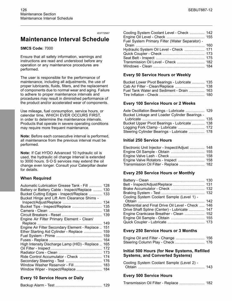
126 SEBU7887-12Maintenance SectionMaintenance Interval Schedule
i03772567
Maintenance Interval ScheduleSMCS Code: 7000
Ensure that all safety information, warnings andinstructions are read and understood before anyoperation or any maintenance procedures areperformed.
The user is responsible for the performance ofmaintenance, including all adjustments, the use ofproper lubricants, fluids, filters, and the replacementof components due to normal wear and aging. Failureto adhere to proper maintenance intervals andprocedures may result in diminished performance ofthe product and/or accelerated wear of components.
Use mileage, fuel consumption, service hours, orcalendar time, WHICH EVER OCCURS FIRST,in order to determine the maintenance intervals.Products that operate in severe operating conditionsmay require more frequent maintenance.
Note: Before each consecutive interval is performed,all maintenance from the previous interval must beperformed.
Note: If Cat HYDO Advanced 10 hydraulic oil isused, the hydraulic oil change interval is extendedto 3000 hours. S·O·S services may extend the oilchange even longer. Consult your Caterpillar dealerfor details.
When Required
Automatic Lubrication Grease Tank - Fill ............ 128Battery or Battery Cable - Inspect/Replace ........ 130Bucket Cutting Edges - Inspect/Replace ............ 133Bucket Hinge and Lift Arm Clearance Shims -Inspect/Adjust/Replace ..................................... 134Bucket Tips - Inspect/Replace ............................ 135Camera - Clean .................................................. 138Circuit Breakers - Reset ...................................... 139Engine Air Filter Primary Element - Clean/Replace ............................................................. 149Engine Air Filter Secondary Element - Replace .. 151Ether Starting Aid Cylinder - Replace ................. 159Fuel System - Prime ........................................... 159Fuses - Replace .................................................. 164High Intensity Discharge Lamp (HID) - Replace .. 165Oil Filter - Inspect ................................................ 172Radiator Core - Clean ......................................... 173Ride Control Accumulator - Check ..................... 174Secondary Steering - Test .................................. 176Window Washer Reservoir - Fill .......................... 183Window Wiper - Inspect/Replace ........................ 184
Every 10 Service Hours or Daily
Backup Alarm - Test ............................................ 129
Cooling System Coolant Level - Check .............. 142Engine Oil Level - Check .................................... 155Fuel System Primary Filter (Water Separator) -Drain ................................................................. 160Hydraulic System Oil Level - Check ................... 171Quick Coupler - Check ........................................ 173Seat Belt - Inspect .............................................. 175Transmission Oil Level - Check .......................... 182Windows - Clean ................................................. 184
Every 50 Service Hours or Weekly
Bucket Lower Pivot Bearings - Lubricate ............ 135Cab Air Filter - Clean/Replace ............................ 138Fuel Tank Water and Sediment - Drain ............... 163Tire Inflation - Check ........................................... 180
Every 100 Service Hours or 2 Weeks
Axle Oscillation Bearings - Lubricate .................. 129Bucket Linkage and Loader Cylinder Bearings -Lubricate ........................................................... 135Bucket Upper Pivot Bearings - Lubricate ............ 138Logging Fork Clamp - Lubricate ......................... 172Steering Cylinder Bearings - Lubricate ............... 178
Initial 250 Service Hours
Electronic Unit Injector - Inspect/Adjust .............. 148Engine Oil Sample - Obtain ................................ 155Engine Valve Lash - Check ................................. 158Engine Valve Rotators - Inspect ......................... 158Transmission Oil Filter - Replace ........................ 182
Every 250 Service Hours or Monthly
Battery - Clean .................................................... 130Belt - Inspect/Adjust/Replace .............................. 131Brake Accumulator - Check ................................ 132Braking System - Test ......................................... 132Cooling System Coolant Sample (Level 1) -Obtain ............................................................... 142Differential and Final Drive Oil Level - Check ..... 146Drive Shaft Spline (Center) - Lubricate ............... 147Engine Crankcase Breather - Clean ................... 152Engine Oil Sample - Obtain ................................ 155Quick Coupler - Lubricate ................................... 173
Every 250 Service Hours or 3 Months
Engine Oil and Filter - Change ........................... 156Steering Column Play - Check ............................ 176
Initial 500 Hours (for New Systems, RefilledSystems, and Converted Systems)
Cooling System Coolant Sample (Level 2) -Obtain ............................................................... 143
Every 500 Service Hours
Transmission Oil Filter - Replace ........................ 182
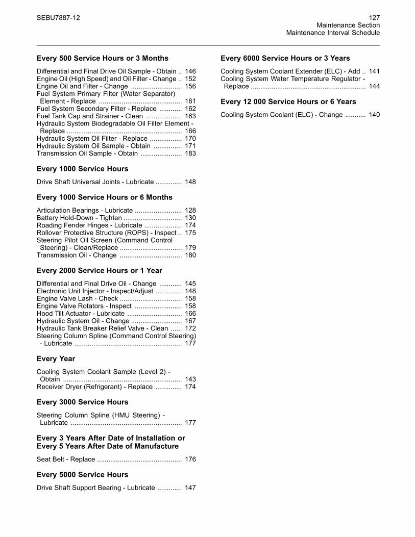
SEBU7887-12 127Maintenance Section
Maintenance Interval Schedule
Every 500 Service Hours or 3 Months
Differential and Final Drive Oil Sample - Obtain .. 146Engine Oil (High Speed) and Oil Filter - Change .. 152Engine Oil and Filter - Change ........................... 156Fuel System Primary Filter (Water Separator)Element - Replace ............................................ 161Fuel System Secondary Filter - Replace ............ 162Fuel Tank Cap and Strainer - Clean ................... 163Hydraulic System Biodegradable Oil Filter Element -Replace ............................................................. 166Hydraulic System Oil Filter - Replace ................. 170Hydraulic System Oil Sample - Obtain ............... 171Transmission Oil Sample - Obtain ...................... 183
Every 1000 Service Hours
Drive Shaft Universal Joints - Lubricate .............. 148
Every 1000 Service Hours or 6 Months
Articulation Bearings - Lubricate ......................... 128Battery Hold-Down - Tighten ............................... 130Roading Fender Hinges - Lubricate .................... 174Rollover Protective Structure (ROPS) - Inspect .. 175Steering Pilot Oil Screen (Command ControlSteering) - Clean/Replace ................................. 179Transmission Oil - Change ................................. 180
Every 2000 Service Hours or 1 Year
Differential and Final Drive Oil - Change ............ 145Electronic Unit Injector - Inspect/Adjust .............. 148Engine Valve Lash - Check ................................. 158Engine Valve Rotators - Inspect ......................... 158Hood Tilt Actuator - Lubricate ............................. 166Hydraulic System Oil - Change ........................... 167Hydraulic Tank Breaker Relief Valve - Clean ...... 172Steering Column Spline (Command Control Steering)- Lubricate ......................................................... 177
Every Year
Cooling System Coolant Sample (Level 2) -Obtain ............................................................... 143Receiver Dryer (Refrigerant) - Replace .............. 174
Every 3000 Service Hours
Steering Column Spline (HMU Steering) -Lubricate ........................................................... 177
Every 3 Years After Date of Installation orEvery 5 Years After Date of Manufacture
Seat Belt - Replace ............................................. 176
Every 5000 Service Hours
Drive Shaft Support Bearing - Lubricate ............. 147
Every 6000 Service Hours or 3 Years
Cooling System Coolant Extender (ELC) - Add .. 141Cooling System Water Temperature Regulator -Replace ............................................................. 144
Every 12 000 Service Hours or 6 Years
Cooling System Coolant (ELC) - Change ........... 140
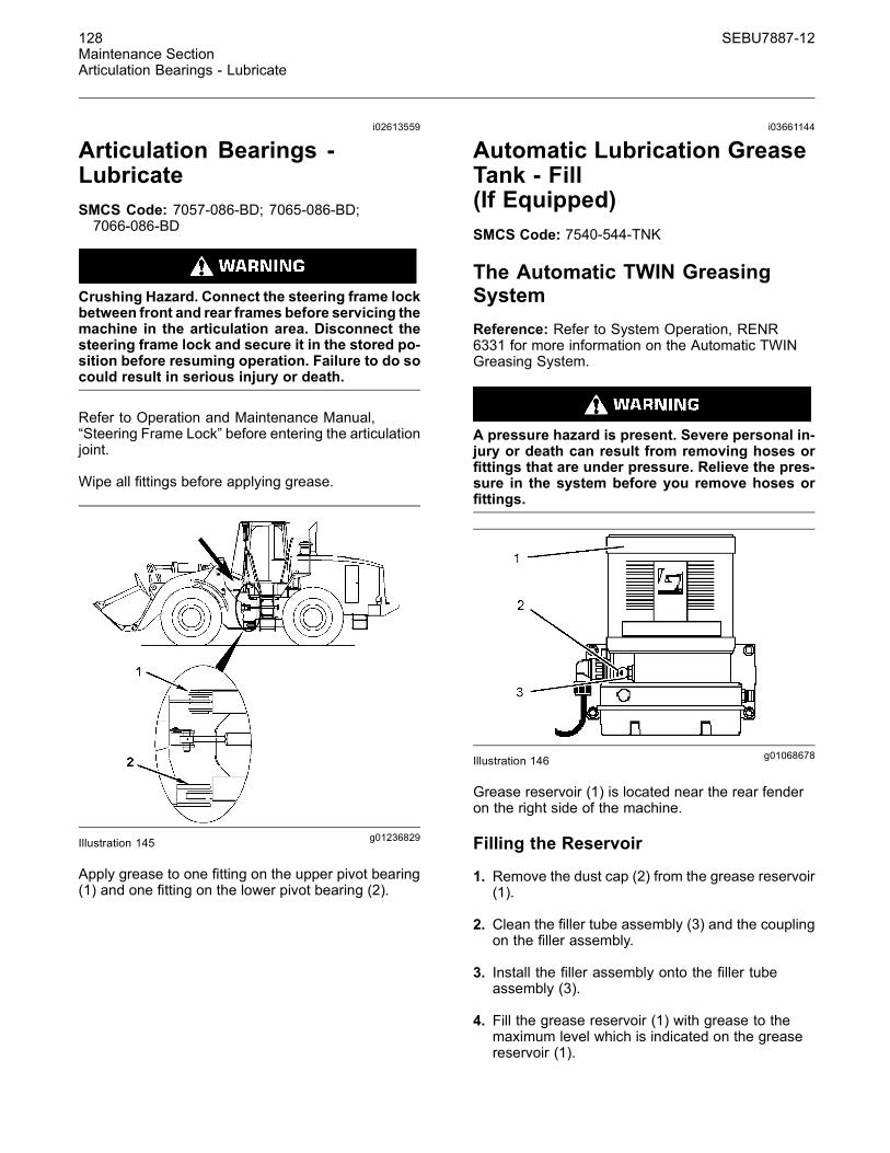
128 SEBU7887-12Maintenance SectionArticulation Bearings - Lubricate
i02613559
Articulation Bearings -LubricateSMCS Code: 7057-086-BD; 7065-086-BD;7066-086-BD
Crushing Hazard. Connect the steering frame lockbetween front and rear frames before servicing themachine in the articulation area. Disconnect thesteering frame lock and secure it in the stored po-sition before resuming operation. Failure to do socould result in serious injury or death.
Refer to Operation and Maintenance Manual,“Steering Frame Lock” before entering the articulationjoint.
Wipe all fittings before applying grease.
g01236829Illustration 145
Apply grease to one fitting on the upper pivot bearing(1) and one fitting on the lower pivot bearing (2).
i03661144
Automatic Lubrication GreaseTank - Fill(If Equipped)SMCS Code: 7540-544-TNK
The Automatic TWIN GreasingSystemReference: Refer to System Operation, RENR6331 for more information on the Automatic TWINGreasing System.
A pressure hazard is present. Severe personal in-jury or death can result from removing hoses orfittings that are under pressure. Relieve the pres-sure in the system before you remove hoses orfittings.
g01068678Illustration 146
Grease reservoir (1) is located near the rear fenderon the right side of the machine.
Filling the Reservoir
1. Remove the dust cap (2) from the grease reservoir(1).
2. Clean the filler tube assembly (3) and the couplingon the filler assembly.
3. Install the filler assembly onto the filler tubeassembly (3).
4. Fill the grease reservoir (1) with grease to themaximum level which is indicated on the greasereservoir (1).

SEBU7887-12 129Maintenance Section
Axle Oscillation Bearings - Lubricate
Reference: For the correct type of grease, referto Operation and Maintenance Manual, “LubricantViscosities”.
5. Remove the filler assembly and install the dustcap (2).
i03657089
Axle Oscillation Bearings -LubricateSMCS Code: 3268-086-BD; 3278-086-BD
Crushing Hazard. Connect the steering frame lockbetween front and rear frames before servicing themachine in the articulation area. Disconnect thesteering frame lock and secure it in the stored po-sition before resuming operation. Failure to do socould result in serious injury or death.
Refer to Operation and Maintenance Manual,“Steering Frame Lock” before entering the articulationjoint.
g01103093Illustration 147
Open the access panel on the right side of themachine in front of the steps.
g01105565Illustration 148
Wipe all fittings before lubricating.
Grease fitting (1) will lubricate the axle pivot bearingthat is on the front of the rear axle. Grease fitting (2)will lubricate the axle pivot bearing that is on the rearof the rear axle.
Note: 5P-0960 Molybdenum Grease is preferred.1P-0808 Multipurpose Grease grease may be used.
i02375125
Backup Alarm - TestSMCS Code: 7406-081
The backup alarm is on the rear of the machine.
In order to test the alarm for proper functioning, turnthe engine start switch to the ON position.
Apply the service brake. Place the transmission intoREVERSE.
The backup alarm should sound immediately.The backup alarm will continue to sound untilthe transmission is placed intoNEUTRAL or intoFORWARD.
g01043892Illustration 149
130 SEBU7887-12Maintenance SectionBattery - Clean
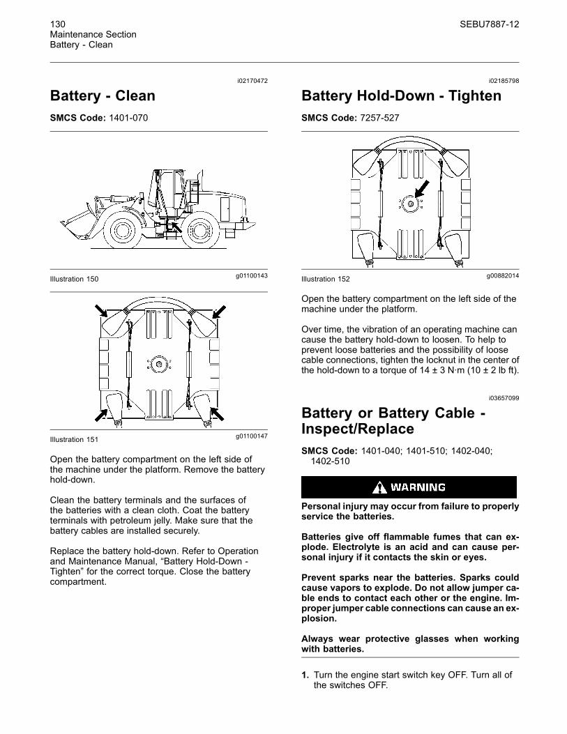
i02170472
Battery - CleanSMCS Code: 1401-070
g01100143Illustration 150
g01100147Illustration 151
Open the battery compartment on the left side ofthe machine under the platform. Remove the batteryhold-down.
Clean the battery terminals and the surfaces ofthe batteries with a clean cloth. Coat the batteryterminals with petroleum jelly. Make sure that thebattery cables are installed securely.
Replace the battery hold-down. Refer to Operationand Maintenance Manual, “Battery Hold-Down -Tighten” for the correct torque. Close the batterycompartment.
i02185798
Battery Hold-Down - TightenSMCS Code: 7257-527
g00882014Illustration 152
Open the battery compartment on the left side of themachine under the platform.
Over time, the vibration of an operating machine cancause the battery hold-down to loosen. To help toprevent loose batteries and the possibility of loosecable connections, tighten the locknut in the center ofthe hold-down to a torque of 14 ± 3 N·m (10 ± 2 lb ft).
i03657099
Battery or Battery Cable -Inspect/ReplaceSMCS Code: 1401-040; 1401-510; 1402-040;1402-510
Personal injury may occur from failure to properlyservice the batteries.
Batteries give off flammable fumes that can ex-plode. Electrolyte is an acid and can cause per-sonal injury if it contacts the skin or eyes.
Prevent sparks near the batteries. Sparks couldcause vapors to explode. Do not allow jumper ca-ble ends to contact each other or the engine. Im-proper jumper cable connections can cause an ex-plosion.
Always wear protective glasses when workingwith batteries.
1. Turn the engine start switch key OFF. Turn all ofthe switches OFF.
SEBU7887-12 131Maintenance Section
Belt - Inspect/Adjust/Replace
2. Turn the battery disconnect switch OFF. Removethe key.
3. Disconnect the negative battery cable from thedisconnect switch.
Note: Do not allow the disconnected battery cable tocontact the disconnect switch.
4. Disconnect the negative battery cable at thebattery.
5. Disconnect the positive battery cable at thebattery.
6. Inspect the battery terminals for corrosion. Inspectthe battery cables for wear or damage.
7. Make any necessary repairs. If necessary, replacethe battery cables or the battery.
8. Connect the positive battery cable at the battery.
9. Connect the negative battery cable at the battery.
10.Connect the battery cable at the batterydisconnect switch.
11. Install the key and turn the battery disconnectswitch ON.
Recycle the BatteryAlways recycle a battery. Never discard a battery.
Always return used batteries to one of the followinglocations:
• A battery supplier
• An authorized battery collection facility
• Recycling facility
i03657235
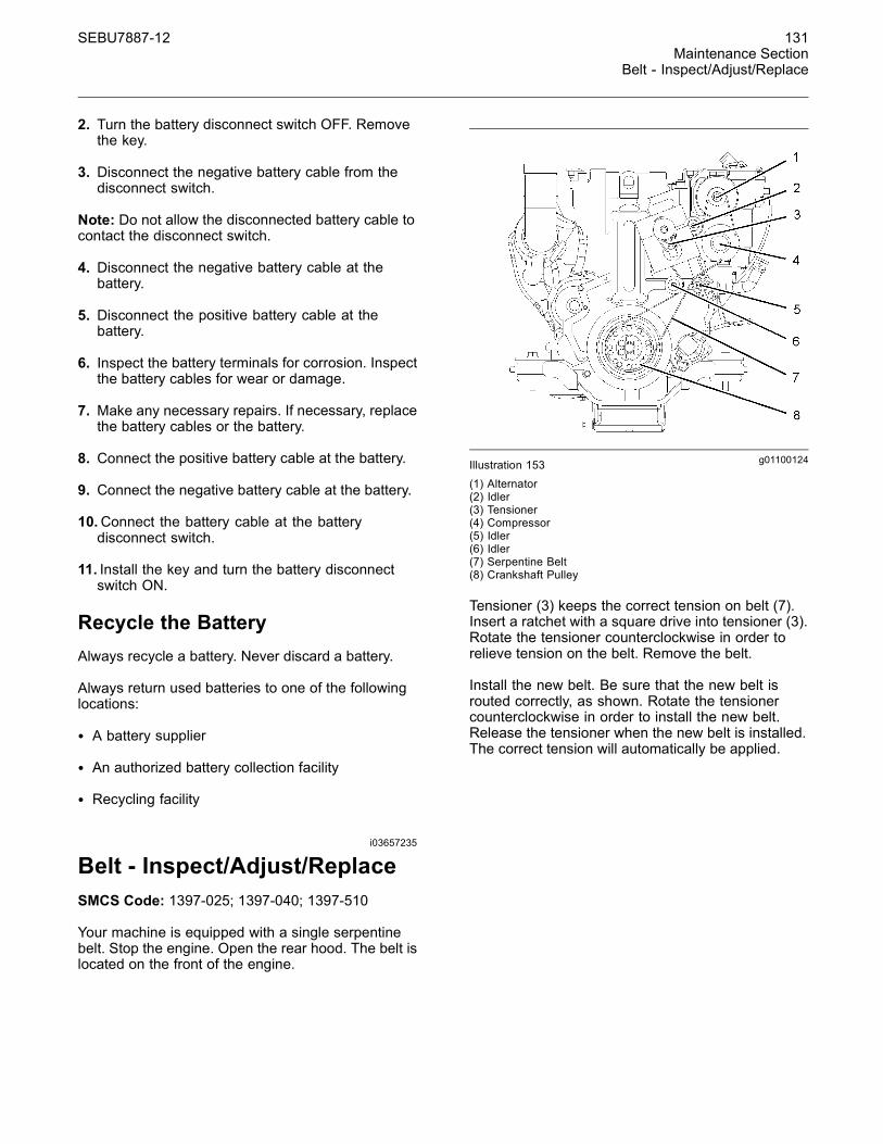
Belt - Inspect/Adjust/ReplaceSMCS Code: 1397-025; 1397-040; 1397-510
Your machine is equipped with a single serpentinebelt. Stop the engine. Open the rear hood. The belt islocated on the front of the engine.
g01100124Illustration 153(1) Alternator(2) Idler(3) Tensioner(4) Compressor(5) Idler(6) Idler(7) Serpentine Belt(8) Crankshaft Pulley
Tensioner (3) keeps the correct tension on belt (7).Insert a ratchet with a square drive into tensioner (3).Rotate the tensioner counterclockwise in order torelieve tension on the belt. Remove the belt.
Install the new belt. Be sure that the new belt isrouted correctly, as shown. Rotate the tensionercounterclockwise in order to install the new belt.Release the tensioner when the new belt is installed.The correct tension will automatically be applied.

132 SEBU7887-12Maintenance SectionBrake Accumulator - Check
i01714079
Brake Accumulator - CheckSMCS Code: 4263-535
g00882020Illustration 154
1. Turn the engine start switch to the ON position.The alert indicator for brake oil pressure shouldcome on if the braking system is not at normaloperating pressure.
2. Start the engine. Run the engine at half speed fortwo minutes in order to increase the accumulatorpressure. The alert indicator for brake oil pressureshould go off.
3. Stop the engine. Apply the service brake pedaland release the service brake pedal until the alertindicator for brake oil pressure comes on. This willdecrease the accumulator pressure. A minimumof five applications of the service brake pedal arerequired.
4. If the alert indicator comes on after less thanfive applications of the brake, measure theaccumulator precharge pressure. An authorizedCaterpillar dealer can measure the nitrogen gaspressure in the accumulator. Use only dry nitrogengas for recharging.
i01739721
Braking System - TestSMCS Code: 4251-081; 4267-081
• Fasten the seat belt before you test the brakes.
• Park the machine on a dry, level surface.
• Check the area around the machine. Make surethat the machine is clear of personnel and clear ofobstacles.
• Make sure that the steering frame lock is in theunlocked position.
The following tests are used to determine whetherthe braking system is functional. These tests are notintended to measure the maximum brake holdingeffort. The required brake holding effort for sustaininga machine at a specific engine rpm varies from onemachine to another machine. The variations includedifferences in the engine setting, the power trainefficiency, the brake holding ability, etc.
Service Brake Holding Ability Test
Personal injury can result if the machine moveswhile testing.
If the machine begins to move during test, reducethe engine speed immediately and engage theparking brake.
1. Start the engine. Raise the implement slightly.Apply the service brake. Release the parkingbrake.
2. Move the transmission control to THIRD SPEEDFORWARD while the service brakes are applied.Make sure that the autoshift control is in the OFFposition.
3. Gradually increase the engine speed to high idle.The machine should not move.
4. Reduce the engine speed to low idle. Move thetransmission direction control to the NEUTRALposition. Engage the parking brake. Lower theimplement to the ground. Stop the engine.
If the machine moved during the test, consult yourCaterpillar dealer for a brake inspection. Make anynecessary repairs before the machine is returned tooperation.
Parking Brake Holding Ability Test
Personal injury can result if the machine moveswhile testing.
If the machine begins to move, reduce the enginespeed immediately and apply the service brakepedal.
This test is performed when the parking brake isengaged. If the machine begins to move, comparethe engine rpm to the engine rpm of a prior test. Thiswill indicate the amount of system deterioration.

SEBU7887-12 133Maintenance Section
Bucket Cutting Edges - Inspect/Replace
1. Start the engine. Raise the implement slightly.Engage the parking brake.
2. Move the transmission control to THIRD SPEEDFORWARD. Make sure that the autoshift controlis in the OFF position.
The parking brake indicator light should come on.
3. Gradually increase the engine speed to high idle.The machine should not move.
4. Reduce the engine speed to low idle. Move thetransmission direction control to the NEUTRALposition. Lower the implement to the ground. Stopthe engine.
If the machine moved during the test, consult yourCaterpillar dealer for a brake inspection. Make anynecessary repairs before the machine is returned tooperation.
i03657238
Bucket Cutting Edges -Inspect/ReplaceSMCS Code: 6801-040; 6801-510
Personal injury or death can result from bucketfalling.
Block the bucket before changing bucket cuttingedges.
g00764365Illustration 155(1) Bolts for Cutting Edge(2) Cutting Edge
Check the cutting edges and the end bits for wearand for damage. Use the following procedure toservice the cutting edges and the end bits:
1. Raise the bucket and place blocking under thebucket.
2. Lower the bucket onto the blocking. Stop theengine.
3. Remove bolts (1), cutting edge (2) and the endbits.
4. Clean all contact surfaces.
5. If the opposite side of the cutting edge is not worn,use the opposite side of the cutting edge. The endbits are not reversible.
If both sides are worn, install a new cutting edge.
6. Install bolts (1). Tighten the bolts to the specifiedtorque.
Reference: Refer to Specifications, SENR3130,“Ground Engaging Tool (G.E.T.) Fasteners”.
7. Start the engine. Raise the bucket and remove theblocking. Lower the bucket to the ground.
8. After a few hours of operation, check the bolts forproper torque.
Bucket Wear Plates
Personal injury or death can result from the bucketfalling.
Block the bucket before changing bucket wearplates.
g00879740Illustration 156
Inspect the wear plates. Replace the wear platesbefore damage to the bottom of the bucket occurs.Consult your Caterpillar dealer for replacement ofwear plates.

134 SEBU7887-12Maintenance SectionBucket Hinge and Lift Arm Clearance Shims - Inspect/Adjust/Replace
i02895805
Bucket Hinge and LiftArm Clearance Shims -Inspect/Adjust/ReplaceSMCS Code: 6001-025-CLR; 6001-040-CLR;6001-510-Z4; 6119-025-CLR; 6119-040-CLR;6119-510-Z4
Inspect the Linkage
g01345690Illustration 157(1) Lift Arm(2) Bucket(3) Inspection Points for the Bucket Hinge.
Periodically inspect the bucket linkage. The gapbetween the bucket and the linkage should notexceed the thinnest shim that is available for thebucket assembly.
1. Lower the lift arm assembly (1) to suitableblocking. Rest the bucket (2) on the ground.
2. Use a gauge to measure the gap at the hinge.
3. If the measurement exceeds the required amount,new shims must be installed.
Installing Shims for the Hinge onthe BucketNote: Refer to the Disassembly and AssemblyManual, “Bucket - Remove” for the correct procedurefor removing the pins in the linkage.
g01345720Illustration 158(2) Bucket(4) Install washers on lift arm.
g01345724Illustration 159
(2) Bucket(4) Install washers on tilt arm.
Install washers and pin assembly to the bucket.When possible, use washers on both sides of the liftarm in order to reduce the gap between the lift armand the hinges on the bucket.
Note: Refer to the Disassembly and AssemblyManual, “Bucket - Install” for the correct procedurefor installing the pins in the linkage.

SEBU7887-12 135Maintenance Section
Bucket Linkage and Loader Cylinder Bearings - Lubricate
i03657090
Bucket Linkage and LoaderCylinder Bearings - LubricateSMCS Code: 5102-086-BD; 5104-086-BD;6107-086-BD
Crushing Hazard. Connect the steering frame lockbetween front and rear frames before servicing themachine in the articulation area. Disconnect thesteering frame lock and secure it in the stored po-sition before resuming operation. Failure to do socould result in serious injury or death.
Refer to Operation and Maintenance Manual,“Steering Frame Lock” before entering the articulationjoint.
Wipe off the fittings before any lubricant is applied.
g01001072Illustration 160
g01259751Illustration 161
To lubricate pins (1) and (3), apply grease throughthe remote fittings that are located on the right side ofthe machine near the articulation joint.
The pins (2), (4), (5), (6), and (7) do not have remotegrease fittings. These pins have standard greasefittings.
i01924084
Bucket Lower Pivot Bearings- LubricateSMCS Code: 6101-086-BD; 6107-086-BD
g01001411Illustration 162
Wipe off all fittings before any lubricant is applied.
Apply lubricant through one fitting on each side ofthe machine.
i03657242
Bucket Tips - Inspect/ReplaceSMCS Code: 6805-040; 6805-510
Personal injury or death can result from the bucketfalling.
Block the bucket before changing bucket tips.

136 SEBU7887-12Maintenance SectionBucket Tips - Inspect/Replace
Bucket Tips
g00101352Illustration 163
(1) Usable(2) Replace the tip.(3) Replace the tip.
Check the bucket tips for wear. If the bucket tip has ahole, replace the bucket tip.
1. Remove the pin from the bucket tip. The pin canbe removed by one of the following methods.
• Use a hammer and a punch from the retainerside of the bucket to drive out the pin.
• Use a Pin-Master. Follow Step 1.a through Step1.c for the procedure.
g00590670Illustration 164
(4) Back of Pin-Master(5) Extractor
a. Place the Pin-Master on the bucket tooth.
b. Align extractor (5) with the pin.
c. Strike the Pin-Master at the back of the tool (4)and remove the pin.
g00590819Illustration 165(6) Retainer(7) Retaining washer(8) Adapter
2. Clean the adapter and the pin.
3. Fit retainer (6) into retaining washer (7). Installthis assembly into the groove that is in the sideof adapter (8).
g00101359Illustration 166
4. Install the new bucket tip onto the adapter.
Note: The bucket tip can be rotated by 180 degrees inorder to allow greater penetration or less penetration.
5. Drive the pin through the bucket tip. The pin canbe installed by using one of the following methods:
• From the other side of the retainer, drive thepin through the bucket tip, the adapter, and theretainer.
• Use a Pin-Master. Follow Step 5.a through Step5.e for the procedure.
Note: To correctly install the pin into the retainer, thepin must be driven in from the right side of the tooth.Improper installation of the pin can result in the lossof the bucket tip.
SEBU7887-12 137Maintenance Section
Bucket Tips - Inspect/Replace
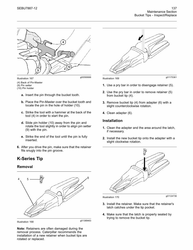
g00590666Illustration 167(4) Back of Pin-Master(9) Pin setter(10) Pin holder
a. Insert the pin through the bucket tooth.
b. Place the Pin-Master over the bucket tooth andlocate the pin in the hole of holder (10).
c. Strike the tool with a hammer at the back of thetool (4) in order to start the pin.
d. Slide pin holder (10) away from the pin androtate the tool slightly in order to align pin setter(9) with the pin.
e. Strike the end of the tool until the pin is fullyinserted.
6. After you drive the pin, make sure that the retainerfits snugly into the pin groove.
K-Series Tip
Removal
g01389463Illustration 168
Note: Retainers are often damaged during theremoval process. Caterpillar recommends theinstallation of a new retainer when bucket tips arerotated or replaced.
g01175361Illustration 169
1. Use a pry bar in order to disengage retainer (5).
2. Use the pry bar in order to remove retainer (5)from bucket tip (4).
3. Remove bucket tip (4) from adapter (6) with aslight counterclockwise rotation.
4. Clean adapter (6).
Installation
1. Clean the adapter and the area around the latch,if necessary.
2. Install the new bucket tip onto the adapter with aslight clockwise rotation.
g01124736Illustration 170
3. Install the retainer. Make sure that the retainer'slatch catches under the tip pocket.
4. Make sure that the latch is properly seated bytrying to remove the bucket tip.

138 SEBU7887-12Maintenance SectionBucket Upper Pivot Bearings - Lubricate
i01924086
Bucket Upper Pivot Bearings- LubricateSMCS Code: 6101-086-BD; 6107-086-BD
g01001416Illustration 171
Wipe off the fitting before any lubricant is applied.
Apply lubricant through the fitting.
i01449996
Cab Air Filter - Clean/ReplaceSMCS Code: 7342-070; 7342-510
Note: Clean the cab air filters more often if themachine is being operated in dusty conditions.
g00759048Illustration 172
1. Remove the filter cover behind the seat. Twothreaded knobs (1) are used in order to removethe cover. Remove the filter element (2).
2. Open the access door (3) on the left side of thecab. Remove the filter element.
3. Clean the filter elements with pressure air orwash the filter elements in warm water with anonsudsing household detergent.
4. If water and detergent are used to clean the filterelements, rinse the filter elements in clean waterand allow the filter elements to air dry thoroughly.
Note: If either filter element is damaged, install anew filter element.
5. Install the filter elements. Install the filter coverand close the access door.
i02816405
Camera - Clean(If Equipped)SMCS Code: 7348-070
In order to maintain sufficient vision, keep the WorkArea Vision System (WAVS) camera lens and thedisplay clean.
Display
g01223034Illustration 173
WAVS display
Use a soft, damp cloth in order to clean the display.The display has a soft plastic surface that can beeasily damaged by an abrasive material. The displayis not sealed. Do not immerse the display withliquid.
SEBU7887-12 139Maintenance Section
Circuit Breakers - Reset
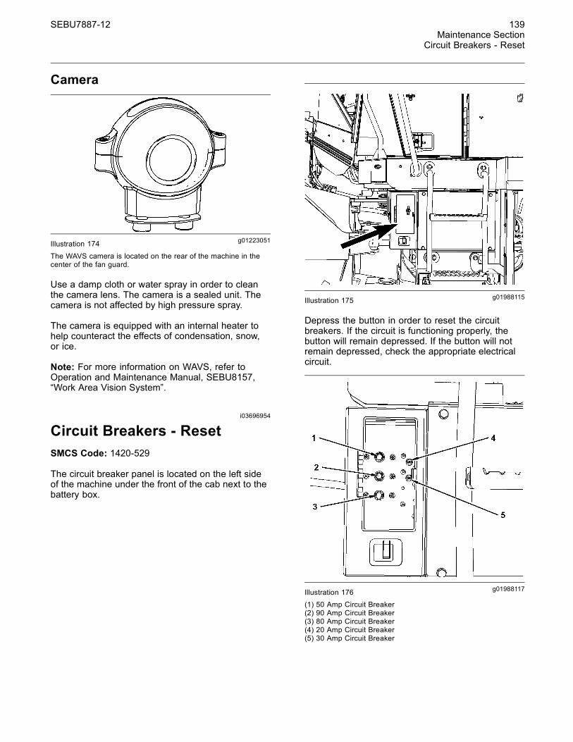
Camera
g01223051Illustration 174
The WAVS camera is located on the rear of the machine in thecenter of the fan guard.
Use a damp cloth or water spray in order to cleanthe camera lens. The camera is a sealed unit. Thecamera is not affected by high pressure spray.
The camera is equipped with an internal heater tohelp counteract the effects of condensation, snow,or ice.
Note: For more information on WAVS, refer toOperation and Maintenance Manual, SEBU8157,“Work Area Vision System”.
i03696954
Circuit Breakers - ResetSMCS Code: 1420-529
The circuit breaker panel is located on the left sideof the machine under the front of the cab next to thebattery box.
g01988115Illustration 175
Depress the button in order to reset the circuitbreakers. If the circuit is functioning properly, thebutton will remain depressed. If the button will notremain depressed, check the appropriate electricalcircuit.
g01988117Illustration 176(1) 50 Amp Circuit Breaker(2) 90 Amp Circuit Breaker(3) 80 Amp Circuit Breaker(4) 20 Amp Circuit Breaker(5) 30 Amp Circuit Breaker

140 SEBU7887-12Maintenance SectionCooling System Coolant (ELC) - Change
i01921776
Cooling System Coolant (ELC)- ChangeSMCS Code: 1350-044-NL
Pressurized system: Hot coolant can cause seri-ous burn. To open cap, stop engine, wait until ra-diator is cool. Then loosen cap slowly to relievethe pressure.
NOTICECare must be taken to ensure that fluids are containedduring performance of inspection, maintenance, test-ing, adjusting and repair of the product. Be prepared tocollect the fluid with suitable containers before open-ing any compartment or disassembling any compo-nent containing fluids.
Refer to Special Publication, NENG2500, “CaterpillarTools and Shop Products Guide” for tools and suppliessuitable to collect and contain fluids on Caterpillarproducts.
Dispose of all fluids according to local regulations andmandates.
Reference: For information about adding Extenderto your cooling system, refer to Operation andMaintenance Manual, “Cooling System CoolantExtender (ELC) - Add” or consult your Caterpillardealer.
If an Extended Life Coolant was previously used,flush the cooling system with clean water. No othercleaning agents are required. Use the followingprocedure to change the Extended Life Coolant.
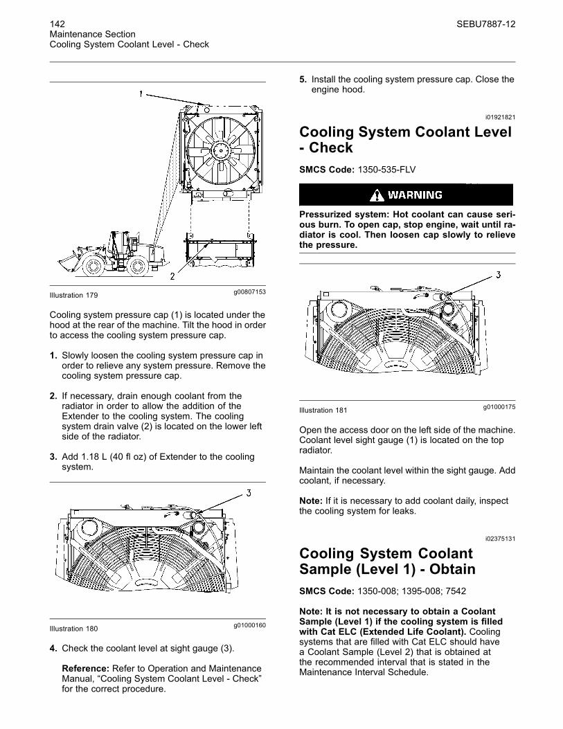
g00807153Illustration 177
The cooling system pressure cap (1) is located underthe engine hood at the rear of the machine.
1. Slowly loosen the cooling system pressure cap inorder to relieve any system pressure.
2. Open the access door on the left side of themachine in order to access coolant drain valve (2).Open the drain valve at the bottom of the radiator.Allow the coolant to drain into a suitable container.
3. Flush the cooling system with clean water until thedraining water is clean. Close drain valve (2).
4. Replace the water temperature regulator.
Reference: Refer to Operation and MaintenanceManual, “Cooling System Water TemperatureRegulator - Replace” for the correct procedure.
NOTICETopping off or mixing Cat ELC with other products thatdo not meet Caterpillar EC-1 specifications reducesthe effectiveness of the coolant and shortens coolantservice life.
Use only Caterpillar products or commercial productsthat have passed the Caterpillar EC-1 specification forpre-mixed or concentrate coolants. Use only Extenderwith Cat ELC.
Failure to follow these recommendations can result inshortened cooling system component life.
5. Add the Extended Life Coolant.

SEBU7887-12 141Maintenance Section
Cooling System Coolant Extender (ELC) - Add
Reference: Refer to Operation and MaintenanceManual, “Capacities (Refill)” for the capacity of thecooling system.
6. Start the engine. Run the engine without thecooling system pressure cap until the watertemperature regulator opens and the coolant levelstabilizes.
g01000160Illustration 178
7. Maintain the coolant level in sight gauge (3) onthe upper radiator.
8. Install the cooling system pressure cap. Stop theengine.
i01921794
Cooling System CoolantExtender (ELC) - AddSMCS Code: 1352-544-NL
Pressurized system: Hot coolant can cause seri-ous burn. To open cap, stop engine, wait until ra-diator is cool. Then loosen cap slowly to relievethe pressure.
NOTICECare must be taken to ensure that fluids are containedduring performance of inspection, maintenance, test-ing, adjusting and repair of the product. Be prepared tocollect the fluid with suitable containers before open-ing any compartment or disassembling any compo-nent containing fluids.
Refer to Special Publication, NENG2500, “CaterpillarTools and Shop Products Guide” for tools and suppliessuitable to collect and contain fluids on Caterpillarproducts.
Dispose of all fluids according to local regulations andmandates.
NOTICETopping off or mixing Cat ELC with other products thatdo not meet Caterpillar EC-1 specifications reducesthe effectiveness of the coolant and shortens coolantservice life.
Use only Caterpillar products or commercial productsthat have passed the Caterpillar EC-1 specification forpre-mixed or concentrate coolants. Use only Extenderwith Cat ELC.
Failure to follow these recommendations can result inshortened cooling system component life.
When a Caterpillar Extended Life Coolant (ELC) isused, an Extender must be added to the coolingsystem.
Use a 8T-5296 Coolant Test Kit to check theconcentration of the coolant.
Reference: For additional information aboutthe addition of Extender, refer to SpecialPublication, SEBU6250, “Caterpillar Machine FluidsRecommendations” or consult your Caterpillar dealer.
142 SEBU7887-12Maintenance SectionCooling System Coolant Level - Check
g00807153Illustration 179
Cooling system pressure cap (1) is located under thehood at the rear of the machine. Tilt the hood in orderto access the cooling system pressure cap.
1. Slowly loosen the cooling system pressure cap inorder to relieve any system pressure. Remove thecooling system pressure cap.
2. If necessary, drain enough coolant from theradiator in order to allow the addition of theExtender to the cooling system. The coolingsystem drain valve (2) is located on the lower leftside of the radiator.
3. Add 1.18 L (40 fl oz) of Extender to the coolingsystem.
g01000160Illustration 180
4. Check the coolant level at sight gauge (3).
Reference: Refer to Operation and MaintenanceManual, “Cooling System Coolant Level - Check”for the correct procedure.
5. Install the cooling system pressure cap. Close theengine hood.
i01921821
Cooling System Coolant Level- CheckSMCS Code: 1350-535-FLV
Pressurized system: Hot coolant can cause seri-ous burn. To open cap, stop engine, wait until ra-diator is cool. Then loosen cap slowly to relievethe pressure.
g01000175Illustration 181
Open the access door on the left side of the machine.Coolant level sight gauge (1) is located on the topradiator.
Maintain the coolant level within the sight gauge. Addcoolant, if necessary.
Note: If it is necessary to add coolant daily, inspectthe cooling system for leaks.
i02375131
Cooling System CoolantSample (Level 1) - ObtainSMCS Code: 1350-008; 1395-008; 7542
Note: It is not necessary to obtain a CoolantSample (Level 1) if the cooling system is filledwith Cat ELC (Extended Life Coolant). Coolingsystems that are filled with Cat ELC should havea Coolant Sample (Level 2) that is obtained atthe recommended interval that is stated in theMaintenance Interval Schedule.

SEBU7887-12 143Maintenance Section
Cooling System Coolant Sample (Level 2) - Obtain
Note: Obtain a Coolant Sample (Level 1) if thecooling system is filled with any other coolantinstead of Cat ELC. This includes the followingtypes of coolants.
• Commercial long life coolants that meet theCaterpillar Engine Coolant Specification -1(Caterpillar “EC−1”)
• Cat Diesel Engine Antifreeze/Coolant (DEAC)
• Commercial heavy-duty coolant/antifreeze
NOTICEAlways use a designated pump for oil sampling, anduse a separate designated pump for coolant sampling.Using the same pump for both types of samples maycontaminate the samples that are being drawn. Thiscontaminate may cause a false analysis and an incor-rect interpretation that could lead to concerns by bothdealers and customers.
Note: Level 1 results may indicate a need forLevel 2 Analysis.
g01185306Illustration 182Left side of machine
The sampling valve (1) for the cooling system islocated on top of the engine toward the front of theengine on the left side of the machine.
Obtain the sample of the coolant as close as possibleto the recommended sampling interval. In orderto receive the full effect of S·O·S analysis, youmust establish a consistent trend of data. In orderto establish a pertinent history of data, performconsistent samplings that are evenly spaced.Supplies for collecting samples can be obtained fromyour Caterpillar dealer.
Use the following guidelines for proper sampling ofthe coolant:
• Complete the information on the label for thesampling bottle before you begin to take thesamples.
• Keep the unused sampling bottles stored in plasticbags.
• Obtain coolant samples directly from the coolantsample port. You should not obtain the samplesfrom any other location.
• Keep the lids on empty sampling bottles until youare ready to collect the sample.
• Place the sample in the mailing tube immediatelyafter obtaining the sample in order to avoidcontamination.
• Never collect samples from expansion bottles.
• Never collect samples from the drain for a system.
Submit the sample for Level 1 analysis.
For additional information about coolant analysis, seeSpecial Publication, SEBU6250, “Caterpillar MachineFluids Recommendations” or consult your Caterpillardealer.
i02375133
Cooling System CoolantSample (Level 2) - ObtainSMCS Code: 1350-008; 1395-008; 7542
NOTICEAlways use a designated pump for oil sampling, anduse a separate designated pump for coolant sampling.Using the same pump for both types of samples maycontaminate the samples that are being drawn. Thiscontaminate may cause a false analysis and an incor-rect interpretation that could lead to concerns by bothdealers and customers.
g01185306Illustration 183Left side of the machine

144 SEBU7887-12Maintenance SectionCooling System Water Temperature Regulator - Replace
The sampling valve (1) for the cooling system islocated on top of the engine toward the front of theengine on the left side of the machine.
Obtain the sample of the coolant as close as possibleto the recommended sampling interval. Suppliesfor collecting samples can be obtained from yourCaterpillar dealer.
Refer to Operation and Maintenance Manual,“Cooling System Coolant Sample (Level 1) - Obtain”for the guidelines for proper sampling of the coolant.
Submit the sample for Level 2 analysis.
Reference: For additional information about coolantanalysis, refer to Special Publication, SEBU6250,“Caterpillar Machine Fluids Recommendations” orconsult your Caterpillar dealer.
i02186511
Cooling System WaterTemperature Regulator -ReplaceSMCS Code: 1355-510; 1393-010
Pressurized system: Hot coolant can cause seri-ous burn. To open cap, stop engine, wait until ra-diator is cool. Then loosen cap slowly to relievethe pressure.
NOTICEFailure to replace the engine's thermostat on a regu-larly scheduled basis could cause severe engine dam-age.
NOTICECaterpillar engines incorporate a shunt design coolingsystem and require operating the engine with a ther-mostat installed.
If the thermostat is installed wrong, it will cause theengine to overheat. Inspect gaskets before assemblyand replace if worn or damaged.
g01105775Illustration 184
Replace the water temperature regulator in orderto reduce the chance of problems with the coolingsystem.
Replace the water temperature regulator and theseals while the cooling system is completely drainedor while the coolant is drained to a level that is belowthe water temperature regulator housing.
Note: If you are only replacing the water temperatureregulator, drain the coolant to a level that is below thewater temperature regulator housing.
Reference: Refer to Disassembly and Assembly,RENR9214, “C11 and C13 Engines for CaterpillarBuilt Machines” for the correct procedure for replacingthe water temperature regulator.
SEBU7887-12 145Maintenance Section
Differential and Final Drive Oil - Change
i02164355
Differential and Final Drive Oil- ChangeSMCS Code: 3278-044; 4011-044
NOTICECare must be taken to ensure that fluids are containedduring performance of inspection, maintenance, test-ing, adjusting and repair of the product. Be prepared tocollect the fluid with suitable containers before open-ing any compartment or disassembling any compo-nent containing fluids.
Refer to Special Publication, NENG2500, “CaterpillarTools and Shop Products Guide” for tools and suppliessuitable to collect and contain fluids on Caterpillarproducts.
Dispose of all fluids according to local regulations andmandates.
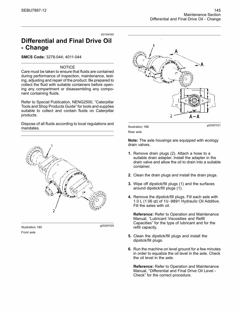
g00287529Illustration 185Front axle
g00287531Illustration 186Rear axle
Note: The axle housings are equipped with ecologydrain valves.
1. Remove drain plugs (2). Attach a hose to asuitable drain adapter. Install the adapter in thedrain valve and allow the oil to drain into a suitablecontainer.
2. Clean the drain plugs and install the drain plugs.
3. Wipe off dipstick/fill plugs (1) and the surfacesaround dipstick/fill plugs (1).
4. Remove the dipstick/fill plugs. Fill each axle with1.0 L (1.06 qt) of 1U-9891 Hydraulic Oil Additive.Fill the axles with oil.
Reference: Refer to Operation and MaintenanceManual, “Lubricant Viscosities and RefillCapacities” for the type of lubricant and for therefill capacity.
5. Clean the dipstick/fill plugs and install thedipstick/fill plugs.
6. Run the machine on level ground for a few minutesin order to equalize the oil level in the axle. Checkthe oil level in the axle.
Reference: Refer to Operation and MaintenanceManual, “Differential and Final Drive Oil Level -Check” for the correct procedure.

146 SEBU7887-12Maintenance SectionDifferential and Final Drive Oil Level - Check
i01102280
Differential and Final Drive OilLevel - CheckSMCS Code: 3278-535-FLV; 4011-535-FLV
Note: Before you measure the oil level, operate themachine for a few minutes in order to equalize theoil level.
1. Park the machine on level ground. Lower thebucket and apply slight downward pressure.Engage the parking brake. Stop the engine.
g00285312Illustration 187Front Axle
g00287527Illustration 188
Rear Axle
2. Remove dipstick/fill plug (1) on the left side of theaxle. Wipe off the level gauge with a clean clothand reinsert the plug. This will ensure a moreaccurate measurement of the oil level.
Note: Make sure that the plug is installed completelybefore you check the oil level. If the plug is notinstalled completely, an incorrect oil level reading canoccur.
3. Remove dipstick/fill plug (1) again and check theoil level. Maintain the oil level between the ADDmark and the FULL mark. Add oil, if necessary.
Reference: Refer to Operation and MaintenanceManual, “Lubricant Viscosities and RefillCapacities” for the type of lubricant and for therefill capacity.
4. Clean the plug and install the plug.
i01921974
Differential and Final Drive OilSample - ObtainSMCS Code: 3278-008; 4011-008; 4070-008; 7542
NOTICECare must be taken to ensure that fluids are containedduring performance of inspection, maintenance, test-ing, adjusting and repair of the product. Be prepared tocollect the fluid with suitable containers before open-ing any compartment or disassembling any compo-nent containing fluids.
Refer to Special Publication, NENG2500, “CaterpillarTools and Shop Products Guide” for tools and suppliessuitable to collect and contain fluids on Caterpillarproducts.
Dispose of all fluids according to local regulations andmandates.
1. Operate the machine for a few minutes beforeobtaining the oil sample. This will thoroughly mixthe differential oil for a more accurate sample.
SEBU7887-12 147Maintenance Section
Drive Shaft Spline (Center) - Lubricate
g00884056Illustration 189Rear axle
g00884059Illustration 190Front axle
2. The differential and final drives are not equippedwith sampling valves. Obtaining an oil sample willrequire the use of a vacuum pump or equivalentin order to extract the oil from the component.Extract the oil through the filler openings on thedifferential and final drives.
3. Complete any additional required work. Fill thedifferential and final drives with oil, as required.Install the dipstick/fill plugs.
Reference: For more information, refer to SpecialPublication, SEBU6250, “Caterpillar Machine FluidsRecommendations”, “S·O·S Oil Analysis” and SpecialPublication, PEHP6001, “How To Take A Good OilSample”.
i03657243
Drive Shaft Spline (Center) -LubricateSMCS Code: 3253-086-SN
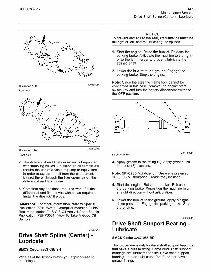
Wipe all of the fittings before you apply grease tothe fittings.
NOTICETo prevent damage to the seal, articulate the machinefull right or left, before lubricating the splines.
1. Start the engine. Raise the bucket. Release theparking brake. Articulate the machine to the rightor to the left in order to properly lubricate thesplined shaft.
2. Lower the bucket to the ground. Engage theparking brake. Stop the engine.
Note: Since the steering frame lock cannot beconnected in this case, remove the engine startswitch key and turn the battery disconnect switch tothe OFF position.
g01106848Illustration 191
3. Apply grease to the fitting (1). Apply grease untilthe relief (2) overruns.
Note: 5P-0960 Molybdenum Grease is preferred.1P-0808 Multipurpose Grease may be used.
4. Start the engine. Raise the bucket. Releasethe parking brake. Reposition the machine in astraight direction without articulation.
5. Lower the bucket to the ground. Apply a slightdown pressure. Engage the parking brake. Stopthe engine.
i03657245
Drive Shaft Support Bearing -LubricateSMCS Code: 3267-086-BD
This procedure is only for drive shaft support bearingsthat have a grease fitting. Some drive shaft supportbearings are lubricated for life. Drive shaft supportbearings that are lubricated for life do not havegrease fittings.

148 SEBU7887-12Maintenance SectionDrive Shaft Universal Joints - Lubricate
Note: For better access, articulate the machine tothe right or to the left. Because the steering framelock cannot be connected, remove the engine startswitch key and turn the battery disconnect switch tothe OFF position in order to keep the machine frombeing articulated.
In order to lubricate the drive shaft support bearing,you must remove the plug and you must inserta grease zerk. After you lubricate the drive shaftsupport bearing, remove the grease zerk and installthe plug. Do not grease the drive shaft supportbearing more than the recommended interval.
NOTICEDo not over grease the drive shaft support bearing.The excess grease may get into the brake area. Dam-age to the brakes or the loss of the brakes may occur.Take precautions in order to avoid getting grease inthe adjacent brake area.
g01962154Illustration 192
g00111696Illustration 193
Wipe off the fitting before any lubricant is applied.
Apply lubricant through the fitting on the drive shaftsupport bearing. Refer to Operation and MaintenanceManual, “Lubricant Viscosities” for the proper grease.
i02571972
Drive Shaft Universal Joints -LubricateSMCS Code: 3251-086
Note: Do not grease the universal joints morethan the recommended interval.
g01069141Illustration 194
1. Wipe off the grease fittings before lubricating.
2. Lubricate all five grease fittings on the universaljoints. Refer to Operation and MaintenanceManual, “Lubricant Viscosities” for the propergrease.
i02061807
Electronic Unit Injector -Inspect/AdjustSMCS Code: 1251-025; 1251-040; 1290-025;1290-040
The Electronic Control module produces highvoltage. To prevent personal injury make sure theElectronic Control Module is not powered and theunit injector solenoids are disconnected.
NOTICEThe camshafts must be correctly timed with the crank-shaft before an adjustment of the unit injector lashis made. The timing pins must be removed from thecamshafts before the crankshaft is turned or damageto the cylinder block will be the result.

SEBU7887-12 149Maintenance Section
Engine Air Filter Primary Element - Clean/Replace
The operation of Caterpillar engines with improperadjustments of the electronic unit injector can reduceengine efficiency. This reduced efficiency could resultin excessive fuel usage and/or shortened enginecomponent life.
Adjust the electronic unit injector at the same intervalas the valve lash adjustment.
Refer to your machine's Service Manual or yourCaterpillar dealer for the complete adjustmentprocedure.
i02187095
Engine Air Filter PrimaryElement - Clean/ReplaceSMCS Code: 1054-070-PY; 1054-510-PY
1. The rear hood should be opened in order toaccess the air filter. The air filter is located on theright side of the machine.
g01105972Illustration 195
2. Remove the cover on air filter housings (3).
3. Remove primary element (2) from the air filterhousing.
4. Clean the inside of air filter housing (1).
5. Inspect the primary element. If the pleats, thegaskets, or the seals are damaged, discard theelement. Replace a damaged primary elementwith a clean primary element.
Cleaning Primary Air FilterElements
NOTICECaterpillar recommends certified air filter cleaning ser-vices available at participating Caterpillar dealers. TheCaterpillar cleaning process uses proven proceduresto assure consistent quality and sufficient filter life.
Observe the following guidelines if you attempt toclean the filter element:
Do not tap or strike the filter element in order to re-move dust.
Do not wash the filter element.
Use low pressure compressed air in order to removethe dust from the filter element. Air pressure must notexceed 207 kPa (30 psi). Direct the air flow up thepleats and down the pleats from the inside of the filterelement. Take extreme care in order to avoid damageto the pleats.
Do not use air filters with damaged pleats, gaskets, orseals. Dirt entering the engine will cause damage toengine components.
The primary air filter element can be used up tosix times if the element is properly cleaned and theelement is inspected. When the primary air filterelement is cleaned, check for rips or tears in the filtermaterial. The primary air filter element should bereplaced at least one time per year. This replacementshould be performed regardless of the number ofcleanings.
NOTICEDo not clean the air filter elements by bumping or tap-ping. This could damage the seals. Do not use ele-ments with damaged pleats, gaskets, or seals. Dam-aged elements will allow dirt to pass through. Enginedamage could result.
Visually inspect the primary air filter elements beforecleaning. Inspect the air filter elements for damageto the seal, the gaskets, and the outer cover. Discardany damaged air filter elements.
There are two common methods that are used toclean primary air filter elements:
• Pressurized air
• Vacuum cleaning

150 SEBU7887-12Maintenance SectionEngine Air Filter Primary Element - Clean/Replace
Pressurized Air
Pressurized air can be used to clean primary air filterelements that have not been cleaned more than twotimes. Pressurized air will not remove deposits ofcarbon and oil. Use filtered, dry air with a maximumpressure of 207 kPa (30 psi).
g00281692Illustration 196
Note: When the primary air filter elements arecleaned, always begin with the clean side (inside)in order to force dirt particles toward the dirty side(outside).
Aim the hose so that the air flows inside the elementalong the length of the filter in order to help preventdamage to the paper pleats. Do not aim the stream ofair directly at the primary air filter element. Dirt couldbe forced further into the pleats.
Vacuum Cleaning
Vacuum cleaning is another method for cleaningprimary air filter elements which require daily cleaningbecause of a dry, dusty environment. Cleaning withpressurized air is recommended prior to vacuumcleaning. Vacuum cleaning will not remove depositsof carbon and oil.
Inspecting the Primary Air FilterElements
g00281693Illustration 197
Inspect the clean, dry primary air filter element. Usea 60 watt blue light in a dark room or in a similarfacility. Place the blue light in the primary air filterelement. Rotate the primary air filter element. Inspectthe primary air filter element for tears and/or holes.Inspect the primary air filter element for light that mayshow through the filter material. If it is necessary inorder to confirm the result, compare the primary airfilter element to a new primary air filter element thathas the same part number.
Do not use a primary air filter element that has anytears and/or holes in the filter material. Do not usea primary air filter element with damaged pleats,gaskets or seals. Discard damaged primary air filterelements.
Storing Primary Air Filter Elements
If a primary air filter element that passes inspectionwill not be used, the primary air filter element canbe stored for future use.
g00281694Illustration 198
SEBU7887-12 151Maintenance Section
Engine Air Filter Secondary Element - Replace
Do not use paint, a waterproof cover, or plastic as aprotective covering for storage. An airflow restrictionmay result. To protect against dirt and damage, wrapthe primary air filter elements in Volatile CorrosionInhibited (VCI) paper.
Place the primary air filter element into a box forstorage. For identification, mark the outside of thebox and mark the primary air filter element. Includethe following information:
• Date of cleaning
• Number of cleanings
Store the box in a dry location.
i01693619
Engine Air Filter SecondaryElement - ReplaceSMCS Code: 1054-510-SE
NOTICEService the air filter only with the engine stopped. En-gine damage could result.
NOTICEAlways replace the secondary element. Do not at-tempt to reuse it by cleaning. Engine damage couldresult.
Note: Replace the secondary element when youservice the primary element for the third time. Ifa clean primary element has been installed anda warning for the air filter still occurs, replace thesecondary element. Also if the exhaust smokeremains black and a clean primary element has beeninstalled, replace the secondary element.
1. Remove the primary element.
Reference: Refer to Operation and MaintenanceManual, “Engine Air Filter Primary Element -Clean/Replace” for the correct procedure.
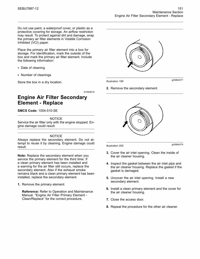
g00864077Illustration 199
2. Remove the secondary element.
g00864079Illustration 200
3. Cover the air inlet opening. Clean the inside ofthe air cleaner housing.
4. Inspect the gasket between the air inlet pipe andthe air cleaner housing. Replace the gasket if thegasket is damaged.
5. Uncover the air inlet opening. Install a newsecondary element.
6. Install a clean primary element and the cover forthe air cleaner housing.
7. Close the access door.
8. Repeat the procedure for the other air cleaner.

152 SEBU7887-12Maintenance SectionEngine Crankcase Breather - Clean
i02197033
Engine Crankcase Breather -CleanSMCS Code: 1317-070
g01109682Illustration 201
Open the hood on the rear of machine in order toaccess the engine compartment. The crankcasebreather is located on the right side of the engine.
1. Remove the four bolts (1) that hold the breather(2) onto the cover. Remove the breather.
2. Check the condition of the cover seal (3). Replacethe seal if the seal is damaged.
3. Wash the breather (2) and the filter element in aclean nonflammable solvent. The filter element islocated inside the breather.
4. Shake the breather or use pressure air in orderto dry the breather.
5. Inspect the breather hose for damage. Replacethe breather hose if it is necessary.
6. Install the breather assembly. Install the hose andinstall the hose clamp.
7. Close the access door.
i03650001
Engine Oil (High Speed) andOil Filter - Change(If Equipped)SMCS Code: 1318-510-HZ
Selection of the Oil Change Interval
NOTICEA 500 hour engine oil change interval is available, pro-vided that the operating conditions and recommend-ed multigrade oil types are met. When these require-ments are not met, shorten the oil change intervalto 250 hours, or use an S·O·S Services oil samplingand analysis program to determine an acceptable oilchange interval.
If you select an interval for oil and filter change that istoo long, you may damage the engine.
The normal engine oil change interval is listed in thisOperation and Maintenance Manual, “MaintenanceInterval Schedule”.
Abnormally harsh operating cycles or harshenvironments can shorten the service life ofthe engine oil. Arctic temperatures, corrosiveenvironments, or extremely dusty conditions mayrequire a reduction in engine oil change intervals.Also refer to Special Publication, SEBU5898, “ColdWeather Recommendations for All CaterpillarMachines”. Poor maintenance of air filters or of fuelfilters requires reduced oil change intervals. Consultyour Caterpillar dealer for more information if thisproduct will experience abnormally harsh operatingcycles or harsh environments.
Adjustment of the Oil Change Interval
Note: Your Caterpillar dealer has additionalinformation on these programs.
Cat oil filters are recommended.
Program A
Verification for an Oil Change Interval of 500 Hours
This program consists of three oil change intervals of500 hours. Oil sampling and analysis is done at 250hours and 500 hours for each of the three intervalsfor a total of six oil samples. The analysis includesoil viscosity and infrared (IR) analysis of the oil. Ifall of the results are satisfactory, the 500 hour oilchange interval is acceptable for the machine in thatapplication. Repeat Program A if you change theapplication of the machine.
SEBU7887-12 153Maintenance Section
Engine Oil (High Speed) and Oil Filter - Change
If a sample does not pass the oil analysis, take oneof these actions:
• Shorten the oil change interval to 250 hours.
• Proceed to Program B.
• Change to a preferred oil type in the “LubricantViscosities for Ambient Temperatures” Table in thisOperation and Maintenance Manual
Program B
Optimizing Oil Change Intervals
Begin with a 250 hour oil change interval. The oilchange intervals are adjusted by increments. Eachincrement is an additional 50 hours. Periodic oilsampling and analysis is done during each interval.The analysis includes oil viscosity and infrared (IR)analysis of the oil. Repeat Program B if you changethe application of the machine.
If an oil sample does not pass the analysis, shortenthe oil change interval, or change to a preferredmultigrade oil type in the listing above.
References
Reference: Special Publication, SEBU6250,“Caterpillar Machine Fluids Recommendations”
Reference: Special Publication, SEBU5898, “ColdWeather Recommendations for All CaterpillarMachines”
Reference: Special Publication, PEDP7035,“Optimizing Oil Change Intervals”
Reference: Special Publication, PEDP7036, “S·O·SFluid Analysis”
Reference: Special Publication, PEDP7076,“Understanding the S·O·S Oil Analysis Tests”
Procedure for Changing the EngineOil and Filter
NOTICECare must be taken to ensure that fluids are containedduring performance of inspection, maintenance, test-ing, adjusting and repair of the product. Be prepared tocollect the fluid with suitable containers before open-ing any compartment or disassembling any compo-nent containing fluids.
Refer to Special Publication, NENG2500, “CaterpillarDealer Service Tool Catalog” for tools and suppliessuitable to collect and contain fluids on Caterpillarproducts.
Dispose of all fluids according to local regulations andmandates.
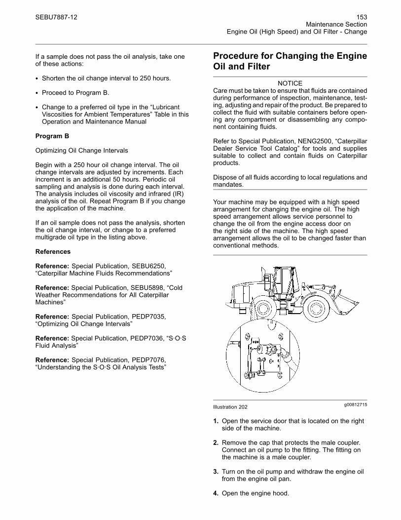
Your machine may be equipped with a high speedarrangement for changing the engine oil. The highspeed arrangement allows service personnel tochange the oil from the engine access door onthe right side of the machine. The high speedarrangement allows the oil to be changed faster thanconventional methods.
g00812715Illustration 202
1. Open the service door that is located on the rightside of the machine.
2. Remove the cap that protects the male coupler.Connect an oil pump to the fitting. The fitting onthe machine is a male coupler.
3. Turn on the oil pump and withdraw the engine oilfrom the engine oil pan.
4. Open the engine hood.

154 SEBU7887-12Maintenance SectionEngine Oil (High Speed) and Oil Filter - Change
g01109909Illustration 203
5. Use a strap type wrench to remove the filterelement. Inspect the filter.
6. Clean the filter mounting base with a clean cloth.Make sure that the used filter gasket has beencompletely removed.
g00101318Illustration 204
7. Apply a thin film of clean engine oil to the sealon the new filter element. Install a new engine oilfilter hand tight until the seal of the engine oil filtercontacts the base. Note the position of the indexmarks on the filter in relation to a fixed point onthe filter base.
Note: There are rotation index marks on the engineoil filter that are spaced 90 degrees or 1/4 or a turnaway from each other. When you tighten the engineoil filter, use the rotation index marks as a guide.
8. Tighten the filter according to the instructionsthat are printed on the filter. Use the index marksas a guide. For non-Caterpillar filters, use theinstructions that are provided with the filter.
Note: You may need to use a Caterpillar strapwrench, or another suitable tool, in order to turnthe filter to the amount that is required for finalinstallation. Make sure that the installation tool doesnot damage the filter.
9. Connect an oil pump to the male coupler for thehigh speed arrangement. Fill the crankcase withnew oil.
Reference: Refer to Operation and MaintenanceManual, “Lubricant Viscosities and RefillCapacities” for the correct type of oil and for thecorrect amount of oil.
10.Clean the end of the male coupler. Clean the capthat covers the male coupler and install the cap.
11.Start the engine and allow the oil to warm. Checkthe machine for oil leaks.
12.Check the engine oil level.
Reference: Refer to Operation and MaintenanceManual, “Engine Oil Level - Check” for the correctprocedure.
13.Stop the engine. Close the engine access doorand the engine hood.

SEBU7887-12 155Maintenance Section
Engine Oil Level - Check
i02188149
Engine Oil Level - CheckSMCS Code: 1000-535-FLV
g01106343Illustration 205
Open the service door that is located on the rightside of the machine. The oil level dipstick is locatedin the service door.
g00746755Illustration 206
Maintain the oil level between the FULL mark andADD mark on the dipstick. Check the level of theengine oil while the engine is shut off. Add oil, ifnecessary.
i02188187
Engine Oil Sample - ObtainSMCS Code: 1348-008; 7542
NOTICECare must be taken to ensure that fluids are containedduring performance of inspection, maintenance, test-ing, adjusting and repair of the product. Be prepared tocollect the fluid with suitable containers before open-ing any compartment or disassembling any compo-nent containing fluids.
Refer to Special Publication, NENG2500, “CaterpillarTools and Shop Products Guide” for tools and suppliessuitable to collect and contain fluids on Caterpillarproducts.
Dispose of all fluids according to local regulations andmandates.
1. Operate the machine for a few minutes beforeobtaining the oil sample. This will thoroughly mixthe engine oil for a more accurate sample.
2. Open the engine hood.
g01106355Illustration 207
3. Use the sampling valve in order to obtain asample of engine oil.
4. Close the engine hood.
Reference: For more information, refer to SpecialPublication, SEBU6250, “Caterpillar Machine FluidsRecommendations”, “S·O·S Oil Analysis” and SpecialPublication, PEHP6001, “How To Take A Good OilSample”.

156 SEBU7887-12Maintenance SectionEngine Oil and Filter - Change
i03649999
Engine Oil and Filter - ChangeSMCS Code: 1318-510
Selection of the Oil Change Interval
NOTICEA 500 hour engine oil change interval is available, pro-vided that the operating conditions and recommend-ed multigrade oil types are met. When these require-ments are not met, shorten the oil change intervalto 250 hours, or use an S·O·S Services oil samplingand analysis program to determine an acceptable oilchange interval.
If you select an interval for oil and filter change that istoo long, you may damage the engine.
The normal engine oil change interval is listed in thisOperation and Maintenance Manual, “MaintenanceInterval Schedule”.
Abnormally harsh operating cycles or harshenvironments can shorten the service life ofthe engine oil. Arctic temperatures, corrosiveenvironments, or extremely dusty conditions mayrequire a reduction in engine oil change intervals.Also refer to Special Publication, SEBU5898, “ColdWeather Recommendations for All CaterpillarMachines”. Poor maintenance of air filters or of fuelfilters requires reduced oil change intervals. Consultyour Caterpillar dealer for more information if thisproduct will experience abnormally harsh operatingcycles or harsh environments.
Adjustment of the Oil Change Interval
Note: Your Caterpillar dealer has additionalinformation on these programs.
Cat oil filters are recommended.
Program A
Verification for an Oil Change Interval of 500 Hours
This program consists of three oil change intervals of500 hours. Oil sampling and analysis is done at 250hours and 500 hours for each of the three intervalsfor a total of six oil samples. The analysis includesoil viscosity and infrared (IR) analysis of the oil. Ifall of the results are satisfactory, the 500 hour oilchange interval is acceptable for the machine in thatapplication. Repeat Program A if you change theapplication of the machine.
If a sample does not pass the oil analysis, take oneof these actions:
• Shorten the oil change interval to 250 hours.
• Proceed to Program B.
• Change to a preferred oil type in the “LubricantViscosities for Ambient Temperatures” Table in thisOperation and Maintenance Manual
Program B
Optimizing Oil Change Intervals
Begin with a 250 hour oil change interval. The oilchange intervals are adjusted by increments. Eachincrement is an additional 50 hours. Periodic oilsampling and analysis is done during each interval.The analysis includes oil viscosity and infrared (IR)analysis of the oil. Repeat Program B if you changethe application of the machine.
If an oil sample does not pass the analysis, shortenthe oil change interval, or change to a preferredmultigrade oil type in the listing above.
References
Reference: Special Publication, SEBU6250,“Caterpillar Machine Fluids Recommendations”
Reference: Special Publication, SEBU5898, “ColdWeather Recommendations for All CaterpillarMachines”
Reference: Special Publication, PEDP7035,“Optimizing Oil Change Intervals”
Reference: Special Publication, PEDP7036, “S·O·SFluid Analysis”
Reference: Special Publication, PEDP7076,“Understanding the S·O·S Oil Analysis Tests”
Procedure for Changing the Oil
NOTICECare must be taken to ensure that fluids are containedduring performance of inspection, maintenance, test-ing, adjusting and repair of the product. Be prepared tocollect the fluid with suitable containers before open-ing any compartment or disassembling any compo-nent containing fluids.
Refer to Special Publication, NENG2500, “CaterpillarDealer Service Tool Catalog” for tools and suppliessuitable to collect and contain fluids on Caterpillarproducts.
Dispose of all fluids according to local regulations andmandates.

SEBU7887-12 157Maintenance Section
Engine Oil and Filter - Change
1. Open the engine hood.
2. The drain plug is located on the left side of theengine oil pan toward the rear of the machine.Open the oil drain valve and allow the oil to draininto a suitable container. Close the drain valve.
g01109909Illustration 208
3. Use a strap type wrench to remove the engine oilfilter from the right side of the engine. Inspect theoil filter.
4. Clean the filter mounting base. Make sure that allof the used gasket has been completely removed.
g00101318Illustration 209
5. Apply a thin coat of oil to the seal on the newengine oil filter. Install a new engine oil filter handtight until the seal of the engine oil filter contactsthe base. Note the position of the index marks onthe filter in relation to a fixed point on the filterbase.
Note: There are rotation index marks on the engineoil filter that are spaced 90 degrees or 1/4 or a turnaway from each other. When you tighten the engineoil filter, use the rotation index marks as a guide.
6. Tighten the filter according to the instructionsthat are printed on the filter. Use the index marksas a guide. For non-Caterpillar filters, use theinstructions that are provided with the filter.
Note: You may need to use a Caterpillar strapwrench, or another suitable tool, in order to turnthe filter to the amount that is required for finalinstallation. Make sure that the installation tool doesnot damage the filter.
g00806758Illustration 210
7. Remove oil filler cap (1) on the right side of theengine. Fill the crankcase with new oil.
Reference: Refer to Operation and MaintenanceManual, “Lubricant Viscosities and RefillCapacities” for the correct type of oil and for thecorrect amount of oil.
8. Clean the oil filler cap and install the oil filler cap.
9. Start the engine and allow the oil to warm. Checkfor any oil leaks.
10.Check the oil level on dipstick (2).
Reference: Refer to Operation and MaintenanceManual, “Engine Oil Level - Check” for the correctprocedure.
11.Close the engine hood and stop the engine.

158 SEBU7887-12Maintenance SectionEngine Valve Lash - Check
i01181536
Engine Valve Lash - CheckSMCS Code: 1105-535
For the correct procedure, refer to the appropriateService Manual module for your machine's engine orconsult your Caterpillar dealer.
Note: A qualified mechanic should adjust the enginevalve lash because special tools and training arerequired.
i02770364
Engine Valve Rotators - InspectSMCS Code: 1109-040
When inspecting the valve rotators, protectiveglasses or face shield and protective clothingmust be worn, to prevent being burned by hot oilor spray.
Electrical shock hazard. The electronic unit injec-tor system uses 90-120 volts.
g01372247Illustration 211
1. Start the engine. Run the engine at low idle.
g00038585Illustration 212
2. Watch the top surface of each valve rotator.Whenever an inlet valve closes or an exhaustvalve closes, each valve rotator should turn.
3. If a valve rotator fails to rotate, consult yourCaterpillar dealer for service.
Note: Caterpillar recommends replacing valverotators that are operating improperly. An improperlyoperating valve rotator will shorten valve life becauseof accelerated wear on the valves.
Note: If a damaged valve rotator is not replaced,some valve face guttering could result. Metal particlesfrom the valve could fall into the cylinder. This couldcause damage to the piston head and to the cylinderhead.

SEBU7887-12 159Maintenance Section
Ether Starting Aid Cylinder - Replace
i02188275
Ether Starting Aid Cylinder -Replace(If Equipped)SMCS Code: 1456-510-CD
Ether is poisonous and flammable.
Breathing ether vapors or repeated contact ofether with skin can cause personal injury.
Use ether only in well ventilated areas.
Do not smoke while changing ether cylinders.
Use ether with care to avoid fires.
Do not store replacement ether cylinders in livingareas or in the operator's compartment.
Do not store ether cylinders in direct sunlight orat temperatures above 49 °C (120 °F).
Discard cylinders in a safe place. Do not punctureor burn cylinders.
Keep ether cylinders out of the reach of unautho-rized personnel.
To avoid possible injury, be sure the brakes are ap-plied and all controls are in Hold or Neutral whenstarting the engine.
g01106393Illustration 213
1. Open the access door. The ether starting aidcylinder is mounted on the left side of the machinenext to the air cleaner.
2. Loosen retaining clamp (1) and unscrew etherstarting aid cylinder (2).
3. Remove the gasket. Install the new gasket that isprovided with each new ether starting aid cylinder.
4. Install new ether starting aid cylinder (2) handtight. Tighten retaining clamp (1) securely.
5. Close the engine hood.
i01715517
Fuel System - PrimeSMCS Code: 1250-548
NOTICECare must be taken to ensure that fluids are containedduring performance of inspection, maintenance, test-ing, adjusting and repair of the product. Be prepared tocollect the fluid with suitable containers before open-ing any compartment or disassembling any compo-nent containing fluids.
Refer to Special Publication, NENG2500, “CaterpillarTools and Shop Products Guide” for tools and suppliessuitable to collect and contain fluids on Caterpillarproducts.
Dispose of all fluids according to local regulations andmandates.
Note: The volume of the air in the water separatoris small. Usually, it is not necessary to prime thefuel system if only the water separator element waschanged.

160 SEBU7887-12Maintenance SectionFuel System Primary Filter (Water Separator) - Drain
g00882774Illustration 214
1. Stop the engine and open the engine hood. Thefuel priming pump is located above the primaryfuel filter on the right side of the machine. Thismachine is equipped with an electric fuel primingpump. The toggle switch for the pump is locatedon the filter base. Operate the fuel pump forapproximately 60 seconds.
2. Start the engine.
Note: Additional priming may be needed if you arepriming because of the following circumstances:
• The engine will not start.
• The engine starts but the engine continues tomisfire.
• The engine starts but the engine continues to emitsmoke.
• The engine has run out of fuel.
• The fuel injectors have been removed from theengine.
Operate an electric fuel pump for approximately 30seconds for this additional priming.
i01715535
Fuel System Primary Filter(Water Separator) - DrainSMCS Code: 1263-543
NOTICECare must be taken to ensure that fluids are containedduring performance of inspection, maintenance, test-ing, adjusting and repair of the product. Be prepared tocollect the fluid with suitable containers before open-ing any compartment or disassembling any compo-nent containing fluids.
Refer to Special Publication, NENG2500, “CaterpillarTools and Shop Products Guide” for tools and suppliessuitable to collect and contain fluids on Caterpillarproducts.
Dispose of all fluids according to local regulations andmandates.
g00882783Illustration 215
1. Open the engine hood. The water separator islocated on the bottom of the primary fuel filter onthe right side of the machine.
2. Open the drain valve on the bottom of the waterseparator bowl. Allow the water and the fuel todrain into a suitable container.
3. Close the drain valve.

SEBU7887-12 161Maintenance Section
Fuel System Primary Filter (Water Separator) Element - Replace
Note: The water separator is under suction duringnormal engine operation. Tighten the drain valvesecurely in order to prevent air leakage into the fuelsystem.
4. Close the engine hood.
i02250381
Fuel System Primary Filter(Water Separator) Element -ReplaceSMCS Code: 1260-510; 1263-510-FQ
NOTICECare must be taken to ensure that fluids are containedduring performance of inspection, maintenance, test-ing, adjusting and repair of the product. Be prepared tocollect the fluid with suitable containers before open-ing any compartment or disassembling any compo-nent containing fluids.
Refer to Special Publication, NENG2500, “CaterpillarTools and Shop Products Guide” for tools and suppliessuitable to collect and contain fluids on Caterpillarproducts.
Dispose of all fluids according to local regulations andmandates.
NOTICEDo not fill fuel filters with fuel before installing them.The fuel will not be filtered and could be contaminated.Contaminated fuel will cause accelerated wear to fuelsystem parts. The fuel system should be primed priorto starting the engine.
1. Open the engine hood. The primary fuel filter islocated on the right side of the machine.
g00806773Illustration 216
2. Open drain valve (3) on the bottom of waterseparator bowl (2). Allow the water and the fuel todrain into a suitable container.
3. Use a strap type wrench in order to remove theprimary fuel filter (1). Unscrew the sediment bowlfrom the fuel filter.
4. Clean the water separator bowl and the O-ringgroove.
Note: The water separator bowl is reusable. Do notdiscard the water separator bowl.
5. Inspect the O-ring seal on the water separatorbowl. Replace the O-ring seal, if necessary.
6. Lubricate the O-ring seal with clean diesel fuel orwith engine oil. Place the O-ring seal in the waterseparator bowl.
7. Install the water separator bowl onto the new filterelement until the filter element is snug.
8. Apply a thin coat of clean diesel fuel to the seal onthe new filter. Install the new fuel filter hand tightuntil the seal of the fuel filter contacts the base.Note the position of the index marks on the filter inrelation to a fixed point on the filter base.
Note: There are rotation index marks on the fuel filterthat are spaced 90 degrees or 1/4 of a turn awayfrom each other. When you tighten the fuel filter, usethe rotation index marks as a guide.

162 SEBU7887-12Maintenance SectionFuel System Secondary Filter - Replace
9. Tighten the filter according to the instructionsthat are printed on the filter. Use the index marksas a guide. For non-Caterpillar filters, use theinstructions that are provided with the filter.
Note: You may need to use a Caterpillar strapwrench, or another suitable tool, in order to turnthe filter to the amount that is required for finalinstallation. Make sure that the installation tool doesnot damage the filter.
10.Close drain valve (1).
Note: The water separator element is under suctionduring normal engine operation. Tighten the drainvalve securely in order to prevent air leakage intothe fuel system.
11.Prime the fuel system in order to fill the waterseparator element with fuel.
Reference: Refer to Operation and MaintenanceManual, “Fuel System - Prime” for the correctprocedure.
12.Close the engine hood.
i02187930
Fuel System Secondary Filter -ReplaceSMCS Code: 1261-510-SE
g01106196Illustration 217
1. Open the hood. Secondary fuel filter (1) is locatedon the right side of the machine.
2. Open drain valve (2) in order to allow fuel to flowfrom the filter. The fuel will flow out of hose (3).Catch the fuel in a suitable container and disposeof the fuel properly. Close the drain valve. Removethe fuel filter. Dispose of the used filter properly.
3. Clean the filter mounting base. Make sure that allof the used gasket is removed.
4. Lubricate the seal of a new fuel filter with cleandiesel fuel. Install the new fuel filter hand tightuntil the seal of the fuel filter contacts the base.Note the position of the index marks on the filter inrelation to a fixed point on the filter base.
Note: There are rotation index marks on the fuel filterthat are spaced 90 degrees or 1/4 of a turn awayfrom each other. When you tighten the fuel filter, usethe rotation index marks as a guide.
5. Tighten the filter according to the instructionsthat are printed on the filter. Use the index marksas a guide. For non-Caterpillar filters, use theinstructions that are provided with the filter.
Note: You may need to use a Caterpillar strapwrench, or another suitable tool, in order to turnthe filter to the amount that is required for finalinstallation. Make sure that the installation tool doesnot damage the filter.
NOTICEDo not fill fuel filters with fuel before installing them.Contaminated fuel will cause accelerated wear to fuelsystem parts.
6. Prime the fuel system.
Reference: Refer to Operation and MaintenanceManual, “Fuel System - Prime” for the correctprocedure.
7. Close the engine hood.

SEBU7887-12 163Maintenance Section
Fuel Tank Cap and Strainer - Clean
i02877580
Fuel Tank Cap and Strainer -CleanSMCS Code: 1273-070-Z2; 1273-070-STR
g01432093Illustration 218(1) Cap(2) Strainer(3) Fuel Tank
Open the rear grill in order to access the fuel tankcap.
1. Remove the fuel tank cap.
2. Inspect the seal for damage. If the seal isdamaged, replace the cap.
3. Remove the strainer from the filler tube.
4. Wash the fuel tank cap and the strainer in a clean,nonflammable solvent.
5. Install the strainer.
g01431287Illustration 219
6. Inspect the fuel cap boot(if equipped). If the fuelcap boot is damaged, replace the fuel cap boot.If your machine does not have a fuel cap boot,contact your Caterpillar dealer for informationabout the fuel cap boot.
7. Wash the fuel cap boot in a clean, nonflammablesolvent.
8. Install the fuel cap boot and the fuel tank cap.
i03657251
Fuel Tank Water and Sediment- DrainSMCS Code: 1273-543-M&S
NOTICECare must be taken to ensure that fluids are containedduring performance of inspection, maintenance, test-ing, adjusting and repair of the product. Be prepared tocollect the fluid with suitable containers before open-ing any compartment or disassembling any compo-nent containing fluids.
Refer to Special Publication, NENG2500, “CaterpillarDealer Service Tool Catalog” for tools and suppliessuitable to collect and contain fluids on Caterpillarproducts.
Dispose of all fluids according to local regulations andmandates.

164 SEBU7887-12Maintenance SectionFuses - Replace
g01962163Illustration 220
The drain valve is under the fuel tank at the rear ofthe machine.
1. Loosen the bolt (2) on the side of the drain.
2. Allow the water and the sediment to drain into asuitable container.
3. Tighten the bolt on the side of the drain.
i02200478
Fuses - ReplaceSMCS Code: 1417-510
NOTICEReplace fuses with the same type and size only. Oth-erwise, electrical damage can result.
If it is necessary to replace fuses frequently, an electri-cal problemmay exist. Contact your Caterpillar dealer.
Fuses – The fuses protect the electricalsystem from a circuit that has beenoverloaded. Change a fuse if the element
separates. If the element of a new fuse separates,check the circuit. Repair the circuit, if necessary.
g01000750Illustration 221
g01078009Illustration 222
The fuses are located in the cab on the right side ofthe operator seat.
(1) Axle Oil Cooler Clutch ..................... 20 Amperes
(2) HMU Shift Handle ............................ 10 Amperes
(3) HVAC Blower ................................... 20 Amperes
(4) Quick Coupler .................................. 10 Amperes
(5) Rear Cab Floodlights ....................... 15 Amperes
(6) Spare ............................................... 10 Amperes
(7) Secondary Steering ......................... 10 Amperes
(8) ECM Switched Power ...................... 10 Amperes
(9) Front Cab Floodlights ...................... 15 Amperes
(10) Beacon and Heated Mirrors ........... 10 Amperes

SEBU7887-12 165Maintenance Section
High Intensity Discharge Lamp (HID) - Replace
(11) Turn Signal Flasher, Front Flood Relays, andRear Flood Relays ........................... 10 Amperes
(12) Machine Security System and ProductLink .................................................. 10 Amperes
(13) LH Indicator Display and RH IndicatorDisplay ............................................. 10 Amperes
(14) Tilt Position Sensor and Lift PositionSensor ............................................. 10 Amperes
(15) Lever Sensors and LH Brake PedalSensor ............................................. 10 Amperes
(16) Air Seat and Heated Seat .............. 10 Amperes
(17) EMS, Quad Gauge, Tachometer, andBacklights ........................................ 10 Amperes
(18) Wiper and Washer for the Front and the RearWindows .......................................... 10 Amperes
(19) Payload Control System (PCS) ..... 10 Amperes
(20) Voltage Converter for Radio .......... 10 Amperes
(21) Voltage Converter Memory(Attachment) .................................... 10 Amperes
(22) Engine ECM .................................. 15 Amperes
(23) Transmission ECM ........................ 15 Amperes
(24) Implement ECM ............................. 15 Amperes
(25) ECAP and Center Dash IndicatorDisplay ............................................. 10 Amperes
(26) LH Tail and Clearance Lights ......... 10 Amperes
(27) Hood Actuator ................................ 10 Amperes
(28) Stop Lamps ................................... 10 Amperes
(29) Horn ............................................... 10 Amperes
(30) Voltage Converter Memory(Standard) ........................................ 10 Amperes
(31) Key Start Switch and Product Link .. 10 Amperes
(32) Dome Lamps ................................. 10 Amperes
i02245859
High Intensity Discharge Lamp(HID) - Replace(If Equipped)SMCS Code: 1434-510
HID lamps operate at very high voltages. To avoidelectrical shock and personal injury, disconnectpower before servicing HID lamps.
HID bulbs become very hot during operation.Before servicing, remove power from lamp for atleast five minutes to ensure lamp is cool.
NOTICEAlthough HID bulb materials may change over time,HID bulbs produced at the time of the printing of thismanual contain mercury. When disposing of this com-ponent, or any waste that contains mercury, pleaseuse caution and comply with any applicable laws.
1. Remove the electrical power from the highintensity discharge lamp (HID). The electricalpower must be removed from the HID lamp forat least five minutes, in order to ensure that thebulb is cool.
2. Disassemble the housing for the HID lamp in orderto have access to the bulb.
Note: On some HID lamps, the bulb is an integralpart of the lens assembly. The bulb is not removedseparately from the lens assembly. Replace theentire lens assembly on these HID lamps.
3. Remove the bulb from the HID lamp.
4. Install the replacement bulb in the HID lamp.
If the bulb is an integral part of the lens assembly,install the replacement lens assembly in the HIDlamp.
Note: In order to avoid failure to the bulb that ispremature, avoid touching the bulb's surface withyour bare hands. Clean any fingerprints from the bulbwith alcohol prior to operation.
5. Reassemble the housing for the HID lamp. Ensurethat any printing on the lens is oriented correctlywith respect to the HID lamp's mounting positionon the machine.
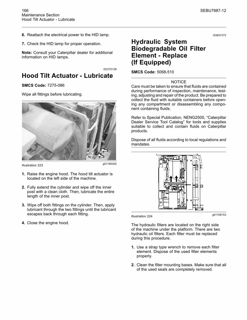
166 SEBU7887-12Maintenance SectionHood Tilt Actuator - Lubricate
6. Reattach the electrical power to the HID lamp.
7. Check the HID lamp for proper operation.
Note: Consult your Caterpillar dealer for additionalinformation on HID lamps.
i02375128
Hood Tilt Actuator - LubricateSMCS Code: 7275-086
Wipe all fittings before lubricating.
g01185302Illustration 223
1. Raise the engine hood. The hood tilt actuator islocated on the left side of the machine.
2. Fully extend the cylinder and wipe off the innerpost with a clean cloth. Then, lubricate the entirelength of the inner post.
3. Wipe off both fittings on the cylinder. Then, applylubricant through the two fittings until the lubricantescapes back through each fitting.
4. Close the engine hood.
i03657272
Hydraulic SystemBiodegradable Oil FilterElement - Replace(If Equipped)SMCS Code: 5068-510
NOTICECare must be taken to ensure that fluids are containedduring performance of inspection, maintenance, test-ing, adjusting and repair of the product. Be prepared tocollect the fluid with suitable containers before open-ing any compartment or disassembling any compo-nent containing fluids.
Refer to Special Publication, NENG2500, “CaterpillarDealer Service Tool Catalog” for tools and suppliessuitable to collect and contain fluids on Caterpillarproducts.
Dispose of all fluids according to local regulations andmandates.
g01108153Illustration 224
The hydraulic filters are located on the right sideof the machine under the platform. There are twohydraulic oil filters. Each filter must be replacedduring this procedure.
1. Use a strap type wrench to remove each filterelement. Dispose of the used filter elementsproperly.
2. Clean the filter mounting bases. Make sure that allof the used seals are completely removed.

SEBU7887-12 167Maintenance Section
Hydraulic System Oil - Change
g00101318Illustration 225
3. Apply a thin coat of hydraulic oil to the seals onthe new filters. Install each new hydraulic oil filterhand tight until the seals of the hydraulic oil filterscontact each filter base. Note the position of theindex marks on each filter in relation to a fixedpoint on each filter base.
Note: There are rotation index marks on eachhydraulic oil filter that are spaced 90 degrees or 1/4of a turn away from each other. When you tightenthe hydraulic oil filters, use the rotation index marksas a guide.
4. Tighten each filter according to the instructionsthat are printed on each filter. Use the index marksas a guide. For non-Caterpillar filters, use theinstructions that are provided with the filter.
Note: You may need to use a Caterpillar strapwrench, or another suitable tool, in order to turnthe filter to the amount that is required for finalinstallation. Make sure that the installation tool doesnot damage the filter.
5. Start the engine and run the engine at low idle.Inspect the hydraulic system for leaks.
g01185406Illustration 226
6. Maintain the oil level above the “ADD COLD” markon the sight gauge. Add hydraulic oil, if necessary.
i03563580
Hydraulic System Oil - ChangeSMCS Code: 5056-044
Selection of the Oil Change IntervalYour machine may be able to use a 4000 hourinterval for the hydraulic oil. The hydraulic oil is inthe system that is not integral to the service brakes,the clutches, the final drives, or the differentials.The standard change interval is 2000 hours. The oilshould be monitored during intervals of 500 hours.The extended 4000 hour interval can be used if thefollowing criteria are met.
HYDO Advanced 10
Cat HYDO Advanced 10 is the preferred oil for use inmost Caterpillar machine hydraulic and hydrostatictransmission systems when ambient temperatureis between −20 °C (−4 °F) and 40 °C (104 °F). CatHYDO Advanced 10 has an SAE viscosity grade of10W. Cat HYDO Advanced 10 has a 50% increasein the standard oil drain interval (up to 3000 hours)for machine hydraulic systems over second and thirdchoice oils when you follow the maintenance intervalschedule for oil filter changes and for oil sampling thatis stated in the Operation and Maintenance Manual.6000 hour oil drain intervals are possible when usingS·O·S Services oil analysis. When you switch to CatHYDO Advanced 10, cross contamination with theprevious oil should be kept to less than 10%. Consultyour Cat dealer for details about the benefits fromthe improved performance designed into Cat HYDOAdvanced 10.
Oil Filters
Caterpillar oil filters are recommended. The intervalfor changing the oil filter should be 500 hours.
Oil
The 6000 hour interval for changing the oil is specificto HYDO Advanced 10.
The 4000 hour interval for changing the oil is for thefollowing oil types.
• Caterpillar Hydraulic Oil (HYDO)
• Caterpillar Transmission and Drive Train Oil(TDTO)
• Caterpillar TDTO-TMS
• Caterpillar Diesel Engine Oil

168 SEBU7887-12Maintenance SectionHydraulic System Oil - Change
• Caterpillar Biodegradable Hydraulic Oils (HEES)
• Caterpillar Multipurpose Tractor Oil (MTO)
• Heavy-duty diesel engine oils with a minimum zinccontent of 900 ppm
If Caterpillar oils cannot be used, use heavy-duty oilswith the following classification: Caterpillar ECF-1,API CG-4, API CF, and TO-4. These oils must havea minimum zinc additive of 0.09 percent (900 ppm).
Note: Industrial hydraulic oils are not recommendedin Caterpillar hydraulic systems.
Monitoring the Condition of the Oil
The oil should be monitored during intervals of 500hours. Caterpillar's standard SOS Fluids Analysis oran equivalent oil sampling program should be used.
The current guidelines for cleanliness of the oilshould be observed. Refer to “Measured Data”.
If an oil sampling program is not available, thestandard 2000 oil change interval should be used.
Measured Data
The following information should be monitoredthrough sampling of the oil:
• Significant changes in wear metals should bemonitored. These metals include iron, copper,chromium, lead, aluminum, and tin.
• Significant changes in the following additivesshould be monitored: zinc, calcium, magnesium,and phosphorus.
• Contaminants should not be present. Thesecontaminants include fuel and antifreeze. Watercontent should be .5 percent or less.
• The silicon level should not exceed 15 parts permillion for new oil. The particle counts should bemonitored.
• The recommended level of cleanliness forCaterpillar machines that are operated in the fieldis ISO 18/15 or cleaner. The cleanliness should bemonitored by particle count analysis. The levelsof contamination should not exceed the normalby more than two ISO codes. Action should betaken in order to determine the cause of thecontamination. The system should be returned tothe original levels of contamination.
• There should not be significant changes in sodium,silicon, copper, and potassium.
• The allowable level of oxidation is 40 percent (0.12Abs units).
• The kinematic viscosity of 100 °C (212 °F) oilshould not exceed a change of more than 2 cStfrom new oil.
Procedure for Changing theHydraulic Oil
NOTICECare must be taken to ensure that fluids are containedduring performance of inspection, maintenance, test-ing, adjusting and repair of the product. Be prepared tocollect the fluid with suitable containers before open-ing any compartment or disassembling any compo-nent containing fluids.
Refer to Special Publication, NENG2500, “CaterpillarDealer Service Tool Catalog” for tools and suppliessuitable to collect and contain fluids on Caterpillarproducts.
Dispose of all fluids according to local regulations andmandates.
1. Operate the machine in order to warm thehydraulic oil.
2. Park the machine on level ground. Lower theattachment to the ground and apply slightdownward pressure. Engage the parking brakeand stop the engine.
g01185530Illustration 227

SEBU7887-12 169Maintenance Section
Hydraulic System Oil - Change
g01185539Illustration 228
3. The hydraulic tank is behind the cab of themachine. Press the button on breaker relief valve(1) in order to relieve any tank pressure.
4. Remove hydraulic tank filler cap (2) and the fillerstrainer. The filler strainer is located right beneaththe hydraulic tank filler cap. Wash the filler capand the strainer in a clean, nonflammable solvent.Install the strainer.
5. Inspect the gasket on the hydraulic tank filler capfor damage. Replace the gasket, if necessary.
g01108775Illustration 229
6. The hydraulic tank has a remote drain plug whichis located on the right side of the machine underthe platform. Remove drain plug (4). Wash thedrain plug in a clean, nonflammable solvent.
7. The hydraulic tank is equipped with an ecologydrain valve. Attach a hose to a suitable drainadapter. Install the adapter in the drain valve andallow the oil to drain into a suitable container.
8. After you have drained the oil, remove the adapterfrom the drain opening.
NOTICENever start the engine while the hydraulic oil tank isbeing drained or while the hydraulic oil tank is empty.Excessive wear and damage to the hydraulic compo-nents can occur.
9. Close the drain valve. Install the drain plug.
10.Change the hydraulic oil filter.
Reference: Refer to Operation and MaintenanceManual, “Hydraulic System Oil Filter - Replace” forthe correct procedure.
11. Fill the hydraulic tank with clean oil. Make surethat the oil level is at the “FULL” mark on sightgauge (3). Install the filler cap.
Reference: Refer to Operation and MaintenanceManual, “Lubricant Viscosities and RefillCapacities” for the correct type of oil and for thecorrect amount of oil.
12.Start the engine and run the engine for at least tenseconds. Then, stop the engine and add hydraulicoil to the tank until the oil level is at the “FULL”mark on the sight gauge. Install the filler cap.
13.Start the engine and run the engine at low idle.Cycle the implements so that all hydraulic systemsare filled with oil.
Note: If the alert indicator for a low oil level comeson, stop the engine and immediately add oil to thehydraulic tank. The oil level should not be below thesuction ports in the hydraulic tank while the engineis running.
14.Add hydraulic oil to the tank until the oil level is atthe “FULL” mark on the sight gauge.
15.Stop the engine. Top off the hydraulic tank sothat the oil level is at the “FULL” mark on the sightgauge. Install the filler cap.
Note: The oil must be free of air bubbles. If airbubbles are present in the hydraulic oil, air is enteringthe hydraulic system. Inspect the hydraulic suctionline and the hose clamps.
16. If necessary, tighten any loose clamps or anyloose connections. Replace any damaged hoses.
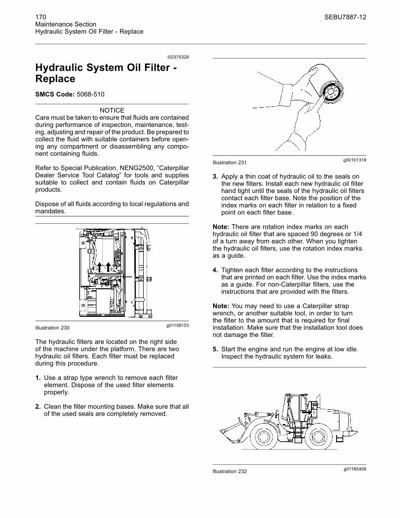
170 SEBU7887-12Maintenance SectionHydraulic System Oil Filter - Replace
i02375329
Hydraulic System Oil Filter -ReplaceSMCS Code: 5068-510
NOTICECare must be taken to ensure that fluids are containedduring performance of inspection, maintenance, test-ing, adjusting and repair of the product. Be prepared tocollect the fluid with suitable containers before open-ing any compartment or disassembling any compo-nent containing fluids.
Refer to Special Publication, NENG2500, “CaterpillarDealer Service Tool Catalog” for tools and suppliessuitable to collect and contain fluids on Caterpillarproducts.
Dispose of all fluids according to local regulations andmandates.
g01108153Illustration 230
The hydraulic filters are located on the right sideof the machine under the platform. There are twohydraulic oil filters. Each filter must be replacedduring this procedure.
1. Use a strap type wrench to remove each filterelement. Dispose of the used filter elementsproperly.
2. Clean the filter mounting bases. Make sure that allof the used seals are completely removed.
g00101318Illustration 231
3. Apply a thin coat of hydraulic oil to the seals onthe new filters. Install each new hydraulic oil filterhand tight until the seals of the hydraulic oil filterscontact each filter base. Note the position of theindex marks on each filter in relation to a fixedpoint on each filter base.
Note: There are rotation index marks on eachhydraulic oil filter that are spaced 90 degrees or 1/4of a turn away from each other. When you tightenthe hydraulic oil filters, use the rotation index marksas a guide.
4. Tighten each filter according to the instructionsthat are printed on each filter. Use the index marksas a guide. For non-Caterpillar filters, use theinstructions that are provided with the filters.
Note: You may need to use a Caterpillar strapwrench, or another suitable tool, in order to turnthe filter to the amount that is required for finalinstallation. Make sure that the installation tool doesnot damage the filter.
5. Start the engine and run the engine at low idle.Inspect the hydraulic system for leaks.
g01185406Illustration 232

SEBU7887-12 171Maintenance Section
Hydraulic System Oil Level - Check
6. The oil gauge and the hydraulic oil filler are onthe left side of the machine above the platform.Maintain the oil level above the “ADD COLD” markon the sight gauge. Add hydraulic oil, if necessary.
i02375341
Hydraulic System Oil Level -CheckSMCS Code: 5056-535-FLV
g01185406Illustration 233
g01185435Illustration 234
The hydraulic tank is located on the left side of themachine behind the cab.
The lift arms must be lowered with the bucket flat inorder to check the hydraulic oil. Check the hydraulicoil level while the engine is stopped. Maintain the oillevel above the “ADD COLD” mark on sight gauge(2). If necessary, remove filler cap (1) slowly and addoil.
i02375351
Hydraulic System Oil Sample- ObtainSMCS Code: 5050-008; 5056-008; 7542
NOTICECare must be taken to ensure that fluids are containedduring performance of inspection, maintenance, test-ing, adjusting and repair of the product. Be prepared tocollect the fluid with suitable containers before open-ing any compartment or disassembling any compo-nent containing fluids.
Refer to Special Publication, NENG2500, “CaterpillarDealer Service Tool Catalog” for tools and suppliessuitable to collect and contain fluids on Caterpillarproducts.
Dispose of all fluids according to local regulations andmandates.
1. Operate the machine for a few minutes beforeobtaining the oil sample. Operate the hydrauliccontrols. This will thoroughly mix the hydraulic oilfor a more accurate sample.
g01185445Illustration 235
2. If the machine is equipped with conventional oil,open the access door to the service center onthe right side of the machine. The hydraulic oilfilter is above the shelf. The sampling valve for thehydraulic oil is located on the hydraulic oil filterbase.
3. If the machine is equipped with biodegradablehydraulic oil, open the access door to the servicecenter on the right side of the machine. Thehydraulic oil filter is above the shelf. The samplingvalve for the hydraulic oil is located on thehydraulic oil filter base.
4. Use the in-line sampling valve in order to obtain asample of hydraulic oil.

172 SEBU7887-12Maintenance SectionHydraulic Tank Breaker Relief Valve - Clean
5. Close the access door to the service center on theright side of the machine.
Reference: For more information, refer to SpecialPublication, SEBU6250, “Caterpillar Machine FluidsRecommendations”, “S·O·S Oil Analysis” and SpecialPublication, PEHP6001, “How To Take A Good OilSample”.
i02375419
Hydraulic Tank Breaker ReliefValve - CleanSMCS Code: 5118-070
g01185542Illustration 236
The hydraulic tank breaker relief valve is located onthe top of the hydraulic tank behind the cab of themachine.
1. Press the button on the top of the hydraulicbreaker in order to relieve the pressure in thehydraulic tank. Remove the hydraulic tank breakerrelief valve.
2. Clean the hydraulic tank breaker relief valve in aclean, nonflammable solvent. Shake the breakerrelief valve dry or use pressure air to dry thebreaker relief valve.
3. Install the hydraulic tank breaker relief valve.
i03657276
Logging Fork Clamp -Lubricate(If Equipped)SMCS Code: 6113-086-BD; 6410-086-BD
Wipe off all fittings before any lubricant is applied.
g01962679Illustration 237
Apply lubricant through three fittings on each sideof the logging fork.
There is a total of six fittings.
i02106227
Oil Filter - InspectSMCS Code: 1308-507; 3004-507; 3067-507;5068-507
Inspect a Used Filter for Debris
g00100013Illustration 238
The element is shown with debris.
Use a filter cutter to cut the filter element open.Spread apart the pleats and inspect the element formetal and for other debris. An excessive amount ofdebris in the filter element can indicate a possiblefailure.
If metals are found in the filter element, a magnet canbe used to differentiate between ferrous metals andnonferrous metals.
Ferrous metals can indicate wear on steel parts andon cast iron parts.
SEBU7887-12 173Maintenance Section
Quick Coupler - Check
Nonferrous metals can indicate wear on thealuminum parts of the engine such as main bearings,rod bearings, or turbocharger bearings.
Small amounts of debris may be found in the filterelement. This could be caused by friction and bynormal wear. Consult your Caterpillar dealer in orderto arrange for further analysis if an excessive amountof debris is found.
Using an oil filter element that is not recommendedby Caterpillar can result in severe engine damageto engine bearings, to the crankshaft, and to otherparts. This can result in larger particles in unfilteredoil. The particles could enter the lubricating systemand the particles could cause damage.
i03657277
Quick Coupler - Check(If Equipped)SMCS Code: 6129-535
When you install a work tool on the quick coupler,inspect the engagement of the coupler pins. If there isplay between the coupler pins and the correspondingbores, inspect the coupler pins and the bores fordamage or wear.
If there is play between the quick coupler and thehooks of the work tool, inspect the quick coupler andthe hooks for wear or for damage.
Make any necessary repairs before you operate thework tool.
i03657285
Quick Coupler - Lubricate(If Equipped)SMCS Code: 6129-086
Note: Refer to Operation and Maintenance Manual,“Lubricant Viscosities” for more information onthe types of grease to use. Refer to SpecialPublication, SEBU6250, “Caterpillar Machine FluidsRecommendations” for more information on grease.
Wipe off all lubricant fittings before you applylubricant through the lubricant fittings.
Do not lubricate the wedge and the wear plates.Friction is needed in order to hold the wedge in placeduring backfilling.
i02191167
Radiator Core - CleanSMCS Code: 1353-070-KO
1. Open the radiator grill at the rear of the machine.
g01107157Illustration 239
2. Use the control knob (1) in order to release thehydraulic oil cooler. Swing hydraulic oil cooler (2)and condenser (3) away from the radiator.
g00101939Illustration 240
3. You can use compressed air, high pressure water,or steam to remove dust and other debris fromthe radiator fins. However, the use of compressedair is preferred.
4. Swing the hydraulic oil cooler and the airconditioner condenser (if equipped) back into theoperating position.
5. Close the radiator grill.

174 SEBU7887-12Maintenance SectionReceiver Dryer (Refrigerant) - Replace
i02894326
Receiver Dryer (Refrigerant) -ReplaceSMCS Code: 7322-510
Personal injury can result from contact with refrig-erant.
Contact with refrigerant can cause frost bite. Keepface and hands away to help prevent injury.
Protective goggles must always be worn when re-frigerant lines are opened, even if the gauges in-dicate the system is empty of refrigerant.
Always use precaution when a fitting is removed.Slowly loosen the fitting. If the system is still un-der pressure, release it slowly in a well ventilatedarea.
Personal injury or death can result from inhalingrefrigerant through a lit cigarette.
Inhaling air conditioner refrigerant gas through alit cigarette or other smoking method or inhalingfumes released from a flame contacting air con-ditioner refrigerant gas, can cause bodily harm ordeath.
Do not smoke when servicing air conditioners orwherever refrigerant gas may be present.
Use a certified recovery and recycling cart to prop-erly remove the refrigerant from the air condition-ing system.
g01107270Illustration 241
(1) Refrigerant accumulator(2) Refrigerant dryer
Access refrigerant accumulator (1) from the left sideof the machine. Access in-line refrigerant dryer (2)from the right side of the machine.
Refer to Service Manual, SENR5664, “RefrigerantAccumulator - Remove and Install” for thereplacement procedure of accumulator (1).
Refer to Service Manual, SENR5664, “In-LineRefrigerant Dryer - Remove and Install” for thereplacement procedure of refrigerant dryer (2).
Note: When you operate the machine in a climatewith high humidity, replace the in-line refrigerant dryerafter every 1000 service hours or 6 months.
i02747279
Ride Control Accumulator -CheckSMCS Code: 5077-535-R6
Note: When the ride control accumulator is properlycharged, the bouncing motion of the machine isreduced by the ride control accumulator.
1. Put a typical load in the bucket.
2. Press the bottom of the ride control switch in orderto activate the ride control function.
3. Drive the machine over a rough road surface.
If the machine bounces too much or theaccumulator piston striking the stop can be heard,consult your Caterpillar dealer or refer to ServiceManual Testing and Adjusting, “Ride ControlAccumulator - Test and Charge”.
i03657286
Roading Fender Hinges -Lubricate(If Equipped)SMCS Code: 7252-086-RNG
Wipe off the fitting before any lubricant is applied.
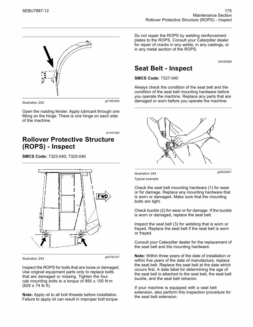
SEBU7887-12 175Maintenance Section
Rollover Protective Structure (ROPS) - Inspect
g01963400Illustration 242
Open the roading fender. Apply lubricant through onefitting on the hinge. There is one hinge on each sideof the machine.
i01457460
Rollover Protective Structure(ROPS) - InspectSMCS Code: 7323-040; 7325-040
g00762107Illustration 243
Inspect the ROPS for bolts that are loose or damaged.Use original equipment parts only to replace boltsthat are damaged or missing. Tighten the fourcab mounting bolts to a torque of 850 ± 100 N·m(629 ± 74 lb ft).
Note: Apply oil to all bolt threads before installation.Failure to apply oil can result in improper bolt torque.
Do not repair the ROPS by welding reinforcementplates to the ROPS. Consult your Caterpillar dealerfor repair of cracks in any welds, in any castings, orin any metal section of the ROPS.
i02429589
Seat Belt - InspectSMCS Code: 7327-040
Always check the condition of the seat belt and thecondition of the seat belt mounting hardware beforeyou operate the machine. Replace any parts that aredamaged or worn before you operate the machine.
g00932801Illustration 244Typical example
Check the seat belt mounting hardware (1) for wearor for damage. Replace any mounting hardware thatis worn or damaged. Make sure that the mountingbolts are tight.
Check buckle (2) for wear or for damage. If the buckleis worn or damaged, replace the seat belt.
Inspect the seat belt (3) for webbing that is worn orfrayed. Replace the seat belt if the seat belt is wornor frayed.
Consult your Caterpillar dealer for the replacement ofthe seat belt and the mounting hardware.
Note:Within three years of the date of installation orwithin five years of the date of manufacture, replacethe seat belt. Replace the seat belt at the date whichoccurs first. A date label for determining the age ofthe seat belt is attached to the seat belt, the seat beltbuckle, and the seat belt retractor.
If your machine is equipped with a seat beltextension, also perform this inspection procedure forthe seat belt extension.

176 SEBU7887-12Maintenance SectionSeat Belt - Replace
i02429594
Seat Belt - ReplaceSMCS Code: 7327-510
Within three years of the date of installation or withinfive years of the date of manufacture, replace theseat belt . Replace the seat belt at the date whichoccurs first. A date label for determining the age ofthe seat belt is attached to the seat belt, the seat beltbuckle, and the seat belt retractor.
g01152685Illustration 245(1) Date of installation (retractor)(2) Date of installation (buckle)(3) Date of manufacture (tag) (fully extended web)(4) Date of manufacture (underside) (buckle)
Consult your Caterpillar dealer for the replacement ofthe seat belt and the mounting hardware.
If your machine is equipped with a seat beltextension, also perform this replacement procedurefor the seat belt extension.
i03694709
Secondary Steering - TestSMCS Code: 4300-081-SE; 4300-081-SST;4324-081; 4324
The service brake must be checked in order to en-sure proper operation before you test the supple-mental steering system.
Personal injury, death, or property damage couldoccur if the supplemental steering system is test-ed and the service brake is not operational.
Test the service brake before you test the supple-mental steering system.
Perform the following procedure if your machine isequipped with a ground driven supplemental steeringand if the procedure is required by local regulations.
Ensure that there are no hazards in the test area. Thetest area must be unobstructed and level. Operatethe machine in second gear.
Ensure that all air tanks and accumulators areproperly charged. Ensure that there is no load in thework tool. Position the machine with the bucket or thework tool in the carry position with the machine inneutral. Release the parking brake. Apply the servicebrakes and put the engine at low idle. Ensure that Thearea around the machine is clear of personnel. Shiftthe transmission to second gear forward and slowlyrelease the service brakes. Moderately increase theengine speed to high idle. Shift the transmission toneutral. Turn the ignition to the OFF position. Allowthe machine to coast.
While the machine is in motion, turn the machine tothe left and to the right. If the machine responds tothe steering input, the supplemental steering systemis operating. Stop the machine with the servicebrakes. Apply the parking brake. The machine canthen be returned to normal operation.
If there is no response to the steering input, thesupplemental steering system is not operating. Stopthe machine immediately. Repair the supplementalsteering system before returning the machine toservice.
i02837395
Steering Column Play - CheckSMCS Code: 4310-535; 4338-535
g01411297Illustration 246
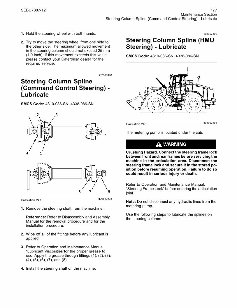
SEBU7887-12 177Maintenance Section
Steering Column Spline (Command Control Steering) - Lubricate
1. Hold the steering wheel with both hands.
2. Try to move the steering wheel from one side tothe other side. The maximum allowed movementin the steering column should not exceed 25 mm(1.0 inch). If this movement exceeds this valueplease contact your Caterpillar dealer for therequired service.
i02585698
Steering Column Spline(Command Control Steering) -LubricateSMCS Code: 4310-086-SN; 4338-086-SN
g00812993Illustration 247
1. Remove the steering shaft from the machine.
Reference: Refer to Disassembly and AssemblyManual for the removal procedure and for theinstallation procedure.
2. Wipe off all of the fittings before any lubricant isapplied.
3. Refer to Operation and Maintenance Manual,“Lubricant Viscosities”for the proper grease touse. Apply the grease through fittings (1), (2), (3),(4), (5), (6), (7), and (8).
4. Install the steering shaft on the machine.
i03657300
Steering Column Spline (HMUSteering) - LubricateSMCS Code: 4310-086-SN; 4338-086-SN
g01962195Illustration 248
The metering pump is located under the cab.
Crushing Hazard. Connect the steering frame lockbetween front and rear frames before servicing themachine in the articulation area. Disconnect thesteering frame lock and secure it in the stored po-sition before resuming operation. Failure to do socould result in serious injury or death.
Refer to Operation and Maintenance Manual,“Steering Frame Lock” before entering the articulationjoint.
Note: Do not disconnect any hydraulic lines from themetering pump.
Use the following steps to lubricate the splines onthe steering column:

178 SEBU7887-12Maintenance SectionSteering Cylinder Bearings - Lubricate
g01294342Illustration 249(1) Panel(2) Bolts
1. Remove five bolts (2) and panel (1) from eachside of the machine.
g01294346Illustration 250
g01294352Illustration 251
2. Support the metering pump (3). Do not loosen thehose couplings (5).
3. Loosen the four bolts (4) that hold the pump.
g01294357Illustration 252
4. Lower the pump in order to expose the splines (6).
5. Clean the male splines on the steering column.Clean the female splines in the pump.
6. Apply proper grease to the splines. Refer toOperation and Maintenance Manual, “LubricantViscosities” for selecting the proper grease.
7. Push the pump into position.
8. Tighten the four bolts that hold the pump.
9. Test the steering system.
i03657091
Steering Cylinder Bearings -LubricateSMCS Code: 4303-086-BD
Crushing Hazard. Connect the steering frame lockbetween front and rear frames before servicing themachine in the articulation area. Disconnect thesteering frame lock and secure it in the stored po-sition before resuming operation. Failure to do socould result in serious injury or death.
Refer to Operation and Maintenance Manual,“Steering Frame Lock” before entering the articulationjoint.
Crushing Hazard. Insure that the machine ignitionswitch is in the OFF position and that the parkingbrake is engaged before entering the articulationarea. Failure to do so could result in serious injuryor death.

SEBU7887-12 179Maintenance Section
Steering Pilot Oil Screen (Command Control Steering) - Clean/Replace
g01105600Illustration 253(1) Location of the grease fittings for the rod ends(2) Remote location of the grease fittings for the head ends
g01105611Illustration 254
Location of the grease fittings for the rod ends (both sides)
g01105595Illustration 255Remote location of the grease fittings for the rod ends
Wipe off the fittings before any lubricant is applied.The rod end of the steering cylinders are lubricatedby using standard grease fittings (3).
The head ends of the steering cylinders are lubricatedby using remote grease fittings (4) that are located onthe right side of the machine in front of the steps.
i03657340
Steering Pilot Oil Screen(Command Control Steering) -Clean/Replace(If Equipped)SMCS Code: 4304-070-Z3; 4304-510-Z3
Crushing Hazard. Connect the steering frame lockbetween front and rear frames before servicing themachine in the articulation area. Disconnect thesteering frame lock and secure it in the stored po-sition before resuming operation. Failure to do socould result in serious injury or death.
Refer to Operation and Maintenance Manual,“Steering Frame Lock” before entering the articulationjoint.
Personal injury can result from working withcleaning solvent.
Because of the volatile nature of many cleaningsolvents, extreme caution must be exercisedwhen using them. If unsure about a particularcleaning fluid, refer to the manufacturer's instruc-tions and directions.
Always wear protective clothing and eye protec-tion when working with cleaning solvents.
g01962461Illustration 256

180 SEBU7887-12Maintenance SectionTire Inflation - Check
The screen group (3) is located behind the cab.
1. Disconnect hoses (1) and (2) that are connectedto the screen group (3).
2. Remove the two connectors that are attached tothe block.
3. Use an allen wrench in order to remove the twoscreens from screen group (3).
4. Wash the screens in a clean, nonflammablesolvent.
5. Dry each screen with pressure air. Inspect eachscreen for damage. Replace the screen if thescreen is damaged.
6. Install the screens. Install the connectors andconnect the hoses.
i02305841
Tire Inflation - CheckSMCS Code: 4203-535-AI
g01160201Illustration 257
Always obtain proper tire inflation pressures andmaintenance recommendations for the tires on yourmachine from your tire supplier. Measure the tirepressure on each tire.
Inflate the tires with nitrogen , if necessary.
Reference: Refer to the “Tire Inflation Information”section of the Operation and Maintenance Manualfor more information.
i02189470
Transmission Oil - ChangeSMCS Code: 3030-044
NOTICECare must be taken to ensure that fluids are containedduring performance of inspection, maintenance, test-ing, adjusting and repair of the product. Be prepared tocollect the fluid with suitable containers before open-ing any compartment or disassembling any compo-nent containing fluids.
Refer to Special Publication, NENG2500, “CaterpillarTools and Shop Products Guide” for tools and suppliessuitable to collect and contain fluids on Caterpillarproducts.
Dispose of all fluids according to local regulations andmandates.
1. Operate the engine in order to warm thetransmission oil. Park the machine on levelground. Lower the bucket and apply slightdownward pressure.
2. Engage the parking brake. Stop the engine.
g01002772Illustration 258
3. Remove drain plug (1) on the bottom of thetransfer case.
4. Change the transmission oil filter.
Reference: Refer to Operation and MaintenanceManual, “Transmission Oil Filter - Replace” for thecorrect procedure.

SEBU7887-12 181Maintenance Section
Transmission Oil - Change
g00884724Illustration 259
5. The magnetic strainer is on the right rear sideof the transfer case. Remove the four bolts, thecover and the seal that holds the magnets andthe screen in place.
6. Remove the screen and the magnets from thetransfer case housing.
7. Wash the screen in a clean, nonflammablesolvent. Use a bristle brush or pressure air toclean the screen. Clean the magnets. Replaceany damaged magnets.
8. Clean the cover. Inspect the cover seal. Replacethe cover seal if the seal is damaged.
9. Insert the magnets and the screen into the transfercase housing. Install the seal, the cover and thefour bolts.
10.Clean the transmission oil drain plug and installthe transmission oil drain plug.
g01106816Illustration 260
11.Remove the oil filler cap on the left side of themachine and fill the transmission with oil.
Reference: Refer to Operation and MaintenanceManual, “Lubricant Viscosities and RefillCapacities” for the type of lubricant and for therefill capacity.
g01002778Illustration 261
12.Remove the breather from the top of the transfercase. Wash the breather in a clean, nonflammablesolvent. Install the breather.
13.Start and run the engine at low idle. Inspect themachine for leaks. Slowly operate the transmissioncontrols in order to circulate the transmission oil.
14.Check the transmission oil level.
Reference: Refer to Operation and MaintenanceManual, “Transmission Oil Level - Check” for thecorrect procedure.

182 SEBU7887-12Maintenance SectionTransmission Oil Filter - Replace
i02194865
Transmission Oil Filter -ReplaceSMCS Code: 3004-510; 3067-510
NOTICECare must be taken to ensure that fluids are containedduring performance of inspection, maintenance, test-ing, adjusting and repair of the product. Be prepared tocollect the fluid with suitable containers before open-ing any compartment or disassembling any compo-nent containing fluids.
Refer to Special Publication, NENG2500, “CaterpillarTools and Shop Products Guide” for tools and suppliessuitable to collect and contain fluids on Caterpillarproducts.
Dispose of all fluids according to local regulations andmandates.
g01108389Illustration 262
The transmission oil filter is located on the right sideof the machine under the platform.
1. Operate the machine in order to warm the oil. Parkthe machine on level ground. Lower the bucket tothe ground and apply slight downward pressure.
2. Engage the parking brake and stop the engine.
3. Open the access panel.
4. Remove the filter housing drain plug and allow theoil in the filter to drain into a suitable container.
5. Use a strap type wrench to remove the filterhousing.
6. Remove the used filter element. Dispose of theused filter element properly.
7. Clean the filter housing and the filter housing basewith a clean, nonflammable solvent.
8. Inspect the filter housing seal. Replace the sealif the seal is damaged.
9. Install the new filter element into the transmissionfilter housing. Clean the filter housing drain plugand install the drain plug.
10.Start the engine. Slowly operate the transmissioncontrols in order to circulate the transmission oil.Check the machine for oil leaks.
11.Check the transmission oil level.
Reference: Refer to Operation and MaintenanceManual, “Transmission Oil Level - Check” for thecorrect procedure.
i01468938
Transmission Oil Level - CheckSMCS Code: 3030-535-FLV
g00766406Illustration 263
The sight gauge for the transmission oil level islocated on the left side of the machine near thearticulation joint.
1. Operate the machine for a few minutes in order towarm the transmission oil.
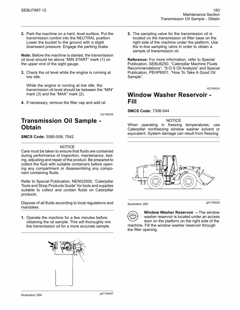
SEBU7887-12 183Maintenance Section
Transmission Oil Sample - Obtain
2. Park the machine on a hard, level surface. Put thetransmission control into the NEUTRAL position.Lower the bucket to the ground with a slightdownward pressure. Engage the parking brake.
Note: Before the machine is started, the transmissionoil level should be above “MIN START” mark (1) onthe upper end of the sight gauge.
3. Check the oil level while the engine is running atlow idle.
While the engine is running at low idle, thetransmission oil level should be between the “MIN”mark (3) and the “MAX” mark (2).
4. If necessary, remove the filler cap and add oil.
i02195036
Transmission Oil Sample -ObtainSMCS Code: 3080-008; 7542
NOTICECare must be taken to ensure that fluids are containedduring performance of inspection, maintenance, test-ing, adjusting and repair of the product. Be prepared tocollect the fluid with suitable containers before open-ing any compartment or disassembling any compo-nent containing fluids.
Refer to Special Publication, NENG2500, “CaterpillarTools and Shop Products Guide” for tools and suppliessuitable to collect and contain fluids on Caterpillarproducts.
Dispose of all fluids according to local regulations andmandates.
1. Operate the machine for a few minutes beforeobtaining the oil sample. This will thoroughly mixthe transmission oil for a more accurate sample.
g01108497Illustration 264
2. The sampling valve for the transmission oil islocated on the transmission oil filter base on theright side of the machine under the platform. Usethe in-line sampling valve in order to obtain asample of transmission oil.
Reference: For more information, refer to SpecialPublication, SEBU6250, “Caterpillar Machine FluidsRecommendations”, “S·O·S Oil Analysis” and SpecialPublication, PEHP6001, “How To Take A Good OilSample”.
i02189520
Window Washer Reservoir -FillSMCS Code: 7306-544
NOTICEWhen operating in freezing temperatures, useCaterpillar nonfreezing window washer solvent orequivalent. System damage can result from freezing.
g01106828Illustration 265
Window Washer Reservoir – The windowwasher reservoir is located under an accessdoor on the platform on the right side of the
machine. Fill the window washer reservoir throughthe filler opening.

184 SEBU7887-12Maintenance SectionWindow Wiper - Inspect/Replace
i03657573
Window Wiper -Inspect/ReplaceSMCS Code: 7305-040; 7305-510
g01962467Illustration 266
Inspect the condition of the wiper blades on the frontwindow and on the rear window. Replace the wiperblades if the wiper blades are worn or damaged orif streaking occurs.
i00037755
Windows - CleanSMCS Code: 7310-070
g00038949Illustration 267
Use commercially available window cleaningsolutions in order to clean the windows. Clean theoutside windows from the ground unless handholdsare available.