93049 BORKE JOB - Letherer BORKE JOB MU S 26 MU S 26 TJC37 TJC37 2 ... N 24 -3269 N - O 21 -3284 O -...
23
24'4" 8' 15'8" 24'4" 8' 10'8" 7' 7' 19' 10' 7' 7'1" 2' 31' 24'9"8 16'1"8 2' 2'3"8 2x10 LEDGER 93049 BORKE JOB MUS26 MUS26 TJC37 TJC37 2' 2' 1'6" 1'6" 2' 2' 2' 10"8 2' 10'2" 18'10" 2' 9" 2' 2' 2' 2' 2' 2' 2' 1'1"6 10"10 2' 2' 2' 7"2 1'6"6 2' 2' 2' 1'0"12 1'4" 1'4" 1'4" 1'4" 1'4" 1'4" 1'4" 1'4" 1'4" 1'4" 1'4" 1'3"4 1'11"4 2' 2' 1' 1' 2' 2' 1'11"4 EJ1 EJ2 EJ2 EJ2 EJ2 EJ3 EJ3 EJ3 EJ3 EJ4 EJ4 EJ4 EJ4 HJ1 HJ1 GS1 G1 P2 ATG ATG T3 TG1 G2 G2 TG1 3 PLY 3 PLY S1 AT1 AT1 T2 T2 T1 P1 P1 AT2 PAGE NO: 1 OF 1 JOB NO: 93049 Lot: THOMAS SHARLENE BORKE Layout: NL Designer: JARED JORGENSEN Contractor: MCCLOUD Customer: MCBAIN BLDG PRODUCTS Address: 7408 MISSAUKEE BLVD
Transcript of 93049 BORKE JOB - Letherer BORKE JOB MU S 26 MU S 26 TJC37 TJC37 2 ... N 24 -3269 N - O 21 -3284 O -...

24'4
"8'
15'8
"
24'4
"8'
10'8
"7'
7'
19' 10'
7'
7'1"
2'
31'
24'9
"816
'1"8
2'
2'3"8
2x10 LEDGER
93049BORKE JOB
MU
S26
MU
S26
TJC37TJC37
2' 2'
1'6"
1'6" 2' 2'2'
10"8 2'
10'2"18'10"
2'9"2'
2'
2'
2'
2'
2'
2'1'1"610"10
2'
2'
2'7"2
1'6"6
2'
2'
2'1'0"12
1'4"1'4"1'4"1'4"1'4"1'4"1'4"1'4"1'4"1'4"1'4"
1'3"4
1'11
"4 2' 2' 1' 1' 2' 2'
1'11
"4
EJ1
EJ2
EJ2EJ2
EJ2
EJ3 EJ3
EJ3
EJ3
EJ4
EJ4EJ4
EJ4
HJ1 HJ1GS1
G1
P2
ATG
ATG
T3
TG1 G
2
G2
TG1
3 PLY
3 PLY
S1AT
1AT
1
T2T2
T1P1
P1
AT2
PAGE NO:
1 OF 1
JOB NO:
93049
Lot
: TH
OM
AS S
HAR
LEN
E BO
RKE
L
ayou
t: N
L
Des
igne
r: JA
RED
JO
RG
ENSE
N
C
ontra
ctor
: MC
CLO
UD
C
usto
mer
: MC
BAIN
BLD
G P
RO
DU
CTS
A
ddre
ss: 7
408
MIS
SAU
KEE
BLVD

Job:(93049) / -MCBAIN BLDG PRODUCTS /THOMAS SHARLENE BORKE / ATG 29' Attic Girder This dwg. prepared by the ITW job designer program from truss mfr's layout.Top chord 2x8 SP 2400f-2.0E :T3 2x6 SPF 1650f-1.5E:Bot chord 2x12 SP 2400f-2.0E :B2 2x4 SPF #1/#2: Webs 2x4 SPF Stud :W2, W5, W13, W16 2x4 SPF #1/#2:
Nail Schedule:0.131"x3", min. nailsTop Chord: 2 Rows @ 6.00" o.c. (Each Row)Bot Chord: 1 Row @ 6.00" o.c.Webs : 1 Row @ 4" o.c.Repeat nailing as each layer is applied. Use equal spacingbetween rows and stagger nails in each row to avoid splitting.4" o.c. spacing of nails perpendicular and parallel tograin required in area over bearings greater than 4"
All plates are 3X4 except as noted.
(**) 6 plate(s) require special positioning. Refer toscaled plate plot details for special positioning requirements.
115 mph wind, 15.00 ft mean hgt, ASCE 7-10, CLOSED bldg,Located anywhere in roof, RISK CAT II, EXP B, wind TC DL=4.2 psf,wind BC DL=6.0 psf.
Wind loads and reactions based on MWFRS with additional C&Cmember design.
End verticals not exposed to wind pressure. In lieu of structural panels or rigid ceiling use purlinsto laterally brace chords as follows: CHORD SPACING(IN OC) START(FT) END(FT) TC 24 10.69 18.31 BC 120 0.00 29.00Apply purlins to any chords above or below fillersat 24" OC unless shown otherwise above.
Live loads applied in combination per ASCE 7 sec. 2.4.1 use 0.75factor for multiple live loads.
Trusses to be spaced at 12.0" OC maximum.
Collar-tie braced with continuous lateral bracing at 24" OC. or rigidceiling.
Deflection meets L/360 live and L/240 total load. Creep increasefactor for dead load is 2.00.
PLT TYP. WAVEDESC = ATG 29' Attic Girder
DESIGN CRIT=IBC 2015 /TPI-2014 FT/RT=3%(0%)/0(0) PLY= 3 QTY= 0 REV. 15.02.00C.1217.15
Maximum Reactions (lbs)Loc R / U / Rw / Rh / RL / W
X 8935 / - / 7849 / - / 107 / 5.5R 8938 / - / 7853 / - / - / 5.5Wind reactions based on MWFRSX Min Brg Width Req = 3.2R Min Brg Width Req = 3.2Bearings X & R Fcperp = 565psi.
Maximum Top Chord Forces Per Ply (lbs)Chords Tens.Comp.
A - B 23 0B - C 21 - 2676C - D 21 - 3283D - E 24 - 3268E - F 35 - 2006F - G 37 - 1486G - H 263 - 104H - I 333 - 107
Chords Tens. Comp.
I - J 333 - 107J - K 263 - 104K - L 37 - 1489L - M 35 - 2009M - N 24 - 3269N - O 21 - 3284O - P 21 - 2677P - Q 23 0
Maximum Bot Chord Forces Per Ply (lbs)Chords Tens.Comp.
X - W 42 - 36W - V 1977 - 5V - U 2041 0
Chords Tens. Comp.
U - T 2041 0T - S 1975 0S - R 7 0
Maximum Web Forces Per Ply (lbs)Webs Tens.Comp.
B - X 26 - 2795B - W 2159 0W - C 0 - 1177C - V 92 - 97E - Y 1412 - 2
Webs Tens. Comp.
AB- J 205 - 12AB-AC 17 - 2411AC- K 16 - 2336AC-AD 1 - 96AD- L 0 - 14
**WARNING** READ AND FOLLOW ALL NOTES ON THIS DRAWING!**IMPORTANT** FURNISH THIS DRAWING TO ALL CONTRACTORS INCLUDING THE INSTALLERSTrusses require extreme care in fabricating, handling, shipping, installing and bracing. Refer to and follow the latest edition of BCSI (BuildingComponent Safety Information, by TPI and SBCA) for safety practices prior to performing these functions. Installers shall provide temporarybracing per BCSI. Unless noted otherwise,top chord shall have properly attached structural sheathing and bottom chord shall have a properlyattached rigid ceiling. Locations shown for permanent lateral restraint of webs shall have bracing installed per BCSI sections B3, B7, or B10,as applicable. Apply plates to each face of truss and position as shown above and on the Joint Details, unless noted otherwise. Refer todrawings 160A-Z for standard plate positions.
ITW Building Components Group Inc. shall not be responsible for any deviation from this drawing,any failure to build the truss in conformancewith ANSI/TPI 1, or for handling, shipping, installation and bracing of trusses.A seal on this drawing or cover page listing this drawing, indicates acceptance of professional engineeringresponsibility solely for the design shown.The suitability and use of this drawing for any structure is the responsibility of the Building Designer per ANSI/TPI 1 Sec.2.
TC LL 40.00 PSF
TC DL 7.00 PSF
BC DL 10.00 PSF
BC LL 0.00 PSF
TOT. LD 57.00 PSF
DUR. FAC 1.15
SPACING 12.0 "
JOB #: 93049DATE - 11/28/16
ATG 29' Attic Girder
WEIGHT =1091.0
SEQ - 37749
TYPE ATIC
3 Complete Trusses Required
17'0"
15
7'9"13
17'0"15
10'7"1 7'9"13 10'7"1
18' 11'2' 2'
29'
2'3"
8
7'6"3 13'5"4 8'0"9
8'1"
14
16'
12'
8'1"2
LEFT RAKE = 2'1"6 RIGHT RAKE = 2'1"6
A
B
CD
E
F
G
H I J
K
L
M
NO
P
Q
RSTUVWX
Y Z
AA AB AC
AD AE
11
12
6X8
H0308 5X6(**)
3X4(**)7X8
3X10
6X12(**)
1.5X3
1.5X3
3X8
6X8
3X8
10X10
6X8
3X8
1.5X3
1.5X3
6X12(**)
3X10
7X83X4(**)
5X6(**)
6X8
H0308

Job:(93049) / -MCBAIN BLDG PRODUCTS /THOMAS SHARLENE BORKE / AT2 29' Attic This dwg. prepared by the ITW job designer program from truss mfr's layout.Top chord 2x8 SP 2400f-2.0E :T3 2x6 SPF 1650f-1.5E:Bot chord 2x12 SP 2400f-2.0E :B2 2x4 SPF #1/#2: Webs 2x4 SPF Stud :W2, W5, W13, W16 2x4 SPF #1/#2:
Full Height Blocking reinforcement required toprevent buckling of members over the bearings:bearing 2 located at 18.87'
All plates are 3X4 except as noted.
(**) 6 plate(s) require special positioning. Refer toscaled plate plot details for special positioning requirements.
115 mph wind, 15.00 ft mean hgt, ASCE 7-10, CLOSED bldg,Located anywhere in roof, RISK CAT II, EXP B, wind TC DL=4.2 psf,wind BC DL=6.0 psf.
Wind loads and reactions based on MWFRS with additional C&Cmember design. End verticals not exposed to wind pressure.
In lieu of structural panels or rigid ceiling use purlinsto laterally brace chords as follows: CHORD SPACING(IN OC) START(FT) END(FT) TC 24 10.69 18.31 BC 120 0.00 29.00Apply purlins to any chords above or below fillersat 24" OC unless shown otherwise above.
Bottom chord checked for 10.00 psf non-concurrent bottom chordlive load applied per IBC-15 section 1607.Live loads applied in combination per ASCE 7 sec. 2.4.1 use 0.75
factor for multiple live loads.Collar-tie braced with continuous lateral bracing at 24" OC. or rigidceiling.Attic room loading from 6-6-0 to 22-6-0: Live Load: 40 PSF. Dead
Load: 10 PSF Ceiling: 10 PSF, Kneewalls: 10 PSFDeflection meets L/360 live and L/240 total load. Creep increasefactor for dead load is 2.00.Truss designed for unbalanced snow load based on Pg=50.00 psf,
Ct=1.10, Ce=1.00, CAT II & Pf=38.50 psf.
PLT TYP. WAVEDESC = AT2 29' Attic
DESIGN CRIT=IBC 2015 /TPI-2014 FT/RT=3%(0%)/0(0) PLY= 1 QTY= 0 REV. 15.02.00C.1217.15
Maximum Reactions (lbs)Loc R / U / Rw / Rh / RL / W
X 2121 / - / 603 / - / 214 / 5.5AF 1437 / - / 351 / - / - / 5.5R 1886 / 2 / 447 / - / - / 3.5Wind reactions based on MWFRSX Min Brg Width Req = 2.0AF Min Brg Width Req = 1.5R Min Brg Width Req = 1.8Bearings X, AF, & R Fcperp = 565psi.
Maximum Top Chord Forces Per Ply (lbs)Chords Tens.Comp.
A - B 137 0B - C 143 - 1759C - D 158 - 1944D - E 176 - 1898E - F 228 - 1462F - G 236 - 1380G - H 169 - 902H - I 212 - 943
Chords Tens. Comp.
I - J 212 - 943J - K 171 - 875K - L 237 - 1371L - M 228 - 1452M - N 182 - 1696N - O 164 - 1741O - P 155 - 1515P - Q 137 0
Maximum Bot Chord Forces Per Ply (lbs)Chords Tens.Comp.
X - W 214 - 214W - V 1238 - 92V - U 1225 - 45
Chords Tens. Comp.
U - T 2449 - 90T - S 1028 - 8S - R 3 - 1
Maximum Web Forces Per Ply (lbs)Webs Tens.Comp.
B - X 174 - 2021B - W 1359 0W - C 22 - 497
Webs Tens. Comp.
AB- J 545 - 72AB-AC 126 - 923AC- K 122 - 837
**WARNING** READ AND FOLLOW ALL NOTES ON THIS DRAWING!**IMPORTANT** FURNISH THIS DRAWING TO ALL CONTRACTORS INCLUDING THE INSTALLERSTrusses require extreme care in fabricating, handling, shipping, installing and bracing. Refer to and follow the latest edition of BCSI (BuildingComponent Safety Information, by TPI and SBCA) for safety practices prior to performing these functions. Installers shall provide temporarybracing per BCSI. Unless noted otherwise,top chord shall have properly attached structural sheathing and bottom chord shall have a properlyattached rigid ceiling. Locations shown for permanent lateral restraint of webs shall have bracing installed per BCSI sections B3, B7, or B10,as applicable. Apply plates to each face of truss and position as shown above and on the Joint Details, unless noted otherwise. Refer todrawings 160A-Z for standard plate positions.
ITW Building Components Group Inc. shall not be responsible for any deviation from this drawing,any failure to build the truss in conformancewith ANSI/TPI 1, or for handling, shipping, installation and bracing of trusses.A seal on this drawing or cover page listing this drawing, indicates acceptance of professional engineeringresponsibility solely for the design shown.The suitability and use of this drawing for any structure is the responsibility of the Building Designer per ANSI/TPI 1 Sec.2.
TC LL 40.00 PSF
TC DL 7.00 PSF
BC DL 10.00 PSF
BC LL 0.00 PSF
TOT. LD 57.00 PSF
DUR. FAC 1.15
SPACING 24.0 "
JOB #: 93049DATE - 11/28/16
AT2 29' Attic
WEIGHT =363.7
SEQ - 37762
TYPE ATIC
19'1"4 9'10"12
17'0"
15
7'9"13
17'0"15
10'7"1 7'9"13 10'7"1
18' 11'2' 2'
29'
2'3"
8
7'6"3 13'5"4 8'0"9
8'1"
14
16'
12'
8'1"2
LEFT RAKE = 2'1"6 RIGHT RAKE = 2'1"6
A
B
CD
E
F
G
H I J
K
L
M
NO
P
Q
RSTUVWX
Y Z
AA AB AC
AD AE
AF
11
12
6X8
H0308 5X6(**)
3X4(**)7X8
3X10
6X12(**)
1.5X3
1.5X3
3X8
6X8
3X8
10X10
6X8
3X8
1.5X3
1.5X3
6X12(**)
3X10
7X83X4(**)
5X6(**)
6X8
H0308

Job:(93049) / -MCBAIN BLDG PRODUCTS /THOMAS SHARLENE BORKE / AT2 29' Attic This dwg. prepared by the ITW job designer program from truss mfr's layout.
PLT TYP. WAVEDESC = AT2 29' Attic
DESIGN CRIT=IBC 2015 /TPI-2014 FT/RT=3%(0%)/0(0) PLY= 1 QTY= 0 REV. 15.02.00C.1217.15
C - V 131 - 134E - Y 763 0V - Y 745 0Y - Z 12 - 38F - Z 1 - 13Z -AA 12 - 38G -AA 125 - 726AA-AB 132 - 744H -AB 388 - 78I -AB 74 - 305
AC-AD 6 - 123AD- L 9 - 1AD-AE 6 - 123AE- T 393 - 79AE- M 469 - 79T - O 530 - 96O - S 80 - 778S - P 1125 - 9P - R 185 - 1823
**WARNING** READ AND FOLLOW ALL NOTES ON THIS DRAWING!**IMPORTANT** FURNISH THIS DRAWING TO ALL CONTRACTORS INCLUDING THE INSTALLERSTrusses require extreme care in fabricating, handling, shipping, installing and bracing. Refer to and follow the latest edition of BCSI (BuildingComponent Safety Information, by TPI and SBCA) for safety practices prior to performing these functions. Installers shall provide temporarybracing per BCSI. Unless noted otherwise,top chord shall have properly attached structural sheathing and bottom chord shall have a properlyattached rigid ceiling. Locations shown for permanent lateral restraint of webs shall have bracing installed per BCSI sections B3, B7, or B10,as applicable. Apply plates to each face of truss and position as shown above and on the Joint Details, unless noted otherwise. Refer todrawings 160A-Z for standard plate positions.
ITW Building Components Group Inc. shall not be responsible for any deviation from this drawing,any failure to build the truss in conformancewith ANSI/TPI 1, or for handling, shipping, installation and bracing of trusses.A seal on this drawing or cover page listing this drawing, indicates acceptance of professional engineeringresponsibility solely for the design shown.The suitability and use of this drawing for any structure is the responsibility of the Building Designer per ANSI/TPI 1 Sec.2.
TC LL 40.00 PSF
TC DL 7.00 PSF
BC DL 10.00 PSF
BC LL 0.00 PSF
TOT. LD 57.00 PSF
DUR. FAC 1.15
SPACING 24.0 "
JOB #: 93049DATE - 11/28/16
AT2 29' Attic
WEIGHT =363.7
SEQ - 37762
TYPE ATIC
Job:(93049) / -MCBAIN BLDG PRODUCTS /THOMAS SHARLENE BORKE / AT1 29' Attic This dwg. prepared by the ITW job designer program from truss mfr's layout.Top chord 2x8 SP 2400f-2.0E :T3 2x6 SPF 1650f-1.5E:Bot chord 2x12 SP 2400f-2.0E :B2 2x4 SPF #1/#2: Webs 2x4 SPF Stud :W2, W5, W13, W16 2x4 SPF #1/#2:
Full Height Blocking reinforcement required toprevent buckling of members over the bearings:bearing 1 located at 0.00' bearing 2 located at 28.54'
All plates are 3X4 except as noted.
(**) 6 plate(s) require special positioning. Refer toscaled plate plot details for special positioning requirements.
115 mph wind, 15.00 ft mean hgt, ASCE 7-10, CLOSED bldg,Located anywhere in roof, RISK CAT II, EXP B, wind TC DL=4.2 psf,wind BC DL=6.0 psf.
Wind loads and reactions based on MWFRS with additional C&Cmember design. End verticals not exposed to wind pressure.
In lieu of structural panels or rigid ceiling use purlinsto laterally brace chords as follows: CHORD SPACING(IN OC) START(FT) END(FT) TC 24 10.69 18.31 BC 120 0.00 29.00Apply purlins to any chords above or below fillersat 24" OC unless shown otherwise above.
Bottom chord checked for 10.00 psf non-concurrent bottom chordlive load applied per IBC-15 section 1607.Live loads applied in combination per ASCE 7 sec. 2.4.1 use 0.75
factor for multiple live loads.Collar-tie braced with continuous lateral bracing at 24" OC. or rigidceiling.Attic room loading from 6-6-0 to 22-6-0: Live Load: 40 PSF. Dead
Load: 10 PSF Ceiling: 10 PSF, Kneewalls: 10 PSFDeflection meets L/360 live and L/240 total load. Creep increasefactor for dead load is 2.00.Truss designed for unbalanced snow load based on Pg=50.00 psf,
Ct=1.10, Ce=1.00, CAT II & Pf=38.50 psf.
PLT TYP. WAVEDESC = AT1 29' Attic
DESIGN CRIT=IBC 2015 /TPI-2014 FT/RT=3%(0%)/0(0) PLY= 1 QTY= 19 REV. 15.02.00C.1217.15
Maximum Reactions (lbs)Loc R / U / Rw / Rh / RL / W
X 2542 / - / 663 / - / 214 / 5.5R 2542 / - / 663 / - / - / 5.5Wind reactions based on MWFRSX Min Brg Width Req = 2.4R Min Brg Width Req = 2.4Bearings X & R Fcperp = 565psi.
Maximum Top Chord Forces Per Ply (lbs)Chords Tens.Comp.
A - B 137 0B - C 127 - 2214C - D 126 - 2840D - E 144 - 2794E - F 213 - 1826F - G 221 - 1756G - H 173 - 829H - I 216 - 868
Chords Tens. Comp.
I - J 216 - 868J - K 174 - 829K - L 221 - 1759L - M 213 - 1828M - N 144 - 2795N - O 126 - 2841O - P 127 - 2214P - Q 137 0
Maximum Bot Chord Forces Per Ply (lbs)Chords Tens.Comp.
X - W 215 - 213W - V 1591 - 29V - U 1849 0
Chords Tens. Comp.
U - T 1849 0T - S 1591 0S - R 5 0
Maximum Web Forces Per Ply (lbs)Webs Tens.Comp.
B - X 158 - 2488B - W 1733 0W - C 0 - 1246C - V 554 - 90E - Y 1456 0
Webs Tens. Comp.
AB- J 468 - 73AB-AC 101 - 1728AC- K 96 - 1656AC-AD 8 - 99AD- L 2 - 6
**WARNING** READ AND FOLLOW ALL NOTES ON THIS DRAWING!**IMPORTANT** FURNISH THIS DRAWING TO ALL CONTRACTORS INCLUDING THE INSTALLERSTrusses require extreme care in fabricating, handling, shipping, installing and bracing. Refer to and follow the latest edition of BCSI (BuildingComponent Safety Information, by TPI and SBCA) for safety practices prior to performing these functions. Installers shall provide temporarybracing per BCSI. Unless noted otherwise,top chord shall have properly attached structural sheathing and bottom chord shall have a properlyattached rigid ceiling. Locations shown for permanent lateral restraint of webs shall have bracing installed per BCSI sections B3, B7, or B10,as applicable. Apply plates to each face of truss and position as shown above and on the Joint Details, unless noted otherwise. Refer todrawings 160A-Z for standard plate positions.
ITW Building Components Group Inc. shall not be responsible for any deviation from this drawing,any failure to build the truss in conformancewith ANSI/TPI 1, or for handling, shipping, installation and bracing of trusses.A seal on this drawing or cover page listing this drawing, indicates acceptance of professional engineeringresponsibility solely for the design shown.The suitability and use of this drawing for any structure is the responsibility of the Building Designer per ANSI/TPI 1 Sec.2.
TC LL 40.00 PSF
TC DL 7.00 PSF
BC DL 10.00 PSF
BC LL 0.00 PSF
TOT. LD 57.00 PSF
DUR. FAC 1.15
SPACING 24.0 "
JOB #: 93049DATE - 11/28/16
AT1 29' Attic
WEIGHT =363.7
SEQ - 37760
TYPE ATIC
17'0"15
7'9"13
17'0"15
10'7"1 7'9"13 10'7"1
18' 11'2' 2'
29'
2'3"
8
7'6"3 13'5"4 8'0"9
8'1"
14
16'
12'
8'1"2
LEFT RAKE = 2'1"6 RIGHT RAKE = 2'1"6
A
B
CD
E
F
G
H I J
K
L
M
NO
P
Q
RSTUVWX
Y Z
AA AB AC
AD AE
11
12
6X8
H0308 5X6(**)
3X4(**)7X8
3X10
6X12(**)
1.5X3
1.5X3
3X8
6X8
3X8
10X10
6X8
3X8
1.5X3
1.5X3
6X12(**)
3X10
7X83X4(**)
5X6(**)
6X8
H0308
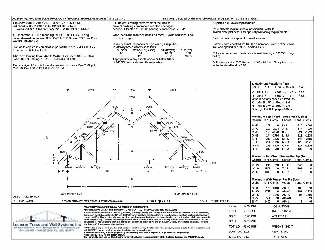
Job:(93049) / -MCBAIN BLDG PRODUCTS /THOMAS SHARLENE BORKE / AT1 29' Attic This dwg. prepared by the ITW job designer program from truss mfr's layout.
PLT TYP. WAVEDESC = AT1 29' Attic
DESIGN CRIT=IBC 2015 /TPI-2014 FT/RT=3%(0%)/0(0) PLY= 1 QTY= 19 REV. 15.02.00C.1217.15
V - Y 1395 0Y - Z 8 - 102F - Z 1 - 10Z -AA 8 - 102G -AA 95 - 1653AA-AB 101 - 1729H -AB 468 - 73I -AB 74 - 299
AD-AE 8 - 99AE- T 1397 0AE- M 1454 0T - O 554 - 91O - S 0 - 1248S - P 1733 0P - R 157 - 2488
**WARNING** READ AND FOLLOW ALL NOTES ON THIS DRAWING!**IMPORTANT** FURNISH THIS DRAWING TO ALL CONTRACTORS INCLUDING THE INSTALLERSTrusses require extreme care in fabricating, handling, shipping, installing and bracing. Refer to and follow the latest edition of BCSI (BuildingComponent Safety Information, by TPI and SBCA) for safety practices prior to performing these functions. Installers shall provide temporarybracing per BCSI. Unless noted otherwise,top chord shall have properly attached structural sheathing and bottom chord shall have a properlyattached rigid ceiling. Locations shown for permanent lateral restraint of webs shall have bracing installed per BCSI sections B3, B7, or B10,as applicable. Apply plates to each face of truss and position as shown above and on the Joint Details, unless noted otherwise. Refer todrawings 160A-Z for standard plate positions.
ITW Building Components Group Inc. shall not be responsible for any deviation from this drawing,any failure to build the truss in conformancewith ANSI/TPI 1, or for handling, shipping, installation and bracing of trusses.A seal on this drawing or cover page listing this drawing, indicates acceptance of professional engineeringresponsibility solely for the design shown.The suitability and use of this drawing for any structure is the responsibility of the Building Designer per ANSI/TPI 1 Sec.2.
TC LL 40.00 PSF
TC DL 7.00 PSF
BC DL 10.00 PSF
BC LL 0.00 PSF
TOT. LD 57.00 PSF
DUR. FAC 1.15
SPACING 24.0 "
JOB #: 93049DATE - 11/28/16
AT1 29' Attic
WEIGHT =363.7
SEQ - 37760
TYPE ATIC

Job:(93049) / -MCBAIN BLDG PRODUCTS /THOMAS SHARLENE BORKE / S1 29' Scissor This dwg. prepared by the ITW job designer program from truss mfr's layout.Top chord 2x4 SP 2850f-2.3EBot chord 2x4 SP 2850f-2.3E Webs 2x4 SPF Stud :W9, W13 2x4 SPF #1/#2:
All plates are 3X5 except as noted. 115 mph wind, 15.00 ft mean hgt, ASCE 7-10, CLOSED bldg,Located anywhere in roof, RISK CAT II, EXP B, wind TC DL=4.2 psf,wind BC DL=6.0 psf.Wind loads and reactions based on MWFRS with additional C&C
member design.End verticals not exposed to wind pressure. Calculated horizontal deflection is 0.61" due to live load and 0.32"
due to dead load.In lieu of structural panels or rigid ceiling use purlinsto laterally brace chords as follows: CHORD SPACING(IN OC) START(FT) END(FT) TC 24 10.65 18.35 BC 75 0.24 10.32 BC 100 10.32 18.68 BC 75 18.68 28.76Apply purlins to any chords above or below fillersat 24" OC unless shown otherwise above.
Bottom chord checked for 10.00 psf non-concurrent bottom chordlive load applied per IBC-15 section 1607. Trusses to be spaced at 16.0" OC maximum.
Deflection meets L/360 live and L/240 total load. Creep increasefactor for dead load is 2.00.
Truss designed for balanced snow load based on Pg=50.00 psf,Ct=1.10, Ce=1.00, CAT II & Pf=38.50 psf.
PLT TYP. WAVEDESC = S1 29' Scissor
DESIGN CRIT=IBC 2015 /TPI-2014 FT/RT=3%(0%)/0(0) PLY= 1 QTY= 12 REV. 15.02.00C.1217.15
Maximum Reactions (lbs)Loc R / U / Rw / Rh / RL / W
X 1338 / - / 480 / - / 143 / 5.5N 1338 / - / 480 / - / - / 5.5Wind reactions based on MWFRSX Min Brg Width Req = 1.5N Min Brg Width Req = 1.5Bearings X & N Fcperp = 565psi.
Maximum Top Chord Forces Per Ply (lbs)Chords Tens.Comp.
A - B 94 0B - C 35 - 1517C - D 0 - 2780D - E 0 - 3750E - F 0 - 4385F - G 0 - 3146
Chords Tens. Comp.
G - H 0 - 3146H - I 0 - 4385I - J 0 - 3750J - K 0 - 2780K - L 29 - 1517L - M 94 0
Maximum Bot Chord Forces Per Ply (lbs)Chords Tens.Comp.
X - W 151 - 242W - V 1489 - 113V - U 2788 - 33U - T 3724 0T - S 2886 0
Chords Tens. Comp.
S - R 2886 0R - Q 3724 0Q - P 2788 0P - O 1489 0O - N 26 - 204
Maximum Web Forces Per Ply (lbs)Webs Tens.Comp.
B - X 95 - 1196B - W 1188 0W - C 0 - 1020C - V 923 0V - D 0 - 852
Webs Tens. Comp.
S - H 314 - 46H - R 2538 0R - I 462 - 32I - Q 0 - 597Q - J 670 0
**WARNING** READ AND FOLLOW ALL NOTES ON THIS DRAWING!**IMPORTANT** FURNISH THIS DRAWING TO ALL CONTRACTORS INCLUDING THE INSTALLERSTrusses require extreme care in fabricating, handling, shipping, installing and bracing. Refer to and follow the latest edition of BCSI (BuildingComponent Safety Information, by TPI and SBCA) for safety practices prior to performing these functions. Installers shall provide temporarybracing per BCSI. Unless noted otherwise,top chord shall have properly attached structural sheathing and bottom chord shall have a properlyattached rigid ceiling. Locations shown for permanent lateral restraint of webs shall have bracing installed per BCSI sections B3, B7, or B10,as applicable. Apply plates to each face of truss and position as shown above and on the Joint Details, unless noted otherwise. Refer todrawings 160A-Z for standard plate positions.
ITW Building Components Group Inc. shall not be responsible for any deviation from this drawing,any failure to build the truss in conformancewith ANSI/TPI 1, or for handling, shipping, installation and bracing of trusses.A seal on this drawing or cover page listing this drawing, indicates acceptance of professional engineeringresponsibility solely for the design shown.The suitability and use of this drawing for any structure is the responsibility of the Building Designer per ANSI/TPI 1 Sec.2.
TC LL 40.00 PSF
TC DL 7.00 PSF
BC DL 10.00 PSF
BC LL 0.00 PSF
TOT. LD 57.00 PSF
DUR. FAC 1.15
SPACING 16.0 "
JOB #: 93049DATE - 11/28/16
S1 29' Scissor
WEIGHT =203.2
SEQ - 37764
TYPE SCIS
17'0"15
7'9"13
17'0"15
13'5"8
8'2"15
13'5"8
10'7"1 7'9"13 10'7"1
10'4"9 8'2"15 10'4"92' 2'
29'
2'3"
8
9'1"
2
12'
8'1"2
LEFT RAKE = 2'8"9 RIGHT RAKE = 2'8"9
A
B
C
D
E
F G H
I
J
K
L
M
N
O
P
Q
RST
U
V
W
X
11
12
1112
3X6
1.5X4
5X5
3X4
3X4
6X8
6X81.5X3
3X8
6X8
6X8
3X4
3X4
5X5
1.5X4
3X6
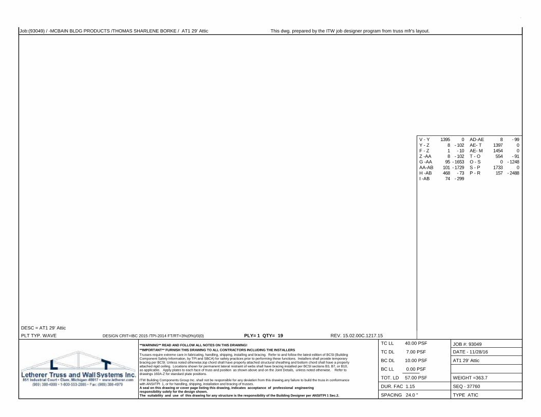
Job:(93049) / -MCBAIN BLDG PRODUCTS /THOMAS SHARLENE BORKE / S1 29' Scissor This dwg. prepared by the ITW job designer program from truss mfr's layout.
PLT TYP. WAVEDESC = S1 29' Scissor
DESIGN CRIT=IBC 2015 /TPI-2014 FT/RT=3%(0%)/0(0) PLY= 1 QTY= 12 REV. 15.02.00C.1217.15
D - U 670 0U - E 0 - 597E - T 462 0T - F 2538 0F - S 314 - 41G - S 60 - 263
J - P 0 - 852P - K 923 0K - O 0 - 1020O - L 1188 0N - L 79 - 1196
**WARNING** READ AND FOLLOW ALL NOTES ON THIS DRAWING!**IMPORTANT** FURNISH THIS DRAWING TO ALL CONTRACTORS INCLUDING THE INSTALLERSTrusses require extreme care in fabricating, handling, shipping, installing and bracing. Refer to and follow the latest edition of BCSI (BuildingComponent Safety Information, by TPI and SBCA) for safety practices prior to performing these functions. Installers shall provide temporarybracing per BCSI. Unless noted otherwise,top chord shall have properly attached structural sheathing and bottom chord shall have a properlyattached rigid ceiling. Locations shown for permanent lateral restraint of webs shall have bracing installed per BCSI sections B3, B7, or B10,as applicable. Apply plates to each face of truss and position as shown above and on the Joint Details, unless noted otherwise. Refer todrawings 160A-Z for standard plate positions.
ITW Building Components Group Inc. shall not be responsible for any deviation from this drawing,any failure to build the truss in conformancewith ANSI/TPI 1, or for handling, shipping, installation and bracing of trusses.A seal on this drawing or cover page listing this drawing, indicates acceptance of professional engineeringresponsibility solely for the design shown.The suitability and use of this drawing for any structure is the responsibility of the Building Designer per ANSI/TPI 1 Sec.2.
TC LL 40.00 PSF
TC DL 7.00 PSF
BC DL 10.00 PSF
BC LL 0.00 PSF
TOT. LD 57.00 PSF
DUR. FAC 1.15
SPACING 16.0 "
JOB #: 93049DATE - 11/28/16
S1 29' Scissor
WEIGHT =203.2
SEQ - 37764
TYPE SCIS
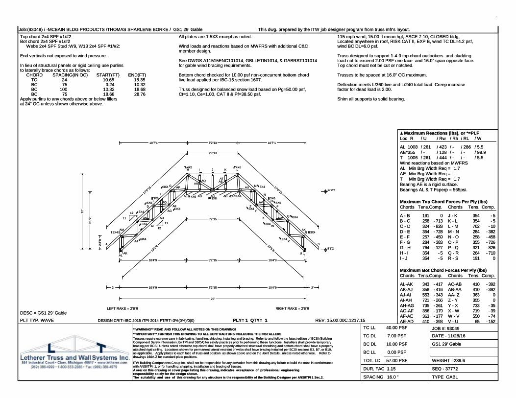
Job:(93049) / -MCBAIN BLDG PRODUCTS /THOMAS SHARLENE BORKE / GS1 29' Gable This dwg. prepared by the ITW job designer program from truss mfr's layout.Top chord 2x4 SPF #1/#2Bot chord 2x4 SPF #1/#2 Webs 2x4 SPF Stud :W9, W13 2x4 SPF #1/#2:
All plates are 1.5X3 except as noted. 115 mph wind, 15.00 ft mean hgt, ASCE 7-10, CLOSED bldg,Located anywhere in roof, RISK CAT II, EXP B, wind TC DL=4.2 psf,wind BC DL=6.0 psf.Wind loads and reactions based on MWFRS with additional C&C
member design.End verticals not exposed to wind pressure. Truss designed to support 1-4-0 top chord outlookers and cladding
load not to exceed 2.00 PSF one face and 16.0" span opposite face.Top chord must not be cut or notched.
See DWGS A11515ENC101014, GBLLETIN1014, & GABRST101014for gable wind bracing requirements.In lieu of structural panels or rigid ceiling use purlins
to laterally brace chords as follows: CHORD SPACING(IN OC) START(FT) END(FT) TC 24 10.65 18.35 BC 75 0.24 10.32 BC 100 10.32 18.68 BC 75 18.68 28.76Apply purlins to any chords above or below fillersat 24" OC unless shown otherwise above.
Bottom chord checked for 10.00 psf non-concurrent bottom chordlive load applied per IBC-15 section 1607.
Trusses to be spaced at 16.0" OC maximum.
Deflection meets L/360 live and L/240 total load. Creep increasefactor for dead load is 2.00.Truss designed for balanced snow load based on Pg=50.00 psf,
Ct=1.10, Ce=1.00, CAT II & Pf=38.50 psf.Shim all supports to solid bearing.
PLT TYP. WAVEDESC = GS1 29' Gable
DESIGN CRIT=IBC 2015 /TPI-2014 FT/RT=3%(0%)/0(0) PLY= 1 QTY= 1 REV. 15.02.00C.1217.15
Maximum Reactions (lbs), or *=PLFLoc R / U / Rw / Rh / RL / W
AL 1008 / 261 / 423 / - / 286 / 5.5AE*355 / - / 128 / - / - / 98.9T 1006 / 261 / 444 / - / - / 5.5Wind reactions based on MWFRSAL Min Brg Width Req = 1.7AE Min Brg Width Req = -T Min Brg Width Req = 1.7Bearing AE is a rigid surface.Bearings AL & T Fcperp = 565psi.
Maximum Top Chord Forces Per Ply (lbs)Chords Tens.Comp.
A - B 191 0B - C 258 - 713C - D 324 - 828D - E 354 - 728E - F 257 - 459F - G 284 - 383G - H 764 - 127H - I 354 - 5I - J 354 - 5
Chords Tens. Comp.
J - K 354 - 5K - L 354 - 5L - M 762 - 10M - N 284 - 382N - O 258 - 458O - P 355 - 726P - Q 321 - 826Q - R 264 - 710R - S 191 0
Maximum Bot Chord Forces Per Ply (lbs)Chords Tens.Comp.
AL-AK 343 - 417AK-AJ 358 - 416AJ-AI 553 - 343AI-AH 721 - 266AH-AG 735 - 261AG-AF 356 - 179AF-AE 363 - 177AE-AD 410 - 393
Chords Tens. Comp.
AC-AB 410 - 392AB-AA 410 - 392AA- Z 363 0Z - Y 355 0Y - X 733 - 35X - W 719 - 39W - V 550 - 74V - U 65 - 152
**WARNING** READ AND FOLLOW ALL NOTES ON THIS DRAWING!**IMPORTANT** FURNISH THIS DRAWING TO ALL CONTRACTORS INCLUDING THE INSTALLERSTrusses require extreme care in fabricating, handling, shipping, installing and bracing. Refer to and follow the latest edition of BCSI (BuildingComponent Safety Information, by TPI and SBCA) for safety practices prior to performing these functions. Installers shall provide temporarybracing per BCSI. Unless noted otherwise,top chord shall have properly attached structural sheathing and bottom chord shall have a properlyattached rigid ceiling. Locations shown for permanent lateral restraint of webs shall have bracing installed per BCSI sections B3, B7, or B10,as applicable. Apply plates to each face of truss and position as shown above and on the Joint Details, unless noted otherwise. Refer todrawings 160A-Z for standard plate positions.
ITW Building Components Group Inc. shall not be responsible for any deviation from this drawing,any failure to build the truss in conformancewith ANSI/TPI 1, or for handling, shipping, installation and bracing of trusses.A seal on this drawing or cover page listing this drawing, indicates acceptance of professional engineeringresponsibility solely for the design shown.The suitability and use of this drawing for any structure is the responsibility of the Building Designer per ANSI/TPI 1 Sec.2.
TC LL 40.00 PSF
TC DL 7.00 PSF
BC DL 10.00 PSF
BC LL 0.00 PSF
TOT. LD 57.00 PSF
DUR. FAC 1.15
SPACING 16.0 "
JOB #: 93049DATE - 11/28/16
GS1 29' Gable
WEIGHT =239.6
SEQ - 37772
TYPE GABL
10'4"9 8'2"15 10'4"9
17'0"15
7'9"13
17'0"15
13'5"8
8'2"15
13'5"8
10'7"1 7'9"13 10'7"1
10'4"9 8'2"15 10'4"92' 2'
29'
2'3"
8
9'1"
2
12'
8'1"2
17'2"4
LEFT RAKE = 2'8"9 RIGHT RAKE = 2'8"9
A
B
C
D
E
F
G
H I J K L
M
N
O
P
Q
R
S
TU
V
W
X
YZ
AAABACADAE
AFAG
AH
AI
AJ
AKAL
AM
AN
AO
AP
AQAR
ASAT
AU
AV
AW
AX
11
12
1112
3X4
3X4
3X4
3X4
5X53X6
3X4
3X4
4X6
4X6
3X8
4X6
4X6
3X4
3X4
3X65X5
3X4
3X4
3X4
3X4

Job:(93049) / -MCBAIN BLDG PRODUCTS /THOMAS SHARLENE BORKE / GS1 29' Gable This dwg. prepared by the ITW job designer program from truss mfr's layout.
PLT TYP. WAVEDESC = GS1 29' Gable
DESIGN CRIT=IBC 2015 /TPI-2014 FT/RT=3%(0%)/0(0) PLY= 1 QTY= 1 REV. 15.02.00C.1217.15
AD-AC 410 - 393 U - T 60 - 172
Maximum Web Forces Per Ply (lbs)Webs Tens.Comp.
B -AL 299 - 879B -AM 495 - 77AM-AJ 495 - 77AJ- C 102 - 424C -AN 139 - 5AN-AI 130 - 6AI- E 63 - 35E -AO 133 - 259AO-AG 134 - 263AG- G 290 - 113G -AP 279 - 744AP-AE 279 - 744AE- H 107 - 737H -AQ 85 - 54AR-AC 86 - 54J -AC 60 - 279
Webs Tens. Comp.
AC-AS 85 - 39AT- L 85 - 39L -AA 37 - 735AA-AU 279 - 742AU- M 280 - 742M - Y 289 - 113Y -AV 133 - 262AV- O 132 - 258O - W 49 - 29W -AW 130 0AW- Q 139 0Q - V 99 - 422V -AX 494 - 74AX- R 493 - 74T - R 300 - 877
Maximum Gable Forces Per Ply (lbs)Gables Tens.Comp.
AM-AK 16 - 28D -AN 41 - 94F -AO 20 - 45AO-AH 19 - 11AP-AF 20 0AQ- I 63 - 307AD-AR 63 - 309
Gables Tens. Comp.
AS-AB 63 - 308K -AT 63 - 307Z -AU 20 0X -AV 19 - 11AV- N 20 - 45AW- P 40 - 94U -AX 16 - 28
**WARNING** READ AND FOLLOW ALL NOTES ON THIS DRAWING!**IMPORTANT** FURNISH THIS DRAWING TO ALL CONTRACTORS INCLUDING THE INSTALLERSTrusses require extreme care in fabricating, handling, shipping, installing and bracing. Refer to and follow the latest edition of BCSI (BuildingComponent Safety Information, by TPI and SBCA) for safety practices prior to performing these functions. Installers shall provide temporarybracing per BCSI. Unless noted otherwise,top chord shall have properly attached structural sheathing and bottom chord shall have a properlyattached rigid ceiling. Locations shown for permanent lateral restraint of webs shall have bracing installed per BCSI sections B3, B7, or B10,as applicable. Apply plates to each face of truss and position as shown above and on the Joint Details, unless noted otherwise. Refer todrawings 160A-Z for standard plate positions.
ITW Building Components Group Inc. shall not be responsible for any deviation from this drawing,any failure to build the truss in conformancewith ANSI/TPI 1, or for handling, shipping, installation and bracing of trusses.A seal on this drawing or cover page listing this drawing, indicates acceptance of professional engineeringresponsibility solely for the design shown.The suitability and use of this drawing for any structure is the responsibility of the Building Designer per ANSI/TPI 1 Sec.2.
TC LL 40.00 PSF
TC DL 7.00 PSF
BC DL 10.00 PSF
BC LL 0.00 PSF
TOT. LD 57.00 PSF
DUR. FAC 1.15
SPACING 16.0 "
JOB #: 93049DATE - 11/28/16
GS1 29' Gable
WEIGHT =239.6
SEQ - 37772
TYPE GABL
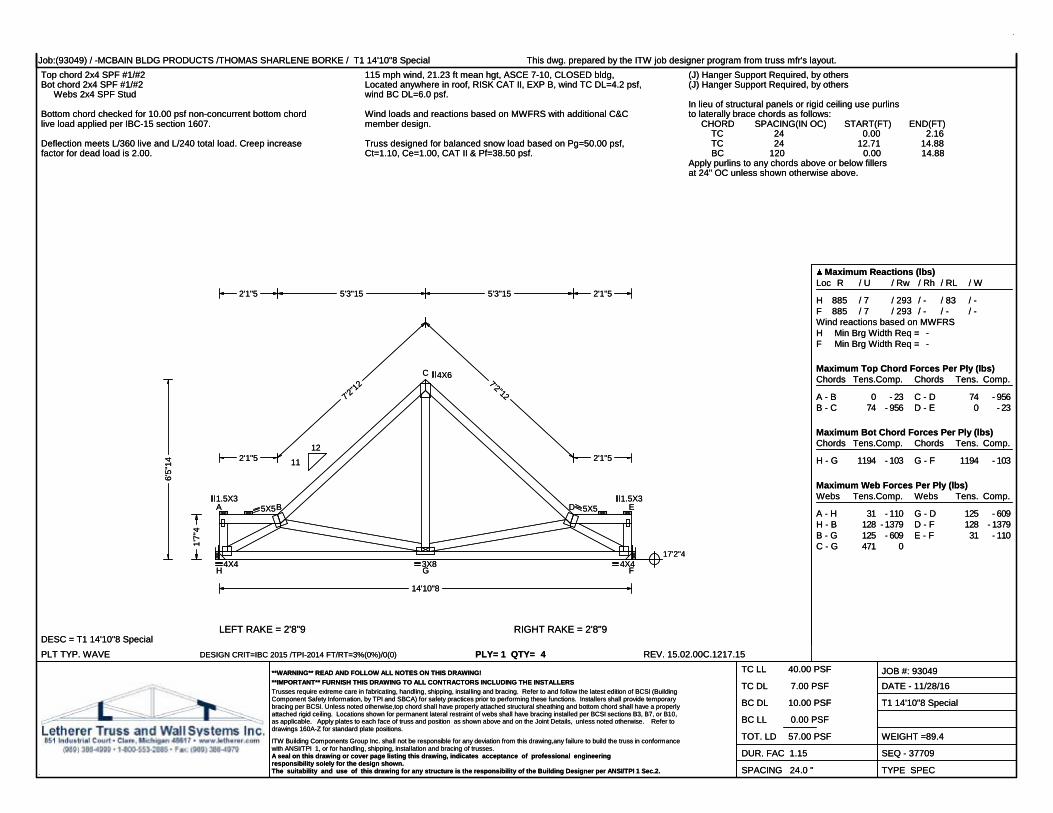
Job:(93049) / -MCBAIN BLDG PRODUCTS /THOMAS SHARLENE BORKE / T1 14'10"8 Special This dwg. prepared by the ITW job designer program from truss mfr's layout.Top chord 2x4 SPF #1/#2Bot chord 2x4 SPF #1/#2 Webs 2x4 SPF Stud
115 mph wind, 21.23 ft mean hgt, ASCE 7-10, CLOSED bldg,Located anywhere in roof, RISK CAT II, EXP B, wind TC DL=4.2 psf,wind BC DL=6.0 psf.
Wind loads and reactions based on MWFRS with additional C&Cmember design.
(J) Hanger Support Required, by others(J) Hanger Support Required, by others
In lieu of structural panels or rigid ceiling use purlinsto laterally brace chords as follows: CHORD SPACING(IN OC) START(FT) END(FT) TC 24 0.00 2.16 TC 24 12.71 14.88 BC 120 0.00 14.88Apply purlins to any chords above or below fillersat 24" OC unless shown otherwise above.
Bottom chord checked for 10.00 psf non-concurrent bottom chordlive load applied per IBC-15 section 1607.
Deflection meets L/360 live and L/240 total load. Creep increasefactor for dead load is 2.00.
Truss designed for balanced snow load based on Pg=50.00 psf,Ct=1.10, Ce=1.00, CAT II & Pf=38.50 psf.
PLT TYP. WAVEDESC = T1 14'10"8 Special
DESIGN CRIT=IBC 2015 /TPI-2014 FT/RT=3%(0%)/0(0) PLY= 1 QTY= 4 REV. 15.02.00C.1217.15
Maximum Reactions (lbs)Loc R / U / Rw / Rh / RL / W
H 885 / 7 / 293 / - / 83 / -F 885 / 7 / 293 / - / - / -Wind reactions based on MWFRSH Min Brg Width Req = -F Min Brg Width Req = -
Maximum Top Chord Forces Per Ply (lbs)Chords Tens.Comp.
A - B 0 - 23B - C 74 - 956
Chords Tens. Comp.
C - D 74 - 956D - E 0 - 23
Maximum Bot Chord Forces Per Ply (lbs)Chords Tens.Comp.
H - G 1194 - 103
Chords Tens. Comp.
G - F 1194 - 103
Maximum Web Forces Per Ply (lbs)Webs Tens.Comp.
A - H 31 - 110H - B 128 - 1379B - G 125 - 609C - G 471 0
Webs Tens. Comp.
G - D 125 - 609D - F 128 - 1379E - F 31 - 110
**WARNING** READ AND FOLLOW ALL NOTES ON THIS DRAWING!**IMPORTANT** FURNISH THIS DRAWING TO ALL CONTRACTORS INCLUDING THE INSTALLERSTrusses require extreme care in fabricating, handling, shipping, installing and bracing. Refer to and follow the latest edition of BCSI (BuildingComponent Safety Information, by TPI and SBCA) for safety practices prior to performing these functions. Installers shall provide temporarybracing per BCSI. Unless noted otherwise,top chord shall have properly attached structural sheathing and bottom chord shall have a properlyattached rigid ceiling. Locations shown for permanent lateral restraint of webs shall have bracing installed per BCSI sections B3, B7, or B10,as applicable. Apply plates to each face of truss and position as shown above and on the Joint Details, unless noted otherwise. Refer todrawings 160A-Z for standard plate positions.
ITW Building Components Group Inc. shall not be responsible for any deviation from this drawing,any failure to build the truss in conformancewith ANSI/TPI 1, or for handling, shipping, installation and bracing of trusses.A seal on this drawing or cover page listing this drawing, indicates acceptance of professional engineeringresponsibility solely for the design shown.The suitability and use of this drawing for any structure is the responsibility of the Building Designer per ANSI/TPI 1 Sec.2.
TC LL 40.00 PSF
TC DL 7.00 PSF
BC DL 10.00 PSF
BC LL 0.00 PSF
TOT. LD 57.00 PSF
DUR. FAC 1.15
SPACING 24.0 "
JOB #: 93049DATE - 11/28/16
T1 14'10"8 Special
WEIGHT =89.4
SEQ - 37709
TYPE SPEC
2'1"5
7'2"12 7'2"12
2'1"5
2'1"5 5'3"15 5'3"15 2'1"5
14'10"8
1'7"
4
6'5"
14
17'2"4
LEFT RAKE = 2'8"9 RIGHT RAKE = 2'8"9
A B
C
D E
FGH
11
12
1.5X3
4X4
5X5
4X6
3X8
5X51.5X3
4X4

Job:(93049) / -MCBAIN BLDG PRODUCTS /THOMAS SHARLENE BORKE / T2 8' Common This dwg. prepared by the ITW job designer program from truss mfr's layout.Top chord 2x4 SPF #1/#2Bot chord 2x4 SPF #1/#2 Webs 2x4 SPF Stud
115 mph wind, 19.35 ft mean hgt, ASCE 7-10, CLOSED bldg,Located anywhere in roof, RISK CAT II, EXP B, wind TC DL=4.2 psf,wind BC DL=6.0 psf.
Wind loads and reactions based on MWFRS with additional C&Cmember design.
In lieu of structural panels or rigid ceiling use purlinsto laterally brace chords as follows: CHORD SPACING(IN OC) START(FT) END(FT) BC 96 0.00 8.00Apply purlins to any chords above or below fillersat 24" OC unless shown otherwise above.
Bottom chord checked for 10.00 psf non-concurrent bottom chordlive load applied per IBC-15 section 1607.
Deflection meets L/360 live and L/240 total load. Creep increasefactor for dead load is 2.00.
Truss designed for balanced snow load based on Pg=50.00 psf,Ct=1.10, Ce=1.00, CAT II & Pf=38.50 psf.
PLT TYP. WAVEDESC = T2 8' Common
DESIGN CRIT=IBC 2015 /TPI-2014 FT/RT=3%(0%)/0(0) PLY= 1 QTY= 6 REV. 15.02.00C.1217.15
Maximum Reactions (lbs)Loc R / U / Rw / Rh / RL / W
H 607 / 8 / 207 / - / 79 / 3.5F 607 / 8 / 207 / - / - / 3.5Wind reactions based on MWFRSH Min Brg Width Req = 1.5F Min Brg Width Req = 1.5Bearings H & F Fcperp = 565psi.
Maximum Top Chord Forces Per Ply (lbs)Chords Tens.Comp.
A - B 82 0B - C 56 - 439
Chords Tens. Comp.
C - D 56 - 439D - E 82 0
Maximum Bot Chord Forces Per Ply (lbs)Chords Tens.Comp.
H - G 83 - 79
Chords Tens. Comp.
G - F 13 - 2
Maximum Web Forces Per Ply (lbs)Webs Tens.Comp.
B - H 103 - 574B - G 253 - 2C - G 139 - 10
Webs Tens. Comp.
G - D 253 - 3D - F 102 - 574
**WARNING** READ AND FOLLOW ALL NOTES ON THIS DRAWING!**IMPORTANT** FURNISH THIS DRAWING TO ALL CONTRACTORS INCLUDING THE INSTALLERSTrusses require extreme care in fabricating, handling, shipping, installing and bracing. Refer to and follow the latest edition of BCSI (BuildingComponent Safety Information, by TPI and SBCA) for safety practices prior to performing these functions. Installers shall provide temporarybracing per BCSI. Unless noted otherwise,top chord shall have properly attached structural sheathing and bottom chord shall have a properlyattached rigid ceiling. Locations shown for permanent lateral restraint of webs shall have bracing installed per BCSI sections B3, B7, or B10,as applicable. Apply plates to each face of truss and position as shown above and on the Joint Details, unless noted otherwise. Refer todrawings 160A-Z for standard plate positions.
ITW Building Components Group Inc. shall not be responsible for any deviation from this drawing,any failure to build the truss in conformancewith ANSI/TPI 1, or for handling, shipping, installation and bracing of trusses.A seal on this drawing or cover page listing this drawing, indicates acceptance of professional engineeringresponsibility solely for the design shown.The suitability and use of this drawing for any structure is the responsibility of the Building Designer per ANSI/TPI 1 Sec.2.
TC LL 40.00 PSF
TC DL 7.00 PSF
BC DL 10.00 PSF
BC LL 0.00 PSF
TOT. LD 57.00 PSF
DUR. FAC 1.15
SPACING 24.0 "
JOB #: 93049DATE - 11/28/16
T2 8' Common
WEIGHT =49.7
SEQ - 37685
TYPE COMN
6'8" 6'8"
4' 4'
8'1'4" 1'4"
1'2"
4'2"
4'4"
6
17'2"4
LEFT RAKE = 1'8" RIGHT RAKE = 1'8"
A
B
C
D
E
FGH
912
3X4
1.5X4
4X4
3X8
3X4
1.5X4

Job:(93049) / -MCBAIN BLDG PRODUCTS /THOMAS SHARLENE BORKE / TG1 8' Special Girder This dwg. prepared by the ITW job designer program from truss mfr's layout.Top chord 2x4 SPF #1/#2Bot chord 2x6 SP 2700f-2.0E Webs 2x4 SPF Stud
Special loads------(Lumber Dur.Fac.=1.15 / Plate Dur.Fac.=1.15) TC- From 98 plf at -1.33 to 98 plf at 0.85 TC- From 49 plf at 0.85 to 49 plf at 4.00 TC- From 49 plf at 4.00 to 49 plf at 6.85 TC- From 98 plf at 6.85 to 98 plf at 9.33 BC- From 5 plf at -1.33 to 5 plf at 0.00 BC- From 10 plf at 0.00 to 10 plf at 8.00 BC- From 5 plf at 8.00 to 5 plf at 9.33 BC- 885.00 lb Conc. Load at 0.85, 2.85, 4.85, 6.85
115 mph wind, 19.35 ft mean hgt, ASCE 7-10, CLOSED bldg,Located anywhere in roof, RISK CAT II, EXP B, wind TC DL=4.2 psf,wind BC DL=6.0 psf.
Wind loads and reactions based on MWFRS. In lieu of structural panels or rigid ceiling use purlinsto laterally brace chords as follows: CHORD SPACING(IN OC) START(FT) END(FT) BC 96 0.00 8.00Apply purlins to any chords above or below fillersat 24" OC unless shown otherwise above.
Bottom chord checked for 10.00 psf non-concurrent bottom chordlive load applied per IBC-15 section 1607.
Deflection meets L/360 live and L/240 total load. Creep increasefactor for dead load is 2.00.
Truss designed for balanced snow load based on Pg=50.00 psf,Ct=1.10, Ce=1.00, CAT II & Pf=38.50 psf.
PLT TYP. WAVEDESC = TG1 8' Special Girder
DESIGN CRIT=IBC 2015 /TPI-2014 FT/RT=3%(0%)/0(0) PLY= 1 QTY= 2 REV. 15.02.00C.1217.15
Maximum Reactions (lbs)Loc R / U / Rw / Rh / RL / W
H 2250 / 43 / - / - / - / 3.5F 2131 / 44 / - / - / - / 3.5Wind reactions based on MWFRSH Min Brg Width Req = 2.1F Min Brg Width Req = 2.0Bearings H & F Fcperp = 565psi.
Maximum Top Chord Forces Per Ply (lbs)Chords Tens.Comp.
A - B 82 - 11B - C 22 - 1672
Chords Tens. Comp.
C - D 23 - 1679D - E 82 - 11
Maximum Bot Chord Forces Per Ply (lbs)Chords Tens.Comp.
H - G 31 0
Chords Tens. Comp.
G - F 33 0
Maximum Web Forces Per Ply (lbs)Webs Tens.Comp.
B - H 46 - 1467B - G 1257 - 8C - G 1718 - 7
Webs Tens. Comp.
G - D 1256 - 8D - F 48 - 1478
**WARNING** READ AND FOLLOW ALL NOTES ON THIS DRAWING!**IMPORTANT** FURNISH THIS DRAWING TO ALL CONTRACTORS INCLUDING THE INSTALLERSTrusses require extreme care in fabricating, handling, shipping, installing and bracing. Refer to and follow the latest edition of BCSI (BuildingComponent Safety Information, by TPI and SBCA) for safety practices prior to performing these functions. Installers shall provide temporarybracing per BCSI. Unless noted otherwise,top chord shall have properly attached structural sheathing and bottom chord shall have a properlyattached rigid ceiling. Locations shown for permanent lateral restraint of webs shall have bracing installed per BCSI sections B3, B7, or B10,as applicable. Apply plates to each face of truss and position as shown above and on the Joint Details, unless noted otherwise. Refer todrawings 160A-Z for standard plate positions.
ITW Building Components Group Inc. shall not be responsible for any deviation from this drawing,any failure to build the truss in conformancewith ANSI/TPI 1, or for handling, shipping, installation and bracing of trusses.A seal on this drawing or cover page listing this drawing, indicates acceptance of professional engineeringresponsibility solely for the design shown.The suitability and use of this drawing for any structure is the responsibility of the Building Designer per ANSI/TPI 1 Sec.2.
TC LL 40.00 PSF
TC DL 7.00 PSF
BC DL 10.00 PSF
BC LL 0.00 PSF
TOT. LD 57.00 PSF
DUR. FAC 1.15
SPACING 24.0 "
JOB #: 93049DATE - 11/28/16
TG1 8' Special Girder
WEIGHT =54.7
SEQ - 37712
TYPE SPEC
6'8" 6'8"
4' 4'
8'1'4" 1'4"
1'2"
4'2"
4'4"
6
17'2"4
LEFT RAKE = 1'8" RIGHT RAKE = 1'8"
A
B
C
D
E
FGH
912
3X8
2X6
4X6
7X8
3X8
2X6

Job:(93049) / -MCBAIN BLDG PRODUCTS /THOMAS SHARLENE BORKE / G2 8' Gable This dwg. prepared by the ITW job designer program from truss mfr's layout.Top chord 2x4 SPF #1/#2Bot chord 2x4 SPF #1/#2 Webs 2x4 SPF Stud
All plates are 1.5X3 except as noted. 115 mph wind, 19.35 ft mean hgt, ASCE 7-10, CLOSED bldg,Located anywhere in roof, RISK CAT II, EXP B, wind TC DL=4.2 psf,wind BC DL=6.0 psf.Wind loads and reactions based on MWFRS with additional C&C
member design.The studded portion of the truss is designed to support 1-4-0 topchord outlookers and 2.00 PSF cladding load one face, and 24.0"span on opposite face. Top chord must not be cut or notched.Vertical and roof plane diaphragms, and connections by others.
See DWGS A11530ENC101014, GBLLETIN1014, & GABRST101014for gable wind bracing requirements.In lieu of structural panels or rigid ceiling use purlins
to laterally brace chords as follows: CHORD SPACING(IN OC) START(FT) END(FT) BC 96 0.00 8.00Apply purlins to any chords above or below fillersat 24" OC unless shown otherwise above.
Bottom chord checked for 10.00 psf non-concurrent bottom chordlive load applied per IBC-15 section 1607.
Deflection meets L/360 live and L/240 total load. Creep increasefactor for dead load is 2.00. Truss designed for balanced snow load based on Pg=50.00 psf,
Ct=1.10, Ce=1.00, CAT II & Pf=38.50 psf.Fasten rated sheathing to one face of this frame.
PLT TYP. WAVEDESC = G2 8' Gable
DESIGN CRIT=IBC 2015 /TPI-2014 FT/RT=3%(0%)/0(0) PLY= 1 QTY= 2 REV. 15.02.00C.1217.15
Maximum Reactions (lbs), or *=PLFLoc R / U / Rw / Rh / RL / W
L* 166 / 22 / 44 / - / 14 / 96.0H 383 / 177 / 101 / - / - / 3.5Wind reactions based on MWFRSL Min Brg Width Req = -H Min Brg Width Req = 1.5Bearings L & H Fcperp = 565psi.
Maximum Top Chord Forces Per Ply (lbs)Chords Tens.Comp.
A - B 116 0B - C 123 - 99C - D 210 - 84
Chords Tens. Comp.
D - E 210 - 84E - F 123 - 99F - G 116 0
Maximum Bot Chord Forces Per Ply (lbs)Chords Tens.Comp.
L - K 55 - 57K - J 53 - 57
Chords Tens. Comp.
J - I 53 - 57I - H 51 - 54
Maximum Web Forces Per Ply (lbs)Webs Tens.Comp.
B - L 187 - 366
Webs Tens. Comp.
F - H 187 - 366
Maximum Gable Forces Per Ply (lbs)Gables Tens.Comp.
C - K 121 - 264J - D 0 - 288
Gables Tens. Comp.
I - E 121 - 264
**WARNING** READ AND FOLLOW ALL NOTES ON THIS DRAWING!**IMPORTANT** FURNISH THIS DRAWING TO ALL CONTRACTORS INCLUDING THE INSTALLERSTrusses require extreme care in fabricating, handling, shipping, installing and bracing. Refer to and follow the latest edition of BCSI (BuildingComponent Safety Information, by TPI and SBCA) for safety practices prior to performing these functions. Installers shall provide temporarybracing per BCSI. Unless noted otherwise,top chord shall have properly attached structural sheathing and bottom chord shall have a properlyattached rigid ceiling. Locations shown for permanent lateral restraint of webs shall have bracing installed per BCSI sections B3, B7, or B10,as applicable. Apply plates to each face of truss and position as shown above and on the Joint Details, unless noted otherwise. Refer todrawings 160A-Z for standard plate positions.
ITW Building Components Group Inc. shall not be responsible for any deviation from this drawing,any failure to build the truss in conformancewith ANSI/TPI 1, or for handling, shipping, installation and bracing of trusses.A seal on this drawing or cover page listing this drawing, indicates acceptance of professional engineeringresponsibility solely for the design shown.The suitability and use of this drawing for any structure is the responsibility of the Building Designer per ANSI/TPI 1 Sec.2.
TC LL 40.00 PSF
TC DL 7.00 PSF
BC DL 10.00 PSF
BC LL 0.00 PSF
TOT. LD 57.00 PSF
DUR. FAC 1.15
SPACING 24.0 "
JOB #: 93049DATE - 11/28/16
G2 8' Gable
WEIGHT =46.9
SEQ - 37688
TYPE GABL
8'
6'8" 6'8"
4' 4'
1'4" 1'4"
1'2"
4'2"
4'4"
6
17'2"4
LEFT RAKE = 1'8" RIGHT RAKE = 1'8"
A
B
C
D
E
F
G
HIJK
L
912
2X6
4X4
2X6
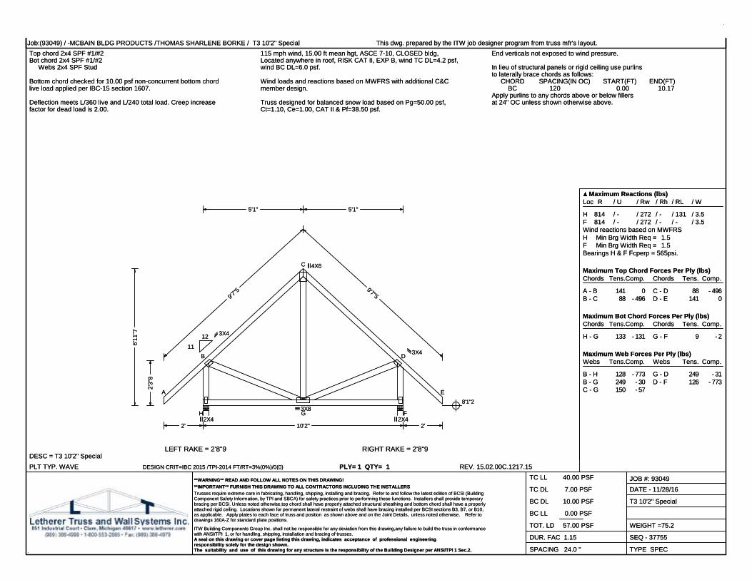
Job:(93049) / -MCBAIN BLDG PRODUCTS /THOMAS SHARLENE BORKE / T3 10'2" Special This dwg. prepared by the ITW job designer program from truss mfr's layout.Top chord 2x4 SPF #1/#2Bot chord 2x4 SPF #1/#2 Webs 2x4 SPF Stud
115 mph wind, 15.00 ft mean hgt, ASCE 7-10, CLOSED bldg,Located anywhere in roof, RISK CAT II, EXP B, wind TC DL=4.2 psf,wind BC DL=6.0 psf.
Wind loads and reactions based on MWFRS with additional C&Cmember design.
End verticals not exposed to wind pressure.
In lieu of structural panels or rigid ceiling use purlinsto laterally brace chords as follows: CHORD SPACING(IN OC) START(FT) END(FT) BC 120 0.00 10.17Apply purlins to any chords above or below fillersat 24" OC unless shown otherwise above.
Bottom chord checked for 10.00 psf non-concurrent bottom chordlive load applied per IBC-15 section 1607.
Deflection meets L/360 live and L/240 total load. Creep increasefactor for dead load is 2.00.
Truss designed for balanced snow load based on Pg=50.00 psf,Ct=1.10, Ce=1.00, CAT II & Pf=38.50 psf.
PLT TYP. WAVEDESC = T3 10'2" Special
DESIGN CRIT=IBC 2015 /TPI-2014 FT/RT=3%(0%)/0(0) PLY= 1 QTY= 1 REV. 15.02.00C.1217.15
Maximum Reactions (lbs)Loc R / U / Rw / Rh / RL / W
H 814 / - / 272 / - / 131 / 3.5F 814 / - / 272 / - / - / 3.5Wind reactions based on MWFRSH Min Brg Width Req = 1.5F Min Brg Width Req = 1.5Bearings H & F Fcperp = 565psi.
Maximum Top Chord Forces Per Ply (lbs)Chords Tens.Comp.
A - B 141 0B - C 88 - 496
Chords Tens. Comp.
C - D 88 - 496D - E 141 0
Maximum Bot Chord Forces Per Ply (lbs)Chords Tens.Comp.
H - G 133 - 131
Chords Tens. Comp.
G - F 9 - 2
Maximum Web Forces Per Ply (lbs)Webs Tens.Comp.
B - H 128 - 773B - G 249 - 30C - G 150 - 57
Webs Tens. Comp.
G - D 249 - 31D - F 126 - 773
**WARNING** READ AND FOLLOW ALL NOTES ON THIS DRAWING!**IMPORTANT** FURNISH THIS DRAWING TO ALL CONTRACTORS INCLUDING THE INSTALLERSTrusses require extreme care in fabricating, handling, shipping, installing and bracing. Refer to and follow the latest edition of BCSI (BuildingComponent Safety Information, by TPI and SBCA) for safety practices prior to performing these functions. Installers shall provide temporarybracing per BCSI. Unless noted otherwise,top chord shall have properly attached structural sheathing and bottom chord shall have a properlyattached rigid ceiling. Locations shown for permanent lateral restraint of webs shall have bracing installed per BCSI sections B3, B7, or B10,as applicable. Apply plates to each face of truss and position as shown above and on the Joint Details, unless noted otherwise. Refer todrawings 160A-Z for standard plate positions.
ITW Building Components Group Inc. shall not be responsible for any deviation from this drawing,any failure to build the truss in conformancewith ANSI/TPI 1, or for handling, shipping, installation and bracing of trusses.A seal on this drawing or cover page listing this drawing, indicates acceptance of professional engineeringresponsibility solely for the design shown.The suitability and use of this drawing for any structure is the responsibility of the Building Designer per ANSI/TPI 1 Sec.2.
TC LL 40.00 PSF
TC DL 7.00 PSF
BC DL 10.00 PSF
BC LL 0.00 PSF
TOT. LD 57.00 PSF
DUR. FAC 1.15
SPACING 24.0 "
JOB #: 93049DATE - 11/28/16
T3 10'2" Special
WEIGHT =75.2
SEQ - 37755
TYPE SPEC
9'7"5 9'7"5
5'1" 5'1"
10'2"2' 2'
2'3"
8
6'11
"7
8'1"2
LEFT RAKE = 2'8"9 RIGHT RAKE = 2'8"9
A
B
C
D
E
FGH
11
12 3X4
2X4
4X6
3X8
3X4
2X4

Job:(93049) / -MCBAIN BLDG PRODUCTS /THOMAS SHARLENE BORKE / G1 10'2" Gable This dwg. prepared by the ITW job designer program from truss mfr's layout.Top chord 2x4 SPF #1/#2Bot chord 2x4 SPF #1/#2 Webs 2x4 SPF Stud
All plates are 1.5X3 except as noted. 115 mph wind, 15.00 ft mean hgt, ASCE 7-10, CLOSED bldg,Located anywhere in roof, RISK CAT II, EXP B, wind TC DL=4.2 psf,wind BC DL=6.0 psf.Wind loads and reactions based on MWFRS with additional C&C
member design.End verticals not exposed to wind pressure. Calculated horizontal deflection is 0.17" due to live load and 0.11"
due to dead load.Truss designed to support 1-4-0 top chord outlookers and claddingload not to exceed 2.00 PSF one face and 24.0" span opposite face.Top chord must not be cut or notched.
See DWGS A11515ENC101014, GBLLETIN1014, & GABRST101014for gable wind bracing requirements. In lieu of structural panels or rigid ceiling use purlins
to laterally brace chords as follows: CHORD SPACING(IN OC) START(FT) END(FT) BC 120 0.00 10.17Apply purlins to any chords above or below fillersat 24" OC unless shown otherwise above.
Bottom chord checked for 10.00 psf non-concurrent bottom chordlive load applied per IBC-15 section 1607.
Deflection meets L/360 live and L/240 total load. Creep increasefactor for dead load is 2.00.
Truss designed for balanced snow load based on Pg=50.00 psf,Ct=1.10, Ce=1.00, CAT II & Pf=38.50 psf.
Fasten rated sheathing to one face of this frame.
PLT TYP. WAVEDESC = G1 10'2" Gable
DESIGN CRIT=IBC 2015 /TPI-2014 FT/RT=3%(0%)/0(0) PLY= 1 QTY= 1 REV. 15.02.00C.1217.15
Maximum Reactions (lbs), or *=PLFLoc R / U / Rw / Rh / RL / W
J* 220 / 32 / 62 / - / 18 / 121Wind reactions based on MWFRSP Min Brg Width Req = -Bearing P Fcperp = 565psi.
Maximum Top Chord Forces Per Ply (lbs)Chords Tens.Comp.
A - B 204 0B - C 257 - 249C - D 253 - 102D - E 360 - 134
Chords Tens. Comp.
E - F 361 - 134F - G 252 - 102G - H 256 - 249H - I 204 0
Maximum Bot Chord Forces Per Ply (lbs)Chords Tens.Comp.
P - O 87 - 84O - N 94 - 89N - M 94 - 90
Chords Tens. Comp.
M - L 94 - 90L - K 95 - 89K - J 98 - 95
Maximum Gable Forces Per Ply (lbs)Gables Tens.Comp.
P - B 353 - 663C - O 222 - 135D - N 148 - 357M - E 10 - 425
Gables Tens. Comp.
L - F 148 - 357K - G 223 - 136H - J 347 - 663
**WARNING** READ AND FOLLOW ALL NOTES ON THIS DRAWING!**IMPORTANT** FURNISH THIS DRAWING TO ALL CONTRACTORS INCLUDING THE INSTALLERSTrusses require extreme care in fabricating, handling, shipping, installing and bracing. Refer to and follow the latest edition of BCSI (BuildingComponent Safety Information, by TPI and SBCA) for safety practices prior to performing these functions. Installers shall provide temporarybracing per BCSI. Unless noted otherwise,top chord shall have properly attached structural sheathing and bottom chord shall have a properlyattached rigid ceiling. Locations shown for permanent lateral restraint of webs shall have bracing installed per BCSI sections B3, B7, or B10,as applicable. Apply plates to each face of truss and position as shown above and on the Joint Details, unless noted otherwise. Refer todrawings 160A-Z for standard plate positions.
ITW Building Components Group Inc. shall not be responsible for any deviation from this drawing,any failure to build the truss in conformancewith ANSI/TPI 1, or for handling, shipping, installation and bracing of trusses.A seal on this drawing or cover page listing this drawing, indicates acceptance of professional engineeringresponsibility solely for the design shown.The suitability and use of this drawing for any structure is the responsibility of the Building Designer per ANSI/TPI 1 Sec.2.
TC LL 40.00 PSF
TC DL 7.00 PSF
BC DL 10.00 PSF
BC LL 0.00 PSF
TOT. LD 57.00 PSF
DUR. FAC 1.15
SPACING 24.0 "
JOB #: 93049DATE - 11/28/16
G1 10'2" Gable
WEIGHT =80.4
SEQ - 37739
TYPE GABL
10'2"
9'7"5 9'7"5
5'1" 5'1"
2' 2'
2'3"
8
6'11
"7
8'1"2
LEFT RAKE = 2'8"9 RIGHT RAKE = 2'8"9
A
B
C
D
E
F
G
H
I
JKLMNO
P
11
12
2X6
1.5X4
4X4
1.5X4
2X6

Job:(93049) / -MCBAIN BLDG PRODUCTS /THOMAS SHARLENE BORKE / HJ1 9'10"1 Hip Jack Girder This dwg. prepared by the ITW job designer program from truss mfr's layout.Top chord 2x4 SPF #1/#2Bot chord 2x6 SPF 1650f-1.5E Webs 2x4 SPF Stud:Rt Bearing Leg 2x4 SPF Stud:
Special loads------(Lumber Dur.Fac.=1.15 / Plate Dur.Fac.=1.15) TC- From 0 plf at -1.89 to 94 plf at 0.00 TC- From 2 plf at 0.00 to 2 plf at 9.84 BC- From 0 plf at -1.89 to 4 plf at 0.00 BC- From 2 plf at 0.00 to 2 plf at 9.84PLT- 11.85 lb Conc. Load at ( 2.10, 8.74)PLT- 227.07 lb Conc. Load at ( 4.93, 9.24)PLB- 24.38 lb Conc. Load at ( 2.10, 8.52)PLB- 108.64 lb Conc. Load at ( 4.93, 8.13)PLB- 570.58 lb Conc. Load at ( 7.76, 8.13)
(**) 1 plate(s) require special positioning. Refer toscaled plate plot details for special positioning requirements.
115 mph wind, 15.00 ft mean hgt, ASCE 7-10, CLOSED bldg,Located anywhere in roof, RISK CAT II, EXP B, wind TC DL=4.2 psf,wind BC DL=6.0 psf.Wind loads and reactions based on MWFRS.
In lieu of structural panels or rigid ceiling use purlinsto laterally brace chords as follows: CHORD SPACING(IN OC) START(FT) END(FT) BC 115 0.15 9.70Apply purlins to any chords above or below fillersat 24" OC unless shown otherwise above.
Bottom chord checked for 10.00 psf non-concurrent bottom chordlive load applied per IBC-15 section 1607.
Deflection meets L/360 live and L/240 total load. Creep increasefactor for dead load is 2.00.
Truss designed for balanced snow load based on Pg=50.00 psf,Ct=1.10, Ce=1.00, CAT II & Pf=38.50 psf.
PLT TYP. WAVEDESC = HJ1 9'10"1 Hip Jack Girder
DESIGN CRIT=IBC 2015 /TPI-2014 FT/RT=3%(0%)/0(0) PLY= 1 QTY= 2 REV. 15.02.00C.1217.15
Maximum Reactions (lbs)Loc R / U / Rw / Rh / RL / W
I 752 / - / 1 / - / - / 4.9E 637 / - / 25 / - / - / 1.5Wind reactions based on MWFRSI Min Brg Width Req = 1.5E Min Brg Width Req = 1.5Bearings I & E Fcperp = 565psi.
Maximum Top Chord Forces Per Ply (lbs)Chords Tens.Comp.
A - B 31 - 2B - C 0 - 1399
Chords Tens. Comp.
C - D 0 - 114
Maximum Bot Chord Forces Per Ply (lbs)Chords Tens.Comp.
B - H 1363 0H - G 1309 0
Chords Tens. Comp.
G - F 0 0
Maximum Web Forces Per Ply (lbs)Webs Tens.Comp.
H - C 493 0C - G 0 - 1307E - G 678 0
Webs Tens. Comp.
D - E 678 0D - E 0 - 569
**WARNING** READ AND FOLLOW ALL NOTES ON THIS DRAWING!**IMPORTANT** FURNISH THIS DRAWING TO ALL CONTRACTORS INCLUDING THE INSTALLERSTrusses require extreme care in fabricating, handling, shipping, installing and bracing. Refer to and follow the latest edition of BCSI (BuildingComponent Safety Information, by TPI and SBCA) for safety practices prior to performing these functions. Installers shall provide temporarybracing per BCSI. Unless noted otherwise,top chord shall have properly attached structural sheathing and bottom chord shall have a properlyattached rigid ceiling. Locations shown for permanent lateral restraint of webs shall have bracing installed per BCSI sections B3, B7, or B10,as applicable. Apply plates to each face of truss and position as shown above and on the Joint Details, unless noted otherwise. Refer todrawings 160A-Z for standard plate positions.
ITW Building Components Group Inc. shall not be responsible for any deviation from this drawing,any failure to build the truss in conformancewith ANSI/TPI 1, or for handling, shipping, installation and bracing of trusses.A seal on this drawing or cover page listing this drawing, indicates acceptance of professional engineeringresponsibility solely for the design shown.The suitability and use of this drawing for any structure is the responsibility of the Building Designer per ANSI/TPI 1 Sec.2.
TC LL 40.00 PSF
TC DL 7.00 PSF
BC DL 10.00 PSF
BC LL 0.00 PSF
TOT. LD 57.00 PSF
DUR. FAC 1.15
SPACING 24.0 "
JOB #: 93049DATE - 11/28/16
HJ1 9'10"1 Hip Jack Girder
WEIGHT =47.4
SEQ - 37634
TYPE HIP_
11'10"14
9'10"1
9'8"71"10
1'10"10
9'10"1
9"43"12
1'3"
5
2'0"
9
2'4"
7HB 3"8
8'1"2
8'10"6
LEFT RAKE = 1'11" RIGHT RAKE = 1"10
AB
C
D
E
FGH
I
2.12 12
3X4(A3)3X4(A3)
2X6
3X4
4X4
2X6(**)
4X8

Job:(93049) / -MCBAIN BLDG PRODUCTS /THOMAS SHARLENE BORKE / EJ1 7' End Jack This dwg. prepared by the ITW job designer program from truss mfr's layout.Top chord 2x4 SPF #1/#2Bot chord 2x4 SPF #1/#2 Webs 2x4 SPF Stud:Rt Bearing Leg 2x4 SPF Stud:
115 mph wind, 15.00 ft mean hgt, ASCE 7-10, CLOSED bldg,Located anywhere in roof, RISK CAT II, EXP B, wind TC DL=4.2 psf,wind BC DL=6.0 psf.
Wind loads and reactions based on MWFRS with additional C&Cmember design.
In lieu of structural panels or rigid ceiling use purlinsto laterally brace chords as follows: CHORD SPACING(IN OC) START(FT) END(FT) BC 81 0.15 6.86Apply purlins to any chords above or below fillersat 24" OC unless shown otherwise above.Bottom chord checked for 10.00 psf non-concurrent bottom chord
live load applied per IBC-15 section 1607.Deflection meets L/360 live and L/240 total load. Creep increasefactor for dead load is 2.00.
Truss designed for balanced snow load based on Pg=50.00 psf,Ct=1.10, Ce=1.00, CAT II & Pf=38.50 psf.
PLT TYP. WAVEDESC = EJ1 7' End Jack
DESIGN CRIT=IBC 2015 /TPI-2014 FT/RT=3%(0%)/0(0) PLY= 1 QTY= 4 REV. 15.02.00C.1217.15
Maximum Reactions (lbs)Loc R / U / Rw / Rh / RL / W
B 553 / 48 / 90 / - / 38 / 3.5E 380 / 38 / 50 / - / - / 1.5Wind reactions based on MWFRSB Min Brg Width Req = 1.5E Min Brg Width Req = 1.5Bearings B & E Fcperp = 565psi.
Maximum Top Chord Forces Per Ply (lbs)Chords Tens.Comp.
A - B 32 0B - C 136 - 526
Chords Tens. Comp.
C - D 3 - 92
Maximum Bot Chord Forces Per Ply (lbs)Chords Tens.Comp.
B - G 479 - 186
Chords Tens. Comp.
G - F 0 0
Maximum Web Forces Per Ply (lbs)Webs Tens.Comp.
C - G 208 - 519E - G 359 - 86
Webs Tens. Comp.
D - E 359 - 86D - E 130 - 320
**WARNING** READ AND FOLLOW ALL NOTES ON THIS DRAWING!**IMPORTANT** FURNISH THIS DRAWING TO ALL CONTRACTORS INCLUDING THE INSTALLERSTrusses require extreme care in fabricating, handling, shipping, installing and bracing. Refer to and follow the latest edition of BCSI (BuildingComponent Safety Information, by TPI and SBCA) for safety practices prior to performing these functions. Installers shall provide temporarybracing per BCSI. Unless noted otherwise,top chord shall have properly attached structural sheathing and bottom chord shall have a properlyattached rigid ceiling. Locations shown for permanent lateral restraint of webs shall have bracing installed per BCSI sections B3, B7, or B10,as applicable. Apply plates to each face of truss and position as shown above and on the Joint Details, unless noted otherwise. Refer todrawings 160A-Z for standard plate positions.
ITW Building Components Group Inc. shall not be responsible for any deviation from this drawing,any failure to build the truss in conformancewith ANSI/TPI 1, or for handling, shipping, installation and bracing of trusses.A seal on this drawing or cover page listing this drawing, indicates acceptance of professional engineeringresponsibility solely for the design shown.The suitability and use of this drawing for any structure is the responsibility of the Building Designer per ANSI/TPI 1 Sec.2.
TC LL 40.00 PSF
TC DL 7.00 PSF
BC DL 10.00 PSF
BC LL 0.00 PSF
TOT. LD 57.00 PSF
DUR. FAC 1.15
SPACING 24.0 "
JOB #: 93049DATE - 11/28/16
EJ1 7' End Jack
WEIGHT =30.8
SEQ - 37632
TYPE EJAC
8'7"1
7'
6'10"61"10
1'4"
7'9"
4
3"14
1'3"
10
2'0"
14
2'4"
10HB 3"8
8'1"2
8'10"6
LEFT RAKE = 1'4"8 RIGHT RAKE = 1"11
AB
C
D
E
FG
312
3X4(A1)
1.5X3
4X4
2X6
4X6

Job:(93049) / -MCBAIN BLDG PRODUCTS /THOMAS SHARLENE BORKE / EJ2 5'4"15 Jack This dwg. prepared by the ITW job designer program from truss mfr's layout.Top chord 2x4 SPF #1/#2Bot chord 2x4 SPF #1/#2 Webs 2x4 SPF Stud
115 mph wind, 15.00 ft mean hgt, ASCE 7-10, CLOSED bldg,Located anywhere in roof, RISK CAT II, EXP B, wind TC DL=4.2 psf,wind BC DL=6.0 psf.
Wind loads and reactions based on MWFRS with additional C&Cmember design.
In lieu of structural panels or rigid ceiling use purlinsto laterally brace chords as follows: CHORD SPACING(IN OC) START(FT) END(FT) BC 63 0.15 5.41Apply purlins to any chords above or below fillersat 24" OC unless shown otherwise above.
Bottom chord checked for 10.00 psf non-concurrent bottom chordlive load applied per IBC-15 section 1607.
Deflection meets L/360 live and L/240 total load. Creep increasefactor for dead load is 2.00.
Truss designed for balanced snow load based on Pg=50.00 psf,Ct=1.10, Ce=1.00, CAT II & Pf=38.50 psf.
PLT TYP. WAVEDESC = EJ2 5'4"15 Jack
DESIGN CRIT=IBC 2015 /TPI-2014 FT/RT=3%(0%)/0(0) PLY= 1 QTY= 4 REV. 15.02.00C.1217.15
Maximum Reactions (lbs)Loc R / U / Rw / Rh / RL / W
B 465 / 11 / 134 / - / 30 / 3.5E 285 / - / 91 / - / - / -Wind reactions based on MWFRSB Min Brg Width Req = 1.5F Min Brg Width Req = -Bearing B Fcperp = 565psi.
Maximum Top Chord Forces Per Ply (lbs)Chords Tens.Comp.
A - B 32 0B - C 13 - 85
Chords Tens. Comp.
C - D 0 - 2
Maximum Bot Chord Forces Per Ply (lbs)Chords Tens.Comp.
B - F 37 - 14
Chords Tens. Comp.
F - E 0 0
Maximum Web Forces Per Ply (lbs)Webs Tens.Comp.
C - F 124 - 207
**WARNING** READ AND FOLLOW ALL NOTES ON THIS DRAWING!**IMPORTANT** FURNISH THIS DRAWING TO ALL CONTRACTORS INCLUDING THE INSTALLERSTrusses require extreme care in fabricating, handling, shipping, installing and bracing. Refer to and follow the latest edition of BCSI (BuildingComponent Safety Information, by TPI and SBCA) for safety practices prior to performing these functions. Installers shall provide temporarybracing per BCSI. Unless noted otherwise,top chord shall have properly attached structural sheathing and bottom chord shall have a properlyattached rigid ceiling. Locations shown for permanent lateral restraint of webs shall have bracing installed per BCSI sections B3, B7, or B10,as applicable. Apply plates to each face of truss and position as shown above and on the Joint Details, unless noted otherwise. Refer todrawings 160A-Z for standard plate positions.
ITW Building Components Group Inc. shall not be responsible for any deviation from this drawing,any failure to build the truss in conformancewith ANSI/TPI 1, or for handling, shipping, installation and bracing of trusses.A seal on this drawing or cover page listing this drawing, indicates acceptance of professional engineeringresponsibility solely for the design shown.The suitability and use of this drawing for any structure is the responsibility of the Building Designer per ANSI/TPI 1 Sec.2.
TC LL 40.00 PSF
TC DL 7.00 PSF
BC DL 10.00 PSF
BC LL 0.00 PSF
TOT. LD 57.00 PSF
DUR. FAC 1.15
SPACING 24.0 "
JOB #: 93049DATE - 11/28/16
EJ2 5'4"15 Jack
WEIGHT =22.4
SEQ - 37622
TYPE JACK
6'11"7
5'4"151'4"
3"14
1'8"
1
1'11
"13HB 1"
8'1"2
LEFT RAKE = 1'4"8
AB
CD
EF
312
3X4(A1)
1.5X3
1.5X4

Job:(93049) / -MCBAIN BLDG PRODUCTS /THOMAS SHARLENE BORKE / P2 7'9"13 Gable This dwg. prepared by the ITW job designer program from truss mfr's layout.Top chord 2x4 SPF #1/#2Bot chord 2x4 SPF #1/#2 Webs 2x4 SPF Stud
All plates are 1.5X3 except as noted. 115 mph wind, 21.89 ft mean hgt, ASCE 7-10, CLOSED bldg,Located anywhere in roof, RISK CAT II, EXP B, wind TC DL=4.2 psf,wind BC DL=6.0 psf.Wind loads and reactions based on MWFRS with additional C&C
member design.The studded portion of the truss is designed to support 1-4-0 topchord outlookers and 2.00 PSF cladding load one face, and 24.0"span on opposite face. Top chord must not be cut or notched.Vertical and roof plane diaphragms, and connections by others.
See DWGS A11530ENC101014, GBLLETIN1014, & GABRST101014for gable wind bracing requirements.In lieu of structural panels or rigid ceiling use purlins
to laterally brace chords as follows: CHORD SPACING(IN OC) START(FT) END(FT) BC 76 0.75 7.07Apply purlins to any chords above or below fillersat 24" OC unless shown otherwise above.
Bottom chord checked for 10.00 psf non-concurrent bottom chordlive load applied per IBC-15 section 1607.
Deflection meets L/360 live and L/240 total load. Creep increasefactor for dead load is 2.00. Truss designed for balanced snow load based on Pg=50.00 psf,
Ct=1.10, Ce=1.00, CAT II & Pf=38.50 psf.
PLT TYP. WAVEDESC = P2 7'9"13 Gable
DESIGN CRIT=IBC 2015 /TPI-2014 FT/RT=3%(0%)/0(0) PLY= 1 QTY= 1 REV. 15.02.00C.1217.15
Maximum Reactions (lbs), or *=PLFLoc R / U / Rw / Rh / RL / W
A 39 / 56 / 66 / - / 82 / 5.2B* 171 / 30 / 58 / - / - / 79.4G 39 / 7 / 8 / - / - / 5.2Wind reactions based on MWFRSA Min Brg Width Req = 1.5B Min Brg Width Req = -G Min Brg Width Req = 1.5Bearings A, B, & G are a rigid surface.
Maximum Top Chord Forces Per Ply (lbs)Chords Tens.Comp.
A - B 103 - 105B - C 53 - 98C - D 92 - 170
Chords Tens. Comp.
D - E 92 - 170E - F 29 - 98F - G 11 - 26
Maximum Bot Chord Forces Per Ply (lbs)Chords Tens.Comp.
B - J 67 - 31J - I 80 - 31
Chords Tens. Comp.
I - H 80 - 31H - F 67 - 24
Maximum Gable Forces Per Ply (lbs)Gables Tens.Comp.
C - J 164 - 279I - D 0 - 194
Gables Tens. Comp.
H - E 164 - 279
**WARNING** READ AND FOLLOW ALL NOTES ON THIS DRAWING!**IMPORTANT** FURNISH THIS DRAWING TO ALL CONTRACTORS INCLUDING THE INSTALLERSTrusses require extreme care in fabricating, handling, shipping, installing and bracing. Refer to and follow the latest edition of BCSI (BuildingComponent Safety Information, by TPI and SBCA) for safety practices prior to performing these functions. Installers shall provide temporarybracing per BCSI. Unless noted otherwise,top chord shall have properly attached structural sheathing and bottom chord shall have a properlyattached rigid ceiling. Locations shown for permanent lateral restraint of webs shall have bracing installed per BCSI sections B3, B7, or B10,as applicable. Apply plates to each face of truss and position as shown above and on the Joint Details, unless noted otherwise. Refer todrawings 160A-Z for standard plate positions.
ITW Building Components Group Inc. shall not be responsible for any deviation from this drawing,any failure to build the truss in conformancewith ANSI/TPI 1, or for handling, shipping, installation and bracing of trusses.A seal on this drawing or cover page listing this drawing, indicates acceptance of professional engineeringresponsibility solely for the design shown.The suitability and use of this drawing for any structure is the responsibility of the Building Designer per ANSI/TPI 1 Sec.2.
TC LL 40.00 PSF
TC DL 7.00 PSF
BC DL 10.00 PSF
BC LL 0.00 PSF
TOT. LD 57.00 PSF
DUR. FAC 1.15
SPACING 24.0 "
JOB #: 93049DATE - 11/28/16
P2 7'9"13 Gable
WEIGHT =36.2
SEQ - 37676
TYPE GABL
7"46'7"6
7"4
5'3"10
5'3"10
3'10"15 3'10"15
7"46'7"6
7"4
7'9"13
3'5"
6
1"10
3'7"
20'1"220'2"12
LEFT RAKE = 2"12 RIGHT RAKE = 2"12
AB
C
D
E
FG
HIJ
11
12
3X4(B1)
4X4
3X4(B1)

Job:(93049) / -MCBAIN BLDG PRODUCTS /THOMAS SHARLENE BORKE / P1 7'9"13 Special This dwg. prepared by the ITW job designer program from truss mfr's layout.Top chord 2x4 SPF #1/#2Bot chord 2x4 SPF #1/#2 Webs 2x4 SPF Stud
All plates are 3X4(B1) except as noted. 115 mph wind, 21.89 ft mean hgt, ASCE 7-10, CLOSED bldg,Located anywhere in roof, RISK CAT II, EXP B, wind TC DL=4.2 psf,wind BC DL=6.0 psf.Wind loads and reactions based on MWFRS with additional C&C
member design.In lieu of structural panels or rigid ceiling use purlinsto laterally brace chords as follows: CHORD SPACING(IN OC) START(FT) END(FT) BC 76 0.15 6.47Apply purlins to any chords above or below fillersat 24" OC unless shown otherwise above.
Bottom chord checked for 10.00 psf non-concurrent bottom chordlive load applied per IBC-15 section 1607.Deflection meets L/360 live and L/240 total load. Creep increase
factor for dead load is 2.00.Truss designed for balanced snow load based on Pg=50.00 psf,Ct=1.10, Ce=1.00, CAT II & Pf=38.50 psf.
PLT TYP. WAVEDESC = P1 7'9"13 Special
DESIGN CRIT=IBC 2015 /TPI-2014 FT/RT=3%(0%)/0(0) PLY= 1 QTY= 27 REV. 15.02.00C.1217.15
Maximum Reactions (lbs), or *=PLFLoc R / U / Rw / Rh / RL / W
A -110 / 110 / 65 / - / 59 / 5.2B* 164 / 14 / 58 / - / - / 79.4E -110 / 110 / 40 / - / - / 5.2A / 110E / 110Wind reactions based on MWFRSA Min Brg Width Req = 1.5B Min Brg Width Req = -E Min Brg Width Req = 1.5Bearings A, B, & E are a rigid surface.
Maximum Top Chord Forces Per Ply (lbs)Chords Tens.Comp.
A - B 112 - 87B - C 67 - 231
Chords Tens. Comp.
C - D 67 - 231D - E 105 - 38
Maximum Bot Chord Forces Per Ply (lbs)Chords Tens.Comp.
B - F 80 - 10
Chords Tens. Comp.
F - D 80 - 10
Maximum Web Forces Per Ply (lbs)Webs Tens.Comp.
C - F 8 - 107
**WARNING** READ AND FOLLOW ALL NOTES ON THIS DRAWING!**IMPORTANT** FURNISH THIS DRAWING TO ALL CONTRACTORS INCLUDING THE INSTALLERSTrusses require extreme care in fabricating, handling, shipping, installing and bracing. Refer to and follow the latest edition of BCSI (BuildingComponent Safety Information, by TPI and SBCA) for safety practices prior to performing these functions. Installers shall provide temporarybracing per BCSI. Unless noted otherwise,top chord shall have properly attached structural sheathing and bottom chord shall have a properlyattached rigid ceiling. Locations shown for permanent lateral restraint of webs shall have bracing installed per BCSI sections B3, B7, or B10,as applicable. Apply plates to each face of truss and position as shown above and on the Joint Details, unless noted otherwise. Refer todrawings 160A-Z for standard plate positions.
ITW Building Components Group Inc. shall not be responsible for any deviation from this drawing,any failure to build the truss in conformancewith ANSI/TPI 1, or for handling, shipping, installation and bracing of trusses.A seal on this drawing or cover page listing this drawing, indicates acceptance of professional engineeringresponsibility solely for the design shown.The suitability and use of this drawing for any structure is the responsibility of the Building Designer per ANSI/TPI 1 Sec.2.
TC LL 40.00 PSF
TC DL 7.00 PSF
BC DL 10.00 PSF
BC LL 0.00 PSF
TOT. LD 57.00 PSF
DUR. FAC 1.15
SPACING 24.0 "
JOB #: 93049DATE - 11/28/16
P1 7'9"13 Special
WEIGHT =30.6
SEQ - 37737
TYPE SPEC
7"46'7"6
7"4
5'3"10
5'3"10
3'10"15 3'10"15
7"46'7"6
7"4
7'9"13
3'5"
6
1"10
3'7"
20'1"220'2"12
LEFT RAKE = 2"12 RIGHT RAKE = 2"12
AB
C
DE
F
11
12
4X4
1.5X3

Job:(93049) / -MCBAIN BLDG PRODUCTS /THOMAS SHARLENE BORKE / EJ3 3'4"15 Jack This dwg. prepared by the ITW job designer program from truss mfr's layout.Top chord 2x4 SPF #1/#2Bot chord 2x4 SPF #1/#2
115 mph wind, 15.00 ft mean hgt, ASCE 7-10, CLOSED bldg,Located anywhere in roof, RISK CAT II, EXP B, wind TC DL=4.2 psf,wind BC DL=6.0 psf.
Wind loads and reactions based on MWFRS with additional C&Cmember design.
In lieu of structural panels or rigid ceiling use purlinsto laterally brace chords as follows: CHORD SPACING(IN OC) START(FT) END(FT) BC 39 0.15 3.41Apply purlins to any chords above or below fillersat 24" OC unless shown otherwise above.
Bottom chord checked for 10.00 psf non-concurrent bottom chordlive load applied per IBC-15 section 1607.
Deflection meets L/360 live and L/240 total load. Creep increasefactor for dead load is 2.00. Truss designed for balanced snow load based on Pg=50.00 psf,
Ct=1.10, Ce=1.00, CAT II & Pf=38.50 psf.
PLT TYP. WAVEDESC = EJ3 3'4"15 Jack
DESIGN CRIT=IBC 2015 /TPI-2014 FT/RT=3%(0%)/0(0) PLY= 1 QTY= 4 REV. 15.02.00C.1217.15
Maximum Reactions (lbs)Loc R / U / Rw / Rh / RL / W
B 368 / 18 / 104 / - / 22 / 3.5D 54 / - / 29 / - / - / 1.5C 114 / 10 / 24 / - / - / 1.5Wind reactions based on MWFRSB Min Brg Width Req = 1.5D Min Brg Width Req = -C Min Brg Width Req = -Bearing B Fcperp = 565psi.
Maximum Top Chord Forces Per Ply (lbs)Chords Tens.Comp.
A - B 32 0
Chords Tens. Comp.
B - C 28 - 27
Maximum Bot Chord Forces Per Ply (lbs)Chords Tens.Comp.
B - D 0 0
**WARNING** READ AND FOLLOW ALL NOTES ON THIS DRAWING!**IMPORTANT** FURNISH THIS DRAWING TO ALL CONTRACTORS INCLUDING THE INSTALLERSTrusses require extreme care in fabricating, handling, shipping, installing and bracing. Refer to and follow the latest edition of BCSI (BuildingComponent Safety Information, by TPI and SBCA) for safety practices prior to performing these functions. Installers shall provide temporarybracing per BCSI. Unless noted otherwise,top chord shall have properly attached structural sheathing and bottom chord shall have a properlyattached rigid ceiling. Locations shown for permanent lateral restraint of webs shall have bracing installed per BCSI sections B3, B7, or B10,as applicable. Apply plates to each face of truss and position as shown above and on the Joint Details, unless noted otherwise. Refer todrawings 160A-Z for standard plate positions.
ITW Building Components Group Inc. shall not be responsible for any deviation from this drawing,any failure to build the truss in conformancewith ANSI/TPI 1, or for handling, shipping, installation and bracing of trusses.A seal on this drawing or cover page listing this drawing, indicates acceptance of professional engineeringresponsibility solely for the design shown.The suitability and use of this drawing for any structure is the responsibility of the Building Designer per ANSI/TPI 1 Sec.2.
TC LL 40.00 PSF
TC DL 7.00 PSF
BC DL 10.00 PSF
BC LL 0.00 PSF
TOT. LD 57.00 PSF
DUR. FAC 1.15
SPACING 24.0 "
JOB #: 93049DATE - 11/28/16
EJ3 3'4"15 Jack
WEIGHT =12.6
SEQ - 37617
TYPE JACK
4'10"11
3'4"151'4"
3"14
1'2"
1
1'5"
13
8'1"2
8'11"11
LEFT RAKE = 1'4"8
A
B
C
D
312
3X4(A1)
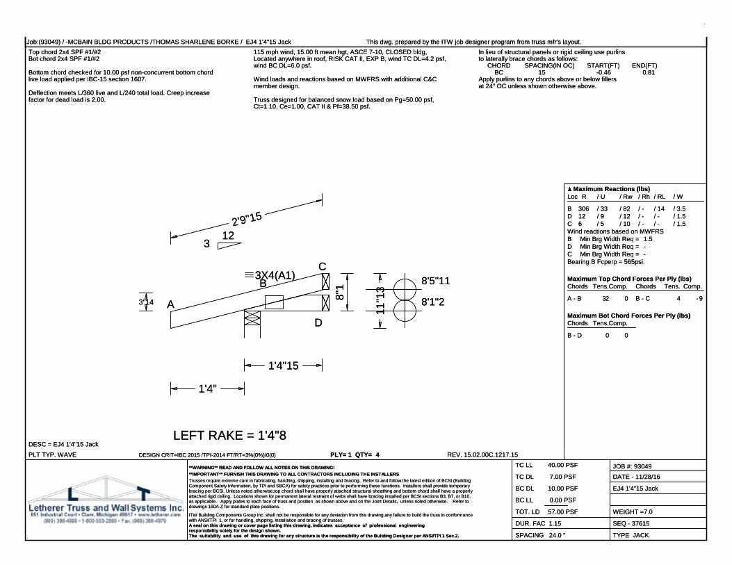
Job:(93049) / -MCBAIN BLDG PRODUCTS /THOMAS SHARLENE BORKE / EJ4 1'4"15 Jack This dwg. prepared by the ITW job designer program from truss mfr's layout.Top chord 2x4 SPF #1/#2Bot chord 2x4 SPF #1/#2
115 mph wind, 15.00 ft mean hgt, ASCE 7-10, CLOSED bldg,Located anywhere in roof, RISK CAT II, EXP B, wind TC DL=4.2 psf,wind BC DL=6.0 psf.
Wind loads and reactions based on MWFRS with additional C&Cmember design.
In lieu of structural panels or rigid ceiling use purlinsto laterally brace chords as follows: CHORD SPACING(IN OC) START(FT) END(FT) BC 15 -0.46 0.81Apply purlins to any chords above or below fillersat 24" OC unless shown otherwise above.
Bottom chord checked for 10.00 psf non-concurrent bottom chordlive load applied per IBC-15 section 1607.
Deflection meets L/360 live and L/240 total load. Creep increasefactor for dead load is 2.00. Truss designed for balanced snow load based on Pg=50.00 psf,
Ct=1.10, Ce=1.00, CAT II & Pf=38.50 psf.
PLT TYP. WAVEDESC = EJ4 1'4"15 Jack
DESIGN CRIT=IBC 2015 /TPI-2014 FT/RT=3%(0%)/0(0) PLY= 1 QTY= 4 REV. 15.02.00C.1217.15
Maximum Reactions (lbs)Loc R / U / Rw / Rh / RL / W
B 306 / 33 / 82 / - / 14 / 3.5D 12 / 9 / 12 / - / - / 1.5C 6 / 5 / 10 / - / - / 1.5Wind reactions based on MWFRSB Min Brg Width Req = 1.5D Min Brg Width Req = -C Min Brg Width Req = -Bearing B Fcperp = 565psi.
Maximum Top Chord Forces Per Ply (lbs)Chords Tens.Comp.
A - B 32 0
Chords Tens. Comp.
B - C 4 - 9
Maximum Bot Chord Forces Per Ply (lbs)Chords Tens.Comp.
B - D 0 0
**WARNING** READ AND FOLLOW ALL NOTES ON THIS DRAWING!**IMPORTANT** FURNISH THIS DRAWING TO ALL CONTRACTORS INCLUDING THE INSTALLERSTrusses require extreme care in fabricating, handling, shipping, installing and bracing. Refer to and follow the latest edition of BCSI (BuildingComponent Safety Information, by TPI and SBCA) for safety practices prior to performing these functions. Installers shall provide temporarybracing per BCSI. Unless noted otherwise,top chord shall have properly attached structural sheathing and bottom chord shall have a properlyattached rigid ceiling. Locations shown for permanent lateral restraint of webs shall have bracing installed per BCSI sections B3, B7, or B10,as applicable. Apply plates to each face of truss and position as shown above and on the Joint Details, unless noted otherwise. Refer todrawings 160A-Z for standard plate positions.
ITW Building Components Group Inc. shall not be responsible for any deviation from this drawing,any failure to build the truss in conformancewith ANSI/TPI 1, or for handling, shipping, installation and bracing of trusses.A seal on this drawing or cover page listing this drawing, indicates acceptance of professional engineeringresponsibility solely for the design shown.The suitability and use of this drawing for any structure is the responsibility of the Building Designer per ANSI/TPI 1 Sec.2.
TC LL 40.00 PSF
TC DL 7.00 PSF
BC DL 10.00 PSF
BC LL 0.00 PSF
TOT. LD 57.00 PSF
DUR. FAC 1.15
SPACING 24.0 "
JOB #: 93049DATE - 11/28/16
EJ4 1'4"15 Jack
WEIGHT =7.0
SEQ - 37615
TYPE JACK
2'9"15
1'4"15
1'4"
3"14 8"1
11"1
3
8'1"2
8'5"11
LEFT RAKE = 1'4"8
A
BC
D
312
3X4(A1)

![SummaryMap ward2 [Converted] · 2019-10-01 · MU-2 MU-6 MU-16 MU-14 MU-6 MU-2 MU-20 MU-9 MU-4 MU-13 MU-15 MU-13 MU-16 MU-18 MU-22 MU-19 MU-16 MU-27 MU-4 MU-3A MU-17 MU-13 MU-4 ...](https://static.fdocuments.us/doc/165x107/5f5e4f591750d150e9633369/summarymap-ward2-converted-2019-10-01-mu-2-mu-6-mu-16-mu-14-mu-6-mu-2-mu-20.jpg)