92100-ED PTH pressure
28
41 505/117 ED 1/28 41 505/117 ED DS(P)*M DIRECTIONAL VALVES WITh SPOOL POSITION MONITORING OPERATING PRINCIPLE DS3M DS5M DSP5M DSP5RM DSP7M DSP8M DSP10M Maximum operating pressure: P - A - B ports bar 350 320 320 350 350 350 T port 210 see performance limits at paragraph 5.5 Maximum flow rate from P to A - B - T l/min 80 120 150 300 600 1100 Ambient temperature range °C -20 / +50 Fluid temperature range °C -20 / +80 Fluid viscosity range cSt 10 ÷ 400 Fluid contamination degree According to ISO 4406:1999 class 20/18/15 Recommended viscosity cSt 25 Mass: single solenoid valve double solenoid valve kg 1,8 2,2 5 - 7,1 8 8,7 9,6 15,6 16,6 50 50.5 PERFORMANCES (working with mineral oil of viscosity of 36 cSt at 50°C) DS3M ISO 4401-03 DS5M ISO 4401-05 DSP5RM ISO 4401-05 DSP5M CETOP P05 DSP7M ISO 4401-07 DSP8M ISO 4401-08 DSP10M ISO 4401-10 — These solenoid operated directional valves are equipped with position sensors that monitor the main spool position. The switching position is indicated by a binary signal. — TÜV certification body certifies the compliance of DS(P)*M valves with the EC safety standards ISO 4413:2012, UNI EN 12622:2014, UNI EN 693:2001 +A2:2001, UNI EN 201:2010 and UNI EN 422:2009 with certificate TÜV IT 14 MAC 0043 . —The valves are available in direct current versions only (see paragraph 8). — These valves do not have manual override and can not be disassembled, because of their characteristics and their possible use on machinery subject to safety requirements. Moreover, their components are not inter- changeable. Read the Use and Maintenance manual for instructions on operation, safe use and repair of the product
Transcript of 92100-ED PTH pressure

41 505/117 ED 1/28
41 505/117 ED
DS(P)*M DIRECTIONAL vALvES
wITh SPOOL POSITIONMONITORING
OPERATING PRINCIPLE
DS3M DS5M DSP5MDSP5RM DSP7M DSP8M DSP10M
Maximum operating pressure: P - A - B ports bar
350 320 320 350 350 350
T port 210 see performance limits at paragraph 5.5
Maximum flow rate from P to A - B - T l/min 80 120 150 300 600 1100
Ambient temperature range °C -20 / +50
Fluid temperature range °C -20 / +80
Fluid viscosity range cSt 10 ÷ 400
Fluid contamination degree According to ISO 4406:1999 class 20/18/15
Recommended viscosity cSt 25
Mass: single solenoid valvedouble solenoid valve
kg1,82,2
5-
7,18
8,79,6
15,616,6
5050.5
PERFORMANCES(working with mineral oil of viscosity of 36 cSt at 50°C)
DS3M ISO 4401-03 DS5M ISO 4401-05
DSP5RM ISO 4401-05 DSP5M CETOP P05DSP7M ISO 4401-07 DSP8M ISO 4401-08 DSP10M ISO 4401-10
— These solenoid operated directional valves areequipped with position sensors that monitor themain spool position. The switching position isindicated by a binary signal.
— TÜV certification body certifies the complianceof DS(P)*M valves with the EC safety standardsISO 4413:2012, UNI EN 12622:2014, UNI EN693:2001 +A2:2001, UNI EN 201:2010 and UNI EN 422:2009 with certif icate TÜV IT 14 MAC 0043 .
— The valves are available in direct currentversions only (see paragraph 8).
— These valves do not have manual override andcan not be disassembled, because of theircharacteristics and their possible use onmachinery subject to safety requirements.Moreover, their components are not inter-changeable. Read the Use and Maintenancemanual for instructions on operation, safe useand repair of the product

41 505/117 ED 2/28
DS(P)*M
1 - IDENTIFICATION OF SOLENOID vALvES DIRECT OPERATED
1.1 - Identification code
Monitoring of the spool position
Series No. 20 = for DS5M21 = for DS3M(the overall and mounting dimensions remainunchanged from 20 to 29)
D S M - / - K1 /Directional control valvesolenoid operated
3 = ISO 4401-03 size5 = ISO 4401-05 size
Seals: N = NBR seals for mineral oil (standard)v = FPM seals for special fluids
DC power supplyD12 = 12 VD24 = 24 V
D110 = 110 VD220 = 220 V
Coil electrical connection: plug for connector type DIN 43650 (standard)
Monitored position: (see par. 16 for switching logic)R0 = monitored rest positionMA = monitored position ‘a’MB = monitored position ‘b’
NOTE: verify spool and sensor type availability in the tables below
DS3SPOOLS
S* SA* SB* TATA100
TBTB100
SE
NS
OR
TYP
E
R0 x
MA x x x x
MB x x x x
DS5SPOOLS
S* SA* SB* TATA100
TA02TB02
TBTB100
SE
NS
OR
TYP
E
R0 x
MA x x x x x
MB x x x x x
MAChINE DIRECTIvE CERTIFICATION All solenoid valves and solenoid operated valves of the DS(P)*M family were tested on a voluntary basis by TÜV and found to comply with the applicable requirements of the following standards: UNI EN ISO 4413:2012 - Hydraulic fluid power – General rules and safety requirements for systems and their
components UNI EN 12622:2014 - Safety of machine tools - Hydraulic press brakes UNI EN 693:2001+A2:2011 - Machine tools – Safety – Hydraulic presses UNI EN 201:2010 - Plastics and rubber machines - Injection moulding machines - Safety requirements UNI EN 422:2009 - Rubber and Plastic machines – Safety requirements
Spool type (see par. 1.2)S1 SA1 SB1 TA TBS3 TA02 TB02S4 SA4 SB4 TA100 TB100
NOTE: To be compliant with the EN 693:2011standard, the valves have no manual override.

41 505/117 ED 3/28
DS(P)*M
1.2 - Spool types for DS3M and DS5M
Type S*:2 solenoids - 3 positions
with spring centering
Sensor RO
Type TA:1 solenoid side A
2 external positions with return spring
Sensor MA Sensor MB
Type TB:1 solenoid side B
2 external positions with return spring
Sensor MA Sensor MB
Type SA*:1 solenoid side A
2 positions (central + external) with spring centering
Sensor MA Sensor MB
Type SB*:1 solenoid side B
2 positions (central + external) with spring centering
Sensor MA Sensor MB

41 505/117 ED 4/28
DS(P)*M
2.3 - Performance limits for DS3M and DS5M solenoid valvesThe curves define the flow rate operating fields according to the valve pressure of the different versions.The values have been obtained according to ISO 6403 norm with solenoids at rated temperature and supplied with voltage equal to 90% of thenominal voltage. The values have been obtained with mineral oil, viscosity 36 cSt, temperature 50 °C and filtration according to ISO 4406:1999class 18/16/13. The operating limits can be considerably reduced if a 4-way valve is used as 3-way valve with port A or B plugged or without flow.
SPOOL CURvE
P→A P→BS1,SA1 1 1S3, 4 4S4, SA4 2 2TA, TB 1 1TA100, TB100 3 3
SPOOL CURvE
P→A P→BS1 1 1S3 3 3S4 2 2TA02 1 1TA, TA100 1 1
DS5MDS3M
2.2 - DS5M - Pressure drops ∆p-Q
2 - ChARACTERISTIC CURvES OF DIRECT OPERATED SOLENOID vALvES (obtained with viscosity 36 cSt at 50 °C)
2.1 - DS3M - Pressure drops ∆p-Q
SPOOL TYPEFLOW DIRECTION
P→A P→B A→T B→T P→TCURVES ON GRAPH
S1, SA1; SB1 2 2 3 3 -S3 3 3 1 1 -S4, SA4 5 5 5 5 3TA, TB 2 2 2 2 -TA100, TB100 4 4 4 4 -
SPOOL TYPEFLOW DIRECTION
P→A P→B A→T B→T P→TCURVES ON GRAPH
S1, SA1, SB1 2 2 1 1S3 2 1 2 3S4, SA4, SB4 1 1 2 2 4TA, TB, TA02, TB02 3 3 2 2 -TA100, TB100 2 2 2 2 -
For S3 in central position B→T refer to curve 3.
For S3 in central position B→T refer to curve 5.

41 505/117 ED 5/28
DS(P)*M
3 - OvERALL AND MOUNTING DIMENSIONS FOR DIRECT OPERATED vALvES
dimensions in mm
1 Mounting surface with sealing rings:4 OR type 2037 (9.25x1.78)90 Shore
2 Coil rotating 360°
3 Positioning sensor: setting sealed atfactory, do not tamper.
4 Connector for positioning sensortype straight, molded. To be ordered separately, see par.17
5 Coil electric connector DIN 43650 typeto be ordered separatelycat. 49 000
Valve fastening: 4 SHC screws ISO 4762 M5x30
Tightening torque: 5 Nm (A8.8)
Threads of mounting holes: M5x10
2.4 - Switching timesThe indicated values had obtained according to ISO 6403 standards, using mineral oil with viscosity 36 cSt at 50 °C.
TIMES [ms] ENERGIZING DE-ENERGIZING
DS3M 25 ÷ 75 15 ÷ 25
TIMES [ms] ENERGIZING DE-ENERGIZING
DS5M 100 ÷ 150 20 ÷ 50
DS3M-S*
DS3M-TADS3M-TA*DS3M-SA*
DS3M-TBDS3M-TB*DS3M-SB*
sensor type:R0
sensor type:MAMB

41 505/117 ED 6/28
DS(P)*M
dimensions in mm
Valve fastening: 4 SHC screws ISO 4762 M6x40
Tightening torque: 8 Nm
Threads of mounting holes: M6x10
DS5M-TADS5M-TA*
DS5M-S*
DS5M-TBDS5M-TB*
1 Mounting surface withsealing rings. 5 OR type 2050(12.42x1.78) - 90 Shore
2 Coil rotating 360°
3 Positioning sensor: setting sealed at factory, do not tamper.
4 Connector for positioningsensor type straight,molded. To be ordered separately, see par. 17
5 Coil electric connectorDIN 43650 typeto be ordered separately cat. 49 000
sensor type:R0
sensortype:MAMB

41 505/117 ED 7/28
DS(P)*M
Size:5 = CETOP P055R = ISO 4401-05 7 = ISO 4401-07 8 = ISO 4401-08 10 = ISO 4401-10
P = Subplate with restrictor on port P placed under the pilot valve (omit for valves with piloting type Z and for valveswith option D - control of the shifting speed of themain spool)D = shifting speed of the main spool (see par. 7)
Directional valve,Solenoid controlledPilot operated
Spool type (see paragraph 4.2)S1 SA1 SB1 TA TBS3 TA100 TB100S4RK
Series: 10 = for DSP5M, DSP5RM and DSP8M20 = for DSP7M30 = for DSP10M(the overall and mounting dimensions within the sameten remain unchanged)
Seals: N = NBR seals for mineral oil (standard)v = FPM seals for special fluids
Drainage (see paragraph 6):I = InternalE = External
Piloting (see paragraph 6):I = internal (not available for S4 spool)E = externalC = internal piloting with backpressure valve (available on DSP7 and DSP8 only)Z = internal piloting with 30 bar fixes adjustment pressure reducing valve (see par. 5.5)
D S P M / / /- / -
Monitoring of the spool position
DC power supplyD12 = 12 VD24 = 24 V
D110 = 110 VD220 = 220 V
Coil electrical connection: plug for connector typeDIN 43650 (standard)
Monitored position: (see par. 16 for switchinglogic)1 positioning sensor R0 = rest position monitoredMA = position ‘a’ monitoredMB = position ‘b’ monitored 2 positioning sensor M0 = rest position monitoredMAB = ‘a’ and ‘b’ positions monitored
NOTE: To be compliant with the EN 693:2011standard, the valves have no manual override.
verify spool and sensor type availability in the table below
NOTE: DSP10M available with spools S1 or S4, with monitoredposition R0 or M0 only.
SPOOLS
S* SA*SB*
TA TB
TA100TB100 RK
SE
NS
OR
TY
PE
R0 x
MA x x x x
MB x x x x
M0 x
MAB x x x x
K1
4 - IDENTIFICATION OF PILOT OPERATED SOLENOID vALvES
4.1 - Identification code

41 505/117 ED 8/28
DS(P)*M
4.2 - Spool types for DSP5M, DSP5RM, DSP7M and DSP8M
Type S*:2 solenoids - 3 positions with spring centering
sensor R0 sensor M0 sensor MAB
sensor MA sensor MB sensor MAB
sensor MA sensor MB sensor MAB
sensor MA sensor MB
Type TA:1 solenoid side A
2 external positionswith return spring
Type TB:1 solenoid side B
2 external positionswith return spring
Type SA*:1 solenoid side A
Type SB*:1 solenoid side B
2 positions (central + external)with spring centering
Type RK:2 solenoids - 2 positionswith mechanical detent

41 505/117 ED 9/28
DS(P)*M5 - ChARACTERISTIC CURvES AND PERFORMANCES(values obtained with viscosity 36 cSt at 50 °C)
5.1 - DSP5M and DSP5RM - Pressure drops ∆p-Q
5.2 - DSP7M - Pressure drops ∆p-Q
5.3 - DSP8M - Pressure drops ∆p-Q
SPOOL TYPEFLOW DIRECTION
P→A P→B A→T B→T P→TCURVES ON GRAPH
S1, SA1 4 4 1 1 -S3 4 4 1 1 -S4 5 5 2 3 5TA, TB 4 4 1 1 -TA100, TB100 3 3 1 1 -RK 4 4 1 1 -
SPOOL TYPEFLOW DIRECTION
P→A P→B A→T B→T P→TCURVES ON GRAPH
S1, SA1 1 1 4 5 -S3 1 1 5 5 -S4 2 2 5 6 5TA, TB 1 1 4 5 -TA100, TB100 3 3 3 5 -RK 1 1 4 5 -
SPOOL TYPEFLOW DIRECTION
P→A P→B A→T B→T P→TCURVES ON GRAPH
S1, SA1 2 2 3 3 -S3 2 2 2 1 -S4 4 4 3 5 6TA, TB 2 2 3 3 -TA100, TB100 5 5 5 5 -RK 2 2 3 3 -
For pressure drops of the S3 spool in central position refer to thecurve 4.
For pressure drops of the S3 spool in central position refer to thecurve 5.
For pressure drops of the S3 spool in central position refer to thecurve 4.

41 505/117 ED 10/28
DS(P)*M
5.5 - Performance limits for pilot operated valves
5.6 - Switching timesThe values indicated refer to a solenoid valve working with pilotingpressure of 100 bar, with mineral oil at a temperature of 50°C, atviscosity of 36 cSt and with PA and BT connections. The energizing and de-energizing times are obtained at thepressure variation which occurs on the lines.
TIMES (± 10%)[ms]
ENERGIZING DE-ENERGIZING
2 Pos. 3 Pos. 2 Pos. 3 Pos.
DSP5M - DSP5RM 60 50 50 40
DSP7M 75 60 60 45
DSP8M 100 70 80 50
DSP10M - 100 - 140
MAXIMUM FLOw RATES DSP5MDSP5RM DSP7M DSP8M DSP10M
Spool typePRESSURES
210 bar 320 bar 210 bar 350 bar 210 bar 350 bar 210 bar 350 bar
S4 - TA100[l/min]
120 100 200 150 500 450 750 600
S1 - S3 - TA - RK 150 120 300 300 600 500 900 700
NOTE 1: minimum piloting pressure can be the lower range value at low flows rates, but with higher flow rates the higher value is needed.NOTE 2: if the valve operates with higher pressures it is necessary to use the version with external pilot and reduced pressure. Otherwise, thevalve with internal pilot and pressure reducing valve with 30 bar fixed adjustment can be ordered. Add the letter Z to the identification code to order this option (see par. 4.1).
PRESSURES DSP5MDSP5RM DSP7M DSP8M DSP10M
Max pressure in P, A, B ports 320 350 350 350
Max pressure in T line 210 210 210 210
Max pressure in Y line 210 210 210 210
Min piloting pressure NOTE 1 5 ÷ 10 5 ÷ 12 7 ÷ 14 6 ÷ 12
Max piloting pressure NOTE 2 210 210 210 280
5.4 - DSP10M - Pressure drops ∆p-Q
SPOOL TYPEFLOW DIRECTION
P→A P→B A→T B→T P→TCURVES ON GRAPH
S1 1 1 1 1 -S4 2 2 2 2 -

41 505/117 ED 11/28
DS(P)*M
The curve refers to the pressure drop (body partonly) with backpressure valve inside, to whichthe pressure drop of the reference spool must beadded. (see par. 5)
DSP8MDSP7M
X: plug M5x6 for external pilotY: plug M5x6 for external drain
T
6 - PILOTING AND DRAINAGEThese valves are available with piloting and drainage, both internal andexternal. The version with external drainage allows for a higher back pressureon the outlet.
P
TYPE OF VALVEPlug assembly
X Y
IE internal pilot and external drain NO YES
II Internal pilot and internal drain NO NO
EE external pilot and external drain YES YES
EI external pilot and internal drain YES NO
6.1 - Backpressure valve incorporated on line P (C option)DSP7M and DSP8M valves are available upon request with backpressure valve incorporated on line P. This is necessary to obtain the pilotingpressure when the control valve, in rest position, has the line P connected to the T port (spools S4).The cracking pressure is of 5 bar with a minimum flow rate of 15 l/min. In the C version the piloting is always internal.NOTE: the backpressure valve can’t be used as check valve because it doesn’t assure the seal.
Add C to the identification code for this request (see paragraph 4.1). For DSP7M only, the backpressure valve can be also delivered separately and it can be easily mounted on lineP of the main control valve. Ask for code 0266577 to order the backpressure valve.
pilot always internalY: plug M6x8 for external drain
DSP8M DSP10MDSP7MDSP5MDSP5RM
X: plug M6x8 for external pilotY: plug M6x8 for external drain
41 505/117 ED 12/28
DS(P)*M
SuffixNominalvoltage
[V]
Resistance at 20°C
[Ω]
Currentconsumpt.
[A]
Powerconsumpt
[W]
Coil code
D12 12 4,4 2,72 32,7 1903080
D24 24 18,6 1,29 31 1903081
D110 110 436 0,26 28,2 1903464
D220 220 1758 0,13 28,2 1903465
SuffixNominalvoltage
[V]
Resistance at 20°C
[Ω]
Currentconsumpt.
[A]
Powerconsumpt
[W]
Coil code
D12 12 3,2 3,75 45 1903550
D24 24 12 2 48 1903551
D110 110 250 0,44 48 1903554
D220 220 1050 0,21 47 1903555
DS3M, DSP5M, DSP5RM, DSP7M, DSP8M and DSP10M(values ± 10%) DS5M (values ± 5%)
vOLTAGE SUPPLY FLUCTUATION ± 10% Vnom
MAX SwITCh ON FREQUENCYDS3MDS5MDSP5M - DSP5RMDSP7MDSP8MDSP10M
15.000 ins/hr13.000 ins/hr5.000 ins/hr5.000 ins/hr4.000 ins/hr3.000 ins/hr
DUTY CYCLE 100%
ELECTROMAGNETIC COMPATIBILITY(EMC) (NOTE 1)
In compliance with2014/30/EU
LOw vOLTAGE In compliance with2014/35/EU
CLASS OF PROTECTION:Atmospheric agents (IEC 60529)Coil insulation (VDE 0580)Impregnation
IP65 (NOTE 2)class Hclass F
8 - ELECTRICAL FEATURES
8.1 - SolenoidsThese are essentially made up of two parts: tube and coil. The tubeis threaded into the valve body and includes the armature thatmoves immersed in oil, without wear. The inner part, in contact withthe oil in the return line, ensures heat dissipation.The coil is fastened to the tube by a threaded ring, and can berotated and locked to suit the available space.
NOTE 1 : In order to further reduce the emissions, use of type Hconnectors is recommended. These prevent voltage peaks onopening of the coil supply electrical circuit (see catalogue 49 000).
NOTE 2: The IP65 protection degree is intended for the wholevalve. It is guaranteed only with valve and connectors correctlyconnected and installed.
8.2 - Current and absorbed power The tables shows current and power consumption values relevantto the different coil types for DC.
7 - OPTIONS
7.1 - Option D : control of the main spool shifting speedBy placing a MERS type double flow control valve between the pilot solenoid valve andthe hydropiloted valve, the piloted flow rate can be controlled and therefore the changeover smoothness can be varied.
Add the letter D to the identification code to request this device (see paragraph 4.1).
dimensions in mm
DSP5 DSP7 DSP8 DSP10
A 218 225 254 307
9 - COIL CONNECTORSThe solenoid operated valves are delivered without the connectors. They can be ordered separately.For the identification of the connector type to be ordered, please see catalogue 49 000.

41 505/117 ED 13/28
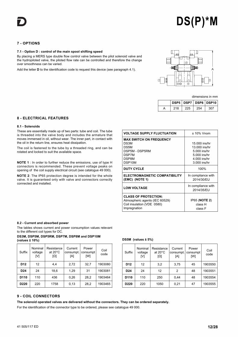
DS(P)*M10 - DSP5M AND DSP5RM OvERALL AND MOUNTING DIMENSIONS
dimensions in mmDSP5M-S*DSP5RM-S*
Valve fastening: 4 SHC screws ISO 4762 M6x35
Tightening torque: 8 Nm (screws A 8.8)
Threads of mounting holes: M6x10
1 Mounting surface with sealing rings5 OR type 2050 (12.42x1.78) - 90 Shore2 OR type 2037 (9.25x1.78) - 90 Shore
2 Position sensor: set and sealed at factory, donot tamper.
3 Connector for positioning sensor, typestraight, molded. To be ordered separately, see par. 17
4 Coil electric connector DIN 43650 type To be ordered separately see cat. 49 000
sensor type:M0MAB
sensor type:R0
NOTE: for overall dimensions with Z option (fixed adjustmentpressure reducing valve) consider an increase of 30 mm in height.

41 505/117 ED 14/28
DS(P)*M
NOTE: for overall dimensions with Z option (fixed adjustmentpressure reducing valve) consider an increase of 30 mm in height.
dimensions in mmDSP5M-TA, TA100, SA1DSP5RM-TA, TA100, SA1
Solenoid positionfor TB and SB*versions
sensor type:MAB
sensor type:MAMB
Solenoid positionfor TB and SB*versions
sensor positionfor TB and SB*versions
1 Mounting surface with sealing rings5 OR type 2050 (12.42x1.78) - 90 Shore2 OR type 2037 (9.25x1.78) - 90 Shore
2 Position sensor: set and sealed at factory, donot tamper.
3 Connector for positioning sensor, typestraight, molded. To be ordered separately, see par. 17
4 Coil electric connector DIN 43650 type To be ordered separately see cat. 49 000
41 505/117 ED 15/28
DS(P)*M
1 Mounting surface with sealing rings5 OR type 2050 (12.42x1.78) - 90 Shore2 OR type 2037 (9.25x1.78) - 90 Shore
2 Position sensor: set and sealed at factory, donot tamper.
3 Connector for positioning sensor, typestraight, molded. To be ordered separately, see par. 17
4 Coil electric connector DIN 43650 type To be ordered separately see cat. 49 000
dimensions in mmDSP5M-RKDSP5RM-RK
sensor type:MAMB
NOTE: for overall dimensions with Z option (fixed adjustmentpressure reducing valve) consider an increase of 30 mm in height.

41 505/117 ED 16/28
DS(P)*M11 - DSP7M OvERALL AND MOUNTING DIMENSIONS
dimensions in mmDSP7M-S*
sensor type:M0MAB
sensor type:R0
Valve fastening: 4 SHC screws ISO 4762 M10x60 2 SHC screws ISO 4762 M6x50
Tightening torque: M10x60: 40 Nm M6x50: 8 Nm
Threads of mounting holes: M6x18; M10x18
1 Mounting surface with sealing rings.4 OR type 130 (22.22x2.62) - 90 Shore2 OR type 2043 (10.82x1.78) - 90 Shore
2 Position sensor: set and sealed at factory, donot tamper.
3 Connector for positioning sensor, typestraight, molded. To be ordered separately, see par. 17
4 Coil electric connector DIN 43650 type To be ordered separately see cat. 49 000
NOTE: for overall dimensions with Z option (fixed adjustmentpressure reducing valve) consider an increase of 30 mm in height.

41 505/117 ED 17/28
DS(P)*M
dimensions in mmDSP7M-TA, TA100, SA1
Solenoid positionfor TB and SB*versions
sensor type:MAB
sensor type:MAMB
Solenoid positionfor TB and SB*versions
sensor positionfor TB and SB*versions
1 Mounting surface with sealing rings.4 OR type 130 (22.22x2.62) - 90 Shore2 OR type 2043 (10.82x1.78) - 90 Shore
2 Position sensor: set and sealed at factory, donot tamper.
3 Connector for positioning sensor, typestraight, molded. To be ordered separately, see par. 17
4 Coil electric connector DIN 43650 type To be ordered separately see cat. 49 000
NOTE: for overall dimensions with Z option (fixed adjustmentpressure reducing valve) consider an increase of 30 mm in height.

41 505/117 ED 18/28
DS(P)*M
dimensions in mmDSP7M-RK
sensor type:MAMB
1 Mounting surface with sealing rings.4 OR type 130 (22.22x2.62) - 90 Shore2 OR type 2043 (10.82x1.78) - 90 Shore
2 Position sensor: set and sealed at factory, donot tamper.
3 Connector for positioning sensor, typestraight, molded. To be ordered separately, see par. 17
4 Coil electric connector DIN 43650 type To be ordered separately see cat. 49 000
NOTE: for overall dimensions with Z option (fixed adjustmentpressure reducing valve) consider an increase of 30 mm in height.

41 505/117 ED 19/28
DS(P)*M12 - DSP8M OvERALL AND MOUNTING DIMENSIONS
dimensions in mm
Valve fastening: 6 SHC screws ISO 4762 M12x60
Tightening torque: 69 Nm
Threads of mounting holes: M12x20
DSP8M-S*
sensor type:M0MAB
sensor type:R0
1 Mounting surface with sealing rings.4 OR type 3118 (29.82x2.62) - 90 Shore2 OR type 3081 (20.24x2.62) - 90 Shore
2 Position sensor: set and sealed at factory, donot tamper.
3 Connector for positioning sensor, typestraight, molded. To be ordered separately, see par. 17
4 Coil electric connector DIN 43650 type To be ordered separately see cat. 49 000
NOTE: for overall dimensions with Z option (fixed adjustmentpressure reducing valve) consider an increase of 30 mm in height.

41 505/117 ED 20/28
DS(P)*M
dimensions in mmDSP8M-TA, TA100, SA1
Solenoid positionfor TB and SB*versions
sensor type:MAB
sensor type:MAMB
Solenoid positionfor TB and SB*versions
sensor positionfor TB and SB*versions
1 Mounting surface with sealing rings.4 OR type 3118 (29.82x2.62) - 90 Shore2 OR type 3081 (20.24x2.62) - 90 Shore
2 Position sensor: set and sealed at factory, donot tamper.
3 Connector for positioning sensor, typestraight, molded. To be ordered separately, see par. 17
4 Coil electric connector DIN 43650 type To be ordered separately see cat. 49 000
NOTE: for overall dimensions with Z option (fixed adjustmentpressure reducing valve) consider an increase of 30 mm in height.

41 505/117 ED 21/28
DS(P)*M
dimensions in mmDSP8M-RK
sensor type:M0MAB
1 Mounting surface with sealing rings.4 OR type 3118 (29.82x2.62) - 90 Shore2 OR type 3081 (20.24x2.62) - 90 Shore
2 Position sensor: set and sealed at factory, donot tamper.
3 Connector for positioning sensor, typestraight, molded. To be ordered separately, see par. 17
4 Coil electric connector DIN 43650 type To be ordered separately see cat. 49 000
NOTE: for overall dimensions with Z option (fixed adjustmentpressure reducing valve) consider an increase of 30 mm in height.

41 505/117 ED 22/28
DS(P)*M13 - DSP10M OvERALL AND MOUNTING DIMENSIONS
dimensions in mmDSP8M-S*
sensor type:M0
sensor type:R0
1 Mounting surface with sealing rings.4 OR type 4150 (37.59x3.53) - 90 shore2 OR type 3081 (20.24x2.62) - 90 shore
2 Positioning sensor : setting sealed at factory, do not tamper.
3 Connector for positioning sensor, typestraight, molded. To be ordered separately, see par. 17
4 Coil connector DIN 43650 type To be ordered separately see cat. 49 000
NOTE: for overall dimensions with Z option (fixed adjustmentpressure reducing valve) consider an increase of 30 mm in height.
Valve fastening: 6 SHC screws ISO 4762 M20x70
Tightening torque: 330 Nm (A8.8 screws)
Threads of mounting holes: M20x40
490

41 505/117 ED 23/28
DS(P)*M
50.8
37.3
27
3.2
16.7
54
M6x10
facoltativo
Attacco "T"
BA
P
T
Ø11.2 (max)
46 32
.5
21
.4
6.3
14 - MOUNTING SURFACES
0.750.75
TT
BB31.7531.75
PP
AA25.925.915.515.5
5.15.1
12.712.7
3131
M5M5
Ø4Ø4
Ø7.5 (max)Ø7.5 (max)
21.521.5
30.230.2
40.540.5
3333
DS3MISO 4401-03-02-0-05(CETOP 4.2-4-03-350)
Ø6.3 (max)
attacco "T"
M6
facoltativo
54
65.1
50.8
27
37.3
B
P
A
11.1
3.2
16.7
Ty
Ø11.2 (max)
x
46
43
.6
32
.5
21
.4
6.3
2.4
54
62
50.8
y
P
B
facoltativo
M6
attacco "T"
Ø6.3 (max)8
3.2
16.7
Tx A
Ø11.2 (max)
37.3
27
46 32.5
21.4
11 6.3
DSP5MCETOP 4.2-4 P05-320
DSP5RMISO 4401-05-05-0-05(CETOP 4.2-4 R05-320)
101.6
88.1
76.6
65.9
50
34.1
Y
Ø4
M10
Ø6.3 (max)
BA
P
L
T
G
M6
X
G
18.3
Ø17.5 (max)
71.5
69.8 57
.2
55.6 34.9
15.9
14.3
1.6
DSP7MISO 4401-07-07-0-05(CETOP 4.2-4-07-350)
DS5MISO 4401-05-04-0-05(CETOP 4.2-4-05-320)
130.2112.7
G
Ø25 (max)
M 12
P
B
Y
Ø7.5
53.229.417.5
5.6
L
X
G
Ø11.2 (max)
A
T
7794.5100.8
92.1
74.6
73 4
6
19
17.5
4.8
DSP8MISO 4401-08-08-0-05(CETOP 4.2-4-08-350)
Optionalport ‘T’
Optionalport ‘T’Optional
port ‘T’

41 505/117 ED 24/28
DS(P)*M
15 - POSITIONING SENSORSwARNING ! The disassembly of the valve is notallowed. The sensors must not be unscrewed ortampered with in any way.
The M0 and MAB versions have two positioning sensors; considerthat the connection scheme shown must be done for each sensor.
ELECTRICAL ChARACTERISTICS
Operating voltage range V DC 20 ÷ 32
Absorbed current A 0.4
Max output load mA 400
Output 2 PNP
Electric protections polarity inversionshort circuit
Hysteresis mm ≤ 0.1
Operating temperature range °C -25 / +80
Class of protection fromatmospheric agents (IEC 60529)
IP65
EMC Electromagnetic compatibility
In compliance with2014/30/EU
R0 CONNECTION SChEME M* CONNECTION SChEME
Pin values Function
1 +24 V Supply
2 NC Normal Closed -
3 0 V -
4 NC Normal Closed +
Pin values Function
1 +24 V Supply
2 NC Normal Closed
3 0 V -
4 NO Normal Open
190.5
168.3
Y
G
P
76.2
114.3
82.5
T
138.6
147.6
M 20
Ø 32 (max)Ø 7.5
G
XA B
41.3
Ø 11.2 (max)
158.8
130.2
123.8
44.5
35
DSP10MISO 4401-10-09-0-05(CETOP 4.2-4-10-350)
41 505/117 ED 25/28
DS(P)*M
spiega sul monitoraggio???
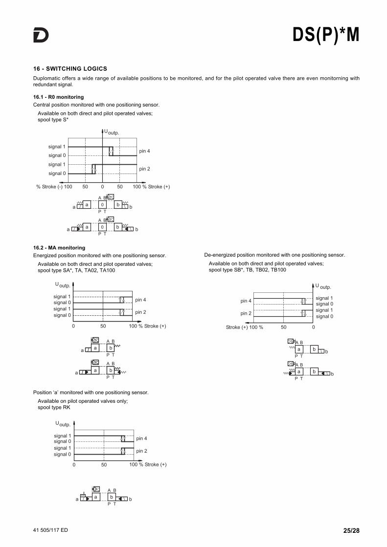
16.2 - MA monitoringEnergized position monitored with one positioning sensor.
Available on both direct and pilot operated valves;spool type SA*, TA, TA02, TA100
De-energized position monitored with one positioning sensor. Available on both direct and pilot operated valves;spool type SB*, TB, TB02, TB100
16 - SwITChING LOGICSDuplomatic offers a wide range of available positions to be monitored, and for the pilot operated valve there are even monitorning withredundant signal.
16.1 - R0 monitoringCentral position monitored with one positioning sensor.
Available on both direct and pilot operated valves;spool type S*
Position ‘a’ monitored with one positioning sensor. Available on pilot operated valves only;spool type RK

41 505/117 ED 26/28
DS(P)*M
16.4 - M0 monitoringCentral position monitored by two separate positioning sensors.
Available on pilot operated valves only;spool type S*
Sen
sor
side
“A”
Sen
sor
side
“B”
16.3 - MB monitoringDe-energized position monitored with one positioning sensor.
Available on both direct and pilot operated valves;spool type SA*, TA, TA02, TA100
Energized position monitored with one positioning sensor. Available on both direct and pilot operated valves;spool type SB*, TB, TB02, TB100
Position ‘b’ monitored with one positioning sensor. Available on pilot operated valves only;spool type RK

41 505/117 ED 27/28
DS(P)*M
16.5 - MAB monitoringBoth external positions monitored by two separate positioningsensors.
Available on pilot operated valves only;spool type S*
De-energized position monitored on side A.Energized position monitored on side B.
Available on pilot operated valves only;spool type SA1, TA, TA100
Energized position monitored on side A.De-energized position monitored on side B.
Available on pilot operated valves only;spool type SB1, TB, TB100
Sen
sor
side
“A”
Sen
sor
side
“B”
Sen
sor
side
“A”
Sen
sor
side
“B”
Sen
sor
side
“A”
Sen
sor
side
“B”

17 - SENSOR CONNECTORSThe female connectors for position switches can be ordered separately, by specifying the descriptions here below, depending on the desired type.
STRAIGhT CONNECTOR, MOLDED CABLE, PRE-wIREDdescription: ECM4S/M12L/10
Protection class: IP68Cable: 4 conductors 0.34 mm2
length 5 mt - Ø 4.7 mmCable material: polyurethaneresin (oil resistant)Without LED.
ANGLED CONNECTOR, MOLDED CABLE, PRE-wIRED description: ECM4S/M12S/10
Protection class: IP68Cable: 4 conductors 0.34 mm2
length 5 mt - Ø 4.7 mmCable material: polyurethane resin(oil resistant)Without LED.
ANGLED CONNECTOR, UNASSEMBLEDCircular connector with screw locking; strain relief by means ofclamping cage.description: EC4S/M12S/10
Protection class: IP67IEC 61076-2-101 (Ed. 1)IEC 60947-5-2Conductor size: max 0.75 mm2
Cable gland: PG7 suitable cables: 4 ÷ 6 mm2
Case material: polyamide (nylon)Without LED.
41 505/117 ED 28/28
DUPLOMATIC OLEODINAMICA S.p.A.20015 PARABIAGO (MI) Via M. Re Depaolini 24Tel. +39 0331.895.111Fax +39 0331.895.339www.duplomatic.com e-mail: [email protected]
DS(P)*M
REPRODUCTION IS FORBIDDEN. THE COMPANY RESERVES THE RIGHT TO APPLY ANY MODIFICATIONS.
DS3M DS5M DSP5M DSP7M DSP8M
Type with rear ports PMMD-AI3G PMD4-AI4G PME4-AI5G PME07-AI6G -
Type with side ports PMMD-AL3G PMD4-AL4G PME4-AL5G PME07-AL6G PME5-AL8G
P, T, A, B ports dimensions
X, Y ports dimensions
3/8” BSP
-
3/4” BSP (PMD4-AI4G)1/2” BSP (PMD4-AL4G)
-
3/4” BSP
1/4” BSP
1” BSP
1/4” BSP
1 ½” BSP
1/4” BSP
20 - SUBPLATES(see catalogue 51 000)
Surface finishing
18 - hYDRAULIC FLUIDSUse mineral oil-based hydraulic fluids HL or HM type, according to ISO 6743-4. For these fluids, useNBR seals (code N). For fluids HFDR type (phosphate esters) use FPM seals (code V). For the use ofother fluid types such as HFA, HFB, HFC, please consult our technical department.Using fluids at temperatures higher than 80 °C causes a faster degradation of the fluid and of the sealscharacteristics. The fluid must be preserved in its physical and chemical characteristics.
19 - INSTALLATIONwARNING ! These valves must be installed and commissioned by qualified personnelonly. Before starting any installation, commissioning or maintenance is mandatory readthe manual of use and maintenance, delivered together with the valve.
Configurations with centering and recall springs can be mounted in any position; The RK versions,without springs and with mechanical detent, must be mounted with the longitudinal axis horizontal.Valve fastening takes place by means of screws or tie rods, laying the valve on a lapped surface, withvalues of planarity and smoothness that are equal to or better than those indicated in the drawing. If the minimum values of planarity or smoothness are not met, fluid leakages between valve andmounting surface can easily occur.