905-656-X 08-10 CSM - RTG Rammtechnik · After reaching the design depth, the mixing tool ......
16
8/2010 CSM PROCESS DESCRIPTION Cutter Soil Mixing Process and equipment
Transcript of 905-656-X 08-10 CSM - RTG Rammtechnik · After reaching the design depth, the mixing tool ......

8/2010
CSMP R O C E S S D E S C R I P T I O N
Cutter Soil MixingProcess and equipment
905-656-X_08-10_CSM.qxd 05.08.2010 14:31 Uhr Seite 1

MBG xx – Bauer Maschinen GmbH, www.bauer.de
2
Mixing of self-hardening slurries with native soils by using a modified trench cutter technique is a new andeffective method for constructing: Cut-off walls; earth retaining walls; soil improvement or for constructing foundation elements.
CSM is used mainly for stabilizing soft or loose soils (noncohesive and cohesive), however the machinery used,derived from Bauer’s cutter technology, extends theapplicability of the method to much harder strata whencompared to other methods of soil mixing.
Main advantages of the method are:• High productivity
• The in-situ soil is used as a construction material
• Very little generation of spoil (important factor incontaminated areas)
• No vibrations induced during construction
• Extended depths (up to 60 m) can be reached – when using the rope suspended units.
CSM-Process
905-656-X_08-10_CSM.qxd 05.08.2010 14:31 Uhr Seite 2

3
© BAUER Maschinen GmbH, 8/2010 CSM Cutter Soil Mixing
1 2 3 4
Construction sequencePreparation:
Excavation of a guide trench for collecting surplus slurry
Step 1: Positioning of the cutter head in wall axis. The construction of a guide wall is not required.
Step 3: After reaching the design depth,the mixing tool is slowly extractedwhile cement slurry is conti-nuously added. Homogenizationof the fluidified soil mixture withthe fresh cement slurry is ensuredby the rotation of the wheels.
Step 4: Reinforcing elements required forstructural purposes can beinserted into the completed wall.A standard case is the insertion ofsteel stanchions. In shallowdepths these will usuallypenetrate under their own weight;otherwise a light vibrator can beused to assist their installation.The distance of the beams andbeam cross-sections aredesigned on the basis of theapplied loads and on the resultsof the characteristic strength ofthe soil.
Step 2: The mixing tool is driven into the ground at a continuous rate.The soil matrix is broken up by the cutting wheels and at thesame time a fluid is pumped to the nozzles, set between thecutting wheels, where it is mixed thoroughly with theloosened soil. Adding a compressed airstream can improvethe breaking and mixing process in the downstroke phase.The direction of rotation of the wheels can be varied at anytime. The rotating wheels and cuttingteeth push the soil particles throughvertically mounted shear plates thathave the effect of a compulsory mixer.Penetration speed of the cutter and thevolume of fluid pumped in are adjustedby the operator to optimise theabsorption of power and to create ahomogeneous, plastic soil mass whichpermits easy penetration and extractionof the machine. Typical speed ofpenetration is 20 – 60 cm/min.
905-656-X_08-10_CSM.qxd 05.08.2010 14:31 Uhr Seite 3

4
CSM Cutter Soil Mixing © BAUER Maschinen GmbH, 8/2010
Construction sequenceA continuous wall is formed in a series of overlapping primaryand secondary panels. Overcutting into fresh adjacent panelsis called „fresh-in-fresh method“. The cutter technique also allows the “hard-in-hard method”,whereby secondary panels are cut into the already hardenedprimary panels.
The cutting and mixing procedure can be executed in two ways:
One-phase systemDuring the penetration (downstroke) phase, cutting, mixing,fluidifying and homogenising is performed while pumping thebinder slurry into the soil. Adding compressed air isrecommended for assisting the downstroke phase. As a ruleof thumb about 70 % of the total slurry volume is pumpedduring this phase. The backflow of soil and binder slurry iscollected in the pre-excavated trench or stored in a settlingpond to be removed later off the site.
After reaching the design depth air flow is stopped. In theupstroke phase the remaining volume of binder slurry isblended into the soil. The speed of extraction can be high asthe majority of the binder slurry has already been mixed withthe soil in the downstroke phase.
Advantages of the one-phase system are:• No auxiliary desanding circuit required.
• Higher speed of extraction
• Preferred application in easy and uniform soils, depth range < 20 m, construction of retaining walls
Bentonite
Silo
Cement
Silo
Delivery-
pump
Agitator
Cement
Mixer
Compressor
CSM-Rig
Backhoe
Trench
Panel
2.400 / 2.800 mm 2.400 / 2.800 mm
55
0 –
1.2
00
mm
2.400 / 2.800 mm
P1 S1 P2
variable
905-656-X_08-10_CSM.qxd 05.08.2010 14:32 Uhr Seite 4

5
© BAUER Maschinen GmbH, 8/2010 CSM Cutter Soil Mixing
Two-phase systemThe soil is fluidified and homogenisedin the downstroke phase by pumpingof bentonite slurry into the soil. Themixing process can be supported byadding compressed air.The backflow of soil and bentonite canbe pumped to a desanding plantwhere the sand is separated from theslurry which is then pumped back tothe rig.
When the backflow becomes tooheavy for pumping, it can be removedby a backhoe or a scratching belt fromthe trench onto a screen whereprimary separation occurs. Using ahose pump the fluid fraction is then
Advantages of the two-phase system are:• Increased safety when working at extended depths or when
the working process is interrupted.
• Reduced wear and tear on the cutting wheels.
• Reduced cost for removal of spoil (a certain percentage ofthe slurry can be reused), the remaining spoil can be easilyremoved as it is a dry material.
• Preferred application in difficult soil conditions, extendeddepths or for cut-off walls.
pumped to the desanding plant unitfor further treatment.After reaching the design depth, theflow of bentonite is stopped andreplaced by cement slurry. On theupstroke movement cement slurry ismixed thoroughly with the fluidifiedsoil. The speed of extraction and flowof binder are adjusted to ensure thatthe total calculated quantity of binderis blended with the soil.
Hose pump
Soil
Desander
Agitator
Bentonite
Bentonite
Silo
Cement
Silo
Delivery-
pump
Agitator
Cement
Mixer
Compressor
Trench
Panel
CSM-rig
Hose pump
Soil
Soil
Desander
Agitator
Bentonite
Bentonite
Silo
Cement
Silo
Delivery-
pump
Agitator
Cement
Mixer
Compressor
Trench
Panel
Mobile sieve unit
CSM-Rig
Scratching
belt
905-656-X_08-10_CSM.qxd 05.08.2010 14:32 Uhr Seite 5

6
CSM Cutter Soil Mixing © BAUER Maschinen GmbH, 8/2010
The average productivity is highly influenced by the followingsite parameters.
Productivity factors
favourable conditions unfavourable conditionsSoil structure uniform soil structure layered soil structure
Soil type loose to medium dense gravelly sand, dense to very dense soil, cobbles and boulders silty sand embedded in soil, stiff or hard soil, cohesive
or organic soil (reduction of the final strength)Site geometry long, straight wall sections irregular wall layout
Wall depth wall depth > 10 m wall depth < 10 m (influence of non-productive periods such as moving, setting-up)
Components of the binder The components of binders normally used in the constructionof CSM panels are: cement (OPC or Blast furnace cementCEM III/B 32,5), bentonite, and water. When required, it isalso possible to use additives (plasticizer, retarder) oradmixtures (such as fly-ash).When working with bentonite slurries for premixing (two-phase system), polymer additives have shown goodresults in terms of decreasing viscosity and the reduction of fluid loss.
Slurry specificationsMix designThe mix design should always be determined by suitabilitytests prior to the start of construction.The following tables give values for an initial design of themix proportions. They should be used for reference only.
Bentonite suspension (for fluidifying the soil in the twophase system)• > 40 kg bentonit/m3 slurry• 400 kg slurry/m3 soil (minimum quantity for fluidifying
the soil)
Binder slurry (typical mix design)Cut-off wall Retaining wall
Cement kg/m3 slurry 250 – 450 750 – 1.200Bentonit kg/m3 slurry 15 – 30 15 – 30w/c ratio 2,0 – 4,0 0,5 – 1,0
The mix design and the applicability of the system is highlydependent upon:
The application:• Cut-off wall (permeability, strength, plasticity, erosion
stability)• Retaining wall (strength, permeability, plasticity of the fresh
material – as precondition for installation of reinforcement)
The soil conditions:Particle size distribution, grain size, fines content, organiccontent, density, SPT values, porosity, groundwater level,groundwater chemistry are the main influencing factors.
Wall characteristics
Cut-off wall Retaining wallCompressive strength qu MPa 0,5 – 2 5 – 15Permeability kf m/sec ca. 1x10⁻⁸
Cement kg/m3 soil 100 – 200 200 – 500
In-situ sampling tool
905-656-X_08-10_CSM.qxd 05.08.2010 14:32 Uhr Seite 6

7
© BAUER Maschinen GmbH, 8/2010 CSM Cutter Soil Mixing
Site examples
CSM-wall for start shaft microtunneling (USA)
CSM-wall with props (Netherlands)
Wall construction in limited conditions
Wall and uplift retention panels with CSM (Italy)
CSM-wall (Netherlands)
905-656-X_08-10_CSM.qxd 05.08.2010 14:32 Uhr Seite 7
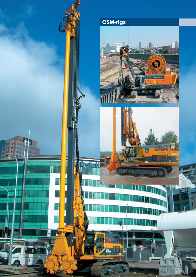
CSM-rigs
905-656-X_08-10_CSM.qxd 05.08.2010 14:32 Uhr Seite 8
9
© BAUER Maschinen GmbH, 8/2010 CSM Cutter Soil Mixing
2800
B
600340
BCM 10
2400
B
600340
BCM 5
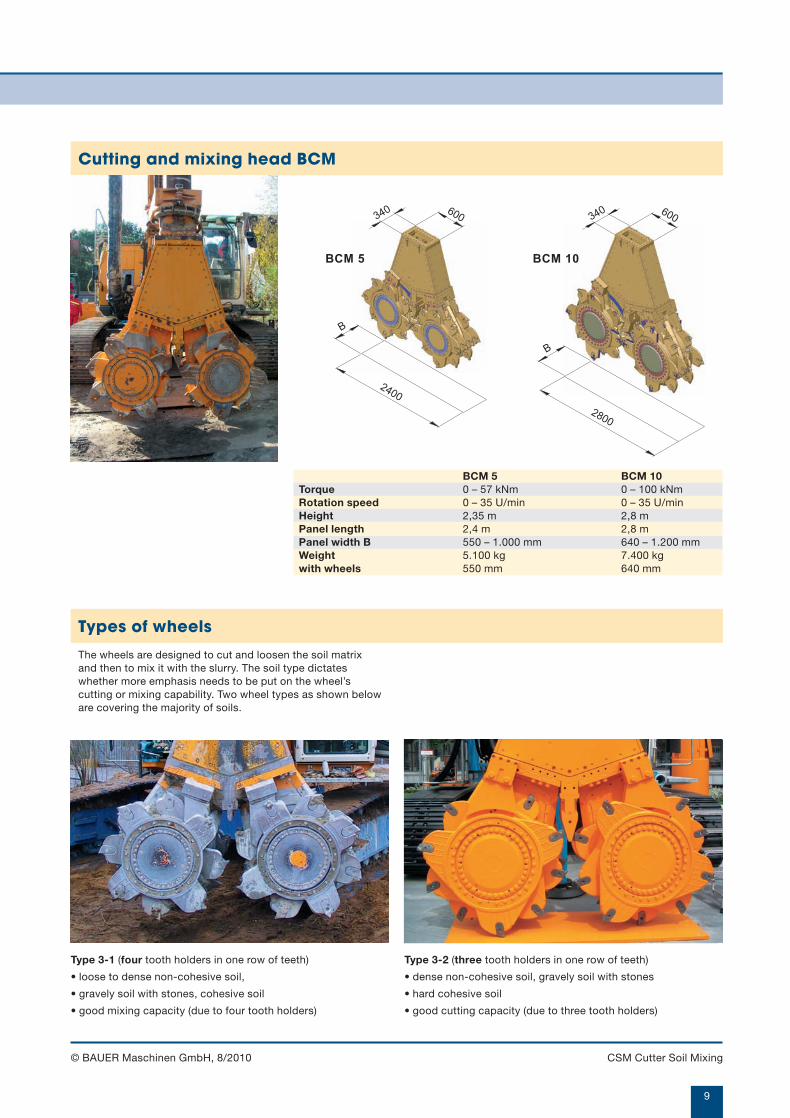
BCM 5 BCM 10Torque 0 – 57 kNm 0 – 100 kNmRotation speed 0 – 35 U/min 0 – 35 U/minHeight 2,35 m 2,8 mPanel length 2,4 m 2,8 mPanel width B 550 – 1.000 mm 640 – 1.200 mmWeight 5.100 kg 7.400 kgwith wheels 550 mm 640 mm
Type 3-1 (four tooth holders in one row of teeth)
• loose to dense non-cohesive soil,
• gravely soil with stones, cohesive soil
• good mixing capacity (due to four tooth holders)
Type 3-2 (three tooth holders in one row of teeth)
• dense non-cohesive soil, gravely soil with stones
• hard cohesive soil
• good cutting capacity (due to three tooth holders)
Types of wheels
The wheels are designed to cut and loosen the soil matrixand then to mix it with the slurry. The soil type dictateswhether more emphasis needs to be put on the wheel’scutting or mixing capability. Two wheel types as shown beloware covering the majority of soils.
Cutting and mixing head BCM
905-656-X_08-10_CSM.qxd 05.08.2010 14:32 Uhr Seite 9
10
CSM Cutter Soil Mixing © BAUER Maschinen GmbH, 8/2010
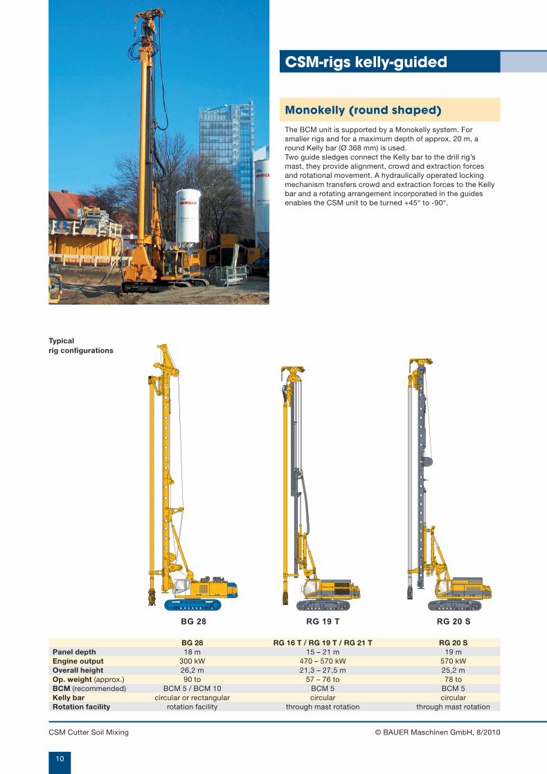
RG 20 SRG 19 TBG 28
CSM-rigs kelly-guided
BG 28 RG 16 T / RG 19 T / RG 21 T RG 20 SPanel depth 18 m 15 – 21 m 19 mEngine output 300 kW 470 – 570 kW 570 kWOverall height 26,2 m 21,3 – 27,5 m 25,2 mOp. weight (approx.) 90 to 57 – 76 to 78 toBCM (recommended) BCM 5 / BCM 10 BCM 5 BCM 5Kelly bar circular or rectangular circular circularRotation facility rotation facility through mast rotation through mast rotation
Monokelly (round shaped)
The BCM unit is supported by a Monokelly system. Forsmaller rigs and for a maximum depth of approx. 20 m, around Kelly bar (Ø 368 mm) is used.Two guide sledges connect the Kelly bar to the drill rig’smast, they provide alignment, crowd and extraction forcesand rotational movement. A hydraulically operated lockingmechanism transfers crowd and extraction forces to the Kellybar and a rotating arrangement incorporated in the guidesenables the CSM unit to be turned +45° to -90°.
Typical rig configurations
905-656-X_08-10_CSM.qxd 05.08.2010 14:32 Uhr Seite 10
11
© BAUER Maschinen GmbH, 8/2010 CSM Cutter Soil Mixing
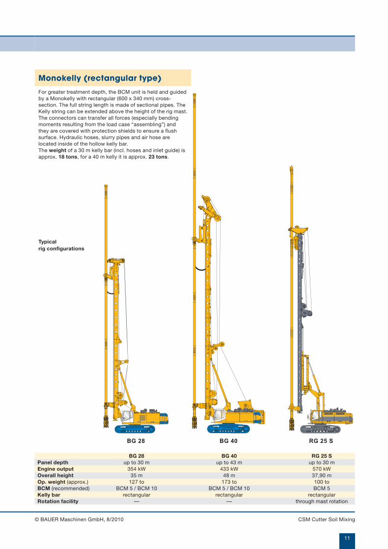
RG 25 SBG 40BG 28
BG 28 BG 40 RG 25 SPanel depth up to 30 m up to 43 m up to 30 mEngine output 354 kW 433 kW 570 kWOverall height 35 m 48 m 37,90 mOp. weight (approx.) 127 to 173 to 100 toBCM (recommended) BCM 5 / BCM 10 BCM 5 / BCM 10 BCM 5Kelly bar rectangular rectangular rectangularRotation facility –– –– through mast rotation
Monokelly (rectangular type)
For greater treatment depth, the BCM unit is held and guidedby a Monokelly with rectangular (600 x 340 mm) cross-section. The full string length is made of sectional pipes. TheKelly string can be extended above the height of the rig mast.The connectors can transfer all forces (especially bendingmoments resulting from the load case “assembling”) andthey are covered with protection shields to ensure a flushsurface. Hydraulic hoses, slurry pipes and air hose arelocated inside of the hollow kelly bar.The weight of a 30 m kelly bar (incl. hoses and inlet guide) isapprox. 18 tons, for a 40 m kelly it is approx. 23 tons.
Typical rig configurations
905-656-X_08-10_CSM.qxd 05.08.2010 14:32 Uhr Seite 11

12
CSM Cutter Soil Mixing © BAUER Maschinen GmbH, 8/2010
x
y
MC 64BG 28
BG 28 BG 40 MC 64Panel depth 38 m 48 m 50 mEngine output 300 kW 433 kW 447 kWOverall height 26,5 m 27 m 33 mOp. weight (approx.) 85 to 130 to 120 toHose handling system HSS HSS HTSBCM (recommended) BCM 5 / BCM 10 BCM 5 / BCM 10 BCM 5 / BCM 10
with guide frame
For constructing deep panels, the mixing head BCM 5 and BCM 10 can be mountedat the bottom of a wire rope suspended guide frame (overall height 9 m). Forstabilising the unit side plates of the frame are extended during lowering of the unit(left picture). They are retracted during extraction of the unit for minimizing frictionresistance in the mixed panel (right picture). For verticality control in x-direction the rotation speed of the wheels can be varied.For controlling the y-direction the inner frame can be tilted relative to the outerframe.
The unit can be mounted on a BG rig or on a crawler crane.Before mounting the system on a standard crawler crane, the suitability of the basecrane has to be checked and confirmed.
CSM-rigs, wire rope suspended
905-656-X_08-10_CSM.qxd 05.08.2010 14:33 Uhr Seite 12

13
© BAUER Maschinen GmbH, 8/2010 CSM Cutter Soil Mixing
QuattroCutter SideCutterPanel depth 60 m 60 mEngine output 2 x 260 kW 2 x 260 kWOverall height 4,8 m 8,6 mOp. weight (approx.) 85 to 90 toWorking width 8,0 – 9,0 m 4,5 m
QuattroCutter
The “QuattroCutter” is a new development for CSM SoilMixing. It is formed of a frame and of two BCM 5 units (one atthe bottom and one at the top of the frame. The arrangementof two mixing heads ensures an intensive and homogeneousmixing as well as a high directional accuracy for big depth.The hydraulic hoses and the wire ropes are mounted on onehose winding drum.The QuattroCutter is suitable for a maximum panel depth of60 m even for works in limited height conditions of 5 m.
SideCutter
The SideCutter is a further development of theQuattroCutters. Due to ist turnable superstructure it allows aminimum working width of only 4,5 m.
905-656-X_08-10_CSM.qxd 05.08.2010 14:33 Uhr Seite 13

14
CSM Cutter Soil Mixing © BAUER Maschinen GmbH, 8/2010
The list is intended as a guide for auxiliary equipment toensure an efficient working sequence.
Auxiliary equipmentFor one-phase and two-phaseworking sequence:• Slurry mixing station
minimum capacity 20 m3/h
• Delivery pumpfrequency controlled slurry pump with remote control, capacitydepends on volume of panel and speed of mixing.(typically: 200 – 600 l/min, 12 – 15 bar)
• Agitator tankapprox. 3 – 5 m3 (as buffer for cement slurry)
• Silosfor cement and bentonite with screw conveyors
• Hydraulic backhoefor excavation of guide trench, maintenance of workingplatform, handling of backflow
• Hosesfor conveying cement or bentonite slurry from the agitator tothe rig. Typically 1,5” or 2” rubber hose (length to suit siterequirements)
• Air compressor – recommended 7 – 14 bar / 7 – 10 m3/min (for air assisted mixing)
• Service crane and vibrator – optionalfor inserting universal beams or other reinforcement into thepanel of retaining wall. Size of crane depends on length andweight of beams and vibrator use.
additionally for two-phase workingsequence:• Agitator tank
as buffer for bentonite slurry
• Delivery pump – optionalpumping of reflux slurry from trench to desanding plant
• Scratching belt – optionaltransporting of reflux slurry from trench to primary desandingplant
• Desanding plant – optionalfor separating soil out of the reflux slurry
• Mobile sieve unit – optionallocated near the trench for pre-screening dense reflux slurry
Mobile sieve unit
Mixing station
Scratching beltIt is placed on top of the trench, immerging into the trench andconveying the bentonite/soil mixture automatically upwards intoa dewatering screen. The fully automated process does notrequire any additional workforce.
Combined mixing and pumping station
905-656-X_08-10_CSM.qxd 05.08.2010 14:33 Uhr Seite 14

15
© BAUER Maschinen GmbH, 8/2010 CSM Cutter Soil Mixing
Control of production parameters (displayed on the monitor of the rig operator)
An electronic monitoring and control system – B-Tronic – can be installed in all CSM rigs. This data acquisition systemmonitors and controls construction parameters as well asgeneral rig functions.
Production data as listed below are continuously acquired,visualised and stored.• Depth
• Volume
• Slurry pressure in hoses
• Slurry-soil pressure in trench
• Pumped volume vs. time
• Pumped volume vs. depth
• Inclination (in two directions)
• Speed of mixing tool
• General rig parameters
Quality control
DocumentationAll production parameters aremonitored, recorded and stored insidethe rig throughout the constructionprocess and can be printed out in theform of a quality assurance record foreach individual panel.
905-656-X_08-10_CSM.qxd 05.08.2010 14:33 Uhr Seite 15
BAUER Maschinen GmbHBAUER-Straße 1D-86529 SchrobenhausenTel. +49 (0)82 52/97-0Fax +49 (0)82 52/97-1135e-mail: [email protected]
Design developments and process improvements may require thespecification and materials to be updated and changed withoutprior notice or liability. Illustrations may include optional equipmentand not show all possible configurations. These and the technical data are provided as indicative informationonly, with any errors and misprints reserved.
905.656.2 8/10
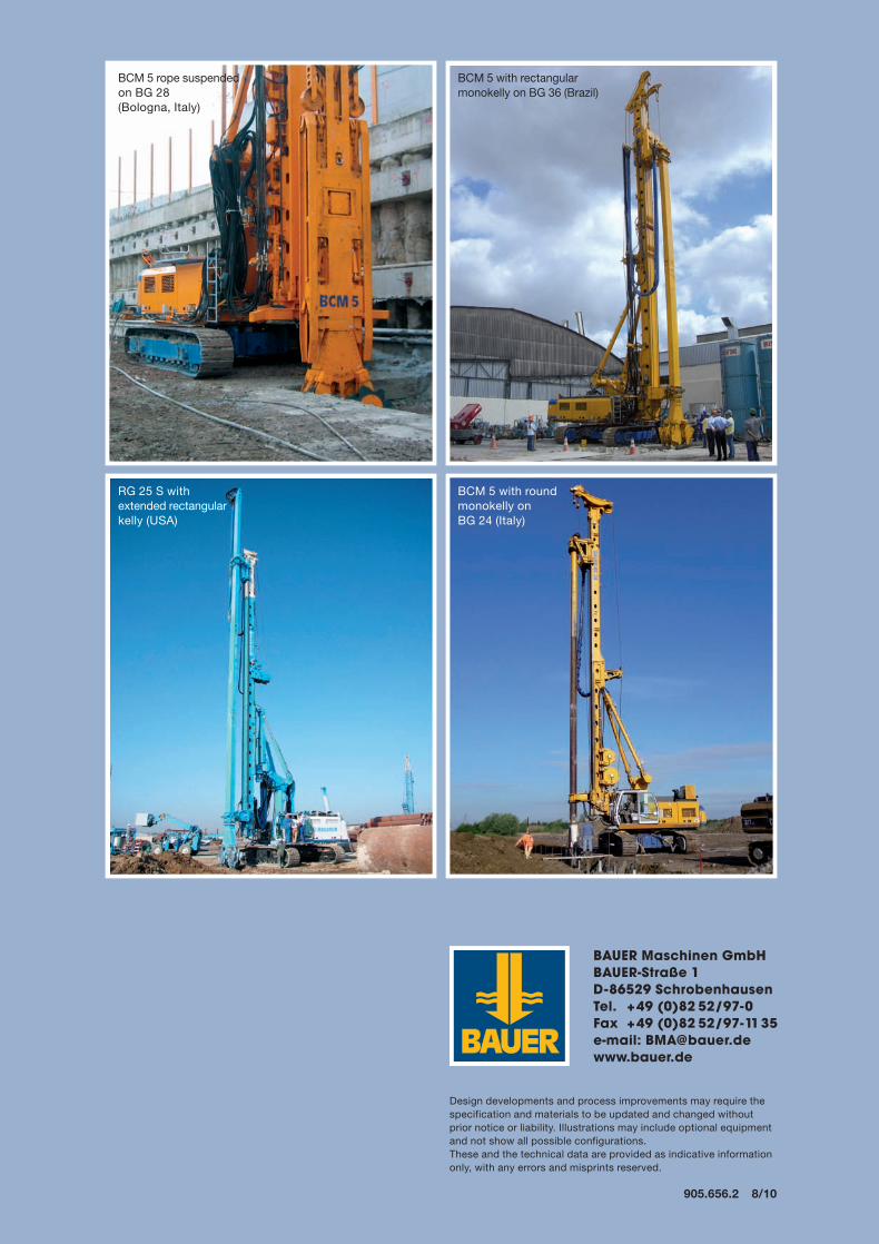
BCM 5 rope suspended on BG 28 (Bologna, Italy)
BCM 5 with rectangular monokelly on BG 36 (Brazil)
RG 25 S with extended rectangular kelly (USA)
BCM 5 with round monokelly on BG 24 (Italy)
905-656-X_08-10_CSM.qxd 05.08.2010 14:34 Uhr Seite 16