900 SERIES - Blodgett
22
900 SERIES ROASTING, BAKING AND PIZZA OVEN INSTALLATION - OPERATION - MAINTENANCE BLODGETT OVEN COMPANY www.blodgett.com 44 Lakeside Avenue, Burlington, Vermont 05401 USA Telephone: (802) 658-6600 Fax: (802)864-0183 PN 11356 Rev L (11/17) © 2017 - G.S. Blodgett Corporation
Transcript of 900 SERIES - Blodgett
900 SERIESROASTING, BAKING AND PIZZA OVEN
INSTALLATION - OPERATION - MAINTENANCE
BLODGETT OVEN COMPANYwww.blodgett.com
44 Lakeside Avenue, Burlington, Vermont 05401 USA Telephone: (802) 658-6600 Fax: (802)864-0183PN 11356 Rev L (11/17)
© 2017 - G.S. Blodgett Corporation
Your Service Agency’s Address:Model
Serial number
Oven installed by
Installation checked by
TABLE OF CONTENTS
INSTALLATIONOven Description and Specifications . . . . . . . . . . . . . . . . . . . . . . . . . . . . . . . . . . . . . . . 2Delivery and Location . . . . . . . . . . . . . . . . . . . . . . . . . . . . . . . . . . . . . . . . . . . . . . . . . . . . 4Oven Assembly . . . . . . . . . . . . . . . . . . . . . . . . . . . . . . . . . . . . . . . . . . . . . . . . . . . . . . . . . . 5
Packaging . . . . . . . . . . . . . . . . . . . . . . . . . . . . . . . . . . . . . . . . . . . . . . . . . . . . . . . . . . . 5Leg Attachment . . . . . . . . . . . . . . . . . . . . . . . . . . . . . . . . . . . . . . . . . . . . . . . . . . . . . . 5Caster Attachment . . . . . . . . . . . . . . . . . . . . . . . . . . . . . . . . . . . . . . . . . . . . . . . . . . . . 5Double Section Assembly . . . . . . . . . . . . . . . . . . . . . . . . . . . . . . . . . . . . . . . . . . . . . 6Ultra Rokite Deck . . . . . . . . . . . . . . . . . . . . . . . . . . . . . . . . . . . . . . . . . . . . . . . . . . . . 6
Steam Injection . . . . . . . . . . . . . . . . . . . . . . . . . . . . . . . . . . . . . . . . . . . . . . . . . . . . . . . . . . 7Ventilation . . . . . . . . . . . . . . . . . . . . . . . . . . . . . . . . . . . . . . . . . . . . . . . . . . . . . . . . . . . . . . . 8Utility Connections - Standards and Codes . . . . . . . . . . . . . . . . . . . . . . . . . . . . . . . . 10Gas Connection. . . . . . . . . . . . . . . . . . . . . . . . . . . . . . . . . . . . . . . . . . . . . . . . . . . . . . . . . 11
Gas Piping. . . . . . . . . . . . . . . . . . . . . . . . . . . . . . . . . . . . . . . . . . . . . . . . . . . . . . . . . . 11Pressure Regulation and Testing . . . . . . . . . . . . . . . . . . . . . . . . . . . . . . . . . . . . . . 12Gas Hose Restraint . . . . . . . . . . . . . . . . . . . . . . . . . . . . . . . . . . . . . . . . . . . . . . . . . 13
Initial Startup . . . . . . . . . . . . . . . . . . . . . . . . . . . . . . . . . . . . . . . . . . . . . . . . . . . . . . . . . . . 14
OPERATIONSafety Information . . . . . . . . . . . . . . . . . . . . . . . . . . . . . . . . . . . . . . . . . . . . . . . . . . . . . . . 15Oven Control . . . . . . . . . . . . . . . . . . . . . . . . . . . . . . . . . . . . . . . . . . . . . . . . . . . . . . . . . . . 16Suggested Times and Temperatures . . . . . . . . . . . . . . . . . . . . . . . . . . . . . . . . . . . . . . 17
MAINTENANCECleaning and Preventative Maintenance . . . . . . . . . . . . . . . . . . . . . . . . . . . . . . . . . . 19Troubleshooting Guide . . . . . . . . . . . . . . . . . . . . . . . . . . . . . . . . . . . . . . . . . . . . . . . . . . 20
IMPORTANT WARNING: Improper installa-tion, adjustment, alternation, service or maintenance can cause property damage, in-jury or death. Read the instl-lation, operation and mainte-nance instructions thoroughly before installing or servicing this equipment.
INSTRUCTIONS TO BE FOL-LOWED IN THE EVENT THE USER SMELLS GAS MUST BE POSTED IN A PROMINENT LO-CATION. This information may be obtained by contacting your local gas supplier.
FOR YOUR SAFETY
Do not store or use gasoline or other flammable vapors or liq-uids in the vicinity of this or any other appliance.
The information contained in this manual is important for the prop-er installation, use, and mainte-nance of this oven. Adherence to these procedures and instruc-tions will result in satisfactory baking results and long, trou-ble free service. Please read this manual carefully and retain it for future reference.
ERRORS: Descriptive, typo-graphic or pictorial errors are subject to correction. Specifi-cations are subject to change without notice.
2
InstallationOven Description and Specifications
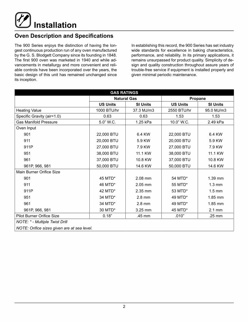
GAS RATINGSNatural Gas Propane
US Units SI Units US Units SI UnitsHeating Value 1000 BTU/hr 37.3 MJ/m3 2550 BTU/hr 95.0 MJ/m3Specific Gravity (air=1.0) 0.63 0.63 1.53 1.53Gas Manifold Pressure 5.0” W.C. 1.25 kPa 10.0” W.C. 2.49 kPaOven Input
901911911P951961961P, 966, 981
22,000 BTU20,000 BTU27,000 BTU38,000 BTU37,000 BTU50,000 BTU
6.4 KW5.9 KW7.9 KW11.1 KW10.8 KW14.6 KW
22,000 BTU20,000 BTU27,000 BTU38,000 BTU37,000 BTU50,000 BTU
6.4 KW5.9 KW7.9 KW11.1 KW10.8 KW14.6 KW
Main Burner Orifice Size901911911P951961961P, 966, 981
45 MTD*46 MTD*42 MTD*34 MTD*34 MTD*30 MTD*
2.08 mm2.05 mm2.35 mm2.8 mm2.8 mm3.25 mm
54 MTD*55 MTD*53 MTD*49 MTD*49 MTD*45 MTD*
1.39 mm1.3 mm1.5 mm
1.85 mm1.85 mm2.1 mm
Pilot Burner Orifice Size 0.18” .45 mm .010” .25 mmNOTE: * - Multiple Twist DrillNOTE: Orifice sizes given are at sea level.
The 900 Series enjoys the distinction of having the lon-gest continuous production run of any oven manufactured by the G. S. Blodgett Company since its founding in 1848. The first 900 oven was marketed in 1940 and while ad-vancements in metallurgy and more convenient and reli-able controls have been incorporated over the years, the basic design of this unit has remained unchanged since its inception.
In establishing this record, the 900 Series has set industry wide standards for excellence in baking characteristics, performance, and reliability. In its primary applications, it remains unsurpassed for product quality. Simplicity of de-sign and quality construction throughout assure years of trouble-free service if equipment is installed properly and given minimal periodic maintenance.
3
InstallationOven Description and Specifications
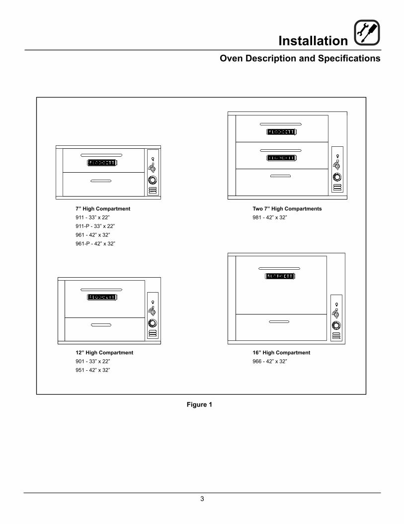
Figure 1
7” High Compartment911 - 33” x 22”911-P - 33” x 22”961 - 42” x 32”961-P - 42” x 32”
Two 7” High Compartments981 - 42” x 32”
12” High Compartment901 - 33” x 22”951 - 42” x 32”
16” High Compartment966 - 42” x 32”

4
InstallationDelivery and LocationDELIVERY AND INSPECTIONAll Blodgett ovens are shipped in containers to prevent damage. Upon delivery of your new oven: • Inspect the shipping container for external damage.
Any evidence of damage should be noted on the delivery receipt which must be signed by the driver.
• Uncrate the oven and check for internal damage. Carriers will accept claims for concealed damage if notified within fifteen days of delivery and the ship-ping container is retained for inspection.
The Blodgett Oven Company cannot assume responsibil-ity for loss or damage suffered in transit. The carrier as-sumed full responsibility for delivery in good order when the shipment was accepted. We are, however, prepared to assist you if filing a claim is necessary.
OVEN LOCATIONThe well planned and proper placement of your oven will result in long term operator convenience and satisfactory performance. The following clearances must be maintained between the oven and any combustible or non-combustible con-struction.• Oven body right side - 6” (15cm)
• Oven body left side - 6” (15cm)
• Oven body back - 6” (15cm)
• Single and stacked oven bottom - 6” (15cm)
Area must be accessible for proper servicing.NOTE: On gas models, routine servicing can usually be
accomplished within the limited movement pro-vided by the gas hose restraint. If the oven needs to be moved further from the wall, the gas must first be turned off and disconnected from the oven before removing the restraint. Reconnect the re-straint after the oven has been returned to its nor-mal position.
It is essential that an adequate air supply to the oven be maintained to provide a sufficient flow of combustion and ventilation air.• Place the oven in an area that is free of drafts.
• Keep the oven area free and clear of all combus-tibles such as paper, cardboard, and flammable liquids and solvents.
• Do not place the oven on a curb base or seal to a wall. Either condition will restrict the proper flow of combustion and ventilation air resulting in damage to the oven.
5
InstallationOven Assembly
PACKAGINGBefore beginning assembly of the oven, check for all nec-essary components. In addition to the oven itself, legs, a proper vent, and/or other accessories may be required.900 Series ovens are packaged as follows:Single Section OvensThe following are packed in the oven:• A set of 27-1/2” (70 cm) legs with attaching hard-
ware.
• Either a canopy or direct vent as specified
• Either a natural gas or propane gas pressure regula-tor as required.
Multiple Section OvensThe following are packed inside the bottom section:• A set of legs of the appropriate length
• Either a canopy or direct vent as specified
• A back pipe of appropriate length with either a natu-ral gas or propane gas regulator attached
Additional Packaging• Ultra Rokite decks for all 900 Series are packed in a
separate crate.
• The top section of multiple section ovens will always have the crown angle in position.
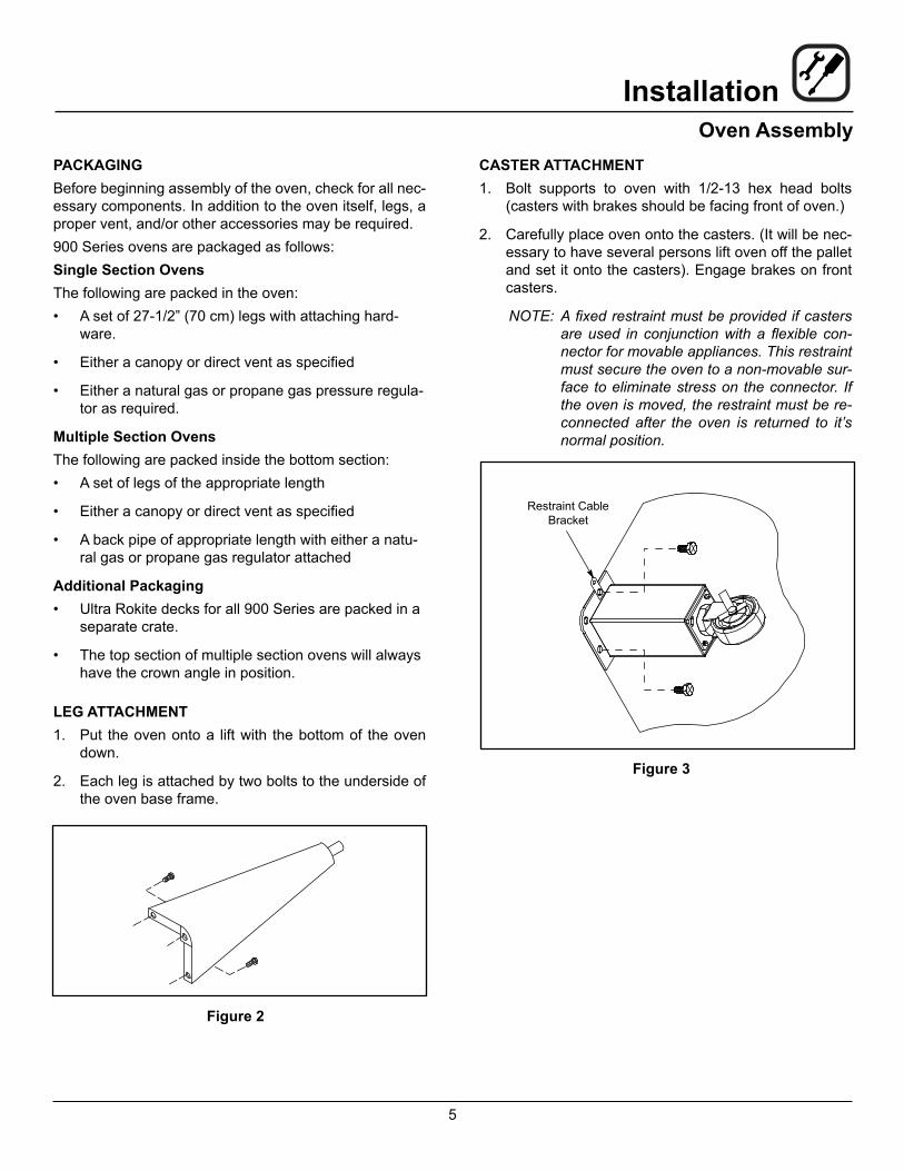
LEG ATTACHMENT1. Put the oven onto a lift with the bottom of the oven
down.
2. Each leg is attached by two bolts to the underside of the oven base frame.
Figure 2
CASTER ATTACHMENT1. Bolt supports to oven with 1/2-13 hex head bolts
(casters with brakes should be facing front of oven.)
2. Carefully place oven onto the casters. (It will be nec-essary to have several persons lift oven off the pallet and set it onto the casters). Engage brakes on front casters.
NOTE: A fixed restraint must be provided if casters are used in conjunction with a flexible con-nector for movable appliances. This restraint must secure the oven to a non-movable sur-face to eliminate stress on the connector. If the oven is moved, the restraint must be re-connected after the oven is returned to it’s normal position.
Restraint Cable Bracket
Figure 3
6
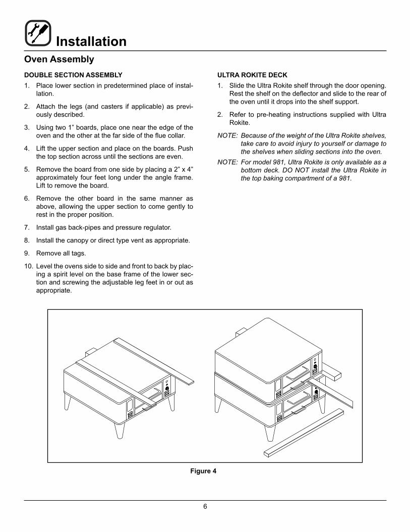
InstallationOven AssemblyDOUBLE SECTION ASSEMBLY1. Place lower section in predetermined place of instal-
lation.
2. Attach the legs (and casters if applicable) as previ-ously described.
3. Using two 1” boards, place one near the edge of the oven and the other at the far side of the flue collar.
4. Lift the upper section and place on the boards. Push the top section across until the sections are even.
5. Remove the board from one side by placing a 2” x 4” approximately four feet long under the angle frame. Lift to remove the board.
6. Remove the other board in the same manner as above, allowing the upper section to come gently to rest in the proper position.
7. Install gas back-pipes and pressure regulator.
8. Install the canopy or direct type vent as appropriate.
9. Remove all tags.
10. Level the ovens side to side and front to back by plac-ing a spirit level on the base frame of the lower sec-tion and screwing the adjustable leg feet in or out as appropriate.
ULTRA ROKITE DECK1. Slide the Ultra Rokite shelf through the door opening.
Rest the shelf on the deflector and slide to the rear of the oven until it drops into the shelf support.
2. Refer to pre-heating instructions supplied with Ultra Rokite.
NOTE: Because of the weight of the Ultra Rokite shelves, take care to avoid injury to yourself or damage to the shelves when sliding sections into the oven.
NOTE: For model 981, Ultra Rokite is only available as a bottom deck. DO NOT install the Ultra Rokite in the top baking compartment of a 981.
Figure 4
7
InstallationOven Assembly
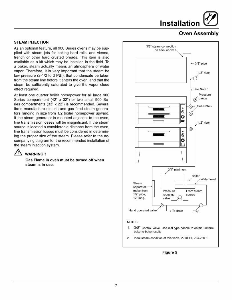
STEAM INJECTIONAs an optional feature, all 900 Series ovens may be sup-plied with steam jets for baking hard rolls, and vienna, french or other hard crusted breads. This item is also available as a kit which may be installed in the field. To a baker, steam actually means an atmosphere of water vapor. Therefore, it is very important that the steam be low pressure (2-1/2 to 3 PSI), that condensate be taken from the steam line before it enters the oven, and that the steam be sufficiently saturated to give the vapor cloud effect required.At least one quarter boiler horsepower for all large 900 Series compartment (42” x 32”) or two small 900 Se-ries compartments (33” x 22”) is recommended. Several firms manufacture electric and gas fired steam genera-tors ranging in size from 1/2 boiler horsepower upward. If the steam generator is mounted adjacent to the oven, line transmission losses will be insignificant. If the steam source is located a considerable distance from the oven, line transmission losses must be considered in determin-ing the proper size of the steam. Please refer to the ac-companying diagram for the recommended installation of the steam injection system.
WARNING!!Gas Flame in oven must be turned off when steam is in use.
Figure 5
3/8” steam connection on back of oven
3/8” pipe
1/2” riser
See Note 1
Pressure gauge
See Note 2
1/2” riser
Steam separator, make from 1/2” pipe, 12” long.
3/4” minimum
BoilerWater level
Pressure reducing valve
From steam source
Hand operated valve To drain Trap
NOTES:
1. 3/8” Control Valve. Use dial type handle to obtain uniform bake-to-bake results
2. Ideal steam condition at this valve, 2-3#PSI, 224-230 F.
8
InstallationVentilationBlodgett gas deck ovens are direct fired. Heat and flue products from the burners are introduced directly into the baking compartment. As a result, improper venting can have a detrimental effect on the baking characteristics of the oven. A properly designed ventilation system will allow the oven to function properly, while removing un-wanted vapors and products of combustion from the op-erating area.This oven may be vented using either:• A mechanically driven, canopy type, exhaust hood,
or
• A direct flue arrangement.
U.S. and Canadian installationsRefer to your local ventilation codes. In the absence of local codes, refer to the National ventilation code titled, “Standard for the Installation of Equipment for the Remov-al of Smoke and Grease Laden Vapors from Commercial Cooking Equipment”, NFPA-96-Latest Edition.General export installationsInstallation must conform with Local and National instal-lation standards. Local installation codes and/or require-ments may vary. If you have any questions regarding the proper installation and/or operation of your Blodgett oven, please contact your local distributor. If you do not have a local distributor, please call the Blodgett Oven Company at 0011-802-658-6600.The Blodgett Oven Company cannot assume responsi-bility for loss or damage suffered as a result of improper installation..
WARNING:Failure to properly vent the oven can be haz-ardous to the health of the operator and may result in operational problems, unsatisfactory baking and possible damage to the equip-ment.Damage sustained as a direct result of im-proper ventilation will not be covered by the Manufacturer’s warranty.
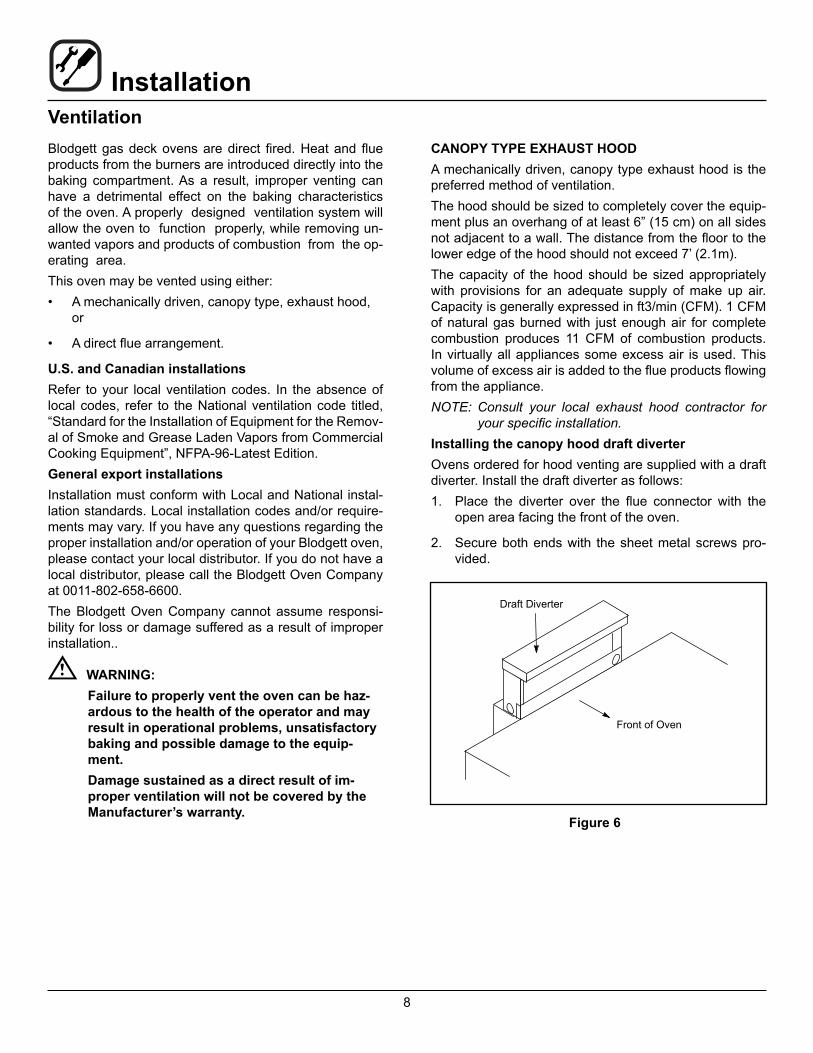
CANOPY TYPE EXHAUST HOODA mechanically driven, canopy type exhaust hood is the preferred method of ventilation.The hood should be sized to completely cover the equip-ment plus an overhang of at least 6” (15 cm) on all sides not adjacent to a wall. The distance from the floor to the lower edge of the hood should not exceed 7’ (2.1m).The capacity of the hood should be sized appropriately with provisions for an adequate supply of make up air. Capacity is generally expressed in ft3/min (CFM). 1 CFM of natural gas burned with just enough air for complete combustion produces 11 CFM of combustion products. In virtually all appliances some excess air is used. This volume of excess air is added to the flue products flowing from the appliance.NOTE: Consult your local exhaust hood contractor for
your specific installation.Installing the canopy hood draft diverterOvens ordered for hood venting are supplied with a draft diverter. Install the draft diverter as follows:1. Place the diverter over the flue connector with the
open area facing the front of the oven.
2. Secure both ends with the sheet metal screws pro-vided.
Draft Diverter
Front of Oven
Figure 6
9
InstallationVentilation
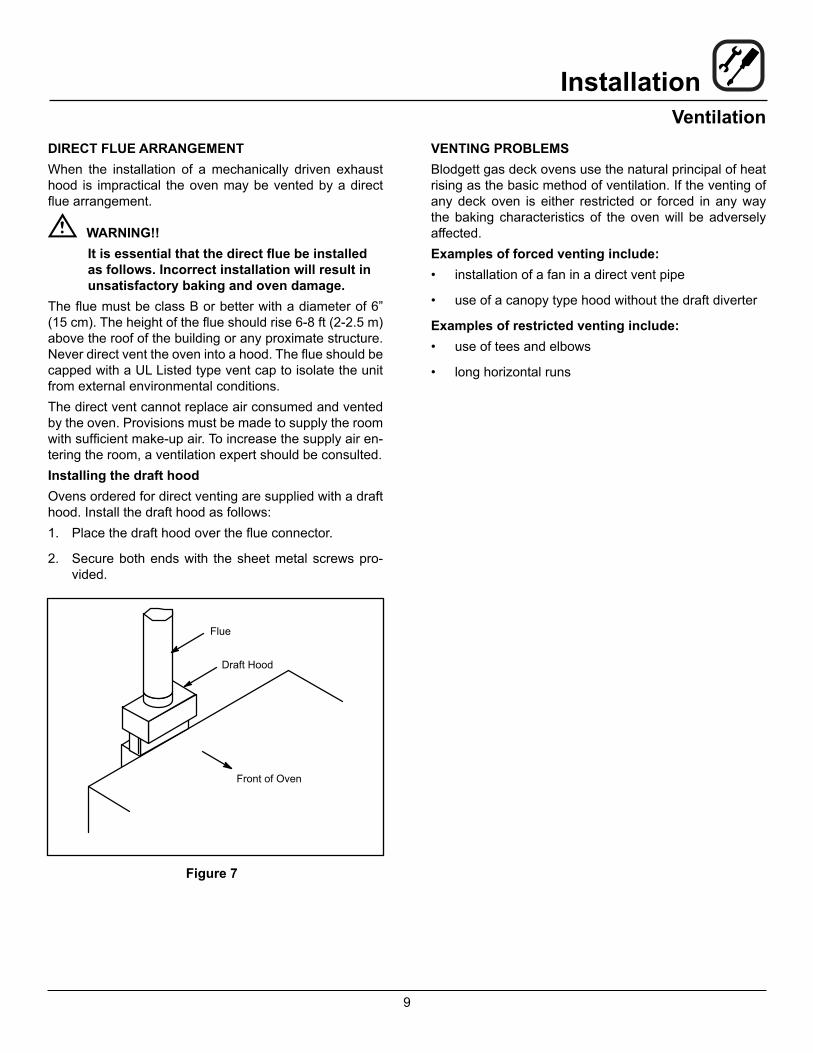
DIRECT FLUE ARRANGEMENTWhen the installation of a mechanically driven exhaust hood is impractical the oven may be vented by a direct flue arrangement.
WARNING!!It is essential that the direct flue be installed as follows. Incorrect installation will result in unsatisfactory baking and oven damage.
The flue must be class B or better with a diameter of 6” (15 cm). The height of the flue should rise 6-8 ft (2-2.5 m) above the roof of the building or any proximate structure. Never direct vent the oven into a hood. The flue should be capped with a UL Listed type vent cap to isolate the unit from external environmental conditions.The direct vent cannot replace air consumed and vented by the oven. Provisions must be made to supply the room with sufficient make-up air. To increase the supply air en-tering the room, a ventilation expert should be consulted.Installing the draft hoodOvens ordered for direct venting are supplied with a draft hood. Install the draft hood as follows:1. Place the draft hood over the flue connector.
2. Secure both ends with the sheet metal screws pro-vided.
Flue
Draft Hood
Front of Oven
Figure 7
VENTING PROBLEMSBlodgett gas deck ovens use the natural principal of heat rising as the basic method of ventilation. If the venting of any deck oven is either restricted or forced in any way the baking characteristics of the oven will be adversely affected.Examples of forced venting include:• installation of a fan in a direct vent pipe
• use of a canopy type hood without the draft diverter
Examples of restricted venting include:• use of tees and elbows
• long horizontal runs

10
InstallationUtility Connections - Standards and CodesTHE INSTALLATION INSTRUCTIONS CONTAINED HEREIN ARE FOR THE USE OF QUALIFIED INSTAL-LATION AND SERVICE PERSONNEL ONLY. INSTAL-LATION OR SERVICE BY OTHER THAN QUALIFIED PERSONNEL MAY RESULT IN DAMAGE TO THE OVEN AND/OR INJURY TO THE OPERATOR.Qualified installation personnel are individuals, a firm, a corporation, or a company which either in person or through a representative are engaged in, and responsible for:• the installation or replacement of gas piping and the
connection, installation, repair or servicing of equip-ment.
• the installation of electrical wiring from the electric meter, main control box or service outlet to the elec-tric appliance.
Qualified installation personnel must be experienced in such work, familiar with all precautions required, and have complied with all requirements of state or local authorities having jurisdiction.
U.S. and Canadian installationsThe installation must conform with local codes, or in the absence of local codes, with the National Fuel Gas Code, ANSI Z223.1/NFPA 54, or the Natural Gas and Propane Installation Code, CSA B149.1, as applicable.Installation must conform with local codes, or in the ab-sence of local codes, with the National Electrical Code, ANSI/NFPA 70-Latest Edition and/or Canadian National Electric Code C22.1 as applicable.Appliance is to be installed with backflow prevention in accordance with applicable federal, province and local codes.Australia and general export installationsInstllation must conform with Local and National instal-lation standards. Local installation codes and/or require-ments may vary. If you have any questions regarding the proper installation and/or operation of your Blodgett oven, please contact your local distributor. If you do not have a local distributor, please call the Blodgett Oven Company at 0011-802-658-6600.
11
InstallationGas Connection
GAS PIPINGA properly sized gas supply system is essential for maxi-mum oven performance. Piping should be sized to pro-vide a supply of gas sufficient to meet the maximum de-mand of all appliances on the line without loss of pressure at the equipment.Example:NOTE: BTU values in the following example are for natu-
ral gas.You purchase a Model 911 deck oven to add to your exist-ing cook line.1. Add the BTU rating of your current appliances.
Pitco Fryer 120,000 BTU6 Burner Range 60,000 BTUDeck Oven 50,000 BTUTotal 230,000 BTU
2. Add the BTU rating of the new oven to the total.
Previous Total 230,000 BTU911 20,000 BTUNew Total 250,000 BTU
3. Measure the distance from the gas meter to the cook line. This is the pipe length. Let’s say the pipe length is 40’ (12.2 m) and the pipe size is 1” (2.54 cm).
4. Use the appropriate table to determine the total ca-pacity of your current gas piping.
The total capacity for this example is 320,000 BTU. Since the total required gas pressure, 250,000 BTU is less than 320,000 BTU, the current gas piping will not have to be increased.
NOTE: The BTU capacities given in the tables are for straight pipe lengths only. Any elbows or other fittings will decrease pipe capacities. Contact your local gas supplier if you have any questions.
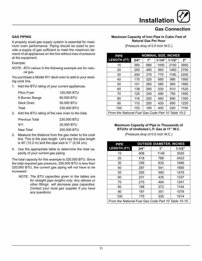
Maximum Capacity of Iron Pipe in Cubic Feet of Natural Gas Per Hour
(Pressure drop of 0.5 Inch W.C.)
PIPE LENGTH (FT)
NOMINAL SIZE, INCHES3/4” 1” 1-1/4” 1-1/2” 2”
10 360 680 1400 2100 395020 250 465 950 1460 275030 200 375 770 1180 220040 170 320 660 990 190050 151 285 580 900 168060 138 260 530 810 152070 125 240 490 750 140080 118 220 460 690 130090 110 205 430 650 1220
100 103 195 400 620 1150From the National Fuel Gas Code Part 10 Table 10-2
Maximum Capacity of Pipe in Thousands of BTU/hr of Undiluted L.P. Gas at 11” W.C.
(Pressure drop of 0.5 Inch W.C.)
PIPE LENGTH (FT)
OUTSIDE DIAMETER, INCHES3/4” 1” 1-1/2”
10 608 1146 352520 418 788 242330 336 632 194640 287 541 166550 255 480 147660 231 435 133770 215 404 124180 198 372 114490 187 351 1079100 175 330 1014
From the National Fuel Gas Code Part 10 Table 10-15

12
InstallationGas ConnectionPRESSURE REGULATION AND TESTING900 Series ovens are rated from 20,000 to 50,000 BTU/Hr. (6.4 to 14.6 kW/Hr.) per section. Each oven has been adjusted at the factory to operate with the type of gas specified on the rating plate.1. Pull out control panel. The rating plate is attached to
the inside of the control compartment.
INLET PRESSURENatural Propane
Min Max Min MaxW.C. 7.0 10.5 11.0 13.0kPa 1.43 2.61 2.74 3.23
MANIFOLD PRESSURENatural Propane
W.C. 5.0 10.0kPa 1.24 2.49
• Inlet Pressure - the pressure of the gas before it reaches the oven.
• Manifold Pressure - the pressure of the gas as it enters the main burner(s).
• Min - the minimum pressure recommended to oper-ate the oven.
• Max - the maximum pressure at which the manufac-turer warrants the oven’s operation.
Each oven is supplied with a regulator to maintain the proper gas pressure. The regulator is essential to the proper operation of the oven and must be installed. It is preset to provide the oven with 3.5” W.C. (0.87 kPa) for natural gas and 10.5” W.C. (2.50 kPa) for Propane at the manifold.DO NOT INSTALL AN ADDITIONAL REGULATOR WHERE THE OVEN CONNECTS TO THE GAS SUPPLY.Prior to connecting the oven, gas lines should be thor-oughly purged of all metal filings, shavings, pipe dope, and other debris. After connection, the oven should be checked for correct gas pressure.Installation must conform with local codes, or in the ab-sence of local codes, with the National Fuel Gas Code, NFPA54/ANSI Z223.1-Latest Edition, the Natural Gas In-stallation Code CAN/CGA-B149.1 or the Propane Instal-lation Code, CAN/CGA-B149.2 as applicable.The oven and its individual shutoff valve must be discon-nected from the gas supply piping system during any pressure testing of that system at test pressures in ex-cess of 1/2 psig (3.45kPa).The oven must be isolated from the gas supply piping system by closing its individual manual shutoff valve dur-ing any pressure testing of the gas piping system at test pressures equal or less than 1/2 psig (3.45kPa).
13
InstallationGas Connection
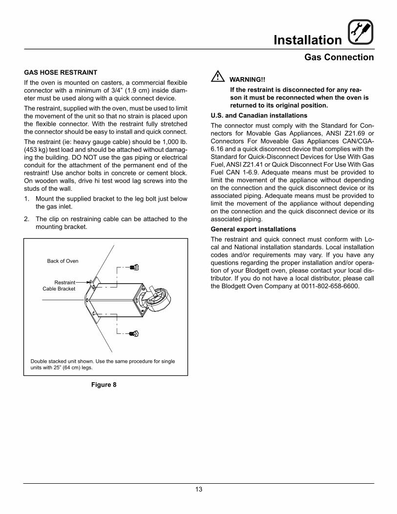
GAS HOSE RESTRAINTIf the oven is mounted on casters, a commercial flexible connector with a minimum of 3/4” (1.9 cm) inside diam-eter must be used along with a quick connect device.The restraint, supplied with the oven, must be used to limit the movement of the unit so that no strain is placed upon the flexible connector. With the restraint fully stretched the connector should be easy to install and quick connect.The restraint (ie: heavy gauge cable) should be 1,000 lb. (453 kg) test load and should be attached without damag-ing the building. DO NOT use the gas piping or electrical conduit for the attachment of the permanent end of the restraint! Use anchor bolts in concrete or cement block. On wooden walls, drive hi test wood lag screws into the studs of the wall.1. Mount the supplied bracket to the leg bolt just below
the gas inlet.
2. The clip on restraining cable can be attached to the mounting bracket.
Back of Oven
Restraint Cable Bracket
Double stacked unit shown. Use the same procedure for single units with 25” (64 cm) legs.
Figure 8
WARNING!!If the restraint is disconnected for any rea-son it must be reconnected when the oven is returned to its original position.
U.S. and Canadian installationsThe connector must comply with the Standard for Con-nectors for Movable Gas Appliances, ANSI Z21.69 or Connectors For Moveable Gas Appliances CAN/CGA-6.16 and a quick disconnect device that complies with the Standard for Quick-Disconnect Devices for Use With Gas Fuel, ANSI Z21.41 or Quick Disconnect For Use With Gas Fuel CAN 1-6.9. Adequate means must be provided to limit the movement of the appliance without depending on the connection and the quick disconnect device or its associated piping. Adequate means must be provided to limit the movement of the appliance without depending on the connection and the quick disconnect device or its associated piping.General export installationsThe restraint and quick connect must conform with Lo-cal and National installation standards. Local installation codes and/or requirements may vary. If you have any questions regarding the proper installation and/or opera-tion of your Blodgett oven, please contact your local dis-tributor. If you do not have a local distributor, please call the Blodgett Oven Company at 0011-802-658-6600.
14
InstallationInitial StartupADJUSTMENTS ASSOCIATED WITH INITIAL INSTAL-LATIONEach oven, and its component parts, have been thorough-ly tested and inspected prior to shipment. However, it is often necessary to further test or adjust the oven as part of a normal and proper installation. These adjustments are the responsibility of the installer, or dealer. Since these adjustments are not considered defects in mate-rial or workmanship, they are not covered by the Original Equipment Warranty. They include, but are not limited to:• calibration of the thermostat
• adjustment of the doors
• burner adjustments
• leveling
• testing of gas pressure
• tightening of fasteners
No installation should be considered complete without proper inspection, and if necessary, adjustment by quali-fied installation or service personnel.
15
OperationSafety Information
The information contained in this section is provided for the use of qualified operating personnel. Qualified operat-ing personnel are those who have carefully read the in-formation contained in this manual, are familiar with the functions of the oven and/or have had previous experi-ence with the operation of the equipment described. Ad-herence to the procedures recommended herein will as-sure the achievement of optimum performance and long, trouble-free service.Please take the time to read the following safety and op-erating instructions. They are the key to the successful operation of your Blodgett oven.
SAFETY TIPSFor your safety read before operating
What to do if you smell gas:• DO NOT try to light any appliance.
• DO NOT touch any electrical switches.
• Use an exterior phone to call your gas supplier im-mediately.
• If you cannot reach your gas supplier, call the fire department.
General safety tips:• DO NOT use tools to turn off the gas control. If the
gas cannot be turned off manually do not try to re-pair it. Call a qualified service technician.
• If the oven needs to be moved for any reason, the gas must be turned off and disconnected from the unit before removing the restraint cable. Reconnect the restraint after the oven has been returned to its original location.
Please take the time to read the following operating in-structions. They are the key to the successful operation of your Blodgett deck oven.
WARNING!!In the event of a loss of pilot, allow a five (5) minute shut off period before attempting to relight the oven.
16
OperationOven Control
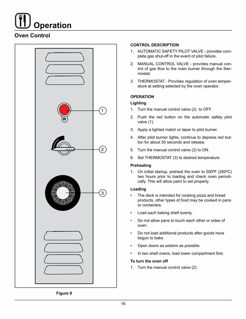
Figure 9
CONTROL DESCRIPTION1. AUTOMATIC SAFETY PILOT VALVE - provides com-
plete gas shut-off in the event of pilot failure.
2. MANUAL CONTROL VALVE - provides manual con-trol of gas flow to the main burner through the ther-mostat.
3. THERMOSTAT - Provides regulation of oven temper-ature at setting selected by the oven operator.
OPERATIONLighting1. Turn the manual control valve (2) to OFF.
2. Push the red button on the automatic safety pilot valve (1).
3. Apply a lighted match or taper to pilot burner.
4. After pilot burner lights, continue to depress red but-ton for about 30 seconds and release.
5. Turn the manual control valve (2) to ON.
6. Set THERMOSTAT (3) to desired temperature.
Preheating1. On initial startup, preheat the oven to 500ºF (260ºC)
two hours prior to loading and check oven periodi-cally. This will allow paint to set properly.
Loading• The deck is intended for cooking pizza and bread
products, other types of food may be cooked in pans or containers.
• Load each baking shelf evenly.
• Do not allow pans to touch each other or sides of oven.
• Do not load additional products after goods have begun to bake.
• Open doors as seldom as possible.
• In two shelf ovens, load lower compartment first.
To turn the oven off1. Turn the manual control valve (2)

17
OperationSuggested Times and Temperatures
PRODUCT TEMPERATURE COOK TIMEMeatsBeefRibs
Rolled, bonelessHip or rump, bonelessVealBone-in cutsBoned cutsLambLeg or shoulderShoulder, bonedPorkFresh bone-in cutsFresh boned cutsHamsBaconSausages, links, pattiesMeat pies, deep dish
325ºF (165ºC)
325ºF (165ºC)325ºF (165ºC)
325ºF (165ºC)325ºF (165ºC)
325ºF (165ºC)325ºF (165ºC)
350ºF (175ºC)350ºF (175ºC)325ºF (165ºC)350ºF (175ºC)350ºF (175ºC)450ºF (230ºC)
rare - 16 mins/lb med - 20 mins/lb well - 25 mins/lb
add 10 mins/lb to above times30 mins/lb
25 mins/lb30 mins/lb
35 mins/lb40 mins/lb
30-40 mins/lb40-50 mins/lb25-30 minss/lb
depends on degree of doneness30 mins/lb
12-15 mins/lbPoultry (Weights are for unstuffed birds, for stuffed, add 15 mins/lb)Chickens, 2-3 lbsChickens, over 5 lbsChicken piesTurkeys, 10-16 lbsTurkeys, 25 lbsDucksGeese
350ºF (175ºC)325ºF (165ºC)450ºF (230ºC)325ºF (165ºC)325ºF (165ºC)
Same as chickensSame as turkeys
35 mins/lb20-25 mins/lb15-25 mins/lb18-20 mins/lb15-18 mins/lb
Same as chickensSame as turkeys
FishFish, wholeFish filletsLobsterOysters, casinoOysters, devilledOysters, Rockefeller
350ºF (175ºC)350ºF (175ºC)400ºF (200ºC)350ºF (175ºC)350ºF (175ºC)450ºF (230ºC)
15 mins/lb15-20 mins/lb
Approximately 20 mins/lb15 mins15 mins10 mins
NOTE: Actual times and temperatures may vary considerably from those shown above. They are affected by weight of load, temperature of the product, recipe, type of pan and calibration of thermostat. Should your recipe vary, write in your proven time and temperature for ready reference.
18
OperationSuggested Times and Temperatures
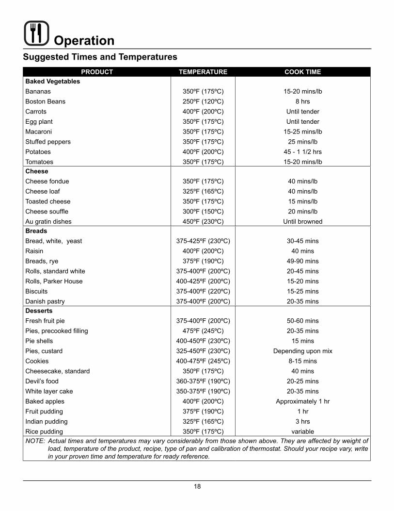
PRODUCT TEMPERATURE COOK TIMEBaked VegetablesBananasBoston BeansCarrotsEgg plantMacaroniStuffed peppersPotatoesTomatoes
350ºF (175ºC)250ºF (120ºC)400ºF (200ºC)350ºF (175ºC)350ºF (175ºC)350ºF (175ºC)400ºF (200ºC)350ºF (175ºC)
15-20 mins/lb8 hrs
Until tenderUntil tender
15-25 mins/lb25 mins/lb
45 - 1 1/2 hrs15-20 mins/lb
CheeseCheese fondueCheese loafToasted cheeseCheese souffleAu gratin dishes
350ºF (175ºC)325ºF (165ºC)350ºF (175ºC)300ºF (150ºC)450ºF (230ºC)
40 mins/lb40 mins/lb15 mins/lb20 mins/lb
Until brownedBreadsBread, white, yeastRaisinBreads, ryeRolls, standard whiteRolls, Parker HouseBiscuitsDanish pastry
375-425ºF (230ºC)400ºF (200ºC)375ºF (190ºC)
375-400ºF (200ºC)400-425ºF (200ºC)375-400ºF (220ºC)375-400ºF (200ºC)
30-45 mins40 mins
49-90 mins20-45 mins15-20 mins15-25 mins20-35 mins
DessertsFresh fruit piePies, precooked fillingPie shellsPies, custardCookiesCheesecake, standardDevil’s foodWhite layer cakeBaked applesFruit puddingIndian puddingRice pudding
375-400ºF (200ºC)475ºF (245ºC)
400-450ºF (230ºC)325-450ºF (230ºC)400-475ºF (245ºC)
350ºF (175ºC)360-375ºF (190ºC)350-375ºF (190ºC)
400ºF (200ºC)375ºF (190ºC)325ºF (165ºC)350ºF (175ºC)
50-60 mins20-35 mins
15 minsDepending upon mix
8-15 mins40 mins
20-25 mins20-35 mins
Approximately 1 hr1 hr3 hrs
variableNOTE: Actual times and temperatures may vary considerably from those shown above. They are affected by weight of
load, temperature of the product, recipe, type of pan and calibration of thermostat. Should your recipe vary, write in your proven time and temperature for ready reference.
19
MaintenanceCleaning and Preventative Maintenance
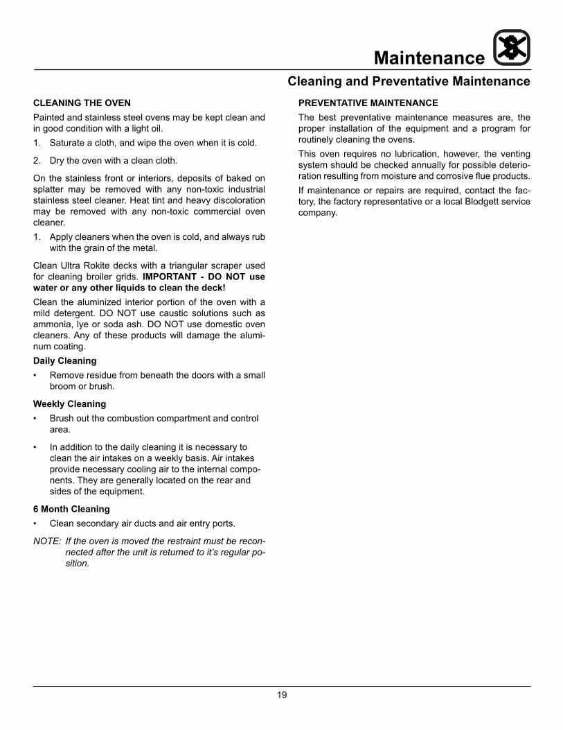
CLEANING THE OVENPainted and stainless steel ovens may be kept clean and in good condition with a light oil.1. Saturate a cloth, and wipe the oven when it is cold.
2. Dry the oven with a clean cloth.
On the stainless front or interiors, deposits of baked on splatter may be removed with any non-toxic industrial stainless steel cleaner. Heat tint and heavy discoloration may be removed with any non-toxic commercial oven cleaner.1. Apply cleaners when the oven is cold, and always rub
with the grain of the metal.
Clean Ultra Rokite decks with a triangular scraper used for cleaning broiler grids. IMPORTANT - DO NOT use water or any other liquids to clean the deck!Clean the aluminized interior portion of the oven with a mild detergent. DO NOT use caustic solutions such as ammonia, lye or soda ash. DO NOT use domestic oven cleaners. Any of these products will damage the alumi-num coating.Daily Cleaning• Remove residue from beneath the doors with a small
broom or brush.
Weekly Cleaning• Brush out the combustion compartment and control
area.
• In addition to the daily cleaning it is necessary to clean the air intakes on a weekly basis. Air intakes provide necessary cooling air to the internal compo-nents. They are generally located on the rear and sides of the equipment.
6 Month Cleaning• Clean secondary air ducts and air entry ports.
NOTE: If the oven is moved the restraint must be recon-nected after the unit is returned to it’s regular po-sition.
PREVENTATIVE MAINTENANCEThe best preventative maintenance measures are, the proper installation of the equipment and a program for routinely cleaning the ovens.This oven requires no lubrication, however, the venting system should be checked annually for possible deterio-ration resulting from moisture and corrosive flue products.If maintenance or repairs are required, contact the fac-tory, the factory representative or a local Blodgett service company.
20
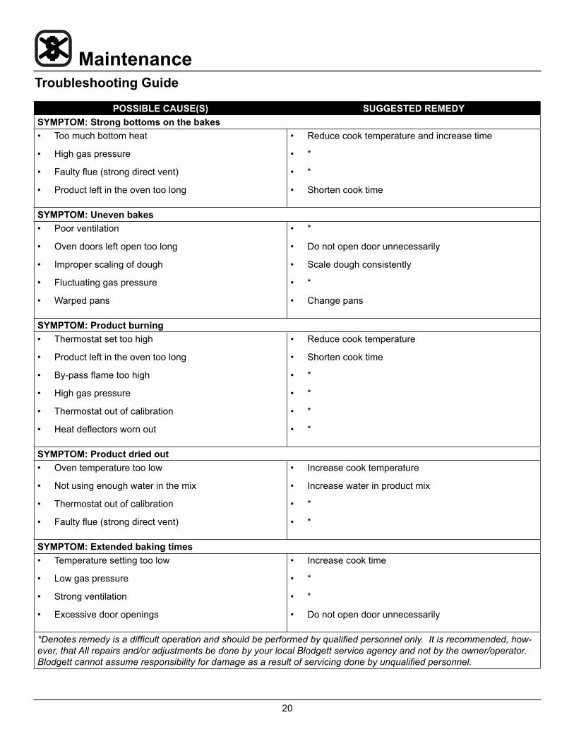
MaintenanceTroubleshooting Guide
POSSIBLE CAUSE(S) SUGGESTED REMEDYSYMPTOM: Strong bottoms on the bakes• Too much bottom heat
• High gas pressure
• Faulty flue (strong direct vent)
• Product left in the oven too long
• Reduce cook temperature and increase time
• *
• *
• Shorten cook time
SYMPTOM: Uneven bakes• Poor ventilation
• Oven doors left open too long
• Improper scaling of dough
• Fluctuating gas pressure
• Warped pans
• *
• Do not open door unnecessarily
• Scale dough consistently
• *
• Change pans
SYMPTOM: Product burning• Thermostat set too high
• Product left in the oven too long
• By-pass flame too high
• High gas pressure
• Thermostat out of calibration
• Heat deflectors worn out
• Reduce cook temperature
• Shorten cook time
• *
• *
• *
• *
SYMPTOM: Product dried out• Oven temperature too low
• Not using enough water in the mix
• Thermostat out of calibration
• Faulty flue (strong direct vent)
• Increase cook temperature
• Increase water in product mix
• *
• *
SYMPTOM: Extended baking times• Temperature setting too low
• Low gas pressure
• Strong ventilation
• Excessive door openings
• Increase cook time
• *
• *
• Do not open door unnecessarily
*Denotes remedy is a difficult operation and should be performed by qualified personnel only. It is recommended, how-ever, that All repairs and/or adjustments be done by your local Blodgett service agency and not by the owner/operator. Blodgett cannot assume responsibility for damage as a result of servicing done by unqualified personnel.