9 March 2004 GIFTS Blackbody Subsystem Critical Design Review Blackbody Mechanical Design Doug Adler...
49
<GIFTS_BB_CDR_Mech_Thermal.ppt> 9 March 2004 GIFTS Blackbody Subsystem Critical Design Review Blackbody Mechanical Design Doug Adler 9 March 2004
-
Upload
jade-edwards -
Category
Documents
-
view
231 -
download
0
Transcript of 9 March 2004 GIFTS Blackbody Subsystem Critical Design Review Blackbody Mechanical Design Doug Adler...
<GIFTS_BB_CDR_Mech_Thermal.ppt>9 March 2004
GIFTSBlackbody SubsystemCritical Design Review
Blackbody Mechanical Design
Doug Adler
9 March 2004
<GIFTS_BB_CDR_Mech_Thermal.ppt>9 March 2004
Slide 2
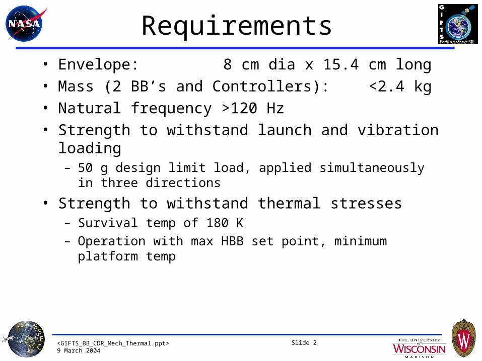
Requirements• Envelope:
8 cm dia x 15.4 cm long
• Mass (2 BB’s and Controllers):
<2.4 kg
• Natural frequency >120 Hz
• Strength to withstand launch and vibration loading– 50 g design limit load, applied simultaneously in three directions
• Strength to withstand thermal stresses– Survival temp of 180 K
– Operation with max HBB set point, minimum platform temp
<GIFTS_BB_CDR_Mech_Thermal.ppt>9 March 2004
Slide 3
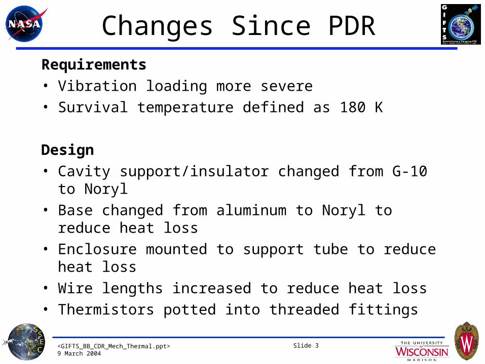
Changes Since PDRRequirements
• Vibration loading more severe
• Survival temperature defined as 180 K
Design
• Cavity support/insulator changed from G-10 to Noryl
• Base changed from aluminum to Noryl to reduce heat loss
• Enclosure mounted to support tube to reduce heat loss
• Wire lengths increased to reduce heat loss
• Thermistors potted into threaded fittings
<GIFTS_BB_CDR_Mech_Thermal.ppt>9 March 2004
Slide 4
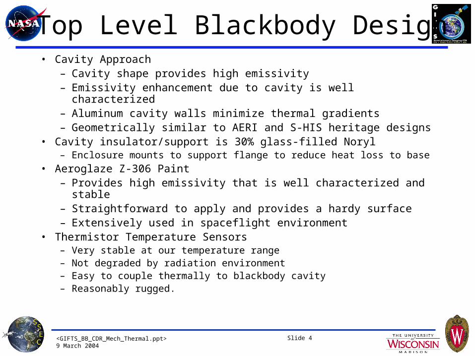
Top Level Blackbody Design• Cavity Approach
– Cavity shape provides high emissivity– Emissivity enhancement due to cavity is well characterized– Aluminum cavity walls minimize thermal gradients– Geometrically similar to AERI and S-HIS heritage designs
• Cavity insulator/support is 30% glass-filled Noryl– Enclosure mounts to support flange to reduce heat loss to base
• Aeroglaze Z-306 Paint– Provides high emissivity that is well characterized and stable– Straightforward to apply and provides a hardy surface– Extensively used in spaceflight environment
• Thermistor Temperature Sensors– Very stable at our temperature range – Not degraded by radiation environment – Easy to couple thermally to blackbody cavity– Reasonably rugged.
<GIFTS_BB_CDR_Mech_Thermal.ppt>9 March 2004
Slide 5
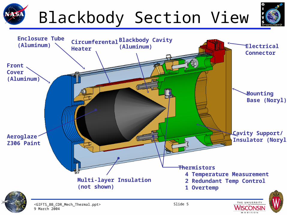
Blackbody Section ViewEnclosure Tube(Aluminum)
FrontCover(Aluminum)
Multi-layer Insulation(not shown)
Cavity Support/Insulator (Noryl)
ElectricalConnector
MountingBase (Noryl)
Circumferental Heater
Thermistors 4 Temperature Measurement 2 Redundant Temp Control 1 Overtemp
Blackbody Cavity(Aluminum)
AeroglazeZ306 Paint
<GIFTS_BB_CDR_Mech_Thermal.ppt>9 March 2004
Slide 6
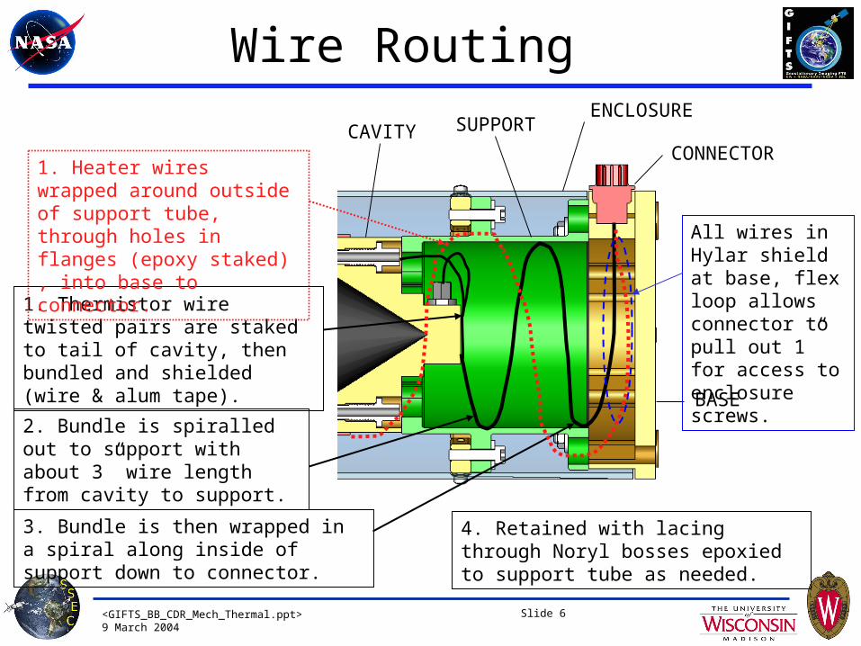
1. Thermistor wire twisted pairs are staked to tail of cavity, then bundled and shielded (wire & alum tape).
2. Bundle is spiralled out to support with about 3” wire length from cavity to support.
3. Bundle is then wrapped in a spiral along inside of support down to connector.
CAVITY SUPPORT
BASE
CONNECTOR
ENCLOSURE
Wire Routing
1. Heater wires wrapped around outside of support tube, through holes in flanges (epoxy staked) , into base to connector.
4. Retained with lacing through Noryl bosses epoxied to support tube as needed.
All wires in Hylar shield at base, flex loop allows connector to pull out 1” for access to enclosure screws.

<GIFTS_BB_CDR_Mech_Thermal.ppt>9 March 2004
Slide 7
Mechanical Interface - Envelope
• Dimensions in inches
<GIFTS_BB_CDR_Mech_Thermal.ppt>9 March 2004
Slide 8
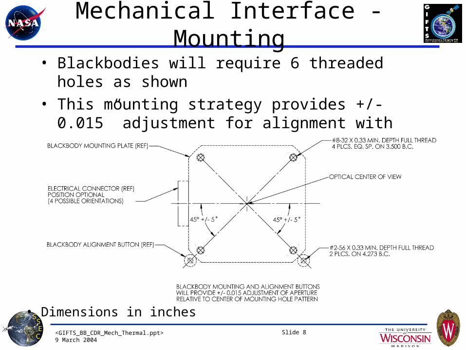
Mechanical Interface - Mounting
• Blackbodies will require 6 threaded holes as shown
• This mounting strategy provides +/- 0.015” adjustment for alignment with provisions for maintaining alignment if BB is removed/replaced
• Dimensions in inches
<GIFTS_BB_CDR_Mech_Thermal.ppt>9 March 2004
Slide 9
Blackbody Alignment Tool• UW will provide SDL a Blackbody Alignment Tool to aid in the optical
alignment of the blackbody to the SM Optics Bench.• The tool closely represents key mechanical dimensions and the overall
envelope of the flight blackbody assembly and can thus serve as both a surrogate for alignment and as a fit-check tool.
• The tool will have a translucent target at the position of the blackbody cavity entrance aperture (the perimeter of the aperture will be outlined on the target).
• Images from projections originating at the focal plane can be marked on the translucent target and the tool can be repositioned to center the images within the blackbody aperture outline.
• When the desired alignment has been obtained the alignment buttons that register the Blackbody base flange to the Optics Bench can be positioned and staked.
• The flight blackbodies and the alignment tools are interchangeable - when their base flanges are positioned by the alignment buttons, the aperture position of the tool is identical to the aperture position of the flight blackbody.
<GIFTS_BB_CDR_Mech_Thermal.ppt>9 March 2004
Slide 10
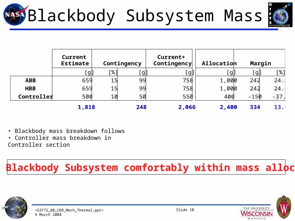
Blackbody Subsystem Mass
• Blackbody mass breakdown follows • Controller mass breakdown in Controller section
GIFTS Blackbody Subsystem comfortably within mass allocation
Current Estimate
Current+Contingency Allocation
[g] [%] [g] [g] [g] [g] [%]
ABB 659 15 99 758 1,000 242 24.2
HBB 659 15 99 758 1,000 242 24.2
Controller 500 10 50 550 400 -150 -37.5
1,818 248 2,066 2,400 334 13.9
Contingency Margin
<GIFTS_BB_CDR_Mech_Thermal.ppt>9 March 2004
Slide 11
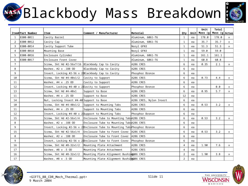
Blackbody Mass BreakdownItem#Part Number Item Comment / Manufacturer Material Qty Unit
Unit Mass (g)
Total Mass (g)Actual
1 8300-0011 Cavity Barrel Aluminum, 6061-T6 1 ea 178.0 178.0 x
2 8300-0012 Cavity Cap Aluminum, 6061-T6 1 ea 35.7 35.7 x
3 8300-0014 Cavity Support Tube Noryl GFN3 1 ea 51.3 51.3 x
4 8300-0018 Mounting Base Noryl GFN3 1 ea 59.0 59.0
5 8300-0016 Enclosure Cylinder Aluminum, 6061-T6 1 ea 161.1 161.1
6 8300-0017 Enclosure Front Cover Aluminum, 6061-T6 1 ea 60.8 60.8
7 Screw, Skt Hd #2-56x7/16 Blackbody Cap to Cavity A286 CRES 6 ea 0.35 2.1 x
8 Washer, #2 x .188 OD Blackbody Cap to Cavity A286 CRES 6 ea
9 Insert, Locking #2-56 x 2D Blackbody Cap to Cavity Phosphor Bronze 6 ea
10 Screw, Skt Hd #4-40x1/2 Cavity to Support A286 CRES 6 ea 0.73 4.4 x
11 Washer, #4 x .25 OD Cavity to Support A286 CRES 6 ea
12 Insert, Locking #4-40 x 2D Cavity to Support Phosphor Bronze 6 ea 0.0 x
13 Screw, Skt Hd #4-40x1 Support to Base A286 CRES 6 ea 0.95 5.7 x
11 Washer, #4 x .25 OD Support to Base A286 CRES 12 ea
14 Nut, Locking Insert #4-40 Support to Base A286 CRES, Nylon Insert 6 ea
10 Screw, Skt Hd #4-40x1/2 Support to Mounting Tabs A286 CRES 6 ea 0.53 3.2 x
11 Washer, #4 x .25 OD Support to Mounting Tabs A286 CRES 6 ea
12 Insert, Locking #4-40 x 2D Support to Mounting Tabs Phosphor Bronze 6 ea
15 Screw, Skt Hd #2-56x1/4 Enclosure Tube to Mounting Tabs A286 CRES 6 ea 0.53 3.2 x
8 Washer, #2 x .188 OD Enclosure Tube to Mounting Tabs A286 CRES 6 ea
9 Insert, Locking #2-56 x 2D Enclosure Tube to Mounting Tabs Phosphor Bronze 6 ea
15 Screw, Skt Hd #2-56x1/4 Enclosure Tube to Front Cover A286 CRES 6 ea 0.53 3.2 x
8 Washer, #2 x .188 OD Enclosure Tube to Front Cover A286 CRES 6 ea
9 Insert, Locking #2-56 x 2D Enclosure Tube to Front Cover Phosphor Bronze 6 ea
16 Screw, Skt Hd #8-32x1/2 Mounting Plate Attachment A286 CRES 4 ea 1.90 7.6 x
17 Washer, #8 x .5 OD Mounting Plate Attachment A286 CRES 4 ea
16 Screw, Skt Hd #8-32x1/2 Mounting Plate Alignment Bushings A286 CRES 2 ea 1.90 3.8 x
17 Washer, #8 x .5 OD Mounting Plate Alignment Bushings A286 CRES 2 ea
<GIFTS_BB_CDR_Mech_Thermal.ppt>9 March 2004
Slide 12
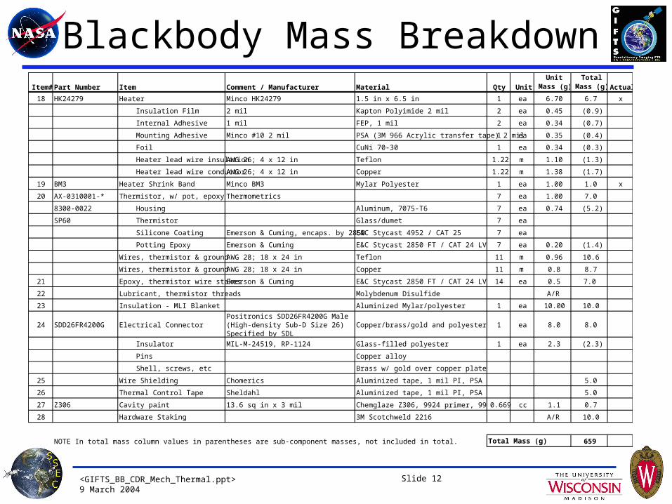
Blackbody Mass BreakdownItem#Part Number Item Comment / Manufacturer Material Qty Unit
Unit Mass (g)
Total Mass (g)Actual
18 HK24279 Heater Minco HK24279 1.5 in x 6.5 in 1 ea 6.70 6.7 x
Insulation Film 2 mil Kapton Polyimide 2 mil 2 ea 0.45 (0.9)
Internal Adhesive 1 mil FEP, 1 mil 2 ea 0.34 (0.7)
Mounting Adhesive Minco #10 2 mil PSA (3M 966 Acrylic transfer tape) 2 mil1 ea 0.35 (0.4)
Foil CuNi 70-30 1 ea 0.34 (0.3)
Heater lead wire insulation AWG 26; 4 x 12 in Teflon 1.22 m 1.10 (1.3)
Heater lead wire conductor AWG 26; 4 x 12 in Copper 1.22 m 1.38 (1.7)
19 BM3 Heater Shrink Band Minco BM3 Mylar Polyester 1 ea 1.00 1.0 x
20 AX-0310001-* Thermistor, w/ pot, epoxy Thermometrics 7 ea 1.00 7.0
8300-0022 Housing Aluminum, 7075-T6 7 ea 0.74 (5.2)
SP60 Thermistor Glass/dumet 7 ea
Silicone Coating Emerson & Cuming, encaps. by 2850E&C Stycast 4952 / CAT 25 7 ea
Potting Epoxy Emerson & Cuming E&C Stycast 2850 FT / CAT 24 LV 7 ea 0.20 (1.4)
Wires, thermistor & ground AWG 28; 18 x 24 in Teflon 11 m 0.96 10.6
Wires, thermistor & ground AWG 28; 18 x 24 in Copper 11 m 0.8 8.7
21 Epoxy, thermistor wire stakes Emerson & Cuming E&C Stycast 2850 FT / CAT 24 LV 14 ea 0.5 7.0
22 Lubricant, thermistor threads Molybdenum Disulfide A/R
23 Insulation - MLI Blanket Aluminized Mylar/polyester 1 ea 10.00 10.0
24 SDD26FR4200G Electrical ConnectorPositronics SDD26FR4200G Male (High-density Sub-D Size 26) Specified by SDL
Copper/brass/gold and polyester 1 ea 8.0 8.0
Insulator MIL-M-24519, RP-1124 Glass-filled polyester 1 ea 2.3 (2.3)
Pins Copper alloy
Shell, screws, etc Brass w/ gold over copper plate
25 Wire Shielding Chomerics Aluminized tape, 1 mil PI, PSA 5.0
26 Thermal Control Tape Sheldahl Aluminized tape, 1 mil PI, PSA 5.0
27 Z306 Cavity paint 13.6 sq in x 3 mil Chemglaze Z306, 9924 primer, 9951 thinner0.669 cc 1.1 0.7
28 Hardware Staking 3M Scotchweld 2216 A/R 10.0
NOTE In total mass column values in parentheses are sub-component masses, not included in total. 659Total Mass (g)
<GIFTS_BB_CDR_Mech_Thermal.ppt>9 March 2004
Slide 13
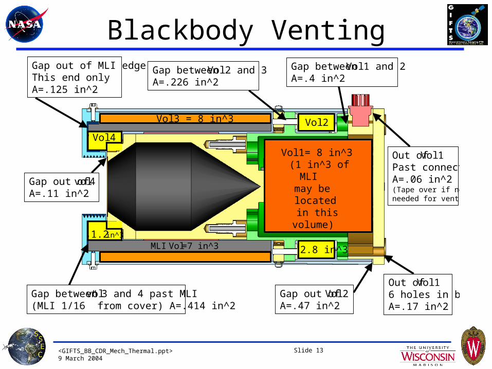
Blackbody Venting
Vol 2
MLI Vol =7 in^3
Vol 3 = 8 in^3
Vol 4
Gap between vol 3 and 4 past MLI(MLI 1/16” from cover) A=.414 in^2
Gap between Vol 2 and 3A=.226 in^2
1.2 in^3
2.8 in^3
Gap out of MLI edgeThis end onlyA=.125 in^2
Gap between Vol 1 and 2A=.4 in^2
Gap out of Vol 2A=.47 in^2
Gap out of vol 4A=.11 in^2
Out of Vol 16 holes in baseA=.17 in^2
Out of Vol 1Past connectorA=.06 in^2(Tape over if not needed for venting)
Vol 1= 8 in^3(1 in^3 of
MLImay belocatedin this
volume)
<GIFTS_BB_CDR_Mech_Thermal.ppt>9 March 2004
Slide 14
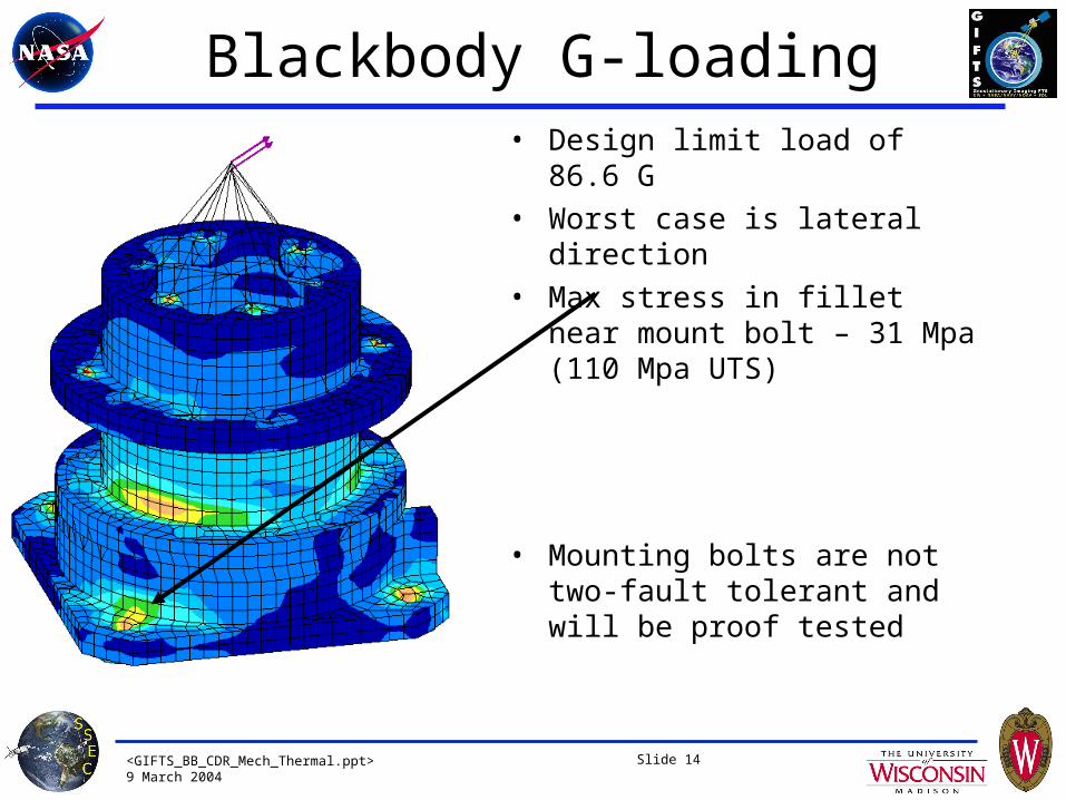
Blackbody G-loading• Design limit load of 86.6 G
• Worst case is lateral direction
• Max stress in fillet near mount bolt – 31 Mpa (110 Mpa UTS)
• Mounting bolts are not two-fault tolerant and will be proof tested
<GIFTS_BB_CDR_Mech_Thermal.ppt>9 March 2004
Slide 15
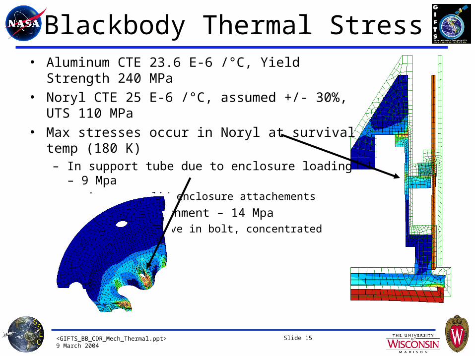
Blackbody Thermal Stress• Aluminum CTE 23.6 E-6 /°C, Yield Strength 240 MPa
• Noryl CTE 25 E-6 /°C, assumed +/- 30%, UTS 110 MPa
• Max stresses occur in Noryl at survival temp (180 K)– In support tube due to enclosure loading – 9 Mpa
• Assumes solid enclosure attachements
– At cavity attachment – 14 Mpa• Assumes no give in bolt, concentrated deflection

<GIFTS_BB_CDR_Mech_Thermal.ppt>9 March 2004
Slide 16
Blackbody Natural Frequency
• Modeled with lumped masses at enclosure and cavity cg’s
• Lumped mass trusses are point applied, so results are conservative (lower frequency)
• First mode is cantilever beam
• With fixed bolt holes, first mode at 190 Hz
• With pivot restraint, first mode at 145 Hz
<GIFTS_BB_CDR_Mech_Thermal.ppt>9 March 2004
Slide 17
PWB Analysis
• PWB board is 10 x 6 in, weight 1.213 lbf (assumed evenly distributed)
• Wedgelocks on short sides, bus connector one long side, 2-26 pin sub-D connectors on other long side
• Assumed short sides fixed or simply supported, long sides simply supported
• Eeq=3E6 psi (generic epoxy-glass with copper layers)
• Natural frequency– Assuming short sides fixed, long sides SS, natural frequency is 140 Hz
• Stress and displacement calculated using 86.6 G design limit load, same boundary conditions as above
– Maximum stress in board is 4,000 psi (factor of ten below copper and epoxy-glass yield strengths)
– Maximum displacement of board y=.066 in• General guideline is 0.01 inch per inch of board length (per SDL)
• On short side this gives a max recommended deflection of 0.060 inches
• Given conservative assumptions, we expect a more detailed analysis will show deflections are within guidelines
<GIFTS_BB_CDR_Mech_Thermal.ppt>9 March 2004
Slide 18
Verification Testing• EM level BB assembly
– Sine sweep for natural frequency identification
– Design limit load of 86.6 G (50 G in 3 directions)• Quasi-static shaker or static applied at cg
– Random vibration to acceptance level + 3 dB (8 Grms + 3 dB)
– Repeat sine sweep to verify no natural frequency shift
– Thermal cycles 160 K – 343 K
• Flight level BB assembly acceptance testing– Sine sweep for natural frequency identification
– Random vibration to acceptance level (8 Grms)
– Repeat sine sweep to verify no natural frequency shift
– Thermal cycles 170 K – 333 K (done as part of thermal balance and cycling test)
<GIFTS_BB_CDR_Mech_Thermal.ppt>9 March 2004
GIFTSBlackbody SubsystemCritical Design Review
Blackbody Thermal Design
Doug Adler
9 March 2004
<GIFTS_BB_CDR_Mech_Thermal.ppt>9 March 2004
Slide 20
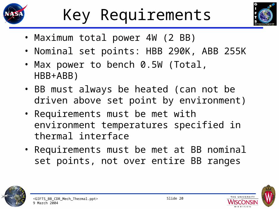
Key Requirements• Maximum total power 4W (2 BB)
• Nominal set points: HBB 290K, ABB 255K
• Max power to bench 0.5W (Total, HBB+ABB)
• BB must always be heated (can not be driven above set point by environment)
• Requirements must be met with environment temperatures specified in thermal interface
• Requirements must be met at BB nominal set points, not over entire BB ranges

<GIFTS_BB_CDR_Mech_Thermal.ppt>9 March 2004
Slide 21
Changes Since PDR
Requirements• Thermal interface is significantly more complex (was isothermal 265 K)
– Mounted to platform/optics bench at 200 K, rising to 220 K end of mission– Baffle above blackbodies varies from 140-300 K– Mirror mount above blackbodies held at 250 K– Instrument survival temperature of 180 K– Heat loss through platform limited to 0.5 W total (ABB+HBB)
• Both blackbodies now heated, controlled to ‘ambient’ and hot temperatures of 255 K and 290 K respectively
Design• Cavity support/insulator changed from G-10 to Noryl• Enclosure mounted to support tube to reduce heat loss• Internal wire length added to reduce heat loss• Base modified to accommodate thermistor and flanges thickened for strength
<GIFTS_BB_CDR_Mech_Thermal.ppt>9 March 2004
Slide 22
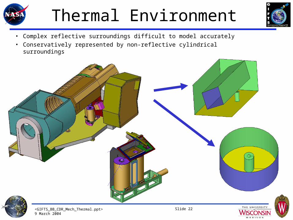
Thermal Environment• Complex reflective surroundings difficult to model accurately
• Conservatively represented by non-reflective cylindrical surroundings
<GIFTS_BB_CDR_Mech_Thermal.ppt>9 March 2004
Slide 23
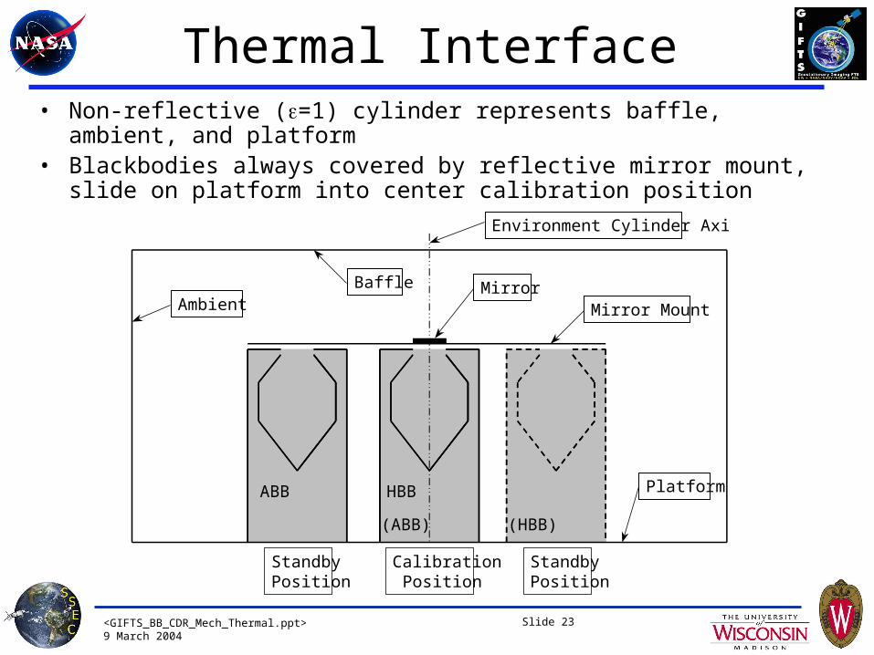
Thermal Interface• Non-reflective (=1) cylinder represents baffle, ambient, and platform• Blackbodies always covered by reflective mirror mount, slide on platform into
center calibration position
HBBABB
Mirror Mount
BaffleAmbient
Platform
(ABB) (HBB)
Mirror
StandbyPosition
CalibrationPosition
StandbyPosition
Environment Cylinder Axis
<GIFTS_BB_CDR_Mech_Thermal.ppt>9 March 2004
Slide 24
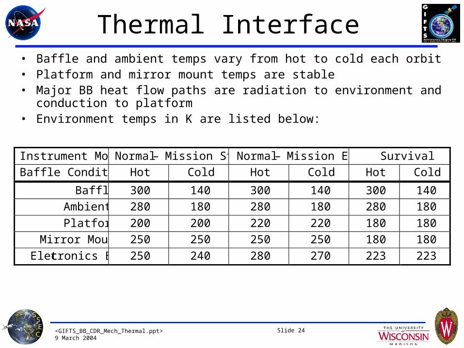
Thermal Interface• Baffle and ambient temps vary from hot to cold each orbit• Platform and mirror mount temps are stable• Major BB heat flow paths are radiation to environment and conduction to
platform• Environment temps in K are listed below:
Instrument Mode Normal – Mission Start Normal – Mission End Survival
Baffle Condition Hot Cold Hot Cold Hot Cold
Baffle 300 140 300 140 300 140
Ambient 280 180 280 180 280 180
Platform 200 200 220 220 180 180
Mirror Mount 250 250 250 250 180 180
Electronics Box 250 240 280 270 223 223

<GIFTS_BB_CDR_Mech_Thermal.ppt>9 March 2004
Slide 25
Thermal Model Assumptions• MLI emissivity = 0.01-0.04, 0.04 used for worst case
• BB surfaces covered with low- tape (= 0.03-0.05) wherever possible, 0.05 used for worst case
• Wires well coupled to connector (worst case for power loss)
• During calibration flip-in mirror provides cavity aperture view to 60K
• Sliding platform is thermally coupled to optics bench, and can absorb .5W without significant temperature increase
• No heat flow in/out through external wiring harness to electronics box
<GIFTS_BB_CDR_Mech_Thermal.ppt>9 March 2004
Slide 26
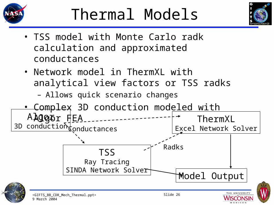
Thermal Models• TSS model with Monte Carlo radk calculation and
approximated conductances
• Network model in ThermXL with analytical view factors or TSS radks– Allows quick scenario changes
• Complex 3D conduction modeled with Algor FEA
TSSRay Tracing
SINDA Network Solver
ThermXLExcel Network Solver
Algor3D conduction Conductances
Radks
Model Output
<GIFTS_BB_CDR_Mech_Thermal.ppt>9 March 2004
Slide 27
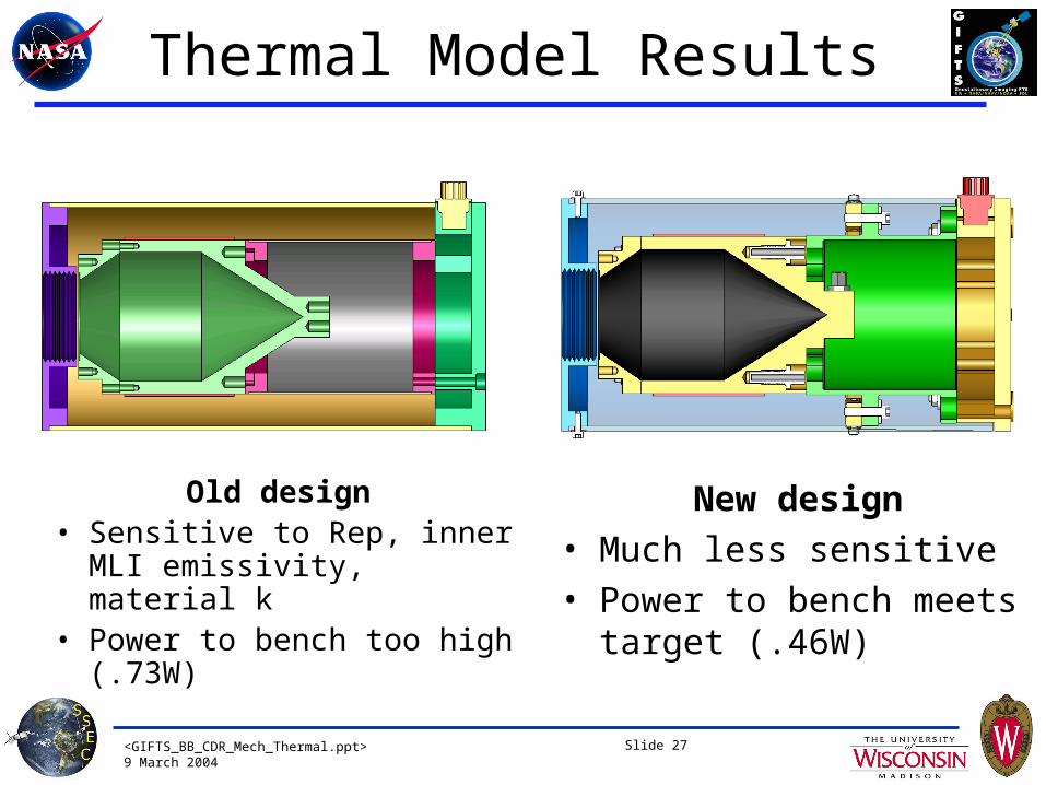
Thermal Model Results
Old design • Sensitive to Rep, inner MLI
emissivity, material k• Power to bench too high
(.73W)
New design
• Much less sensitive
• Power to bench meets target (.46W)
<GIFTS_BB_CDR_Mech_Thermal.ppt>9 March 2004
Slide 28
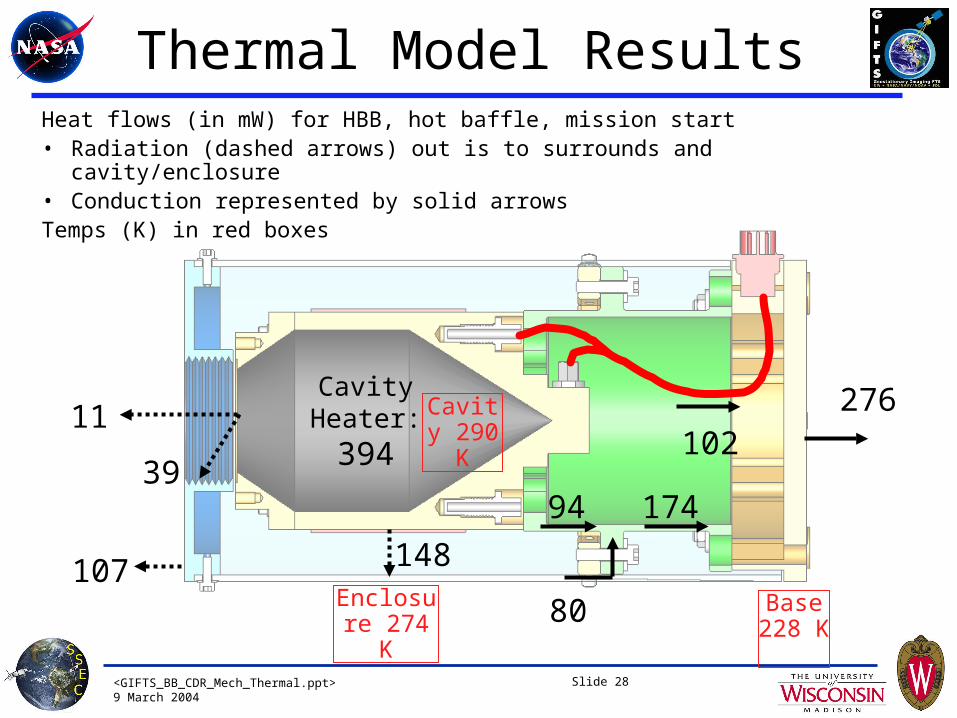
Thermal Model ResultsHeat flows (in mW) for HBB, hot baffle, mission start• Radiation (dashed arrows) out is to surrounds and cavity/enclosure• Conduction represented by solid arrowsTemps (K) in red boxes
276
148
17494
11
107
102
CavityHeater:
394
80Enclosure 274 K
Cavity 290 K
Base 228 K
39
<GIFTS_BB_CDR_Mech_Thermal.ppt>9 March 2004
Slide 29
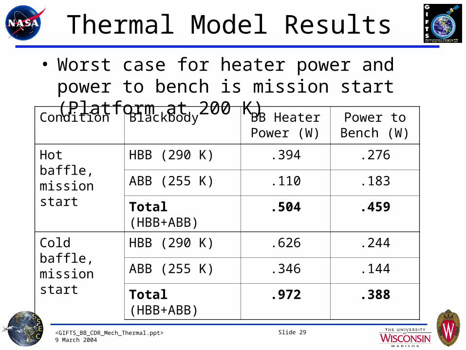
Thermal Model Results
• Worst case for heater power and power to bench is mission start (Platform at 200 K)
Condition Blackbody BB Heater Power (W)
Power to Bench (W)
Hot baffle, mission start
HBB (290 K) .394 .276
ABB (255 K) .110 .183
Total (HBB+ABB) .504 .459
Cold baffle, mission start
HBB (290 K) .626 .244
ABB (255 K) .346 .144
Total (HBB+ABB) .972 .388
<GIFTS_BB_CDR_Mech_Thermal.ppt>9 March 2004
Slide 30
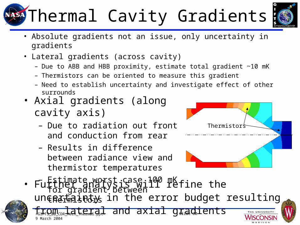
Thermal Cavity Gradients• Absolute gradients not an issue, only uncertainty in gradients
• Lateral gradients (across cavity)– Due to ABB and HBB proximity, estimate total gradient ~10 mK
– Thermistors can be oriented to measure this gradient
– Need to establish uncertainty and investigate effect of other surrounds• Axial gradients (along cavity axis)
– Due to radiation out front and conduction from rear
– Results in difference between radiance view and thermistor temperatures
– Estimate worst case 100 mK for gradient between thermistors
• Further analysis will refine the uncertainty in the error budget resulting from lateral and axial gradients
Thermistors
<GIFTS_BB_CDR_Mech_Thermal.ppt>9 March 2004
Slide 31
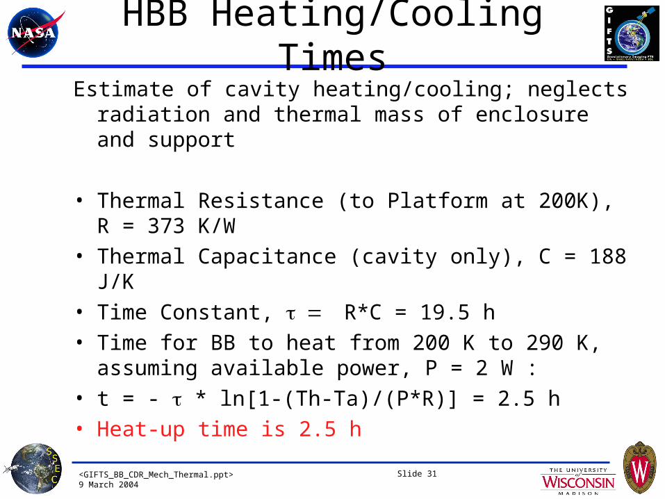
HBB Heating/Cooling TimesEstimate of cavity heating/cooling; neglects radiation and
thermal mass of enclosure and support
• Thermal Resistance (to Platform at 200K), R = 373 K/W
• Thermal Capacitance (cavity only), C = 188 J/K
• Time Constant, R*C = 19.5 h
• Time for BB to heat from 200 K to 290 K, assuming available power, P = 2 W :
• t = - * ln[1-(Th-Ta)/(P*R)] = 2.5 h
• Heat-up time is 2.5 h
<GIFTS_BB_CDR_Mech_Thermal.ppt>9 March 2004
Slide 32
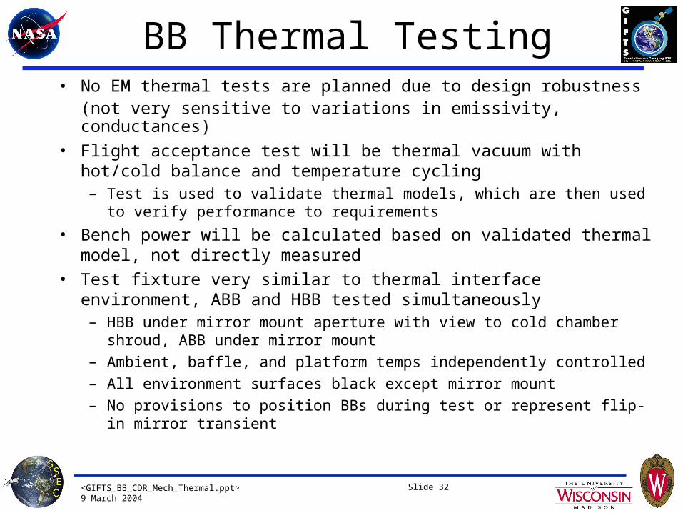
BB Thermal Testing• No EM thermal tests are planned due to design robustness
(not very sensitive to variations in emissivity, conductances)
• Flight acceptance test will be thermal vacuum with hot/cold balance and temperature cycling– Test is used to validate thermal models, which are then used to verify
performance to requirements
• Bench power will be calculated based on validated thermal model, not directly measured
• Test fixture very similar to thermal interface environment, ABB and HBB tested simultaneously– HBB under mirror mount aperture with view to cold chamber shroud, ABB
under mirror mount
– Ambient, baffle, and platform temps independently controlled
– All environment surfaces black except mirror mount
– No provisions to position BBs during test or represent flip-in mirror transient
<GIFTS_BB_CDR_Mech_Thermal.ppt>9 March 2004
Slide 33
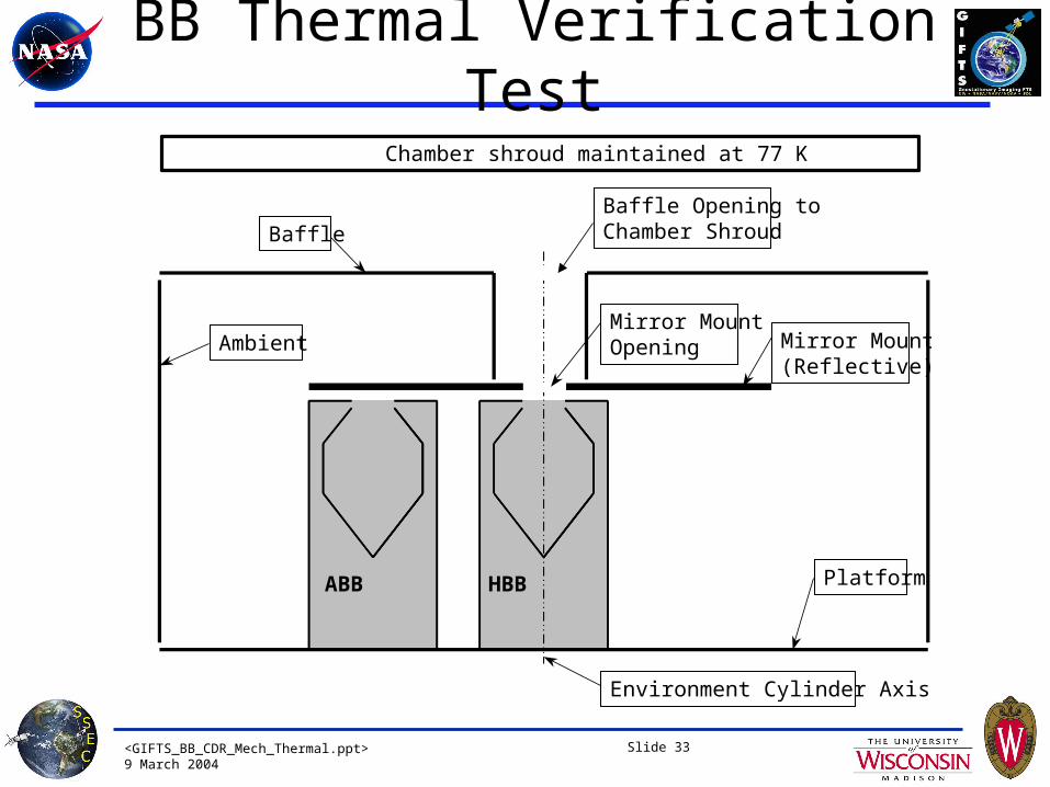
BB Thermal Verification Test
HBBABB
Mirror Mount(Reflective)
Baffle
Ambient
Platform
Mirror MountOpening
Environment Cylinder Axis
Baffle Opening to Chamber Shroud
Chamber shroud maintained at 77 K

<GIFTS_BB_CDR_Mech_Thermal.ppt>9 March 2004
Slide 34
BB Thermal Verification Test • Test Measurements:
– BB thermistors and heater power
– Thermocouples applied to BB enclosures and connectors
– Monitor surroundings, fixture temperatures
• Test Procedure– Hot thermal balance
• Hot baffle, end of life platform temp (220 K)
• Worst case for ABB overheat
– Cold thermal balance• Cold baffle, mission start platform temp (200 K)
• Gives worst case heater powers
– Temperature cycles – 12 cycles 170-333 K
– Repeat hot & cold balance

<GIFTS_BB_CDR_Mech_Thermal.ppt>9 March 2004
Slide 35
Next Steps
• More detailed cavity modeling will be done to further refine the uncertainty budget– Flip-in transient
– Cross-cavity gradient
– Axial gradient
<GIFTS_BB_CDR_Mech_Thermal.ppt>9 March 2004
GIFTSBlackbody SubsystemCritical Design Review
Thermistors
Doug Adler
9 March 2004
<GIFTS_BB_CDR_Mech_Thermal.ppt>9 March 2004
Slide 37
Thermistor Selection• Selected Thermometrics SP60 thermistors
– SDL SABER mission heritage
– Smaller size than YSI
– Thermometrics measurement accuracy for stability testing
• Drift rated at 0.02% (of nominal 25°C resistance) per year, equates to 5 mK/year– Rated at 105°C, less drift at lower temperatures
– SABER results showed up to 20 mK drift with initial 5 cycles to 77 K, < 1 mK drift with additional 5 cycles
<GIFTS_BB_CDR_Mech_Thermal.ppt>9 March 2004
Slide 38
Thermistor Assembly Design• Packaged into threaded aluminum housing
– Similar mounting to SABER (potting, diameter, etc)
– Allows stability testing in as-mounted condition • Aluminum housing ensures no additional stresses due to thermal cycling after
installation in cavity
– Lead wire joint encased in housing, eliminates risk of solder heat or handling damage affecting stability
– Conductive epoxy used for thread lubrication, retention, and enhanced conduction to cavity
– Dual thread-epoxy thermal path provides robustness and stability
– 7075 chosen for reduced thread galling into 6061 cavity, and increased strength in the event of thermistor removal
<GIFTS_BB_CDR_Mech_Thermal.ppt>9 March 2004
Slide 39
Flange Contact
Thread Contact
Epoxy LengthsL/4
L/2
L
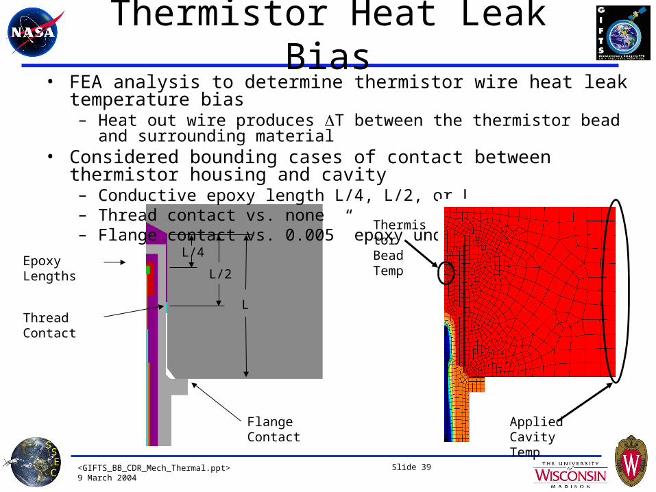
• FEA analysis to determine thermistor wire heat leak temperature bias – Heat out wire produces T between the thermistor bead and surrounding material
• Considered bounding cases of contact between thermistor housing and cavity – Conductive epoxy length L/4, L/2, or L– Thread contact vs. none– Flange contact vs. 0.005” epoxy under flange
Thermistor Heat Leak Bias
Thermistor BeadTemp
Applied Cavity Temp

<GIFTS_BB_CDR_Mech_Thermal.ppt>9 March 2004
Slide 40
Case Thread Contact
Flange Contact
Epoxy Length
Temperature Error (mK)
1 No Yes L/4 14
2 No Yes L/2 8
3 No Yes L 4
4 No Epoxy L 5
5 Yes Yes None 4
6 Yes Yes L 4
• FEA results based on worst case heat flux out wires of 25 mW per thermistor– Assumes cavity at 313 K, baffle/ambient at 140 K, platform at 190 K– Assumes leads not staked to cavity (or ineffective stake), as long term stake performance is
difficult to verify– Assumes wires wrapped in low- tape
• The cavity bores will be filled with conductive epoxy prior to thermistor housing installation, excess will exit through venting slot
• This will ensure performance of Case 2 at a minimum
Thermistor Heat Leak Bias
Assumed for budget
Design intent
<GIFTS_BB_CDR_Mech_Thermal.ppt>9 March 2004
Slide 41
Thermistor Heat Leak Bias• FEA results were checked with a test on EM cavity and prototype
thermistors– Thermistor housings installed with conductive paste– Cavity insulated, controlled to temp just above ambient– Leads from one thermistor dipped into ice bath – If thermistor had no gradient effect, predict 5-10 mK delta from ice dip
lead to opposite side of cavity– Measured 10-15 mK delta to opposite side, which indicates 5 +/- 5 mK
thermistor temperature gradient effect

<GIFTS_BB_CDR_Mech_Thermal.ppt>9 March 2004
Slide 42
Thermistor Test PlanAll flight and backup parts undergo this verification testing• Normal “ultrastable” thermistor stability screening performed by
Thermometrics• Lead wires attached and probes installed into housings• Test procedure (based on SDL SABER testing)
– Ro check – Vibration to 50g quasi-static, 8g +3dB random– Ro check– Thermal cycles – 5 cycles 170-333 K (-103 to +60 C)– Ro check– Thermal cycles – 5 cycles 170-333 K (-103 to +60 C)– Ro check and three point calibration (-40, 0, 40 C)
• Expect some thermistor drift during first set of thermal cycles based on SDL SABER results
• Second set of thermal cycles verifies no additional drifting
Backup parts will be maintained for long term drift testing

<GIFTS_BB_CDR_Mech_Thermal.ppt>9 March 2004
Slide 43
Backup Slides
<GIFTS_BB_CDR_Mech_Thermal.ppt>9 March 2004
Slide 44
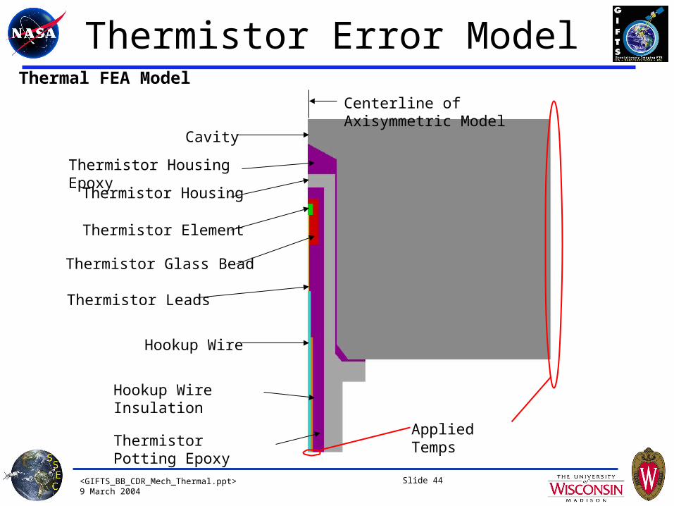
Hookup Wire Insulation
Thermistor Housing Epoxy
Hookup Wire
Thermistor Potting Epoxy
Thermistor Element
Thermistor Glass Bead
Thermistor Leads
Cavity
Thermistor Housing
Applied Temps
Centerline of Axisymmetric Model
Thermal FEA Model
Thermistor Error Model
<GIFTS_BB_CDR_Mech_Thermal.ppt>9 March 2004
Slide 45
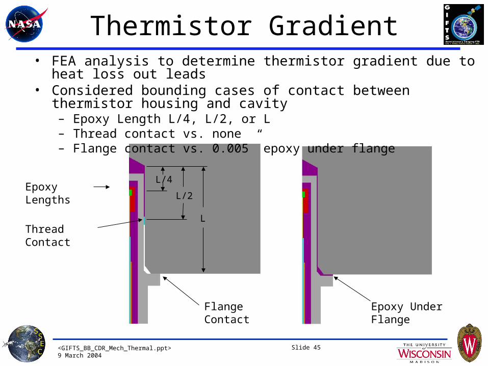
Flange Contact
Thread Contact
Epoxy LengthsL/4
L/2
L
Epoxy Under Flange
• FEA analysis to determine thermistor gradient due to heat loss out leads• Considered bounding cases of contact between thermistor housing and cavity
– Epoxy Length L/4, L/2, or L– Thread contact vs. none– Flange contact vs. 0.005” epoxy under flange
Thermistor Gradient
<GIFTS_BB_CDR_Mech_Thermal.ppt>9 March 2004
Slide 46
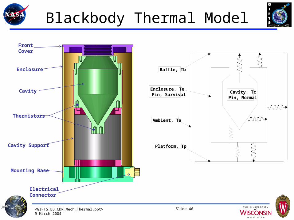
Blackbody Thermal Model
Enclosure
FrontCover
Cavity Support
ElectricalConnector
Mounting Base
Thermistors
Cavity Cavity, TcPin, Normal
Enclosure, TePin, Survival
Ambient, Ta
Baffle, Tb
Platform, Tp

<GIFTS_BB_CDR_Mech_Thermal.ppt>9 March 2004
Slide 47
• Neglected radiation, conduction only to edges (wedgelocks) at 50°C
• Modeled board as single layer with equivalent lateral conductivity based on copper and polyimide layer thicknesses
• Heat flux into board assumed uniform over each component’s area
• Components shown total .81W, remaining .39W evenly distributed over remaining board surface
• Results in max temp of 54°C at 1.2W power dissipation
• Heat to left edge is .43W, heat to right edge .77W
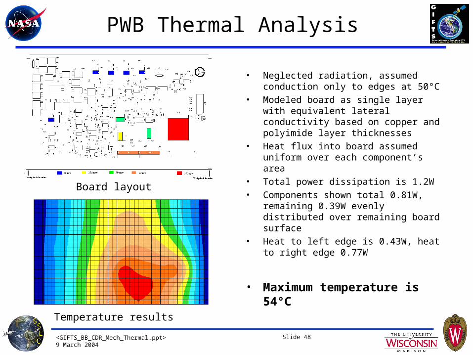
Board layout
Temperature results
PWB Thermal Analysis
WedgelockWedgelock
<GIFTS_BB_CDR_Mech_Thermal.ppt>9 March 2004
Slide 48
PWB Thermal Analysis
• Neglected radiation, assumed conduction only to edges at 50°C
• Modeled board as single layer with equivalent lateral conductivity based on copper and polyimide layer thicknesses
• Heat flux into board assumed uniform over each component’s area
• Total power dissipation is 1.2W• Components shown total 0.81W, remaining
0.39W evenly distributed over remaining board surface
• Heat to left edge is 0.43W, heat to right edge 0.77W
• Maximum temperature is 54°C
Board layout
Temperature results
<GIFTS_BB_CDR_Mech_Thermal.ppt>9 March 2004
Slide 49
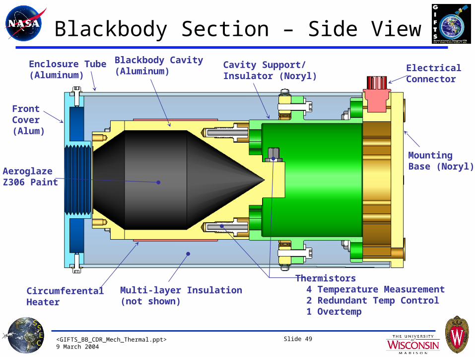
Blackbody Section – Side View
Enclosure Tube(Aluminum)
FrontCover(Alum)
Multi-layer Insulation(not shown)
Cavity Support/Insulator (Noryl)
ElectricalConnector
MountingBase (Noryl)
Circumferental Heater
Thermistors 4 Temperature Measurement 2 Redundant Temp Control 1 Overtemp
Blackbody Cavity(Aluminum)
AeroglazeZ306 Paint