
9 drilling rotarytable - rgn.hrrgn.hr/.../_private/Krakow_drilling/9_drilling_rotarytable.pdf ·...
77
Davorin Matanović Drilling_rotary table
Transcript of 9 drilling rotarytable - rgn.hrrgn.hr/.../_private/Krakow_drilling/9_drilling_rotarytable.pdf ·...

Davorin Matanović
Drilling_rotary table

Rotary table
• The function of the rotary table is to rotate and to hold the drill string.
• When drilling is going on, the rotary turns to the right, or clockwise.
• Rotation in opposite direction is possible too.
• When the pipe is pulled from the wellbore, the rotary supports the string on slips during intervals when the pipe is not being suspended from the hook.
ROTARY
TABLE
MASTER
BUSHING
KELLY
BUSHING
KELLY
SUB
KELLY

• Modern design of the rotary table protects the inner elements of the rotary.
• The top of the rotary has a flat, clean work surface with skid-proof footing for the crewmen.
• The foundation is either a cast steel base or a reinforced fabricated steel base.
• Holes are provided for attaching lifting hooks when the rotary must be handled.
• Oil reservoirs for oil-bath lubricant are cast as an integral part of the base.

Rotary inner construction
1. BASE 15. PINION SHAFT 29. UPER RACE 2. TABLE GUARD 16. CAPSULE SHIM 30. BALLS 3. RING GEAR 17. STUD 31. LOWER RACE 4. HOLD-DOWN RING 18. COVER PLATE 32. PINION 5. TABLE 19. CAP SCREW 33. DRAIN PLUG 6. TABLE BUSHING 20. SPROCKET KEY 34. PINION END COVER PLATE 7. ADAPTER BUSHING 21. SAFETY CLAMP NUT 35. PINION END ROLLER BEARING 8. TABLE BUSHING 22. HOLD-DOWN SHIMS 36. SPROCKET END ROLLER BEARING 9. BEARING – UPPER RACE 23. ELASTIC STOP NUT 37. GASKET 10. PINION KEY 24. TABLE BEARING SHIMS 38. OIL SEAL 11. MUD SEAL RING 25. BEARING – LOWER RACE 39. SPROCKET 12. MUD SEAL SPRING 26. BALL SPACER 40. CAP SCREW 13. CAP SCREW 27. LOWER MUD SEAL RING 14. CAPSULE 28. MUD SEAL SPRING

API ROTARY
TABLE OPENING
SIZE A B C Dmm mm mm mm mm (") (") (") (") (")445 445 467 133 44,5
(17 1/2) (17 1/2) (18 3/16) (5 1/4) (1 3/4))521 521 538 133 44,5
(20 1/2) (20 1/2) (21 3/16) (5 1/4) (1 3/4)699 699 716 133 44,5
(27 1/2) (27 1/2) (28 3/16) (5 1/4) (1 3/4))953 953
(37 1/2) (37 1/2)1257 1257
(49 1/2) (49 1/2)
•The diameter of the opening through the table for the passage of bits and other tools (A) indicates the general capacity of the rotary. Another size designation is the load capacity which ranges from 1000 kN do 6000 kN (100 to 600 tons).
•E – Tables are available in two sizes, 1117,6 mm (44") and 1352,55 mm (53 1/4")

• Rotation is accomplished through the use of two pinions.
HOUSING
TABLE LOCK
MUD SEAL
DECK GEAR AND
PINION OIL SEALSPINION
BEARINGS
SHAFT
MAIN BEARING
HOLD-DOWN BEARING
LOCK PIN
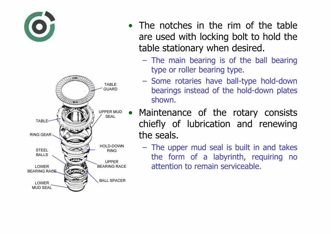
• The notches in the rim of the table are used with locking bolt to hold the table stationary when desired.
– The main bearing is of the ball bearing type or roller bearing type.
– Some rotaries have ball-type hold-down bearings instead of the hold-down plates shown.
• Maintenance of the rotary consists chiefly of lubrication and renewing the seals.
– The upper mud seal is built in and takes the form of a labyrinth, requiring no attention to remain serviceable.
TABLE
GUARD
UPPER MUD
SEAL
HOLD-DOWN
RING
UPPER
BEARING RACE
BALL SPACER
TABLE
RING GEAR
LOWER
MUD SEAL
LOWER
BEARING RACE
STEEL
BALLS

• Accessories used with the rotary to carry out its functions of rotating the tools in the hole and supporting the drill string while making connections or trips are:– the kelly drive
bushing,
– the master bushing, and
– the slips.
KELLY DRIVE BUSHING
MASTER BUSHING
ROTARY TABLE

• Engagement of the kelly drive bushing and master bushing can be accomplished in two ways:
a) by drive pins fixed into the bottom of the kelly
bushing and fitting into holes bored in the top of master bushing surface,
b) by a square on the bottom of the kelly drive bushing fitting into the corresponding square recess
of the master bushing

MASTER BUSHING
• The master bushing is the device that fits into the rotary table and serves as a means for engaging the kelly bushing with the rotary table.
• It also provides the tapered surface to support the slips when holding the pipe.
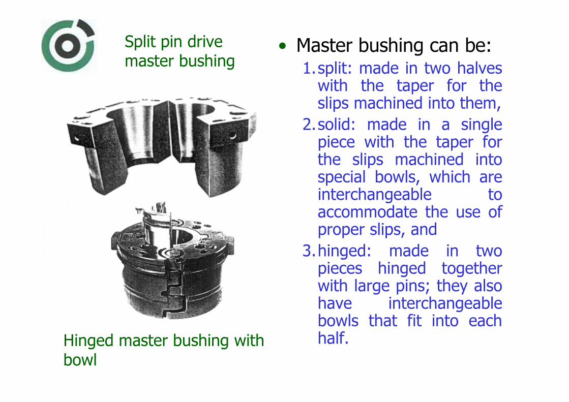
• Master bushing can be:1.split: made in two halves
with the taper for the slips machined into them,
2.solid: made in a single piece with the taper for the slips machined into special bowls, which are interchangeable to accommodate the use of proper slips, and
3.hinged: made in two pieces hinged together with large pins; they also have interchangeable bowls that fit into each half.
Split pin drive master bushing
Hinged master bushing with bowl
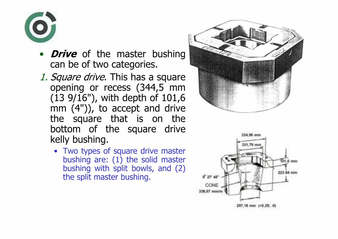
• Drive of the master bushing can be of two categories.
1. Square drive. This has a square opening or recess (344,5 mm (13 9/16"), with depth of 101,6 mm (4")), to accept and drive the square that is on the bottom of the square drive kelly bushing. • Two types of square drive master bushing are: (1) the solid master bushing with split bowls, and (2) the split master bushing.

Rotary-table openings and square drive master bushing (API Spec. 7K)
NOMINAL TABLE SIZE
A1 B1 C1 D1 CONCENTRICITY(TIR)
+ 0,000 - 0,015
+ 0,000 - 0,381
+ 0,000 -0,030
+ 0,000 - 0,762
+
0,250 - 0,000
+ 6,350 - 0,000
in. mm in. mm in. mm in. mm in. mm in. mm
17 1/2 444,50 17 7/16 442,913 18 1/8 460,375 5 1/4 133,35 1 3/4 44,45 1/32 0,794
20 1/2 520,70 20 7/16 519,113 21 1/8 536,575 5 1/4 133,35 1 3/4 44,45 1/32 0,794
27 1/2 696,50 27 7/16 696,913 28 1/16 712,788 5 1/4 133,35 1 3/4 44,45 1/32 0,794
37 1/2 952,50 37 7/16 950,913 - - - - - - - -
49 1/2 1257,30 - - - - - - - - - -

• Pin drive. This has four drive holes that correspond to the four pins on the bottom of the pin kelly drive bushing. Three types of pin drive bushings are:
(1) hinged – with split bowls,
(2) the split pin drive master bushing,
(3) the solid master bushing with split bowls.
365,13
mm
257,18
mm
323,85
mm

Four-pin drive kelly bushing and master bushing
NOMINAL TABLE SIZE
F G H I J K
± 1/16 ± 1,588 ±
0,005 ± 0,127
± 0,005
± 0,127 + 1/16
- 0 + 1,588
- 0 + 1/16
- 0 + 1,588
- 0
in. mm in. mm in. mm in. mm in. mm in. mm in. mm
17 1/2 444,50 19 482,600 2,565 65,151 4 1/4 107,95 2,472 62,789 14 3/8 365,125 10 1/8 257,175
20 1/2 520,70 23 584,200 2,565 65,151 4 1/4 107,95 2,472 62,789 14 3/8 365,125 10 1/8 257,175
27 1/2 696,50 25 3/4 654,050 3,395 86,233 4 1/4 107,95 3,265 82,931 14 3/8 365,125 10 1/8 257,175
37 1/2 952,50 25 3/4 654,050 3,395 86,233 4 1/4 107,95 3,265 82,931 - - - -
49 1/2 1257,30 - - - - - - - - - - - -

PIPE SIZE BOWL NUMBER
J K
mm (inch) mm mm 2 3/8 do 8 5/8 3 365 257 9 5/8 do 10 ¾ 2 413 311 11 ¾ do 13 3/8 1 483 381
• Three types of insert bowls are available for solid pin drive master bushing.
– This insert bowls not only provide the taper for supporting the back of the various size of slips but also adapt the master bushing for handling different sizes of drill pipe, drill collars and casing.

Kelly drive
bushing• That is a device that is fitted
to the rotary table and through which the kelly passes.
• It engages the master bushing by drive pins or square on the bottom.– The result is that when the rotary turns, it turns the kelly bushing, the kelly bushing turns the kelly, and the kelly turns the entire drill string.
• When the kelly is disconnected from the string and set back, the drive bushing is lifted and set back with it.
KELLY
KELLY DRIVE
BUSHING
DRIVE PINS
DRIVE
HOLES
ROTARY
TABLE
MASTER BUSHING
TAPERED BOWL

Slips • Slips are wedge-shaped pieces of metal with teeth or other gripping elements.
• They are used to hold the pipe in place and to prevent it from slipping down into the hole when a connection is being made or broken.
• Slips fit around the pipe and wedge against the master bushing taper.
• Rotary slips are used with drill pipe only, and the other specialized slips are used for drill collars or casing.

• The basic design of slips consists of body segments hinged together, providing the structural or load-bearing capacity, and a smooth tapered surface against the taper of the master bushing.
• Gripping of the pipe is accomplished by replaceable elements called inserts, dies or liners.
• These elements are designed for specific sizes of pipe and have a radius size number machined on the face.
Rotary slips

Handling
• Downward motion of the drill pipe must be stopped with the drawworks brakes, not with the slips.
• Permanent deformation of the pipe can occur when floor hands are not careful to wait to set the slips until after the driller has stopped the pipe.
• Finally, floor hands must be careful not to catch the tool joint box in the slips when the driller slacks off.
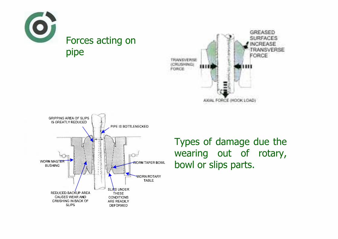
Forces acting on pipe
Types of damage due the wearing out of rotary, bowl or slips parts.

Effects of using slips that do not match size of pipe
Results of stopping pipe with slips

Results of setting slips on tool joint
Lubrication and care of rotary equipment

• To prevent mowing of the drill collar it is necessary to use so safety clamp.

• Every three months, and each time a new master bushing or rotary slips is put into service, a slip test should be performed, according to the following procedure:
1. Ensure that the hook load is 450000 Nor more to obtain a proper test.
2. Clean a section of drill pipe where no previous insert marks exist.
3. Wrap a piece of durable waterproof paper around the drill pipe.
4. Carefully place slips currently in use around the paper-wrapped section of drill pipe.
5. Lower the slips into the master bushing with normal setting speed.
6. Holding slips together by the handles, raise the pipe and carefully remove the slips.
7. Remove the paper and evaluate the markings.

• Power slips. They can be air-powered slips, or spring-assisted slips
Air-powered slips:
(1) cylinder,
(2) piston,
(3) sleeve,
(4) slips carrier,
(5) adjusting screw,
(6) adjusting plate,
(7) rotary table,
(8) master bushing,
(9) slips,
(10), (11) i (12) grease fittings

Spinning and torquing devices
• Tongs. Two sets of tongs are needed for making up a joint or breaking out joint. – They are suspended on wire rope with the counterbalance at the opposite end to enable vertical positioning of the tongs.
– The tong jaws are matched carefully to the size of the pipe or collar.
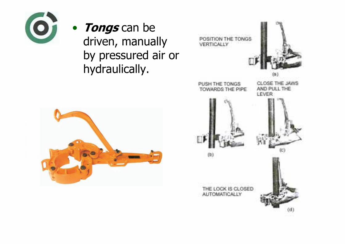
• Tongs can be driven, manually by pressured air or hydraulically.

Tongs parts
Tongs dimensions
MODEL A B C D E ST-60 52 3/4" 49 1/2" 25" 15" 5" ST-160 60" 56 1/2" 31 1/2" 19 1/2" 5"

When making up a joint it is necessary that the tong lever and the spinning line end with the angle of 90°.
Correction is also necessary if the anchoring side and the tong lever are not in the same plane (horizontal).
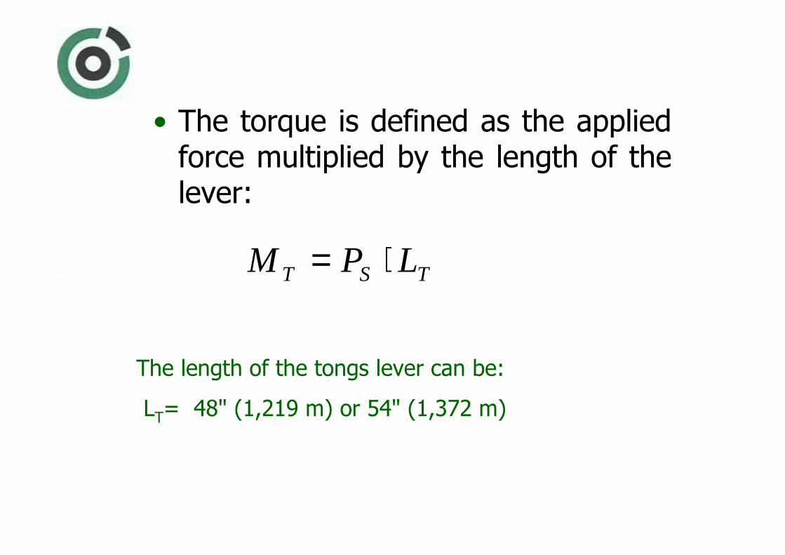
• The torque is defined as the applied force multiplied by the length of the lever:
TST LPM ⋅=
The length of the tongs lever can be:
LT= 48" (1,219 m) or 54" (1,372 m)

• If there is some kind of misalignment.
• The force that is really applied, will be less than registered:
θcos⋅= MS PP
Ps– applied force, N
PM
– registered force, N
θ – the angle of misalignment , °

Example
• Determine the really torque for drill pipe connection: 4" EU; NC 46 (4" IF)
External drill pipe diameter: D = 146,1 mm
Internal drill pipe diameter: d = 82,6 mm
Mass of a unit length in air: w = 23,36 kg/m'
Necessary torque: MT = 22700 N�m
• The force in the drag line should be:
PS = M
T/L
T = 22700/1,219 = 18622 N ; when tong lever is
LT= 1,219 m (for tong lever length, 1,372 m; P
S= 16545
N)
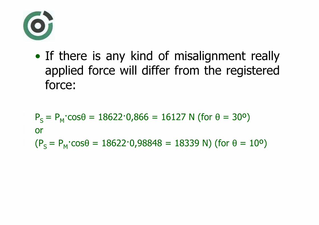
• If there is any kind of misalignment really applied force will differ from the registered force:
PS = P
M�cosθ = 18622�0,866 = 16127 N (for θ = 30º)
or
(PS = P
M�cosθ = 18622�0,98848 = 18339 N) (for θ = 10º)

Spinning chain• The spinning chain or the hemp
rope is used in making up a tool joint when tripping in the hole. – One end is first wound neatly
around the tool joint of a stand of pipe suspended in the hole.
– The other end is attached to the makeup cathead.
– When next joint is stabbed the wounds are moved up.
– The driller than uses the cathead to pull on the spinning chain or rope.

• Forces on the cathead
Force in the tong arm(T) is determined from:
ometT mmαµ ⋅⋅=
Tm
– force in the tong arm, N
t m– force that the driller is applying, N
e – natural logarithm base; 2,71828
µm
– rope (chain) to cathead coefficient of friction; 0,2
αo
– degree of the rope envelopment around the cathead; º
(in radians 2⋅π⋅αo/360°)
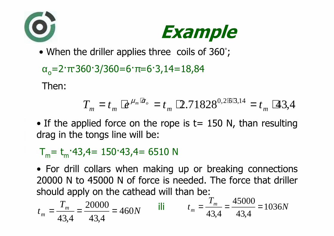
Example• When the driller applies three coils of 360°;
αo=2�π�360�3/360=6�π=6�3,14=18,84
Then:
4,4371828.2 14,362,0 ⋅=⋅=⋅= ⋅⋅⋅mmmm ttetT om αµ
• If the applied force on the rope is t= 150 N, than resulting drag in the tongs line will be:
Tm= t
m�43,4= 150�43,4= 6510 N
• For drill collars when making up or breaking connections20000 N to 45000 N of force is needed. The force that driller should apply on the cathead will than be:
NT
t mm 460
4,43
20000
4,43=== N
Tt m
m 10364,43
45000
4,43===ili

• Some other kinds of spinning and torquing devices that have been developed are: (1) kelly spinner, (2) air-powered spinning wrench (tongs)or hydraulically powered spinning wrench (tongs).
• A kelly spinner is a power device for turning the kelly when making a connection. – It is attached to the
lower part of the swivel and may be driven by either air or hydraulic motor.
VALVE ˝A˝VALVE ˝B˝
CONTROL VALVE
MUD PRESSURE LINE
LUBRICATOR
FILTER
CONTROL
VALVE
AIR TANK
DRILLERS
CONSOLE
SPINNER
TENSIONER
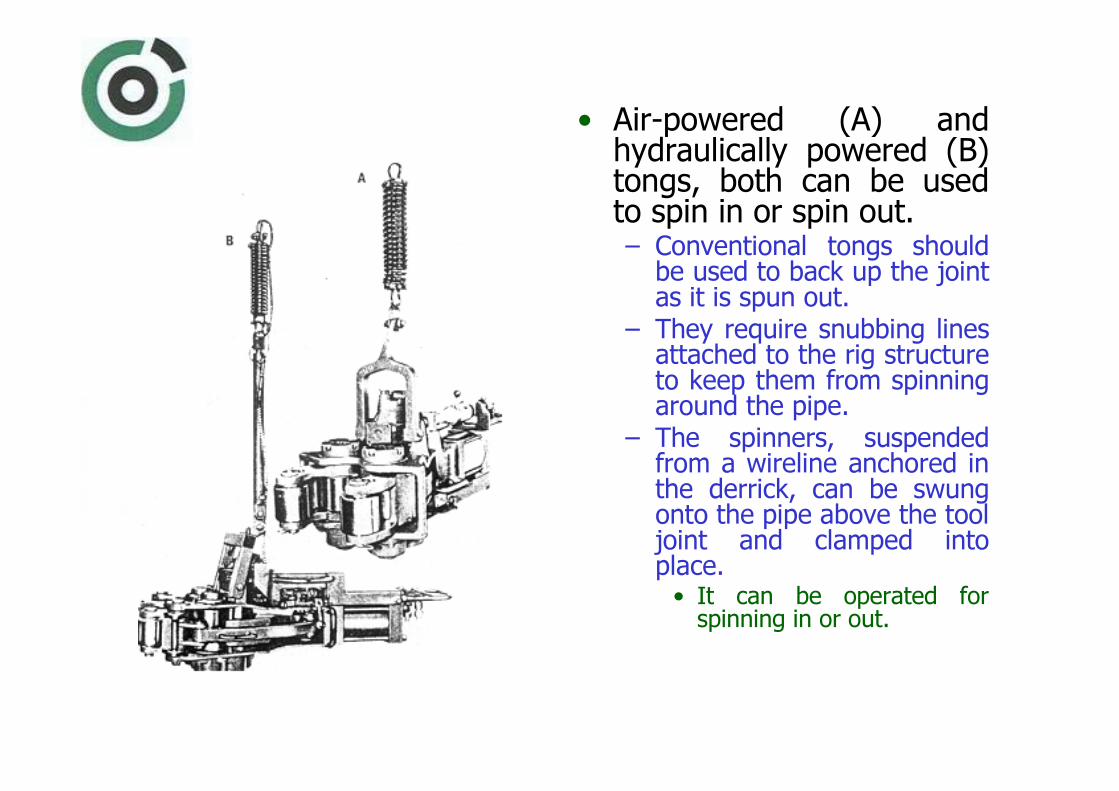
• Air-powered (A) and hydraulically powered (B)tongs, both can be used to spin in or spin out.– Conventional tongs should
be used to back up the joint as it is spun out.
– They require snubbing lines attached to the rig structure to keep them from spinning around the pipe.
– The spinners, suspended from a wireline anchored in the derrick, can be swung onto the pipe above the tool joint and clamped into place.
• It can be operated for spinning in or out.

EASY-TORQUE SPINNING
DEVICE
TOP DRIVE
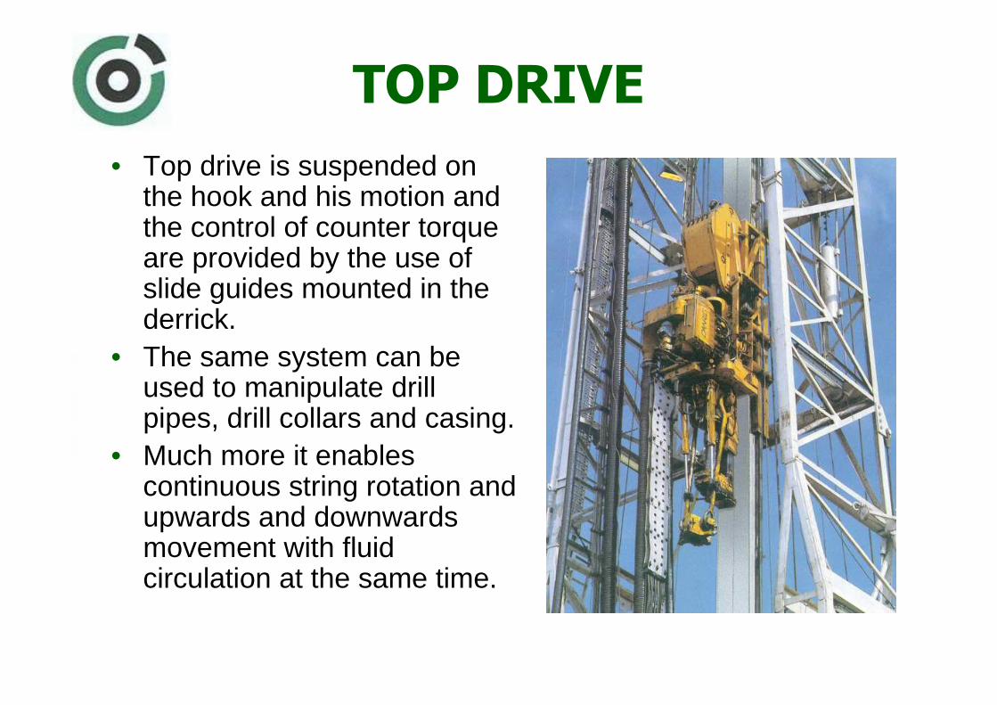
• Top drive is suspended on the hook and his motion and the control of counter torque are provided by the use of slide guides mounted in the derrick.
• The same system can be used to manipulate drill pipes, drill collars and casing.
• Much more it enables continuous string rotation and upwards and downwards movement with fluid circulation at the same time.

• Enables drilling without rotary table and kelly, – drilling with one, two
or three drill pipes in stand,
– at the same time new drill pipes can be added while drilling is in progress, and
– it can rotate the string in both directions.

Main top drive components
• Top drive consists of:1. drilling motor and swivel,
2. guides,3. spinning, and4. control system.

Drilling motor
• Motor is mowed from the axes of the drill string and the moment is converted through the gear transmit ion.
• Guides are controlling the movement of the motor over the working length, and they take over the moment of torsion due the rotation of drill string and bit.
• At the lower end of the motor the spinning device is connected, with hydraulic key and
• At the working level or attached to the structure of rotary table there are air-powered slips.
ROTATING HEAD
MAIN AXIS
BAIL BOUNCER
AUTOMATIC SAFETY
VALVE
ELEVATOR
BAIL
TORQUE KEY
TORQUE KEY
ACTUATOR
BAILS ADAPTER
TORQUE
STOPPERS

Drilling motor• Power is generated by an direct
current electromotor (motor power my be 735 kW).
• At the upper end there is the carrying bearing and the air brake.
• Transmission is accomplished by the use of two gears with transmission rate of 5,33:1.
• Small gear is on the motor axis, and greater is mounted in the slots on main axis.
• At the top of the main axis there is a swivel that enables fluid circulation from pumps to the drill string.
UPPER
BEARING
AIR BRAKE
PIN
MOTOR
RING GEAR
POWER GEAR
MAIN AXIS
MAIN AXIS
SLOTS
LOWER BEARING

• Motor and guide with bails are suspended on the bolts on the swivel.
• Gear case closes and seals the transmission and enables the lubrication of the gears, bearings and torque-key elements.
• For proper work the motor should be cooled.– For that purpose one blower
is mounted.– Blower is powered by the
alternate current electromotor.
MAIN SHAFT

Motor guideIt consists of:
− the frame with rollers− motor carrier (backing)
that is connected with main structure, and holds motor and all connections.
• Hole system is mowing along the tracks together with the guide of travelling block if necessary.

Balancing system
• Swivel and the power system are suspended on the hook over the so called balancing system. – It serves to protect the thread on the
main shaft joint when making connections or disconnecting, because it enables the movement of about 153 mm (6"), similarly as in the hook.
• It consists of two hydraulic cylinders with connecting system to attach two hydraulic actuators and hydraulic distributor.
• Hydraulic cylinders are suspended on the hook with chains to enable alignment.

Torque key
• It serves to make connections or break out connections.
• At the same time using the elevator it can serve to carry a stand of pipes inside the rig. – Whole system also includes
bail adapter (load 4900 kN), standard bails and elevator for drill pipes.
• Also there is the actuator of automatic valve and actuator for bail bouncing.
ROTATING HEAD
MAIN SHAFT
BAIL BOUNCER
SAFETY VALVE
ELEVATOR
BAIL
TORQUE KEY
SAFE VALVE
ACTUATOR
BAIL ADAPTER
TORGUE
HOLDERS
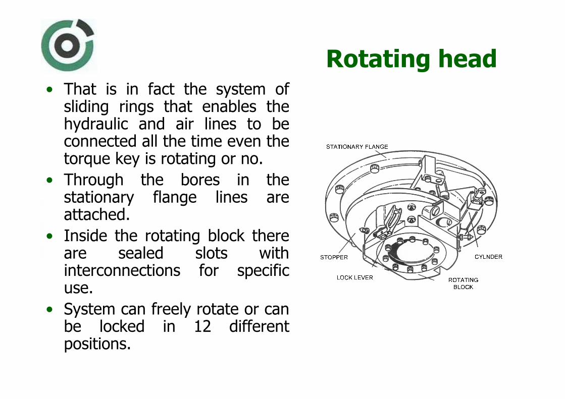
Rotating head• That is in fact the system of
sliding rings that enables the hydraulic and air lines to be connected all the time even the torque key is rotating or no.
• Through the bores in the stationary flange lines are attached.
• Inside the rotating block there are sealed slots with interconnections for specific use.
• System can freely rotate or can be locked in 12 different positions.

Bails adapter
• It connects elevator bails with motor carrier suspended on the swivel.
• Adapter is rotating together with rotating head and is freely sliding on the sleeve that is passing through.
• It has a shoulder that carries all the load of about 4900 kN, when drill pipes or casing are suspended. – It is adapted for bails with loading capacity of 2450
kN, 3430 kN and 4900 kN. – Standard drilling equipment are bails of 2743 mm
(108˝) of length and 3430 kN load capacity with standard drill pipe elevator.

Elevators bouncer• On the front side of adapter
there is a elevator bouncing mechanism that is activated by air.
• When actuator bounces the bails of 2743 mm (108˝) length, that hold elevator, it enables the elevator to receive or adjourn the pipe in the mouse hole.
• When stopped in the mean position it allows the safe work of drilling crew around the string.
BAILS
MEAN POSITION
AIR POWERED
SPRING
BAIL BOUNCING
BAILS
ADAPTER

Down-hole motors
• To enable the rotation of the bit it is also possible to use down-hole motors. In such case the rotation of entire drill string is avoided. There are three types of down-hole motors in use: turbines, Moineau motors (PDM) and electric bore engine.
• When selecting specific motor type it is necessary to consider :– available motor outer diameters,
– moment of torsion that motor can deliver and
– available power to enable motor rotation.

• According to current needs, an ideal motor should : – rotate according to allowed rotation (speed) of
chosen bit (100 to 200 revolutions per minute for roller cone bits and 250 to 1500 revolutions perminute for polycrystalline diamond bits),
– secure that the needed moment of torsion can be sustained to enable drilling to the specified rock type,
– leave enough fluid pressure to be used through the bit,
– have overall efficiency of at least 65%,– be functional regardless the drilling fluid
composition, and– be able to work in the environment with
temperature up to 180 ºC.

Turbines
• Turbine bore engine consists of a number of sections (multi-section motor), built-up of stator and rotor.
– Stator shoulder blades are mounted on the stationary part of the motor – housing.
– Rotor blades are mounted on the main motor shaft.

• Motor consists of a number of stages of stator and rotor with blades.
• Number of stages determines the power that will be exerted on the shaft.
• Drive shaft is mounted inside the housing and secured with bearings.
ROTORSTATOR
HOUSING
DRIVE SHAFT
Dr
r
H
Stator
Stator
Rotor
α
FLUID INLET
ROTATION
DIRECTION
INLET BLADES ANGLE
βOUTLET BLADES ANGLE
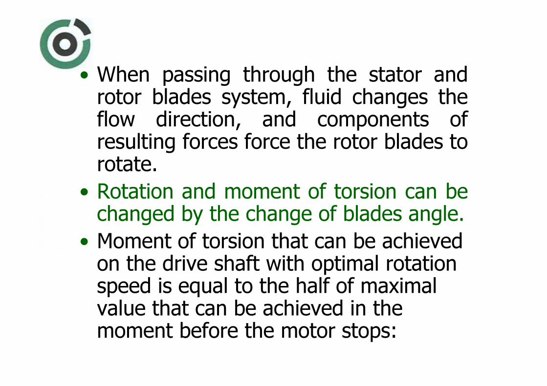
• When passing through the stator and rotor blades system, fluid changes the flow direction, and components of resulting forces force the rotor blades to rotate.
• Rotation and moment of torsion can be changed by the change of blades angle.
• Moment of torsion that can be achieved on the drive shaft with optimal rotation speed is equal to the half of maximal value that can be achieved in the moment before the motor stops:

Where:
Mt– moment of torsion, N�m
C – turbine constant
α – inlet angle, º
ns– number of stages (sections)
ρi– mud density, kg�m-3
H – blades height, m
Q – mud flow, m3�s-1
HQnCM ism
t ⋅⋅⋅⋅⋅⋅⋅= π
ραη2
tan 2

Turbine working characteristics; with constant
flow and mud density
• Power output (No) is
equal to zero when number of shaft rotations is equal zero (n=0) or when it is equal to the speed of sliding (n
r).
• Maximum power is achieved with optimal rotation speed (n
o) that is
equal to (nr/2).
η maks.
ROTATION SPEED (n)
0 no nr
N
Mt a
Mt o
pm
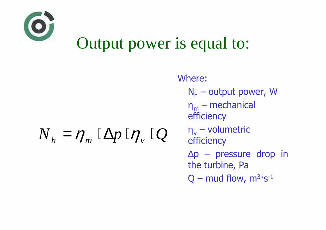
Output power is equal to:
Where:
Nh
– output power, W
ηm
– mechanical efficiency
ηv
– volumetric efficiency
∆p – pressure drop in the turbine, Pa
Q – mud flow, m3�s-1
QpN vmh ⋅⋅∆⋅= ηη
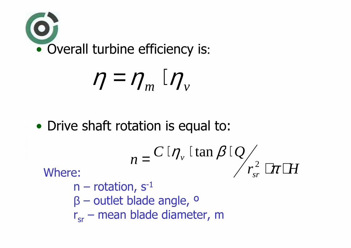
• Overall turbine efficiency is:
• Drive shaft rotation is equal to:
vm ηηη ⋅=
HrQCn
sr
v
⋅⋅⋅⋅⋅= π
βη2
tanWhere:
n – rotation, s-1
β – outlet blade angle, º
rsr– mean blade diameter, m

Moineau motor (PDM)
• Opposite of turbines Moineau motors can exert greater moment of torsion with smaller rotation speed.– They have greater overall efficiency and can supply more power to the bit.
• To do so they can also be much shorter for the same power range.
• That enables positioning of the slantwise nipples below and above the motor.
• The main parts are the helically drive shaft made of polished steel, and the housing with helically hollow stator produced of vulcanized rubber.

• They work on the inverse principle for pumps invented from French engineer Rene Moineau-a.
• To pass the working section fluid must rotate the rotor.
• Motor consists of:
– motor section,
– relief valve,
– helicoidally drive shaft,
– bearing system, and knuckle joint.
STATOR
ROTOR
d
e
BY-PASS VALVE
MOTOR
UNIVERSAL JOINT
HOUSING
BEARING
ASSEMBLY
DRIVE SHAFT

• The ratio of the length of the rotor pitch and stator pitch is the same as the ratio of number of convexities and cavities, and is called the cinematic ratio.
• Because of that motor is designated as 1/2, 3/4, 4/5, 5/6, 6/7, 7/8 or 9/10 motor.
• With greater number of convexities, number of rotations in the unit of time is smaller and the moment of torsion is greater.

• Eccentrically drive shaft rotation must be transformed to concentric bit rotation.
• That means that the bit is driven by the use of flexible knuckle joint.
UPPER JOINT
FLOW DISTRIBUTOR
ROTOR
STATOR
TRANSMISSION
UPPER RADIAL BEARING
SEALS/BEARINGS
LOWER RADIAL BEARING
DRIVE SHAFT
BIT JOINT

• Hydraulic energy is transformed in mechanical by the use of helically rotor and stator.
• When passing through the motor fluid is divided in parts and passes by forcing such cavities to prolong through the length of the stator, and to do so the rotor must rotate.

• The rotor is an external helix with a round or cycloidal cross section.
• It rotates within a stator whose internal design has one more helix than the rotor.
• The stator’s helix pitch length is equal to the rotor pitch length times the ratio of the number of stator lobes to the number of rotor lobes.
• Increasing the number of lobes, while maintaining the stator-to-rotor lobe ratio, lowers the rotor speed and increases torque within the same physical space.

Motor performance• As the fluid is pumped through
the PDM, and the tool is running free off-bottom, the pressure across the motor and bit is constant.
• As the bit touches bottom and weight is added, the fluid circulating pressure increases.
• This increase in pressure is directly proportional to the additional bit weight, or the drilling torque, and is known asthe “pressure drop” across the motor (Pm).

Motor performance• As additional weight is added,
the standpipe pressure will increase until the operating pressure drop (Pm) is reached.
• At this point the operatingtorque (To) is produced and the addition of more weight will increase the standpipe pressure and torque until a point is reached where maximum design pressure drop (Pm) is exceeded and a stall condition occurs.
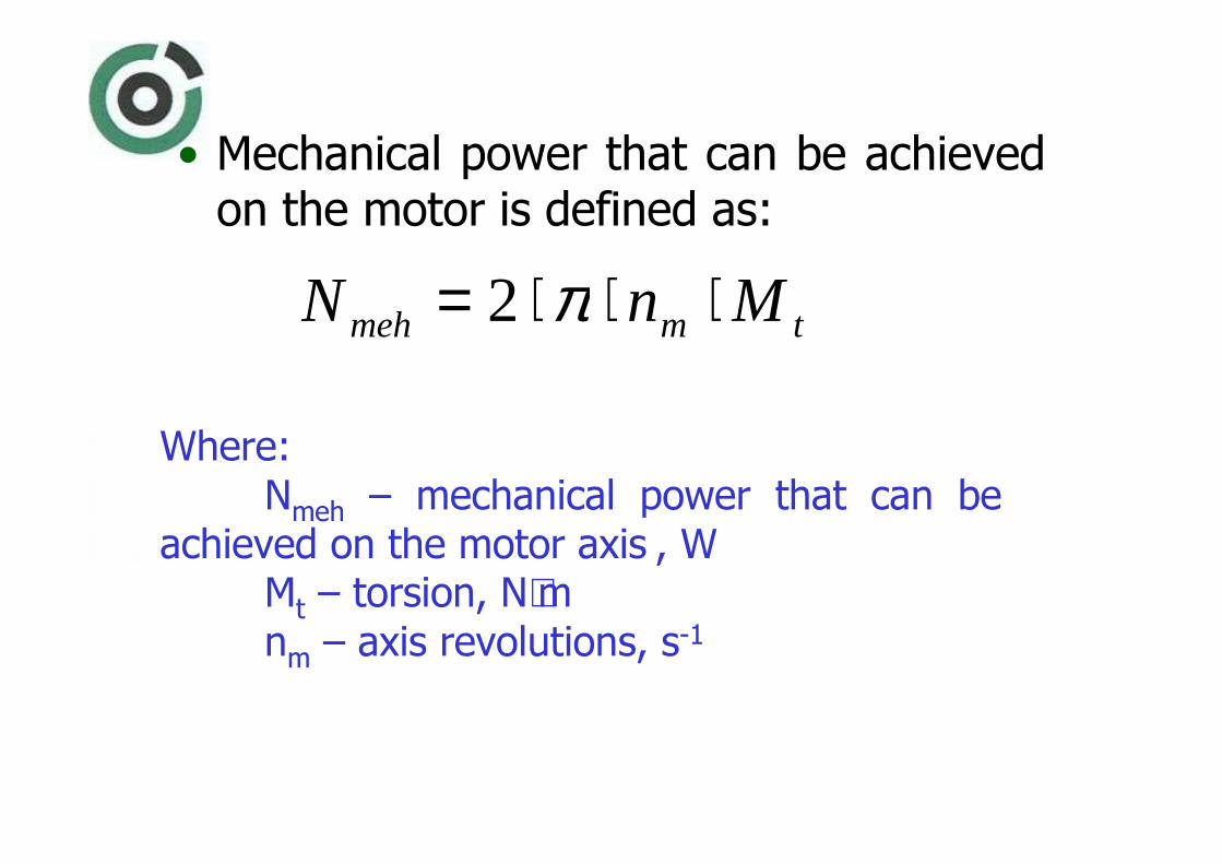
• Mechanical power that can be achieved on the motor is defined as:
tmmeh MnN ⋅⋅⋅= π2
Where:Nmeh
– mechanical power that can be achieved on the motor axis , W
Mt– torsion, N⋅m
nm– axis revolutions, s-1
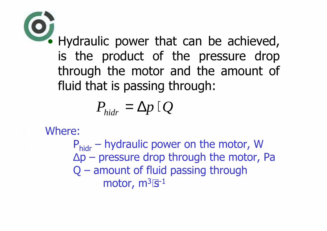
• Hydraulic power that can be achieved, is the product of the pressure drop through the motor and the amount of fluid that is passing through:
QpPhidr ⋅∆=Where:
Phidr
– hydraulic power on the motor, W∆p – pressure drop through the motor, PaQ – amount of fluid passing through
motor, m3⋅s-1
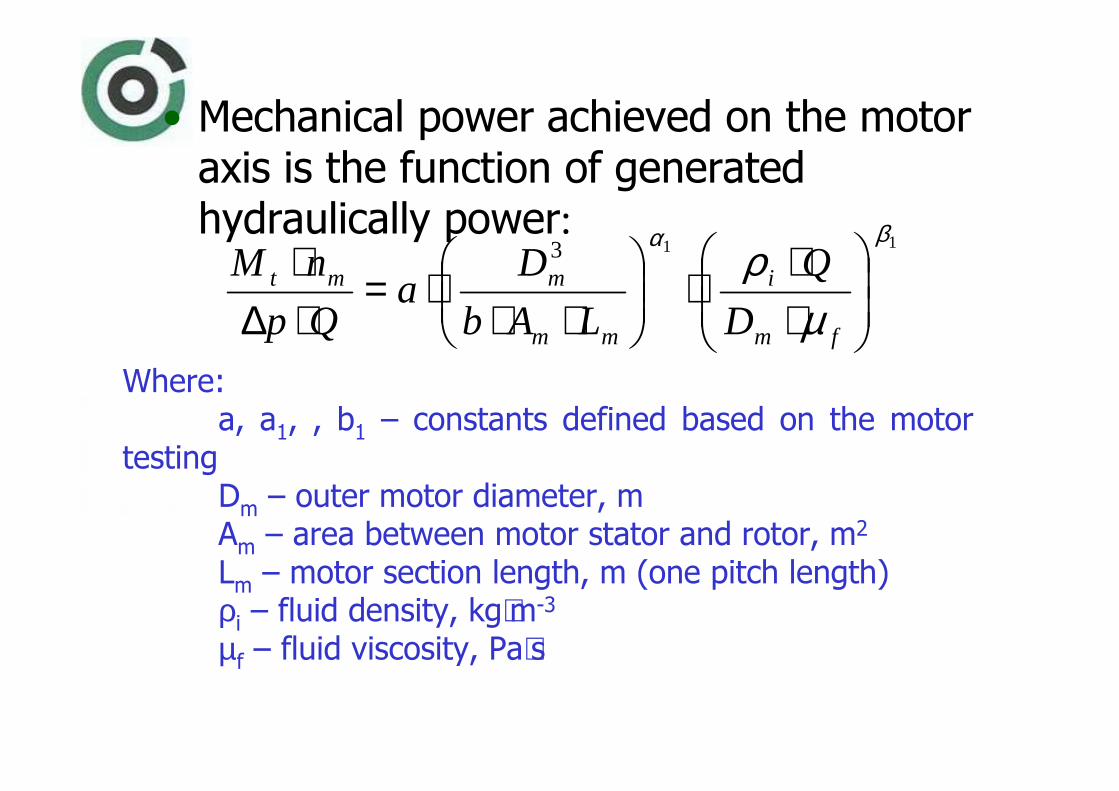
• Mechanical power achieved on the motor axis is the function of generated hydraulically power:
113βα
µρ
⋅⋅
⋅
⋅⋅⋅=
⋅∆⋅
fm
i
mm
mmt
D
Q
LAb
Da
Qp
nM
Where:a, a
1, , b
1– constants defined based on the motor
testingD
m– outer motor diameter, m
Am– area between motor stator and rotor, m2
Lm– motor section length, m (one pitch length)
ρi– fluid density, kg⋅m-3
µf– fluid viscosity, Pa⋅s

• In such way, all parameters that have impact on the work of the motor are under consideration.
• Applying results of additional testing, generalized equation is obtained.
– It can serve to determine possible moment of torsion at the motor axis, if motor geometry parameters are known:
9722,0)(391685 mmt LAbM ⋅⋅⋅=Where:
b – number (of lobes) of stator sections

Electrodrill
• The electro drill down hole motor is powered through a retrievable cable.
• As the electric drilling motor design is elastomer-less (unlike a PDM), the BHA isinsensitive to aerated or energized drilling mediums.
• Air drilling may even be considered with the electric motor.
• This facilitates the use of a full range of under balanced drilling techniques.

• Drive power is provided independent of fluid flow.• Essentially this is a control issue.
– The electric motor is controlled directly by the operator as commands are sent through the surface gear and computer.
• Speed may be increased or decreased with a joystick or set through a keyboard instruction.
• Stall may be avoided almost entirely by setting current limits in conjunction with weight on bit limits.
• As the motor approaches stall condition, a feedback loop to the CTU will automatically reduce the weight on bit to an acceptable current level.
• The system may thus be set to optimize ROP without any danger of overpowering the BHA.

• For maximum motor speeds (1200 to 3600 rpm) it will create a need for a gear box to reduce the bit rotation.
• Maximum output power can be up to 60 kW, and moment of torsion up to 215 N�m.

ECTD Setup


