9 aei105.9
30
1 9AEI105.11 1 DEPARTMENT OF TECHNICAL EDUCATION ANDHRA PRADESH Name : P. VENKAT RAO. Designation : Lecturer. Branch : Electronics and Communication Engg. Institute : Govt. Model Residential Polytechnin Gajwel. Year / Semester : I Year. Subject : Electronic Components & Materials. Subject Code : EC-105 Major Topic : Resistors. Duration : 100 Mts. Sub Topic : Rheostat and its applications. Teaching Aids : ANIMATIONS & DIAGRAMS
-
Upload
srinivas-rao -
Category
Engineering
-
view
22 -
download
0
Transcript of 9 aei105.9

19AEI105.11 1
DEPARTMENT OF TECHNICAL EDUCATION ANDHRA PRADESH
Name : P. VENKAT RAO.Designation : Lecturer.Branch : Electronics and Communication Engg.Institute : Govt. Model Residential Polytechnin Gajwel.Year / Semester : I Year.Subject : Electronic Components & Materials. Subject Code : EC-105Major Topic : Resistors. Duration : 100 Mts.Sub Topic : Rheostat and its applications.Teaching Aids : ANIMATIONS & DIAGRAMS

29AEI105.11 2
On the completion of this topic, you would be able to learn the following:
• What is a Rheostat ?
• The diagram of a Rheostat.
• The specifications and applications of Rheostats.
Objectives

39AEI105.11 3
In the previous topic, you have learnt about the following points:
• The comparison between Carbon and Wire – wound
Potentiometer.
• The need for tapering in Potentiometers.

49AEI105.11 4
Rheostat
• A rheostat is a multi-(two)terminal variable resistor.
• Rheostats are designed to handle much higher voltage and current.

59AEI105.11 5
Rheostat – Circuit symbol
Or1
2 1
3
2
Fig 1

69AEI105.11 6
Cylindrical and Circular Rheostats
Fig 2

79AEI105.11 7
A high power toroidal wire wound Rheostat
Fig 3

89AEI105.11 8
Construction of a Rheostat
• Rheostats are constructed as a resistive wire
• wrapped to form a toroid coil with the wiper moving
• over the upper surface of the toroid, sliding from
• one turn of the wire to the next.

99AEI105.11 9
Construction of a Rheostat
• Sometimes a rheostat is made from resistance wire
• wound on a heat resisting cylinder with the slider made
• from a number of metal fingers that grip lightly onto a
small portion of the turns of resistance wire.

109AEI105.11 10
Construction of a Rheostat
• The 'fingers' can be moved along the coil of resistance
wire by a sliding knob thus changing the 'tapping' point.
• They are usually used as variable resistors rather than
variable potential dividers.

119AEI105.11 11
Rheostat with various ratings and sizes
Fig 4

129AEI105.11 12
Rheostat with various ratings and sizes
Fig 5

139AEI105.11 13
Rheostat with various ratings and sizes
Fig 6

149AEI105.11 14
Rheostat with various ratings and sizes
Fig 7
159AEI105.11 15
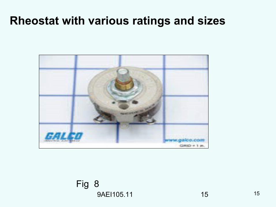
Rheostat with various ratings and sizes
Fig 8
169AEI105.11 16
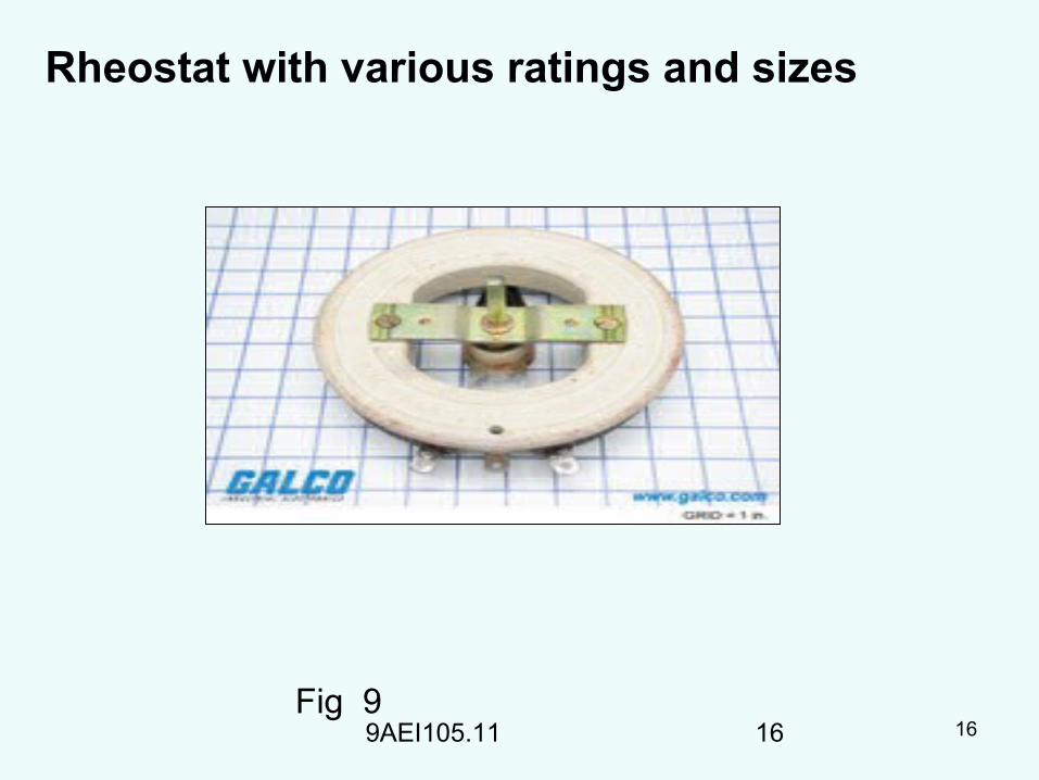
Rheostat with various ratings and sizes
Fig 9

179AEI105.11 17
Rheostat with various ratings and sizes
Fig 10

189AEI105.11 18
Rheostat with various ratings and sizes
Fig 11

199AEI105.11 19
Rheostat with various ratings and sizes
Fig 12

209AEI105.11 20
Rheostat construction
• A rheostat is constructed by winding a resistance wire
around a former.
• The former can be round and flat or cylindrical.
• A wiper blade is then arranged to touch the surface of the
resistance wire, and is made to be moveable.
• Power is supplied to both ends of the resistance wire, and a
wire is attached to the slider.

219AEI105.11AEI105.14 21
Rheostat and its construction
• The voltage at the slider wire is determined by the position of the slider on the resistance wire.
• By moving the sliding connection along the winding the resistive wire is made effectively longer ( or shorter) thus increasing ( or
reducing) the resistance in the circuit to which it is attached.
• If both ends of the winding are used and the central slider (tapping) is still connected then as one side gets shorter ( lower resistance ) the other gets longer ( higher resistance) and a voltage or potential divider is formed.

229AEI105.11 22
Rheostat and its construction
• A rheostat consists of nichrome wire resistors connected in series or parallel and connected to wound rotor of motors by slide wire contacts.
• The resistors are encased in a metal housing where it is immersed in transformer oil coolant.
• During start up of motors, the rheostat is set at maximum resistance.

239AEI105.11 23
Rheostat and its construction
• Gradually the setting is increased reducing the resistance connected to the rotor such that the motor speed also increases.
• Finally, the resistance is zero when the wiper contacts are short-circuited at the last stage and the motor rotates at rated rpm.
• Rheostats are used in wound rotor motors to reduce its starting torque and current.
• Rheostats can still be used as dimmers of lighting circuits.

249AEI105.11 24
Specifications of Rheostats
• Resistance value : 1 Ω to 10 K Ω
• Power ratings : 100 watts
• Temperature : withstand up to 300 degrees centigrade

259AEI105.11 25
Applications
• Used in Heater and Oven controls.
• Used in Light dimming controls.
• Used in speed control of DC motors.
• Used in arc welding process.
269AEI105.11 26
Summary
In this topic , you have learnt about the following points:
1. Definition of Rheostat.
2. Construction of a Rheostat.
3. Specifications and Applications of Rheostats.

279AEI105.11 27
QUIZ
289AEI105.11 28
1). A Rheostat is a ________ terminal electrical
device
a. Two
b. Three
c. Four
d. Five

299AEI105.11 29
2). A Rheostat is designed to handle
a. Low currents
b. High currents
c. Low and high voltages
d. High currents and high voltages.

309AEI105.11 30
Frequently asked questions
• What is meant by a Rheostat ?
• Describe the construction of a Rheostat.
• Mention the applications of a Rheostat.
• List the specifications of a Rheostat.

![9...U _ | 9 9 Z ~ ~ 9 9 l ~ F | z ~ 9 z } 9 b ~ ~ z 9 k ~ z U 9 9 9 f b s h ` n \ a b E 9 m G E 9 f n g ^ l Z ] Z E 9 r G 9 z } 9 d Z p Z g h E 9 g G 9 9 9 9 9 9 9 9 9 9 9 9 9 9 9](https://static.fdocuments.us/doc/165x107/5ec43ef69f2c1a7c0e286bb4/9-u-9-9-z-9-9-l-f-z-9-z-9-b-z-9-k-z-u-9-9-9-f-b-s-h-.jpg)

![[XLS]servicioscompartidos.uniandes.edu.co · Web view2 4 6 9 6 9 6 9 6 9 6 9 9 9 9 9 9 7 9 9 9 9 9 7 9 7 9 7 9 4 6 9 9 9 9 9 4 6 9 4 6 9 4 6 9 4 6 9 6 9 4 6 9 9 9 9 9 4 6 9 9 9 9](https://static.fdocuments.us/doc/165x107/5be14b3a09d3f232098d2967/xls-web-view2-4-6-9-6-9-6-9-6-9-6-9-9-9-9-9-9-7-9-9-9-9-9-7-9-7-9-7-9-4-6.jpg)