8x4 SpaceSaver Garden Shed Assembly Manual · 8x4 SpaceSaver Garden Shed Assembly Manual Thank you...
30
Toll Free 1-888-658-1658 www.outdoorlivingtoday.com [email protected] Page 1 8x4 SpaceSaver Garden Shed Assembly Manual Thank you for purchasing an 8x4 SpaceSaver Garden Shed. Please take the time to identify all the parts prior to assembly. Safety Point s and Other Considerations Our products are built for use based on proper installation and normal residential use, on level ground. Please follow the instruction manual when building your shed and retain the manual for future maintenance purposes. Some of the safety and usage measures you may wish to consider include: -snow load ratings vary by geographical location. If heavy or wet snowfall occurs, it is advisable to sweep the snow off the roof(s). -if the product is elevated, any structural and building code requirements are solely the customer's responsibility, and should be abided by. -in high or gusty wind conditions it is advisable to keep the structure securely grounded. -have a regular maintenance plan to ensure screws, doors, windows and parts are tight. Customer agrees to hold Outdoor Living Today Partnership and any Authorized Dealers free of any liability for improper installation, maintenance and repair. Revision #8 July 5, 2010 In the event of a missing or broken piece, simply call the Outdoor Living Today Customer Support Line @ 1-888-658-1658 within 30 days of the delivery of your purchase. It is our commitment to you to courier replacement parts, free of charge, within 10 business days of this notification. Replacement parts will not be provided free of charge after the 30 day grace period.
-
Upload
truongdiep -
Category
Documents
-
view
224 -
download
1
Transcript of 8x4 SpaceSaver Garden Shed Assembly Manual · 8x4 SpaceSaver Garden Shed Assembly Manual Thank you...

Toll Free 1-888-658-1658 www.outdoorlivingtoday.com [email protected] 1
8x4 SpaceSaverGarden Shed
Assembly Manual
Thank you for purchasingan 8x4 SpaceSaver Garden Shed. Please take the time to identify all the parts prior to assembly.
Safety Points and Other ConsiderationsOur products are built for use based onproper installation and normal residentialuse, on level ground. Please follow the instruction manual when building your shed and retain the manual for future maintenance purposes.
Some of the safety and usage measures you may wish to consider include:
-snow load ratings vary by geographical location. If heavy or wet snowfall occurs, it is advisable tosweep the snow off the roof(s). -if the product is elevated, any structural and building code requirements are solely the customer's responsibility, and should be abided by. -in high or gusty wind conditions it is advisable to keep the structure securely grounded. -have a regular maintenance plan to ensure screws, doors, windows and parts are tight.
Customer agrees to hold Outdoor Living Today Partnership and any Authorized Dealersfree of any liability for improper installation, maintenance and repair.
Revision #8July 5, 2010
In the event of a missing or broken piece, simply call the Outdoor Living TodayCustomer Support Line @ 1-888-658-1658 within 30 days of the delivery of your purchase. It is our commitment to you to courier replacement parts, free of charge, within 10 business days of this notification. Replacement parts will not be provided free of charge after the 30 day grace period.

Thank you for purchasing our 8x4 SpaceSaver Garden Shed.Please take the time to identify all the parts prior to assembly.
Parts List:A. Floor Section 1 - 45 ½” x 75” Large Floor Joist Frame (2 Joists Unattached) 1 - 45 ½” X 21” Small Floor Joist Frame (2 Joists ATTACHED)2 - 1 ½” x 3 ½” x 72” Floor Joists5 - 1 ½” x 3 ½” x 45 ½” Floor Runners1 - 5/8” x 45 3/8” x 74 7/8” Plywood1 - 5/8” x 45 3/8” x 20 7/8” Plywood
B. Wall Section4 - 45 ½” x 75” Wall Panels1 - 45 ½” x 75” Window Wall Panel1 - 12” x 73” Narrow Wall Panel2 - 9” x 45 ½” Wall Extendors2 - 45 1/4” Angled Wall Extendors 4 - 1 ½” x 2 ½” x 45 1/2” Wall Plates1 - ¾” x 3 ½” x 70” Horizontal Wall Cleat1 - ¾” x 3 ½” x 21” Horizontal Wall Cleat
Door, Jambs & Header1 - 31” X 72” Full Door1 - 1 ½” x 3” x 73” Door Jamb1 - 2” x 3” x 45 ½” Door Header (Dado cut on edge)
C. Rafter & Roof Section2 - Roof Panels 51 ½” x 55 ¾” (1-Left 1- Right )6 - 1 ½” x 2 ½” x 54” Rafters2 - ½” x 4” x 48” Front Soffit2 - ½” x 3” x 48” Rear Soffit4 - Filler Shingles - 5 1/2” Wide 1 - 8”x 96” Strip of Roofing Felt
D. Miscellaneous Section(Skirting, Facia ,Trim & Misc. Parts)2 - ½” x 4” x 54 1/8” Side Angle Cut Facia2 - ½” x 4” x 50” Front Facia2 - ½” x 4 ½” x 50” Rear Facia6 - ½” x 4 ½” x 45 1/4” Bottom Skirting4 - ½ x 2 ½” x 75” Corner Filler Trim2 - ½” x 2 ½” x 78 ¾” Vertical Door Trim2 - ½” x 2 ½” x 80” Front Side Corner Trim4 - ½” x 2 ½” x 88 ¾” Rear/Middle Trim (Opt. Door Trim)2 - ½ x 4 ½” x 78 ¾” Front Corner Trim2 - ½” x 4 ½” x 88 ¾” Rear Corner Trim1 - ½” x 1 ¾” x 32” Horizontal Door Trim1 - ½” x 2 1/2” x 8 1/2” Horizontal Narrow Wall Trim2 - ½” x 4” x 51 5/8” Roof Ridge Board2 - Detail Facia Plate (Larger for Rear Facia)1 - Window Insert1 - Flower Box Kit
(Assembly Instuctions and Hardware found in Kit)2 - ½” x 2 ½” x 72” Interior Vertical Door Stops1 - ½” x 2 ½” x 35 ¼” Interior Horizontal Door Stop1 - 45 ¼” Extra Piece of Wall Siding
Important:The SpaceSaver Shed can be assembled in many different configurations. This Assembly Manualillustrates the most common configuration with the door to the left front 8ft side and Window Wall toright front 8 ft side. If you choose to configure with Door on end (45 1/2” side) , please refer to end of the AssemblyManual for required changes necessary to correctly assemble.
Note: Standard Sheds come with 1 Window Wall Panel. On all configurations, the Window WallPanel can be positioned in any location to best suit purchasers preference.
Toll Free 1-888-658-1658 www.outdoorlivingtoday.com [email protected] 2

8x4 SPACESAVER HARDWARE PACKAGE
Note: screws and nails shown actual size.
Tee Hinge x 3 Door Handle
Hardware Kit (Provided)
Safety Glasses Work Gloves
Safety Equipment Required (Not Provided)
Ladder
Screw Gun/Drill Tape MeasureHammer Wood Clamp
Level Pliers
Tools Required (Not Provided)
1/8” Drill Bit
Barrel Bolt
Utility Knife
Simpson StrongTie x 8
Toll Free 1-888-658-1658 www.outdoorlivingtoday.com [email protected] 3
1 1/4” Finishing
Square Drive Bit
2 1/2”
1 1/4”
3/4”Black
2” Black
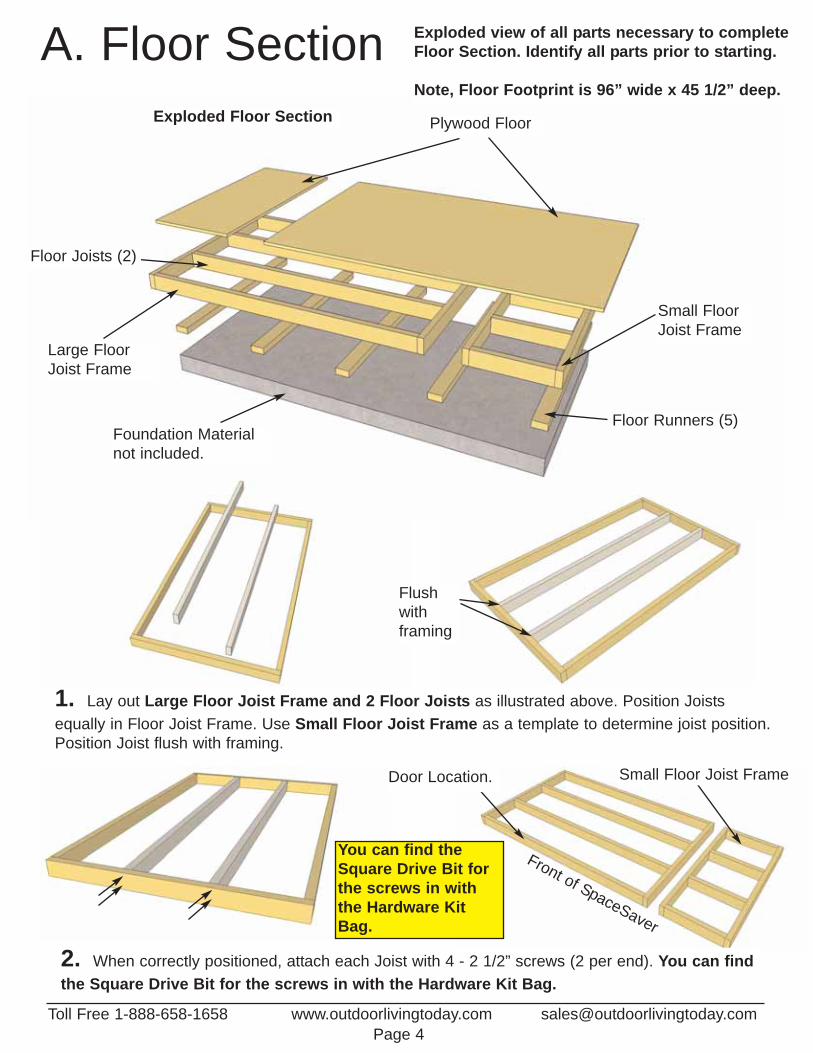
Plywood Floor
Large FloorJoist Frame
Floor Joists (2)
Floor Runners (5)
Small FloorJoist Frame
Exploded Floor Section
A. Floor Section Exploded view of all parts necessary to complete Floor Section. Identify all parts prior to starting.
Note, Floor Footprint is 96” wide x 45 1/2” deep.
Foundation Materialnot included.
1. Lay out Large Floor Joist Frame and 2 Floor Joists as illustrated above. Position Joists equally in Floor Joist Frame. Use Small Floor Joist Frame as a template to determine joist position.Position Joist flush with framing.
2. When correctly positioned, attach each Joist with 4 - 2 1/2” screws (2 per end). You can findthe Square Drive Bit for the screws in with the Hardware Kit Bag.
Flushwithframing
Front of SpaceSaver
Door Location. Small Floor Joist Frame
You can find theSquare Drive Bit forthe screws in withthe Hardware KitBag.
Toll Free 1-888-658-1658 www.outdoorlivingtoday.com [email protected] 4

3. With Floor Joist Frames positionedtogether flush, attach with 6 - 2 1/2”screws.
4. Position and attach Floor Runners to completed floorframes with 6 - 2 1/2” screws per Runner. Make sureRunners are flush with outside, front and rear floor framing,but not overhanging. Make sure 4th Runner is placedequally over seam where floor frames meet.
4th Runner
4th Runner
96”
45 1/2”
5. With Floor Runners attached, carefully flip the floor over and place on your foundation. Caution- you may need 2 people to assist you. Be careful when laying floor down not to bend or twistfloor. Note: The floor will be flipped over and floor runners will sit on your foundation. It is important tonote that having a level foundation is critical. Choosing a foundation will vary between regions. Typicalfoundations can be concrete pads or patio stones positioned underneath the floor runners.
6. When in place, level floor completelybefore proceeding.
7. Position Plywood Floor pieces (2) on top ofcompleted floor joists.
Flush with Floor Framing
Front
Toll Free 1-888-658-1658 www.outdoorlivingtoday.com [email protected] 5
To help level Floor, locate Shim Shingles (used inpackaging) found in the edges of each Roof Panel.
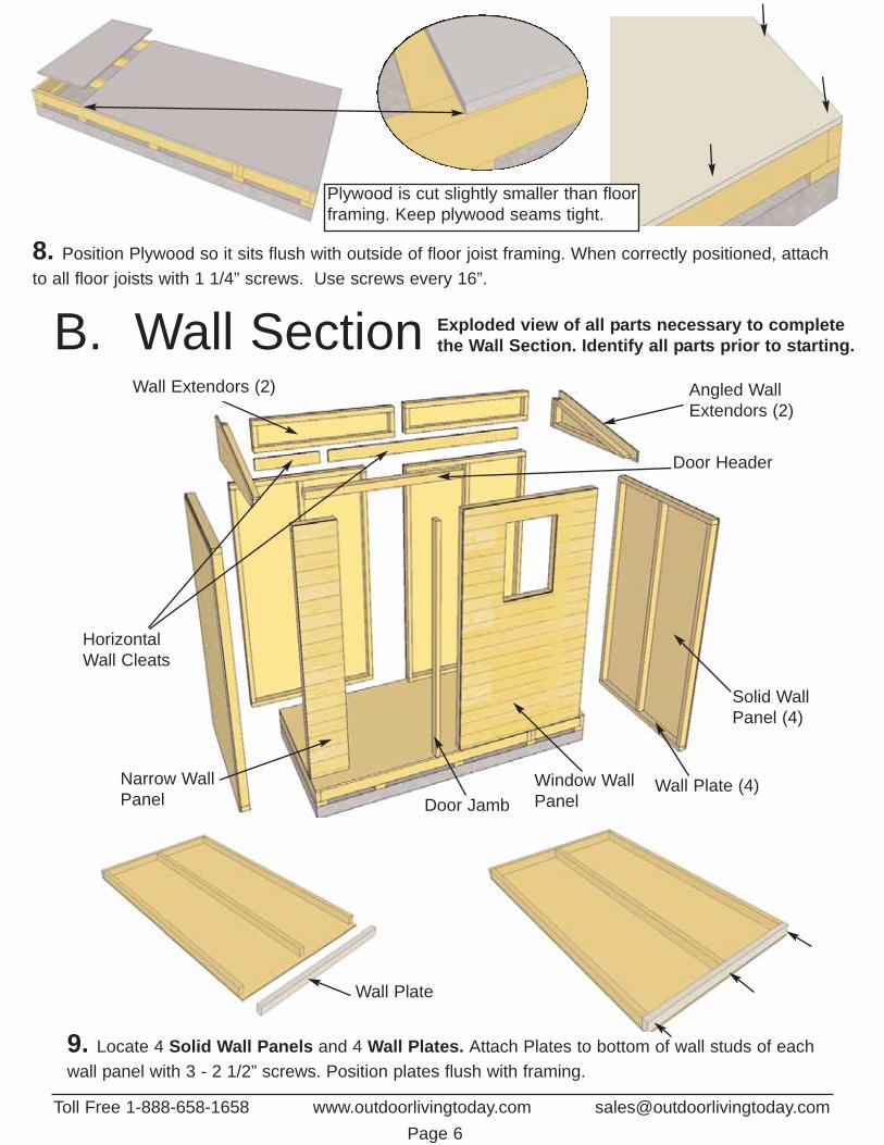
B. Wall Section Exploded view of all parts necessary to complete the Wall Section. Identify all parts prior to starting.
Angled WallExtendors (2)
Door Header
Solid Wall Panel (4)
Wall Plate (4)Window WallPanelDoor Jamb
Narrow WallPanel
HorizontalWall Cleats
Wall Extendors (2)
Wall Plate
9. Locate 4 Solid Wall Panels and 4 Wall Plates. Attach Plates to bottom of wall studs of eachwall panel with 3 - 2 1/2” screws. Position plates flush with framing.
Toll Free 1-888-658-1658 www.outdoorlivingtoday.com [email protected] 6
8. Position Plywood so it sits flush with outside of floor joist framing. When correctly positioned, attachto all floor joists with 1 1/4” screws. Use screws every 16”.
Plywood is cut slightly smaller than floorframing. Keep plywood seams tight.

10. Starting on Side, position a Solid Wall Panel on top of plywood floor. TheWall Panel bottom framing will sit flush with floor framing. Wall siding will overhang the floor. Important: Make sure all walls are aligned in their uprightposition. If not ,water may leak into your shed. Unsure if panel is facing up ordown? Recently attached Bottom Plate is on bottom of panel.
11. Outside 2x3 framing of wall panel should be flush with outside of floor framing when properly aligned. The Plywood is cut slightly smaller than floor framing. Keep plywood seams tight.Note: Siding will overhang the floor by approx. 1/2”. When positioned correctly, locate 2nd Solid WallPanel and place in Corner.
Wall Plate Flushwith floor framing
WallSidingOverhangsFloor by1/2”
12. Butt both vertical wall studs of side and rear walls together and attach with 3 - 2.5” screws.Screw at the bottom, middle and top of stud to secure properly. Note, drill pilot holes in studs to prevent splitting.
Rear Sold Wall
Side
Solid
Wal
l
Optional - Caulkingseams will help preventmoisture from enteringat seam. Caulking notincluded in kit.
Do Not Attach WallsTo Floor until Step 30
Toll Free 1-888-658-1658 www.outdoorlivingtoday.com [email protected] 7
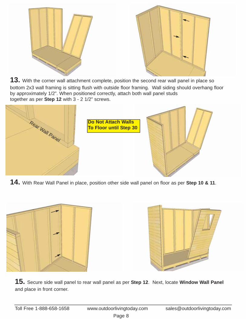
13. With the corner wall attachment complete, position the second rear wall panel in place so bottom 2x3 wall framing is sitting flush with outside floor framing. Wall siding should overhang floorby approximately 1/2”. When positioned correctly, attach both wall panel studs together as per Step 12 with 3 - 2 1/2” screws.
14. With Rear Wall Panel in place, position other side wall panel on floor as per Step 10 & 11.
Rear Wall Panel
15. Secure side wall panel to rear wall panel as per Step 12. Next, locate Window Wall Paneland place in front corner.
Do Not Attach WallsTo Floor until Step 30
Toll Free 1-888-658-1658 www.outdoorlivingtoday.com [email protected] 8

16. Align front corner Window Wall Panel as per Steps 11 & 12. using 3 - 2 1/2” screws to secure wall studs together.
17. Locate Narrow Wall Panel and position once again so 2x3 bottom wall framing sits flush onfloor and wall siding overhangs. Note, Narrow Wall Panel is only 73” high.
18. Secure as per Step 12. 19. Locate 3” wide Door Jamb and place onwall stud to the right where door to be located.
Door Jamb
Toll Free 1-888-658-1658 www.outdoorlivingtoday.com [email protected] 9

20. Position Door Jamb flush against wall stud and floor. The Jamb is 3” wide and will sit flush tooutside of wall siding. When positioned correctly, secure Jamb using 4 - 2 1/2” screws.
21. Position and attach the Door Header to Door Jamb and Narrow Wall Panel top framing.Header should sit flush with Door Jamb and Outside of Narrow Wall Panel Siding. Attach with 3 - 2 1/2” screws.
Dado cut on edge
22. Locate a Angled Wall Extendor and place on side wall panel frame. Note, lap siding of Wall Extendor will cover lap siding of side wall.
Lap Sidingof panels willfit together.
Toll Free 1-888-658-1658 www.outdoorlivingtoday.com [email protected] 10

23. Align siding of Angled Wall Extendor and Side Wall so they are flush. Note, When correctly aligned, vertical rear framing of Angled Gable Wall will overhang Side Wall framing by approx. 1/2”.
24. With Angled Wall Extendor and Side Wall aligned correctly, secure together from the insidewith 4 - 2 1/2” screws.
25. Complete opposite Angled Wall Extendor positioning and attachment as per Step 23 & 24.
Extendor Framingoverhangs WallFraming by 1/2”
Sidinglines up Slight Gap
Toll Free 1-888-658-1658 www.outdoorlivingtoday.com [email protected] 11

26. Locate one Wall Extendor and place on rear wall panel with lap siding of extendor overlapping that of the rear wall.
Lap siding ofExtendor Wall
Lap Sidingof rear wall.
27. With 2x3 wall framing aligned, attach Wall Extendor to both the Angled Wall Extendor framingand the rear wall framing with 5 - 2 1/2” screws.
28. Position and secure 2nd Wall Extendor Panel as per Steps 26 & 27. Attach together with 2 - 2 1/2” screws.
Toll Free 1-888-658-1658 www.outdoorlivingtoday.com [email protected] 12

29. Attach Horizontal Wall Cleats to Wall Extension bottom framing and rear wall top framing so cleatis flush with extension framing. There is a short and long wall cleat. Alternate alignment of screws so 1/2screw into wall extension framing and the other land in the rear wall top framing. Use 8 - 1 1/4” screws.
30. To complete WallSection, attach bottom 2x3wall plates to plywood floorwith 22 - 2 1/2” screws.Confirm Doorway opening is32” wide. Prior to securing,make sure wall panels arealigned correctly on the floor.Refer to Step 11. Wall sidingshould overhang floor while2x3 wall plates should sitflush with floor.
C. Rafter and Roof SectionExploded view of all parts necessary to complete the Rafter and Roof Section. Identifyall parts prior to starting. 5 1/2” Wide Filler Shingles not shown in Illustration.
Left RoofPanel
Right RoofPanel
Rear Soffit (2)3” wide
Rafter (6)
Front Soffit (2)4” wide
Simpson StrongTies (8)
Caulking
Bottom Wall
Optional - Caulkingseams will help preventmoisture from enteringat seam. Caulking notincluded in kit.
ConfirmDoorway opening is 32” wide.
Toll Free 1-888-658-1658 www.outdoorlivingtoday.com [email protected] 13

Toll Free 1-888-658-1658 www.outdoorlivingtoday.com [email protected] 14
31. Locate 6 Rafters, 2 Front 4” wide Soffits and 2 Rear 3” wide Soffits.Lay out on level ground as shown in Illustration (A) below. Attach end ofa 48” long Soffit Boards flush to ends of outside rafter with 2 - 1 1/4”screws per rafter end. Important- Drill pilot holes in Soffit ends to preventsplitting. Measure and attach interior Rafters as illustrated below in (B).Measure and attach remaining Soffit / Rafter connections using 2 -1 1/4”screws per rafter/soffit. See Illustration (C).
4” wide
3” wide
3” wide Rear Soffit Board (2)
4” wide FrontSoffit Board (2)
48”
21 3/4”
21 3/4”
96”
A. B.
C.
Front Soffit
Mid Rafter Mid Rafter
Front
Confirm Rafter angle
3” wide Soffit
Screw center rafters togetherwith 3 - 2 1/2” screws

32. Carefully flip completed Rafter Section over so 4” wide Soffit is facing the front and place onSpaceSaver walls. Note, once again, make sure 4” wide Soffit is positioned to the front of the shed.
33. Position Rafter Section on walls so outside Rafters lay flush with gable framing equally fromside to side and both Front and Rear Soffits are flush against both front and back walls.
34. When Rafter Section is positioned correctly, both Front and Rear Soffits will sit flush againstsiding of wall panels.
3” wide Soffit4” wide Soffit
Rear of SpaceSaver
Front of SpaceSaver
Toll Free 1-888-658-1658 www.outdoorlivingtoday.com [email protected] 15

35. With Rafter Section correctly aligned, secure rafters to walls using Simpson Strong TieConnectors. Start with outside rafters and secure 2- strong ties with 1 1/4” screws. Screw into WallExtension Framing at the rear and the Wall Panel top framing at the front. Complete both sides.
Simpson StrongTie Connectors
36. With outside rafters properly secured, completely secure remaining interior rafters using 3 - 2 1/2”Screws per side. Screw from inside of Top Wall Plate into Rafter.
37. Correctly orientate Left Side Roof Panel with shingles overhanging roof battens on the outsideleft and shingles flush with battens to the right. Place on rafters with front roof batten flush with frontof rafter. Note, trimmed shingles on roof panel to back of shed.
Shingles overhang roofbattens on outside. Front batten flush
with rafter end.
Battens flushwith shingles.
Toll Free 1-888-658-1658 www.outdoorlivingtoday.com [email protected] 16

Attach above theexposure line.
40. Roof Filler Shingles are included to cover roof seams. Starting at the bottom, slide the first Longshingle in until flush with other bottom shingles. Screw first filler shingle down to rafters using 1 - 2 1/2” screw per panel (2 in total). Make sure to screw into both rafters.
38. For correct Roof Panel position, align panel so roof batten sits evenly on center Rafter. Completeboth roof Panels
ExposureLine
39. With Roof Panel aligned, screw panels down to center rafter with 2 - 2 1/2” screws in the bottom row of shingles. (1 screw per panel)
Roof Seam
Toll Free 1-888-658-1658 www.outdoorlivingtoday.com [email protected] 17
Roof Panel centered on rafter.
Screw BottomRow of ShinglesOnly for now.

41. Slide in another Long FillerShingle and attach as per Step 40.On your last Filler Shingle, attach toroof with 2 - 1 1/4” finishing nails.
42. Secure roof panels to walls at both ends by positioning 2 Simpson Strong Ties on battens and outside rafters and securing with 4 - 1 1/4” screws per Strong Tie. Complete both sides.
Strong Ties
43. To further secure roof panels, from the inside, drill pilot holes in each Mid Rafters (3 per Rafter) onan angle. Using 3 - 2 1/2” screws, secure rafters to roof battens. Note, from outside, push roof paneldown so batten sit flush against rafter when securing.
Mid
Rafter
Roof Batten
3 - 2 1/2” screws ToeNailed in each Mid Rafter
Toll Free 1-888-658-1658 www.outdoorlivingtoday.com [email protected] 18

D. Miscellaneous SectionExploded view of all parts necessary to complete the Skirting, Trim, Facia and all Miscellaneous Pieces.Identify all parts prior to starting. (Not Shown; Interior Door Stops, Rear Trim, Horizontal Door Trimand Roofing Felt)
Rear Facia (2)Roof Ridge Boards (2)
Side Skirting(2)
Window Insert
Flower Box
Side Angle Cut Facia (2)
Front SideCorner Trim (2)
Front CornerTrim (2)
Corner FillerTrim (4)
Front & RearSkirting (4)
Full Door
Black TeeHinge (3)
DoorHardware
Vertical DoorTrim (2)
Facia Detail Plate
Front Facia (2)
44. Attach Bottom Skirting around the base of the shed. Skirting will hide floor framing. Start withside skirting pieces first and attach with 4 - 1 1/4” finishing nails per piece.
Toll Free 1-888-658-1658 www.outdoorlivingtoday.com [email protected] 19

45. Rear skirting pieces will meet together in the center. Secure with 4 - 1 1/4” finishing nails per piece.
46. Gaps on outside will be covered by Corner Trim pieces later. Complete front and side skirtingattachments.
47. Use 6 nails on front skirting piecewhere door will be installed later for extra support since it will be a high traffic area. 48. Locate Corner Filler Trims (2 - 1/2” x 2 1/2” x 75”)
and place in front corners of SpaceSaver.
Rear Skirting
Gap
SideSkir
ting
Skirting meets flush in center
Corner FillerTrim.
Toll Free 1-888-658-1658 www.outdoorlivingtoday.com [email protected] 20

49. Attach Corner Filler Trims where gaps exist in front corners. Hammer with 8 - 1 1/4” finishingnails. Corner Fillers are positioned flush with siding and to the top of the bottom skirting.
50. Position and attach Corner Filler Trims in the rear as per Step 49.
AngledExtendor Wall
Corner FillerTrim
51. Locate Vertical Door Trims - (2 - 1/2” x 2 1/2” x 78 3/4”). Position Door Trim flush with outside narrow wall stud. Trim should be aligned tight underneath Soffit. Attach with 8 - 1 1/4” finishing nails.
Flush withNarrow Wallstud.
Left side VerticalDoor Trim.
Toll Free 1-888-658-1658 www.outdoorlivingtoday.com [email protected] 21

52. Position Right Side Door Trim flush withinside of door jamb. Attach with 8 - 1 1/4” finishing nails.
Right SideDoor Trim.Flush with
Door Jamb
53. To completely trim out front corners, locate aFront Side Corner Trim -1/2” x 2 1/2” x 80” and aFront Corner Trim - 1/2” x 4 1/2” x 78 3/4”.
Toll Free 1-888-658-1658 www.outdoorlivingtoday.com [email protected] 22
54. Place both trims in front corner and align as illustrated above. Do a dry run prior to attaching toachieve best fit. Start with 4 1/2” wide Front Corner Trim and align tight underneath soffit to determine vertical height. Attach with 8 - 1 1/4” finishing nails per piece. Position and attach FrontSide Corner Trim (2 1/2” wide) using 8 - 1 1/4” nails.
4 1/2”
Skirting
55. To completely trim out rear corners, locate Rear Trim -1/2” x 2 1/2” x 88 3/4” and a Rear CornerTrim - 1/2” x 4 1/2” x 88 3/4”. Align and attach as per Step 54.
tight underneathsoffit
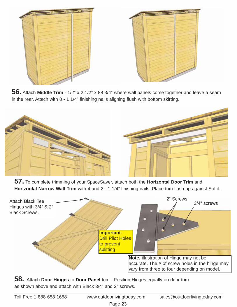
56. Attach Middle Trim - 1/2” x 2 1/2” x 88 3/4” where wall panels come together and leave a seamin the rear. Attach with 8 - 1 1/4” finishing nails aligning flush with bottom skirting.
57. To complete trimming of your SpaceSaver, attach both the Horizontal Door Trim andHorizontal Narrow Wall Trim with 4 and 2 - 1 1/4” finishing nails. Place trim flush up against Soffit.
Attach Black TeeHinges with 3/4” & 2”Black Screws.
Note, illustration of Hinge may not be accurate. The # of screw holes in the hinge mayvary from three to four depending on model.
3/4” screws2“ Screws
58. Attach Door Hinges to Door Panel trim. Position Hinges equally on door trimas shown above and attach with Black 3/4” and 2” screws.
Important- Drill Pilot Holesto prevent splitting
Toll Free 1-888-658-1658 www.outdoorlivingtoday.com [email protected] 23

bottom skirting
60. Position door panel with a 1/2” gap on bottomand evenly spaced on sides and attach hinges toNarrow Trim with 2” black screws. Use extra pieceof siding to help keep the door evenly spaced on bottom. See Step 61 for gap at top. Hint: Do notattach all the 2” screws until both doors are positioned correctly into place. Use Screw Driver totighten screws completely.
Door
1/2” gap atbottom.Evenlyspaced onsides.
Doo
rTrim 2” Black Screws
59. With Hinges attached on to door panel, position in doorway opening. Use Shim Shingles to gap.
61. Make sure Door Panel is aligned evenly attop and edge. When aligned correctly, attach topand middle hinge to narrow trim with hinge hardware provided.
62. Locate and identify all Facia pieces. Front Facia is 4” wide while Rear Facia is 4 1/2” wide.Side Angle Cut Facia is angle cut on both ends. In front corner, align side and front Faciatogether.
Front FaciaSide Angle Cut Facia
Important- Drill Pilot Holesto prevent splitting
Toll Free 1-888-658-1658 www.outdoorlivingtoday.com [email protected] 24
Use ShimShingles togap doorcorrectly.

63. With Side Angle Cut Facia correctly aligned, attach Front Facia to rafter ends with 6 - 1 1/4” finishingnails per piece. Attach Side Angle Cut Facia to batten ends with 4 - 1 1/4” nails. Attach next piece ofFront Facia. Align corner facia as per Step 62. Note, with Angle Cut Facia correctly aligned, a small gapmay occur where they meet. This will be covered by Facia Detail Plate in Step 72.
Toll Free 1-888-658-1658 www.outdoorlivingtoday.com [email protected] 25
Roofing Felt
65. Locate 8” wide x 96” long Roofing Feltand make a 3 3/4” wide fold along the 96”length. Place on top of roof shingles evenlyspaced between outside rafters and securewith 4 - 1 1/4” nails.
66. Nail Roofing Felt down with 1 1/4” nailsto ends of rafters. Roofing Felt will slightlyoverhang rafters.
67. Locate Rear Facia (4 1/2” wide) and align with top edge of roof shingles. Attach facia to rafterends with 6 - 1 1/4” finishing nails per piece. Complete both Rear Facia pieces.
Rear Facia alignedwith top of roof.

69. Place Window Insert into opening. Push so window trim sits flush against wall siding. On theinside, shim Window Insert evenly in cavity. SpaceSaver kits include one additional shingle for shimmingof the window. When properly positioned, secure Window Insert to wall framing cavity with 4 - 2” screws.
70. Attach Interior Door Stops to door framing from inside of shed. Start by securing both Vertical DoorStops. Use Horizontal Door Stop to help determine distance between vertical stops. See Step 71 for detail. Use 4 - 1 1/4” screws to secure each Stop. Stops should overlap door by approx. 1/2”.
Toll Free 1-888-658-1658 www.outdoorlivingtoday.com [email protected] 26
68. Position Roof Ridge Board at the rear of roof to cap off shingles and facia. Ridge Boardshould meet on seam of roof panel. Ridge Board should also completely cover Roofing Felt. Whenaligned correctly, attach with 4 - 1 1/4” nails.
Ridge Boardcapping RearFacia.
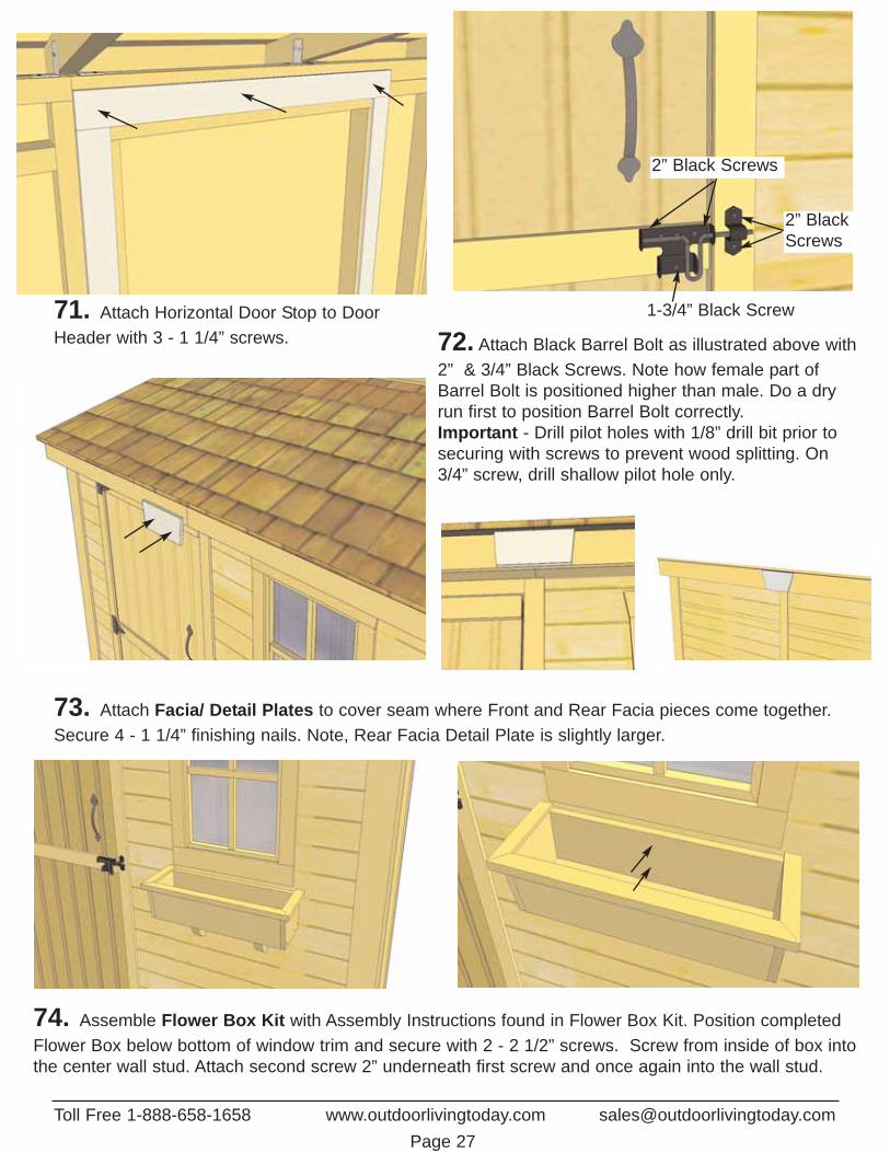
71. Attach Horizontal Door Stop to DoorHeader with 3 - 1 1/4” screws. 72. Attach Black Barrel Bolt as illustrated above with
2” & 3/4” Black Screws. Note how female part ofBarrel Bolt is positioned higher than male. Do a dryrun first to position Barrel Bolt correctly. Important - Drill pilot holes with 1/8” drill bit prior tosecuring with screws to prevent wood splitting. On3/4” screw, drill shallow pilot hole only.
73. Attach Facia/ Detail Plates to cover seam where Front and Rear Facia pieces come together.Secure 4 - 1 1/4” finishing nails. Note, Rear Facia Detail Plate is slightly larger.
Toll Free 1-888-658-1658 www.outdoorlivingtoday.com [email protected] 27
74. Assemble Flower Box Kit with Assembly Instructions found in Flower Box Kit. Position completedFlower Box below bottom of window trim and secure with 2 - 2 1/2” screws. Screw from inside of box intothe center wall stud. Attach second screw 2” underneath first screw and once again into the wall stud.
2” BlackScrews
2” Black Screws
1-3/4” Black Screw

Alternate Door Configuration (Door on 45 1/2” side).
When configuring the SpaceSaverso the Door is positioned on the 45 1/2” side. Follow the general directions in this manual for a regular door configuration on the96” side and note the following differences.
A. Starting in rear corner, position the Narrow Wall Panel bottom framing so it sits flush with plywood. Wall siding will overhang the floor by 1/2”.Note, make sure to use the Larger Floor Panel on the same side as doorway.
NarrowWallPanel
Rear view of SpaceSaverRear SideDoorway
B. Follow sequential Steps 11-15 in the wall section for regular configuration to position and securewall panels.
C. With walls positioned and attached together, locate Door Jamb and orientate on wall stud.
Door Jamb
Toll Free 1-888-658-1658 www.outdoorlivingtoday.com [email protected] 28

D. Align Door Jamb so Flush with bottom of wall framing. Wall siding will overhang 1/2” on outside. Jamb will overhang floor by 1/2”. When correctly aligned, attach Door Jamb to wall stud with4 - 2 1/2” screws.
E. Position and attach the Door Header to DoorJamb and Narrow Wall Panel top framing.Header should sit flush with Door Jamb andOutside of Narrow Wall Panel Siding. Attachwith 3 - 2 1/2” screws.
Doorway
F. Align and secure Optional Door Trim.(1/2” x 2 1/2” x88 3/4”). Position on left side flush with outside narrowwall stud. Trim should also be aligned flush with bottomskirting. Attach with 8 - 1 1/4” finishing nails. See H. foralternative method. See Step 51 to finish Door Trim.
OptionalDoor Trim
G. Attach 1 Vertical and Horizontal Door Stop.See Step 69 for detail.
OptionalDoorTrim cut80” long
Unused VerticalDoor Stop (2 1/2”wide) cut to 32”and 8” long forHorizontal DoorTrim
DoorStops
H. Alternatively, you may trim door out usingunused Vertical Door Stop. Cut to 8” and 32”lengths. Cut the Optional Door Trim down to80” and attach as per Step 57.
Doo
rJam
b
siding overhanging1/2”
Toll Free 1-888-658-1658 www.outdoorlivingtoday.com [email protected] 29

We hope your experience constructing our building has been both positive and rewarding.
We value your feedback and would like to hear back from you on how well we are doing in the following areas:
1. Customer Service2. On Time Shipping3. Motor Freight Delivery4. Quality of Materials5. Assembly Manual6. Overall Satisfaction.
Please call, write or email us at: Outdoor Living Today PartnershipP.O. Box 96Sumas, Washington98295
Toll Line: 1.888.658.1658 | Fax: 1.604.462.5333 | [email protected] 30
The materials contained in this Assembly Manual maybe downloaded or copied provided that ALL copiesretain the copyright and any other proprietary noticescontained on the materials. No material may be modified, edited or taken out of context such that itsuse creates a false or misleading statement or impression as to the positions, statements or actions.
Completed 8x4 SpaceSaver Shed
Note; Our Sheds are shippedas an unfinished product. Ifexposed to the elements, thewestern red cedar lumber willweather to a silvery-gray color.If you prefer to keep the cedarlumber looking closer to theoriginal color, we suggest thatyou treat the wood with a goodoil base wood stain. You mayalso wish to paint your newshed rather than stain it. Inboth cases we recommendthat you consult with a paintand stain dealer in your areafor their recommendations.