896 Manual for Windows - MOTUcdn-data.motu.com/manuals/firewire-usb-audio/896_Manual_Win.pdf ·...
58
™ 1280 Massachusetts Avenue Cambridge, MA 02138 Business voice: (617) 576-2760 Business fax: (617) 576-3609 Tech support phone: (617) 576-3066 Tech support fax: (617) 354-3068 Tech support email: [email protected] Web site: www.motu.com MOTU 896 User’s Guide for Windows
Transcript of 896 Manual for Windows - MOTUcdn-data.motu.com/manuals/firewire-usb-audio/896_Manual_Win.pdf ·...

™
1280 Massachusetts AvenueCambridge, MA 02138Business voice: (617) 576-2760Business fax: (617) 576-3609Tech support phone: (617) 576-3066Tech support fax: (617) 354-3068Tech support email: [email protected] site: www.motu.com
MOTU 896
User’s Guide for Windows
!896 Manual/Win Page 1 Tuesday, November 27, 2001 5:02 PM

SAFETY PRECAUTIONS AND ELECTRICAL REQUIREMENTS
WARNING: TO REDUCE THE RISK OF FIRE OR ELECTRICAL SHOCK, DO NOT EXPOSE THIS APPLIANCE TO RAIN OR OTHER MOISTURE.
CAUTION: TO REDUCE THE RISK OF ELECTRICAL SHOCK, DO NOT REMOVE COVER. NO USER-SERVICEABLE PARTS INSIDE. REFER SERVICING TO QUALIFIED SERVICE PERSONNEL.
WARNING: DO NOT PERMIT FINGERS TO TOUCH THE TERMINALS OF PLUGS WHEN INSTALLING OR REMOVING THE PLUG TO OR FROM THE OUTLET.
WARNING: IF NOT PROPERLY GROUNDED THE MOTU 896 COULD CAUSE AN ELECTRICAL SHOCK.
The MOTU 896 is equipped with a three-conductor cord and grounding type plug which has a grounding prong, approved by Underwriters' Laboratories and the Canadian Standards Association. This plug requires a mating three-conductor grounded type outlet as shown in Figure A below.
If the outlet you are planning to use for the MOTU 896 is of the two prong type, DO NOT REMOVE OR ALTER THE GROUNDING PRONG IN ANY MANNER. Use an adapter as shown below and always connect the grounding lug to a known ground. It is recommended that you have a qualified electrician replace the TWO prong outlet with a properly grounded THREE prong outlet. An adapter as illustrated below in Figure B is available for connecting plugs to two-prong receptacles.
WARNING: THE GREEN GROUNDING LUG EXTENDING FROM THE ADAPTER MUST BE CONNECTED TO A PERMANENT GROUND SUCH AS TO A PROPERLY GROUNDED OUTLET BOX. NOT ALL OUTLET BOXES ARE PROPERLY GROUNDED.
If you are not sure that your outlet box is properly grounded, have it checked by a qualified electrician. NOTE: The adapter illustrated is for use only if you already have a properly grounded two-prong receptacle. Adapter is not allowed in Canada by the Canadian Electrical Code. Use only three wire extension cords which have three-prong grounding type plugs and three-prong receptacles which will accept the MOTU 896 plug.
IMPORTANT SAFEGUARDS
1. Read instructions - All the safety and operating instructions should be read before operating the MOTU 896.2. Retain instructions - The safety instructions and owner's manual should be retained for future reference.3. Heed Warnings - All warnings on the MOTU 896 and in the owner's manual should be adhered to.4. Follow Instructions - All operating and use instructions should be followed.5. Cleaning - Unplug the MOTU 896 from the computer before cleaning and use a damp cloth. Do not use liquid or aerosol cleaners.6. Overloading - Do not overload wall outlets and extension cords as this can result in a risk of fire or electrical shock.7. Power Sources - This MOTU 896 should be operated only from the type of power source indicated on the marking label. If you are not sure of the type of power supply to your location, consult your local power company. 8. Power-Cord Protection - Power-supply cords should be routed so that they are not likely to be walked on or pinched by items placed upon or against them. Pay particular attention to cords and plugs, convenience receptacles, and
the point where they exit from the MOTU 896.9. Lightning - For added protection for the MOTU 896 during a lightning storm, unplug it from the wall outlet. This will prevent damage to the MOTU 896 due to lightning and power line surges.10. Servicing - Do not attempt to service this MOTU 896 yourself as opening or removing covers will expose you to dangerous voltage and other hazards. Refer all servicing to qualified service personnel.11. Damage Requiring Service - Unplug the MOTU 896 from the computer and refer servicing to qualified service personnel under the following conditions.
a. When the power supply cord or plug is damaged.b. If liquid has been spilled or objects have fallen into the MOTU 896.c. If the MOTU 896 has been exposed to rain or water.d. If the MOTU 896 does not operate normally by following the operating instructions in the owner's manual.e. If the MOTU 896 has been dropped or the cabinet has been damaged.f. When the MOTU 896 exhibits a distinct change in performance, this indicates a need for service.
12. Replacement Parts - When replacement parts are required, be sure the service technician has used replacement parts specified by the manufacturer or have the same characteristics as the original part. Unauthorized substitutions may result in fire, electric shock or other hazards.
13. Safety Check - Upon completion of any service or repairs to this MOTU 896, ask the service technician to perform safety checks to determine that the product is in safe operating conditions.
ENVIRONMENT
Operating Temperature: 10°C to 40°C (50°F to 104°)
AVOID THE HAZARDS OF ELECTRICAL SHOCK AND FIRE
Do not handle the power cord with wet hands. Do not pull on the power cord when disconnecting it from an AC wall outlet. Grasp it by the plug.
INPUT
Line Voltage: 100 - 120 volts AC, RMS (US and Japan) or 220 - 250 volts AC, RMS (Europe). Frequency: 47 - 63 Hz single phase. Power: 7 watts maximum.
CAUTION: DANGER OF EXPLOSION IF BATTERY IS REPLACED. REPLACE ONLY WITH THE SAME OR EQUIVALENT TYPE RECOMMENDED BYMANUFAC-TURER. DISPOSE OF USED BATTERY ACCORDING TO MANUFACTURER’S INSTRUCTIONS.
3-prong plug
Grounding prong
Properly grounded 3-prong outlet
Grounding lug
Screw
3-prong plug
Adapter
Make sure this is connected to a known ground.
Two-prong receptacle
Figure A Figure B
!896 Manual/Win Page 2 Tuesday, November 27, 2001 5:02 PM

CHAPTER
3
Contents
5
Quick Reference: MOTU 896 Front Panel
6
Quick Reference: MOTU 896 Rear Panel
7
Quick Reference: MOTU FireWire Audio Console
9
About the MOTU 896
13
Packing List and Windows System Requirements
15
IMPORTANT! Run the MOTU 896 Software Installer First
17
Installing the MOTU 896 Hardware
35
MOTU FireWire Audio Console
43
ASIO-compatible Audio Software
49
Windows Multimedia-compatible Audio Software
53
Performance Tips & Troubleshooting
!896 Manual/Win Page 3 Tuesday, November 27, 2001 5:02 PM

About the Mark of the Unicorn License Agreement and Limited Warranty on Software
TO PERSONS WHO PURCHASE OR USE THIS PRODUCT: carefully read all the terms and conditions of the “click-wrap” license agreement presented to you when you install the software. Using the software or this documentation indicates your acceptance of the terms and conditions of that license agreement.
Mark of the Unicorn, Inc. (“MOTU”) owns both this program and its documentation. Both the program and the documentation are protected under applicable copyright, trademark, and trade-secret laws. Your right to use the program and the documentation are limited to the terms and conditions described in the license agreement.
Reminder of the terms of your license
This summary is not your license agreement, just a reminder of its terms. The actual license can be read and printed by running the installation program for the software. That license agreement is a contract, and clicking “Accept” binds you and MOTU to all its terms and conditions. In the event anything contained in this summary is incomplete or in conflict with the actual click-wrap license agreement, the terms of the click-wrap agreement prevail.
YOU MAY: (a) use the enclosed program on a single computer; (b) physically transfer the program from one computer to another provided that the program is used on only one computer at a time and that you remove any copies of the program from the computer from which the program is being transferred; (c) make copies of the program solely for backup purposes. You must reproduce and include the copyright notice on a label on any backup copy.
YOU MAY NOT: (a) distribute copies of the program or the documentation to others; (b) rent, lease or grant sublicenses or other rights to the program; (c) provide use of the program in a computer service business, network, time-sharing, multiple CPU or multiple user arrangement without the prior written consent of MOTU; (d) translate, adapt, reverse engineer, decompile, disassemble, or otherwise alter the program or related documentation without the prior written consent of MOTU.
MOTU warrants to the original licensee that the disk(s) on which the program is recorded be free from defects in materials and workmanship under normal use for a period of ninety (90) days from the date of purchase as evidenced by a copy of your receipt. If failure of the disk has resulted from accident, abuse or misappli-cation of the product, then MOTU shall have no responsibility to replace the disk(s) under this Limited Warranty.
THIS LIMITED WARRANTY AND RIGHT OF REPLACEMENT IS IN LIEU OF, AND YOU HEREBY WAIVE, ANY AND ALL OTHER WARRANTIES, BOTH EXPRESS AND IMPLIED, INCLUDING BUT NOT LIMITED TO WARRANTIES OF MERCHANTABILITY AND FITNESS FOR A PARTICULAR PURPOSE. THE LIABILITY OF MOTU PURSUANT TO THIS LIMITED WARRANTY SHALL BE LIMITED TO THE REPLACEMENT OF THE DEFECTIVE DISK(S), AND IN NO EVENT SHALL MOTU OR ITS SUPPLIERS, LICENSORS, OR AFFILIATES BE LIABLE FOR INCIDENTAL OR CONSEQUENTIAL DAMAGES, INCLUDING BUT NOT LIMITED TO LOSS OF USE, LOSS OF PROFITS, LOSS OF DATA OR DATA BEING RENDERED INACCURATE, OR LOSSES SUSTAINED BY THIRD PARTIES EVEN IF MOTU HAS BEEN ADVISED OF THE POSSIBILITY OF SUCH DAMAGES. THIS WARRANTY GIVES YOU SPECIFIC LEGAL RIGHTS WHICH MAY VARY FROM STATE TO STATE. SOME STATES DO NOT ALLOW THE LIMITATION OR EXCLUSION OF LIABILITY FOR CONSEQUENTIAL DAMAGES, SO THE ABOVE LIMITATION MAY NOT APPLY TO YOU.
Update Policy
In order to be eligible to obtain updates of the program, you must complete and return the attached Mark of the Unicorn Purchaser Registration Card to MOTU.
Copyright Notice
Copyright © 2001 by Mark of the Unicorn, Inc. All rights reserved. No part of this publication may be reproduced, transmitted, transcribed, stored in a retrieval system, or translated into any human or computer language, in any form or by any means whatsoever, without express written permission of Mark of the Unicorn, Inc., 1280 Massachusetts Avenue, Cambridge, MA, 02138, U.S.A.
Limited Warranty on Hardware
Mark of the Unicorn, Inc. and S&S Research (“MOTU/S&S”) warrant this equipment against defects in materials and workmanship for a period of NINETY (90) DAYS from the date of original retail purchase. This warranty applies only to hardware products; MOTU software is licensed and warranted pursuant to separate written statements.
If you discover a defect, first write or call Mark of the Unicorn at (617) 576-2760 to obtain a Return Merchandise Authorization Number. No service will be performed on any product returned without prior authorization. MOTU will, at its option, repair or replace the product at no charge to you, provided you return it during the warranty period, with transportation charges prepaid, to Mark of the Unicorn, Inc., 1280 Massachusetts Avenue, MA 02138. You must use the product’s original packing material for in shipment, and insure the shipment for the value of the product. Please include your name, address, telephone number, a description of the problem, and the original, dated bill of sale with the returned unit and print the Return Merchandise Authorization Number on the outside of the box below the shipping address.
This warranty does not apply if the equipment has been damaged by accident, abuse, misuse, or misapplication; has been modified without the written permission of MOTU, or if the product serial number has been removed or defaced.
ALL IMPLIED WARRANTIES, INCLUDING IMPLIED WARRANTIES OF MERCHANTABILITY AND FITNESS FOR A PARTICULAR PURPOSE, ARE LIMITED IN DURATION TO NINETY (90) DAYS FROM THE DATE OF THE ORIGINAL RETAIL PURCHASE OF THIS PRODUCT.
THE WARRANTY AND REMEDIES SET FORTH ABOVE ARE EXCLUSIVE AND IN LIEU OF ALL OTHERS, ORAL OR WRITTEN, EXPRESS OR IMPLIED. No MOTU/S&S dealer, agent, or employee is authorized to make any modification, extension, or addition to this warranty.
MOTU/S&S ARE NOT RESPONSIBLE FOR SPECIAL, INCIDENTAL, OR CONSEQUENTIAL DAMAGES RESULTING FROM ANY BREACH OF WARRANTY, OR UNDER ANY LEGAL THEORY, INCLUDING LOST PROFITS, DOWNTIME, GOODWILL, DAMAGE OR REPLACEMENT OF EQUIPMENT AND PROPERTY AND COST OF RECOVERING REPROGRAMMING, OR REPRODUCING ANY PROGRAM OR DATA STORED IN OR USED WITH MOTU/S&S PRODUCTS.
Some states do not allow the exclusion or limitation of implied warranties or liability for incidental or consequential damages, so the above limitation or exclusion may not apply to you. This warranty gives you specific legal rights, and you may have other rights which vary from state to state.
MOTU, AudioDesk, MOTU, Mark of the Unicorn and the unicorn silhouette logo are trademarks of Mark of the Unicorn, Inc.
This equipment has been type tested and found to comply with the limits for a class B digital device, pursuant to Part 15 of the FCC Rules. These limits are designed to provide reasonable protection against harmful interference in a residential installation. This equipment generates, uses, and can radiate radio frequency energy and, if not installed and used in accordance with the instruction manual, may cause harmful interference to radio communications. However, there is no guarantee that interference will not occur in a particular installation. If this equipment does cause interference to radio or television equipment reception, which can be determined by turning the equipment off and on, the user is encouraged to try to correct the interference by any combination of the following measures:
• Relocate or reorient the receiving antenna
• Increase the separation between the equipment and the receiver
• Plug the equipment into an outlet on a circuit different from that to which the receiver is connected
If necessary, you can consult a dealer or experienced radio/television technician for additional assistance.
PLEASE NOTE: only equipment certified to comply with Class B (computer input/output devices, terminals, printers, etc.) should be attached to this equipment, and it must have shielded interface cables in order to comply with the Class B FCC limits on RF emissions.
WARNING: changes or modifications to this unit not expressly approved by the party responsible for compliance could void the user's authority to operate the equipment.
!896 Manual/Win Page 0 Tuesday, November 27, 2001 5:02 PM

0
Qu
ick
Ref
eren
ce: M
OTU
89
6 F
ron
t Pan
el
This
is a s
tand
ard
quar
ter-i
nch s
tere
o he
adph
one j
ack.
Its
outp
ut m
atch
es th
e m
ain
outs
on
the
rear
pan
el.
The M
OTU
896
lets
you
mon
itor a
ny an
alog
or A
ES/
EBU
inpu
t (or
inpu
t pai
r) via
th
e mai
n ou
ts (a
nd th
e he
adph
one o
ut). T
his k
nob
cont
rols
the l
evel
of t
his
mon
itore
d sig
nal. T
his
feat
ure i
s cal
led
CueM
ix Pl
us™
.
This
togg
le sw
itch
prov
ides
phan
tom
pow
er
for a
cond
ense
r mic
plug
ged
into
this
inpu
t. Up
is o
n.
Thes
e 10-
segm
ent l
evel
met
ers a
re d
edica
ted
sole
ly to
the 8
96’s e
ight
anal
og in
puts.
The t
op re
d ‘ov
er’ L
ED lig
hts u
p w
hen
the s
igna
l rea
ches
full
scal
e—fo
r eve
n ju
st o
ne sa
mpl
e—an
d re
mai
ns
illum
inat
ed u
ntil y
ou cl
ear i
t in
the s
oftw
are.
The
seco
nd ‘o
ver’ L
ED b
elow
onl
y lig
hts u
p m
omen
-ta
rily s
o tha
t you
can c
ontin
ue to
adju
st le
vel e
ven
afte
r clip
ping
has
just
occ
urre
d.
Thes
e lig
hts i
ndica
te th
e glo
bal s
ampl
e rat
e at w
hich
the
MOT
U 89
6 is
oper
atin
g. Us
e the
MOT
U Fir
eWire
Aud
io
Cons
ole t
o set
the s
ampl
e rat
e or t
o cho
ose a
n ext
erna
l clo
ck
sour
ce, fr
om w
hich
the s
ampl
e rat
e will
be d
erive
d. W
hen
no sa
mpl
e clo
ck is
curre
ntly
pres
ent, t
hese
light
s flas
h. Fo
r ex
ampl
e, if
you’
ve se
t the
MOT
U 89
6 to
slav
e to
an ex
tern
al
clock
, suc
h as
ADA
T, bu
t the
re is
no
clock
sign
al cu
rrent
ly be
ing
dete
cted
, the
se lig
hts w
ill fl
ash.
FireW
ire is
a “p
lug-
and-
play
” pr
otoc
ol. T
hat m
eans
that
you
can
turn
off
the M
OTU
896
and
turn
it b
ack o
n (o
r eve
n un
plug
it) w
ithou
t res
tarti
ng
your
com
pute
r. Kee
p in
min
d, ho
wev
er, t
hat i
f you
wish
to
chan
ge th
e MOT
U 89
6’s
setti
ngs i
n th
e MOT
U Fir
eWire
Au
dio
Cons
ole,
the M
OTU
896
need
s to
be p
lugg
ed in
and
switc
hed
on.
Thes
e eig
ht tr
im kn
obs p
rovid
e gai
n ad
just
men
t with
in a
rang
e of a
bout
40d
B fo
r ea
ch an
alog
inpu
t (w
hen
the 3
-way
switc
h on
the r
ear p
anel
is se
t to
eith
er M
IC o
r LI
NE. If
the 3
-way
switc
h is
set t
o +
4/FI
XED,
the c
orre
spon
ding
fron
t-pan
el tr
im p
ots
is by
pass
ed). B
ecau
se ea
ch in
put a
lso h
as a
micr
opho
ne p
ream
p, yo
u ca
n pl
ug ju
st
abou
t any
thin
g in
to th
em: a
micr
opho
ne, a
gui
tar, a
synt
h —
you
nam
e it.
For a
micr
opho
ne or
una
mpl
ified
inst
rum
ent p
ickup
, set
the r
ear-p
anel
3-w
ay sw
itch
to M
IC, p
lug
in yo
ur m
ic (X
LR o
r qua
rter-i
nch
plug
) flip
on
48V
phan
tom
pow
er (i
f ne
cess
ary)
and
use t
he tr
im kn
ob as
nee
ded
to ad
just
the l
evel
.
For -
10dB
(unb
alan
ced)
inpu
ts (l
ike sy
nths
) or +
4 (b
alan
ced)
sign
als,
set t
he re
ar
pane
l 3-w
ay sw
itch
to LI
NE an
d us
e the
trim
knob
to ad
just
the l
evel
. You
can
use
eith
er an
XLR
or q
uarte
r-inc
h pl
ug. (N
ote:
the c
ompl
ete t
rim ra
nge,
from
all t
he w
ay
dow
n w
ith th
e MIC
setti
ng to
all t
he w
ay u
p w
ith th
e LIN
E set
ting
is ar
ound
55d
B to
tal. T
he M
IC se
tting
pro
vides
a 40
dB ra
nge (
appr
oxim
atel
y -37
dBu
to +
5dBu
) and
th
e LIN
E set
ting
offe
rs a 3
0dB
rang
e (ap
prox
imat
ely -
16dB
u to
+15
dBu)
with
som
e ov
erla
p be
twee
n th
em.)
If yo
u ha
ve +
4 in
puts
for w
hich
you’d
like t
o m
aint
ain
unity
gai
n (fo
r lev
els u
p to
+
18dB
u), s
et th
e rea
r-pan
el 3
-way
switc
h to
+4/
FIXE
D. Yo
u ca
n us
e eith
er an
XLR
or
quar
ter-i
nch
plug
.
This
foot
ped
al in
put i
s for
M
acin
tosh
ope
ratio
n on
ly.
The v
olum
e kno
b co
ntro
ls th
e hea
dpho
ne o
ut an
d, if
the t
oggl
e sw
itch i
s up,
the
mai
n ou
ts, to
o. If
the
togg
le sw
itch
is do
wn,
the
volu
me k
nob
only
affe
cts
the h
eadp
hone
out
.
This
bank
of le
vel m
eter
s can
be pr
ogra
mm
ed to
di
splay
one
of t
hree
diff
eren
t ban
ks: a
nalo
g ou
tput
, ADA
T opt
ical in
put, o
r ADA
T opt
ical
outp
ut. U
se th
e MOT
U Fir
eWire
Aud
io Co
nsol
e to
choo
se w
hich
bank
you’d
like t
o vie
w w
ith th
ese
met
ers. T
he LE
Ds to
the l
eft s
how
whi
ch b
ank
you
are c
urre
ntly
mon
itorin
g.
The l
ight
that
is ill
umin
ated
her
e tel
ls yo
u w
hich
ban
k (an
alog
in, A
DAT i
n, o
r AD
AT o
ut) y
ou ar
e mon
itorin
g w
ith th
e pr
ogra
mm
able
met
er b
ank t
o th
e rig
ht.
Thes
e met
ers
disp
lay th
e lev
el fo
r th
e 896
’s m
ain
outs
.
Thes
e met
ers c
an b
e pro
gram
med
to d
isplay
eith
er
AES/
EBU
inpu
t or o
utpu
t. Use
the M
OTU
FireW
ire
Audi
o Co
nsol
e to
choo
se. T
he LE
Ds to
the r
ight
in
dica
te w
hat y
ou ar
e cur
rent
ly m
onito
ring.
!896 Manual/Win Page 5 Tuesday, November 27, 2001 5:02 PM

Thes
e AES
/EBU
conn
ecto
rs ca
n ha
ndle
any s
uppo
rted
sam
ple r
ate (
44.1
, 48,
88.2
or
96),
and
they
are a
lso
equi
pped
with
a sa
mpl
e rat
e co
nver
ter s
o yo
u ca
n in
put o
r ou
tput
at a
diffe
rent
rate
than
th
e 896
. For
det
ails,
see
“Syn
cing A
ES/E
BU de
vices
” on
page
28.
0
Qu
ick
Ref
eren
ce: M
OTU
89
6 R
ear
Pan
el
Conn
ect t
he M
OTU
896 t
o th
e com
pute
r her
e usin
g th
e sta
ndar
d 13
94
FireW
ire ca
ble p
rovid
ed
with
your
MOT
U 89
6.
Thes
e tw
o XL
R ja
cks s
erve
as th
e MOT
U 89
6’s m
ain
anal
og o
utpu
ts. Yo
u ca
n co
nnec
t the
m to
a se
t of p
ower
ed st
udio
m
onito
rs an
d th
en co
ntro
l the
volu
me
from
the f
ront
pan
el “V
olum
e” kn
ob.
The s
igna
l tha
t com
es o
ut o
f the
se
outp
uts i
s a m
ix of
anal
og ou
tput
s 1 an
d 2
and a
ny liv
e Cue
Mix™
Plus
inpu
t tha
t you
ha
ve ch
osen
to m
onito
r fro
m a
MOT
U 89
6 in
put (
or in
put p
air).
To h
ear d
isk tr
acks
in
your
audi
o so
ftwar
e on
thes
e mai
n ou
ts,
assig
n th
e disk
trac
ks (a
nd m
aste
r fad
er)
to A
nalo
g Ou
ts 1
-2.
Thes
e eig
ht an
alog
inpu
ts ar
e Neu
trik™
com
bo co
nnec
tors
that
acce
pt ei
ther
an X
LR p
lug
or a
quar
ter-i
nch
plug
. The
y hav
e 24-
bit, 6
4x ov
ersa
mpl
ing
conv
erte
rs. Ea
ch in
put i
s equ
ippe
d w
ith a
3-w
ay in
put l
evel
switc
h w
ith th
ree s
ettin
gs:
LINE
: Use
this
setti
ng fo
r +4d
B or
-10d
B in
puts,
such
as sy
nthe
sizer
s or c
onsu
mer
audi
o eq
uipm
ent.
Adju
st th
e inp
ut le
vel a
s nee
ded
with
the c
orre
spon
ding
fron
t pan
el Tr
im co
ntro
l and
leve
l met
er fo
r th
is in
put. T
his s
ettin
g of
fers
a trim
rang
e of a
roun
d 30
dB (a
ppro
ximat
ely -
16dB
u to
+15
dBu)
.
+4 /
FIXE
D: U
se th
is se
tting
for +
4 bal
ance
d in
puts
for w
hich
you
do n
ot w
ish to
mod
ify th
e gai
n. Th
is po
sitio
n di
seng
ages
the f
ront
pan
el tr
im kn
ob. T
his s
ettin
g al
so p
rovid
es sl
ight
ly m
ore a
ttenu
atio
n th
an th
e LIN
E set
ting,
allo
win
g le
vels
up to
+18
dBu.
MIC
: Thi
s set
ting
feed
s the
inpu
t sig
nal (
XLR
or q
uarte
r-inc
h) to
the b
uilt-
in p
ream
p fo
r add
ition
al
gain
. Use
it fo
r any
micr
opho
ne o
r una
mpl
ified
inst
rum
ent p
ickup
. Eng
age p
hant
om p
ower
for
cond
ense
r mics
with
the f
ront
-pan
el 4
8V sw
itch
(up
is on
). Use
the c
orre
spon
ding
fron
t-pan
el tr
im
knob
and
leve
l met
er to
adju
st th
e inp
ut le
vel a
s nee
ded.
This
setti
ng o
ffers
a trim
rang
e of a
roun
d 40
dB (a
ppro
ximat
ely -
37dB
u to
+5d
Bu).
Anal
og o
utpu
ts 1
and
2 ar
e dup
licat
ed o
n th
e MOT
U 89
6’s m
ain
outp
uts (
to th
e lef
t), as
wel
l as t
he fr
ont
pane
l ste
reo h
eadp
hone
jack
. How
ever
, thes
e out
puts
do
not
inclu
de an
y live
CueM
ix™ P
lus a
udio.
The M
OTU
896’s
eigh
t ana
log o
utpu
ts ar
e XLR
conn
ecto
rs w
ith
+4
/ -10
switc
habl
e out
put (
600
Ohm
impe
danc
e). T
hey a
re
equi
pped
with
24-
bit, 1
28x o
versa
mpl
ing
enha
nced
mul
tibit
A/D
conv
erte
rs ca
pabl
e of 4
4.1,
48, 8
8.2 a
nd 96
kHz r
ecor
ding
.
Thes
e ADA
T opt
ical
digi
tal I
/O co
nnec
tors
can
be co
nnec
ted
eith
er to
an A
DAT o
r an
y ADA
T-co
mpa
tible
“li
ghtp
ipe”
dev
ice
(suc
h as
a di
gita
l m
ixer).
ADA
T opt
ical
supp
lies e
ight
chan
nels
of 2
4-bi
t dig
ital I
/O at
If yo
u are
usin
g the
MOT
U 89
6 with
an A
DAT, u
se th
is st
anda
rd A
DAT S
YNC I
NPUT
to co
nnec
t the
MOT
U 89
6 to t
he en
d of y
our A
DAT s
ync
chai
n. Fo
r exa
mpl
e, if
you
have
thre
e ADA
Ts, c
hain
the A
DATs
in th
e usu
al fa
shio
n (S
YNC O
UT to
SYNC
IN, e
tc.),
and
then
conn
ect t
he
last
ADA
T’s SY
NC O
UT to
this
SYNC
IN. T
his c
onne
ctio
n al
low
s you
to m
ake s
ampl
e-ac
cura
te au
dio
trans
fers
betw
een
Audi
oDes
k (or
ot
her s
ampl
e-ac
cura
te so
ftwar
e) an
d th
e ADA
Ts. If
you
have
a M
OTU
MID
I Tim
epie
ce AV
or D
igita
l Tim
epie
ce, m
ake i
t the
mas
ter o
f the
AD
AT SY
NC ch
ain
so th
at yo
u ca
n co
ntro
l eve
ryth
ing
from
Aud
ioDe
sk (o
r you
r oth
er M
IDI M
achi
ne Co
ntro
l com
patib
le so
ftwar
e).
The 8
96 p
ower
supp
ly is
switc
habl
e bet
wee
n 115
V and
24
0V o
pera
tion.
It sh
ould
al
read
y be s
et to
the p
rope
r vo
ltage
for y
our c
ount
ry, b
ut
you
can
chec
k the
setti
ng an
d ad
just
it if
nec
essa
ry w
ith th
e re
d sw
itch
just
to th
e lef
t of
this
pow
er co
rd re
cept
acle
(on
the s
ide o
f the
met
al ch
assis
).
Use t
he w
ord c
lock
inpu
t an
d ou
tput
for d
igita
l tra
nsfe
rs w
ith d
evice
s th
at ca
nnot
slav
e to
the
clock
supp
lied
by th
eir
digi
tal I
/O co
nnec
tion
with
the 8
96.
Daisy
-cha
in u
p to
four
896
’s to
a sin
gle F
ireW
ire b
us. Y
ou ca
n al
so
conn
ect a
MOT
U 82
8, Gl
yph
M P
roje
ct Fi
reW
ire h
ard
drive
or
othe
r Fire
Wire
dev
ice. F
or d
etai
ls,
see “
Conn
ectin
g m
ultip
le M
OTU
896
inte
rface
s” on
pag
e 33.
!896 Manual/Win Page 6 Tuesday, November 27, 2001 5:02 PM

CHAPTER
7
0
Quick Reference: MOTU FireWire Audio Console
Audio System Setup in Cubase VST
Determines the master clock source for your entire MOTU 896 system. If you’re just using the analog ins and outs, set this to ‘Internal’. The other settings are for digital transfers via AES/EBU or external synchronization via the ADAT SYNC in or Word Clock port. If you have multiple MOTU FireWire interfaces, you’ll see all eligible clock sources from all available interfaces.
The MOTU FireWire Audio Console gives you complete control over the settings in your MOTU 896 hard disk recording system. There are several ways to access these settings. But the settings are the same, regardless of how you access them.
� From the Windows Start menu, choose Programs>MOTU>MOTU FireWire Audio Console.
� From within Cubase™, go to the Audio System Setup window and click on the ASIO Control Panel button.
� From within other applications, refer to their documentation.
How to access these settings
Choosing a smaller setting here reduces the delay you may hear when listening to live input that you are running through effects plug-ins in your software. But lower settings also increase the strain on your computer. For details, see “Samples Per Buffer” on page 38.
Choose the global sample rate for the system here.
This is the MOTU 896’s no-latency CueMix™ Plus monitoring feature. The inputs you choose here will be mixed with the main outs and can be controlled with the ‘Monitor Level’ knob on the front panel.
Check this option if the audio software you are using with the MOTU 896 does not support Windows WDM drivers and instead only supports legacy MME (Wave) drivers. When checked, this option makes all of the MOTU 896 inputs and outputs available to legacy Wave-driver compatible audio software.
Use these tabs to access general settings and settings that are specific to the MOTU 896 interface. If you have multiple MOTU FireWire audio interfaces connected, each gets its own tab.
If you have a foot switch connected to the MOTU 896, these settings let you map the foot switch to any computer keyboard key for both the up and down position.
Choose the desired optical format you’d like to use for the optical input and output. For the 896, the choices are ‘ADAT’ or ‘OFF’. Turning them off frees up FireWire bandwidth for other devices.
This menu provides several options for the MOTU 896’s AES/EBU sample rate conversion. For further details see, “Syncing AES/EBU devices” on page 28.Lets you choose what to monitor with the 896’s
programmable front panel meters.
The Clip Hold Time controls how long the top-most red LED remains illuminated after clipping. The Peak Hold Time controls how long the highest illuminated LED remains lit before going dark.
Use the ‘Disable’ check box to take the interface off-line without shutting off its power. Doing so frees up FireWire bandwidth. If you are running a MOTU 896 interface at a high sample rate (96
or 88.2), this option appears at the bottom of the interface settings. It lets you choose a word clock output rate that either matches the global sample rate (e.g. 96 kHz) or halves the global rate (e.g. 48 kHz instead of 96 kHz).
This option should always be left on (checked). There are only a few rare cases in which you would want to turn it off. For details, refer to the MOTU tech support database at www.motu.com.
!896 Manual/Win Page 7 Tuesday, November 27, 2001 5:02 PM

8
!896 Manual/Win Page 8 Tuesday, November 27, 2001 5:02 PM

CHAPTER
9
1
About the MOTU 896
OVERVIEW
The MOTU 896 is a computer-based hard disk
recording system for Mac OS and Windows that
offers 18 simultaneous inputs and outputs. The
MOTU 896 consists of a standard 19-inch,
double-space, rack-mountable I/O unit that
connects directly to a computer via a standard
IEEE 1394 FireWire™ cable. The MOTU 896 offers
the following:
�
Operation at 44.1, 48, 88.2 or 96 kHz
�
Eight 24-bit analog outputs individually
switchable between +4 and -10dB operation
�
Eight 24-bit analog inputs equipped with
Neutrik “combo” jacks and independent 3-way
level switch for MIC, LINE or +4/FIXED inputs
�
Eight-channel ADAT optical digital I/O
�
AES/EBU with sample rate conversion
�
Two extra analog main outs
�
Eight mic preamps (one on each input)
�
Independent 48V phantom power for each input
�
Independent front-panel trim for each input
�
Sample-accurate ADAT sync input
�
Word clock input and output
�
Two FireWire jacks for chaining multiple units
�
Foot switch input for hands-free punch-in/out
�
Front-panel Headphone jack
�
Main volume knob (for headphone + main outs)
�
CueMix™ Plus no-latency monitoring
�
10-segment LED level meters for each input
�
10-segment programmable LEDs for analog
output, ADAT input or ADAT output
�
10-segment programmable LEDs for AES/EBU
input or output
�
Switchable power supply (110V or 220V)
With a variety of I/O formats, mic preamps,
no-latency monitoring of live input and synchroni-
zation capabilities, the MOTU 896 is a complete,
portable “studio in a box” when used with a
Macintosh or Windows computer. A WDM driver
is included for audio applications running under
Windows Me/2K/XP. Also included is an ASIO
driver for multi-channel operation with any
Windows audio software that supports ASIO
drivers.
THE MOTU 896 I/O REAR PANEL
The MOTU 896 rear panel has the following
connectors:
�
Eight 24-bit XLR analog outputs, each equipped
with an independent 2-way output level switch (+4
or -10dB)
�
Eight 24-bit Neutrik “combo” (XLR + balanced
quarter-inch) analog inputs, each equipped with
an independent 3-way level switch (MIC, LINE,
+4/FIXED), mic preamp, front-panel 48V
phantom power switch, and front-panel trim knob
�
One set of ADAT optical ‘light pipe’ connectors
(8 channels of ADAT optical input and output)
�
AES/EBU input and output
�
Two XLR main analog outputs with volume
knob (on the front panel)
�
One 9-pin ADAT SYNC IN connector
!896 Manual/Win Page 9 Tuesday, November 27, 2001 5:02 PM

A B O U T T H E M O T U 8 9 6
10
�
BNC word clock input and output
�
Two 1394 FireWire jacks
18 simultaneous inputs and outputs
All MOTU 896 inputs and outputs can be used
simultaneously, for a total of 18 inputs and outputs
(8 analog + 8 ADAT optical + 2 AES/EBU).
Analog
The analog inputs are equipped with 24-bit, 64x
oversampling A/D converters. The analog outputs
have 24-bit 128x oversampling D/A converters. All
audio is carried to the computer in a 24-bit data
stream. Each output can be individually switched
between either +4 or -10dB operation. Each input
can be individually set to one of three input levels:
MIC (feeds the mic preamp and includes
front-panel trim and switchable 48V phantom
power), LINE (for -10dB inputs with front-panel
trim) and +4/FIXED (for +4 “hot” inputs for which
no gain adjustment in the 896 is desired).
Mic preamps
All eight analog inputs are equipped with a mic
preamp on a Neutrik™ combo-style connector that
accepts either an XLR or quarter-inch plug.
Defeatable 48V phantom power is supplied by a
front panel switch. In addition, each input has its
own trim knob, which provides a trim range of
approximately 40dB.
Main Outs
For main stereo output, analog outputs 1 and 2 are
duplicated as a stereo pair of XLR jacks. If an input
(or input pair) is being monitored via the MOTU
896’s CueMix™ Plus monitoring feature, the
monitored signal is summed with the main outs.
You can control the volume of the main outs with
the front panel volume knob. You can
independently control the CueMix Plus monitored
signal with the Monitor level knob on the front
panel.
ADAT optical
The MOTU 896 optical jacks support eight
channels of 24-bit ADAT optical digital audio input
and output at either 44.1 or 48 kHz.
AES/EBU with sample rate conversion
The MOTU 896 rear panel provides standard
AES/EBU digital inputs and outputs that support
digital I/O at 44.1, 48, 88.2 and 96 kHz. In addition,
input or output can be sample-rate converted to
any of these sample rates in situations that call for a
different rate than the 896’s global sample rate.
ADAT sync: sample-accurate synchronization
The MOTU 896’s standard 9-pin ADAT SYNC IN
connector provides sample-accurate synchroni-
zation with all Alesis ADAT tape decks connected
to the system—or any device that supports the
ADAT sync format. For example, if you digitally
transfer a single track of material from an ADAT
via light pipe into audio workstation software on
the computer, and then transfer the track back to
the ADAT, it will be recorded exactly at its original
location, down to the sample.
Word clock
The MOTU 896 provides standard word clock that
can slave to any supported sample rate. In addition,
word clock can resolve to and generate “high” and
“low” sample rates. For example, if the MOTU 896
global sample rate is set to 96 kHz, the word clock
input can resolve to a “low” rate of 48 kHz.
Similarly, when the MOTU 896 is operating at
96 kHz, the MOTU 896 FireWire Audio Control
Panel lets you choose a word clock output rate of
48 kHz (“System clock ÷ 2”).
Punch in/out
The quarter-inch Punch in/out jack accepts a
standard foot switch. When you push the foot
switch, the MOTU 896 triggers a programmable
keystroke on the computer keyboard. For example,
with MOTU’s Digital Performer audio sequencer
software, the foot switch triggers the 3 key on the
!896 Manual/Win Page 10 Tuesday, November 27, 2001 5:02 PM

A B O U T T H E M O T U 8 9 6
11
numeric keypad, which toggles recording in
Digital Performer. Therefore, pressing the foot
switch is the same as pressing the 3 key. The MOTU
FireWire Audio Control Panel software lets you
program any keystroke you wish.
1394 FireWire
The two 1394 FireWire jacks accept a standard
IEEE 1394 FireWire cable to connect the MOTU
896 to a FireWire-equipped Macintosh or
Windows computer. Both jacks can be used
together to connect up to four 896’s (or other
MOTU FireWire audio interfaces) to a single
FireWire chain.
THE MOTU 896 FRONT PANEL
Headphone output and main volume control
The MOTU 896 front panel includes a quarter-inch
stereo headphone output jack and volume knob.
The headphone output matches the main stereo
outs. An accompanying switch allows you to
control the volume of the phones only (down) or
both the phones and the main outs (up).
CueMix™ Plus no-latency monitoring
The MOTU 896 provides CueMix™ Plus
no-latency monitoring from any input (or input
pair). The CueMix monitored signal, mixed with
outputs 1-2, appears on the main outs and
headphone jack. An independent volume knob is
provided for the monitored signal.
Input trim knobs and phantom power switch
The front-panel input trim knobs
provide
independent trim for the eight analog inputs. The
phantom power switch for each input provides 48V
phantom power. Up is on; down is off.
Metering
The front panel of the MOTU 896 displays two
eight-channel banks of 10-segment ladder LEDs.
The left-hand bank always shows the eight analog
inputs. The right-hand bank shows one of three
different banks, which you can specify in the
MOTU FireWire Audio Console software: Analog
out, ADAT input, or ADAT output. A status LED to
the left shows which bank you are currently
viewing.
The 896 front panel also displays stereo meters for
the main analog outs and AES/EBU. The AES/EBU
meters can display either input or output as
specified in the MOTU FireWire Audio Console
software. A status LED to the right shows whether
you are viewing input or output.
16-BIT AND 24-BIT RECORDING
The MOTU 896 system handles all data with a
24-bit signal path, regardless of the I/O format. You
can record and play back 16-bit or 24-bit audio files
at 44.1, 48, 88.2 or 96 KHz via any of the MOTU
896’s analog or digital inputs and outputs (except
optical, which only supports 44.1 or 48). 24-bit
audio files can be recorded with any compatible
host application that supports 24-bit recording.
HOST AUDIO SOFTWARE
The MOTU 896 system ships with a standard
WDM Windows driver that allows you to record,
edit, play back and mix your MOTU 896 projects
using your favorite Windows audio software.
The MOTU 896 also includes a Windows ASIO
driver for multi-channel compatibility with any
audio application that supports ASIO drivers.
A COMPUTER-BASED SYSTEM
Regardless of what software you use with the
MOTU 896, the host computer determines the
number of tracks the software can record and play
simultaneously, as well as the amount of real-time
effects processing you can apply to your mix. A
faster computer with more RAM and faster hard
drives will allow more simultaneous tracks and
real-time effects than a slower computer with less
RAM and slower hard drives. Today’s fastest
computers can typically play as many as 32 tracks
!896 Manual/Win Page 11 Tuesday, November 27, 2001 5:02 PM

A B O U T T H E M O T U 8 9 6
12
or more. Standard third-party SCSI acceleration
products can also help you achieve higher track
counts.
!896 Manual/Win Page 12 Tuesday, November 27, 2001 5:02 PM

CHAPTER
13
2
Packing List and Windows System Requirements
PACKING LIST
The MOTU 896 ships with the items listed below. If
any of these items are not present in your MOTU
896 box when you first open it, please immediately
contact your dealer or MOTU.
�
One MOTU 896 I/O rack unit
�
One 1394 “FireWire” cable
�
Power cord
�
One MOTU 896 Mac/Windows manual
�
One AudioDesk Manual
�
One cross-platform CD-ROM
�
Product registration card
WINDOWS SYSTEM REQUIREMENTS
The MOTU 896 system requires the following
Windows system:
�
A 300 MHz Pentium-based PC compatible or
faster equipped with at least one FireWire port
�
A Pentium III/300 or faster is recommended
�
At least 32 Mb (megabytes) of RAM (64 Mb or
more is recommended)
�
Windows Me, 2000 or XP
�
A large hard drive (preferably at least 9 Gb)
PLEASE REGISTER TODAY!
Please send in the registration card included with
your MOTU 896 system. As a registered user, you
will be eligible to receive on-line technical support
email and announcements about product
enhancements as soon as they become available.
Only registered users receive these special update
notices, so please, complete and mail this
registration card!
Thank you for taking the time to register your new
MOTU products!
!896 Manual/Win Page 13 Tuesday, November 27, 2001 5:02 PM

P A C K I N G L I S T A N D W I N D O W S S Y S T E M R E Q U I R E M E N T S
14
!896 Manual/Win Page 14 Tuesday, November 27, 2001 5:02 PM

CHAPTER
15
3
IMPORTANT! Run the MOTU 896 Software Installer First
OVERVIEW
The MOTU 896 ships with the following software
and drivers for Windows 2000/Me/XP:
Install the MOTU 896 software first!. . . . . . . . . .15
Installing the MOTU 896 software . . . . . . . . . . .15
MOTU FireWire Audio Console . . . . . . . . . . . . .16
ASIO MOTU FireWire Audio driver . . . . . . . . . .16
The MOTU FireWire Audio WDM driver . . . . .16
INSTALL THE MOTU 896 SOFTWARE FIRST!
Before you connect the MOTU 896 audio interface
to your computer and turn it on, insert the MOTU
896 software CD and run the MOTU 896 Software
Installer. This ensures that all the MOTU 896
components are properly installed in your system.
If Windows asks you to locate the drivers
If you’ve already connected the MOTU 896 to your
computer and switched it on, Windows probably
issued an alert notifying you that the MOTU 896
requires drivers, followed by another window
asking you to locate the drivers on disk. If this
happens:
1
Cancel the driver search.
2
Switch off the MOTU 896.
3
Restart the computer.
4
Run the MOTU 896 Software Installer as
instructed in the next section.
INSTALLING THE MOTU 896 SOFTWARE
To install the MOTU 896 software, insert the
MOTU Audio CD-ROM and follow the directions
it gives you on your computer screen.
Softwarecomponent Purpose
MOTU FireWire Audio Console
Provides access to all of the settings in the MOTU 896 hardware.
ASIO MOTU FireWire Audio driver
Allows Cubase VST or other ASIO-compliant software to do multi-channel input and output with the MOTU 896. Only required if you are using Cubase VST or another ASIO-depen-dent program.
MOTU 896 WDM Driver
Allows any WDM-driver compatible audio software to do multichannel input and output with the MOTU 896.
!896 Manual/Win Page 15 Tuesday, November 27, 2001 5:02 PM

I M P O R T A N T ! R U N T H E M O T U 8 9 6 S O F T W A R E I N S T A L L E R F I R S T
16
MOTU FIREWIRE AUDIO CONSOLE
The MOTU FireWire Audio Console application is
placed by the installer in the folder you specify
during the installation process. If you aren’t sure
where it is on your hard drive, use the Find
command in the Windows Start menu.
The MOTU FireWire Audio Console gives you
access to all of the settings in the MOTU 896, such
as the clock source and sample rate. For complete
details, see chapter 5, “MOTU FireWire Audio
Console” (page 35).
Figure 3-1: The MOTU FireWire Audio Console gives you access to allof the settings in the MOTU 896 hardware.
ASIO MOTU FIREWIRE AUDIO DRIVER
ASIO
stands for
Audio Streaming Input
and
Output
.
The ASIO MOTU FireWire Audio driver allows
MOTU 896 to provide multi-channel input and
output for Steinberg’s Cubase VST software, or any
other audio application that supports ASIO
drivers.
The ASIO MOTU FireWire Audio driver is only
required if you are using Cubase VST (or another
audio program that relies on the ASIO driver to
support multi-channel I/O with the MOTU 896).
The ASIO MOTU FireWire Audio driver is
installed by the MOTU 896 Software Installer and
properly registered with Windows, so you don’t
need to be concerned about its installation or
location.
For details about using Cubase VST with the
MOTU 896, see chapter 6, “ASIO-compatible
Audio Software” (page 43).
THE MOTU FIREWIRE AUDIO WDM DRIVER
The MOTU FireWire Audio WDM driver provides
standard multi-channel input and output for audio
applications running under Windows 2000,
Windows Me or Windows XP. See chapter 7,
“Windows Multimedia-compatible Audio
Software” (page 49) for details.
The MOTU 896 installer CD installs the MOTU
FireWire Audio WDM driver into Windows for
you.
!896 Manual/Win Page 16 Tuesday, November 27, 2001 5:02 PM

CHAPTER
17
4
Installing the MOTU 896 Hardware
OVERVIEW
Here’s an overview for installing the MOTU 896:
Connect the MOTU 896 interface . . . . . . . . . . . .17
Connect the MOTU 896 audio interface to the
computer with the supplied FireWire cable.
Connect inputs and outputs . . . . . . . . . . . . . . . . .18
Make optical and analog connections as desired.
A typical studio setup (no mixer) . . . . . . . . . . . .19
An example setup for computer-based mixing/FX.
Using the MOTU 896 with a mixer . . . . . . . . . . .20
An example setup for a mixer-based studio.
Making sync connections . . . . . . . . . . . . . . . . . . .21
If you need to resolve the MOTU 896 with other
devices in your studio, make the necessary
synchronization connections.
Do you need a synchronizer? . . . . . . . . . . . . . . . .22
Sample-accurate sync. . . . . . . . . . . . . . . . . . . . . . .23
Sample-accurate sync with ADATs . . . . . . . . . . .24
ADAT sync with no synchronizer . . . . . . . . . . . .25
Sync to SMPTE, word clock, video . . . . . . . . . . .26
Syncing optical devices . . . . . . . . . . . . . . . . . . . . .27
Syncing AES/EBU devices . . . . . . . . . . . . . . . . . . .28
Syncing to word clock . . . . . . . . . . . . . . . . . . . . . .31
Syncing large systems. . . . . . . . . . . . . . . . . . . . . . .32
Connecting multiple MOTU 896 interfaces . . .33
CONNECT THE MOTU 896 INTERFACE
1
Plug one end of the MOTU 896 FireWire cable
(included) into the FireWire socket on the
computer as shown below in Figure 4-1.
2
Plug the other end of the FireWire cable into the
MOTU 896 I/O as shown below in Figure 4-1.
Figure 4-1: Connecting the MOTU 896 to the computer.
!896 Manual/Win Page 17 Tuesday, November 27, 2001 5:02 PM

I N S T A L L I N G T H E M O T U 8 9 6 H A R D W A R E
18
CONNECT INPUTS AND OUTPUTSThe MOTU 896 audio interface has the following
input and output connectors:
� 8 XLR analog outputs
� 8 Neutrik™ XLR/quarter-inch analog inputs
� 2 XLR main outs
� AES/EBU input/output
� ADAT optical input/output
Analog inputsThe MOTU 896 analog inputs are Neutrik combo
connectors that accept either a male XLR plug or a
quarter-inch plug. You can use either type of plug,
regardless of whether its a mic, synth, or whatever.
Set the 3-way input level switch as follows:
For a microphone or unamplified instrument
pickup, set the rear-panel 3-way switch to MIC,
plug in your mic (XLR or quarter-inch plug) flip on
48V phantom power (if necessary) and use the
trim knob as needed to adjust the level.
For -10dB (unbalanced) inputs (like synths) or +4
(balanced) signals that may need to be boosted, set
the rear panel 3-way switch to LINE and use the
trim knob to adjust the level. You can use either an
XLR or quarter-inch plug. (Note: the complete
trim range, from all the way down with the MIC
setting to all the way up with the LINE setting is
around 55dB total. The MIC setting provides a
40dB range and the LINE setting offers a 30dB
range with some overlap between them.)
If you have +4 inputs for which you’d like to
maintain unity gain, set the 3-way switch to +4/
FIXED. Use either an XLR or quarter-inch plug.
Analog outputsConnect an XLR cable and set the desired output
level with the 2-way level switch (+4 or -10dB).
ADAT opticalUse standard ADAT optical cables. Reminder:
optical goes OUT to IN and IN to OUT, like MIDI.
AES/EBUConnect standard AES/EBU input and output.
High sample rates (88.2 & 96 kHz) are supported.
Main outsThe main outputs, as well as the headphone output
on the front panel, match the output from Analog
outputs 1-2. In addition, any live inputs that are
being monitored via CueMix™ Plus are summed to
the signal on the main outs. The main out volume
can be controlled by the main volume knob on the
front panel (when the switch is up). In a typical
studio, the main outs are intended for a pair of
monitors. However, if you are using the MOTU 896
in other ways, such as in a live performance
situation, you could use the main outs for stage
monitors while outputs 1 and 2 are used for the PA.
Using an external mixerThe MOTU 896 can be used without a mixer, as
shown on the opposite page in Figure 4-3. In this
setup, all mixing and effects processing occurs in
the audio software running on the computer. If
you’d like to use external mixing, see “Using the
MOTU 896 with a mixer” on page 20.
Figure 4-2: the MOTU 896 rear panel.
!896 Manual/Win Page 18 Tuesday, November 27, 2001 5:02 PM

I N S T A L L I N G T H E M O T U 8 9 6 H A R D W A R E
19
A TYPICAL STUDIO SETUP (NO MIXER)Here is a typical MOTU 896 studio setup. This rig
can be operated without an external mixer. All
mixing and processing can be done in the
computer with audio software. During recording,
you can use the MOTU 896’s CueMix™ Plus no-
latency monitoring to listen to what you are
recording via the main outs. The MOTU FireWire
Audio Console software lets you choose the input
(or input pair) that you wish to monitor. Guitar can
be processed with plug-ins on the computer, or
with an amp.
Pedal jack (on front panel)
mic
PC
ADAT
AES/EBU
DAT deck
ADAT optical
quarter-inch analog outs
synthesizer
monitors
guitar(with or without amp)
quarter-inch analog outs
synths, samplers, effects units, etc.
sends to FX unit (in rack below)
Figure 4-3: A typical MOTU 896 studio setup.
headphones
Headphone jack (on front panel)
FireWire
other outputs (stage
monitors, etc.)
foot switch
!896 Manual/Win Page 19 Tuesday, November 27, 2001 5:02 PM

I N S T A L L I N G T H E M O T U 8 9 6 H A R D W A R E
20
USING THE MOTU 896 WITH A MIXERWhile there are many ways to use the MOTU 896
with an external mixer, typically the MOTU 896
serves as a multi-channel “pipeline” between the
mixer and the computer. If your mixer is analog,
connect the analog section of the MOTU 896 to
your mixer. If your mixer is digital, and it has
ADAT optical I/O, you can connect them optically
as shown below in Figure 4-4. Add more 896’s for
additional banks of eight-channel I/O. The MOTU
896’s available analog and AES/EBU inputs and
outputs can serve as an extension to the mixer I/O,
but then you will probably find yourself mixing in
two places: the mixer and the computer. A word of
advice: if you would like to use the MOTU 896 with
an external mixer, use the mixer for mixing. Trying
to mix large multitrack projects in two places can
become very cumbersome very quickly.
digital mixer
ADAT optical
synthesizers
synths, samplers, etc.
Figure 4-4: Using the MOTU 896 with a digital mixer.
FireWire
8-channel digital I/O
PC
!896 Manual/Win Page 20 Tuesday, November 27, 2001 5:02 PM

I N S T A L L I N G T H E M O T U 8 9 6 H A R D W A R E
21
MAKING SYNC CONNECTIONSIf you connect devices digitally to the MOTU 896,
or if you need to synchronize the MOTU 896 with
an outside time reference such as SMPTE time
code, you must pay careful attention to the
synchronization connections and clock source
issues discussed in the next few sections.
Do you need to synchronize the MOTU 896?If you will be using only the MOTU 896’s analog
inputs and outputs (and none of its digital I/O),
and you have no plans to synchronize your MOTU
896 system to SMPTE time code, you don’t need to
make any sync connections. You can skip this
section and proceed to chapter 5, “MOTU
FireWire Audio Console” (page 35) where you’ll
open the MOTU FireWire Audio Console and set
the Clock Source setting to Internal as shown below
in Figure 4-5. For details, see chapter 5, “MOTU
FireWire Audio Console” (page 35).
Figure 4-5: You can run the MOTU 896 under its own internal clockwhen it has no digital audio connections and you are not synchroniz-ing the MOTU 896 system to an external time reference such asSMPTE time code.
Situations that require synchronizationThere are three general cases in which you will
need to synchronize the MOTU 896 with other
devices:
� Synchronizing the MOTU 896 with other digital
audio devices so that their digital audio clocks are
phase-locked (as shown in Figure 4-6)
� Slaving the MOTU 896 system to SMPTE time
code, such as from a video deck or an analog multi-
track tape recorder
� Both of the above
Synchronization is critical for clean digital I/OSynchronization is critical in any audio system, but
it is especially important when you are transferring
audio between digital audio devices. Your success
in using the MOTU 896’s digital I/O features
depends almost entirely on proper synchroni-
zation. The following sections guide you through
several recommended scenarios.
Be sure to choose a digital audio clock masterWhen you transfer digital audio between two
devices, their audio clocks must be in phase with
one another — or phase-locked. Otherwise, you’ll
hear clicks, pops, and distortion in the audio — or
perhaps no audio at all.
Figure 4-6: When transferring audio, two devices must have phase-locked audio clocks to prevent clicks, pops or other artifacts.
There are two ways to achieve phase lock: slave one
device to the other, or slave both devices to a third
master clock. If you have three or more digital
audio devices, you need to slave them all to a single
master audio clock.
Figure 4-7: To keep the MOTU 896 phased-locked with other digitalaudio devices connected to it, choose a clock master.
Also remember that audio phase lock can be
achieved independently of time code (location).
For example, one device can be the time code
master while another is the audio clock master. But
only one device can be the audio clock master. If
you set things up with this rule in mind, you’ll have
trouble-free audio transfers with the MOTU 896.
Not phase-locked Phase-locked
Device A
Device B
Master
Slave
Master
Slave Slave
!896 Manual/Win Page 21 Tuesday, November 27, 2001 5:02 PM

I N S T A L L I N G T H E M O T U 8 9 6 H A R D W A R E
22
DO YOU NEED A SYNCHRONIZER?Whether or not you’ll need a synchronizer depends
on your gear and what you will be doing with your
MOTU 896 system. The following pages give you
specific information about common sync
scenarios. At least one of them will likely apply to
you. Here are some general considerations to help
you figure out if you need (or want) a synchronizer
for you MOTU 896 system.
You don’t need a synchronizer if...As explained earlier, the MOTU 896’s digital audio
clock must be phase-locked (synchronized) with
other connected digital audio devices to achieve
clean digital transfers between them. Can this be
accomplished without an additional digital audio
synchronizer? It depends on the nature of the other
devices, and what you want to do with them. You
don’t need a synchronizer if the device has a way of
locking itself directly to the MOTU 896’s clock (via
ADAT lightpipe or AES/EBU), AND if the device
carries no sense of location in time. A digital mixer
is a good example: it can slave to its ADAT lightpipe
connection from the MOTU 896, and it has no
sense of time; it just passes audio through for
mixing.
An ADAT, on the other hand, does have a sense of
location in time, either via SMPTE time code or via
its own sample address time format (ABS). If you
want to fly tracks back and forth between your
computer and ADAT tapes while maintaining the
audio’s position in time, the ADAT SYNC port on
the MOTU 896 lets you do so without a separate
synchronizer — and with sample-accurate
precision (if you’re using an ASIO 2.0-compatible
program that supports sample-accurate sync). Just
connect the MOTU 896 directly to the ADAT as
discussed in “ADAT sync with no synchronizer” on
page 25. But if you also want transport control over
the entire rig (including the ADAT) from your
audio software, you’ll need a MIDI Machine
Control-compatible synchronizer such as MOTU’s
MIDI Timepiece AV, as discussed in “Sample-
accurate sync” on page 23. If you are simply using
the ADAT as a backup medium where you transfer
eight tracks at a time and don’t care about their
exact location, no synchronizer is required. You
can simply slave the ADAT to the optical output
from the MOTU 896 as explained in “Syncing
optical devices” on page 27.
Transport control from your computerIf you have ADATs or other digital recording
devices connected to the MOTU 896, your audio
software — if it supports MIDI Machine Control
(MMC) — allows you to control the transports of
everything from your computer. Most advanced
audio programs support MMC. To do this, you’ll
also need an MMC-compatible ADAT
synchronizer such as a MOTU MIDI Timepiece AV
or Digital Timepiece. Synchronizers like these
allow you to play, stop, rewind and locate all of your
tape decks using the transport controls in the audio
software. If your audio software supports ASIO 2,
you can do so with sample-accurate precision. The
following pages show you how to achieve MMC
control, where possible.
Continuous sync to SMPTE / MTCIf you need to synchronize the MOTU 896 (and
your audio software) to SMPTE time code, this
requires a dedicated synchronizer, which
continuously resolves the MOTU 896 to SMPTE
time code, while simultaneously resolving your
audio software to MIDI Time Code. When the
MOTU 896 is continuously resolved, audio
playback will never drift with respect to the time
code. Again, the MOTU MIDI Timepiece AV and
Digital Timepiece are affordable examples of this
type of synchronizer. The following pages illustrate
how to set up this type of synchronization with
various kinds of gear. Regardless of the specific
equipment you have, you can follow the basic
connections shown.
!896 Manual/Win Page 22 Tuesday, November 27, 2001 5:02 PM

I N S T A L L I N G T H E M O T U 8 9 6 H A R D W A R E
23
SAMPLE-ACCURATE SYNCYour MOTU 896 system provides you with the
most advanced, accurate synchronization possible
with Alesis ADATs (Type I and II) or any device
that supports ADAT sync. Figure 4-8 below shows
a few best-case scenarios for syncing the MOTU
896 with ADATs (in ABS time). Below is a brief
explanation of the benefits you achieve with these
setups.
Sample accurate locatingWith sample accurate locating, when you transfer
audio between AudioDesk (or any other sample-
accurate host software such as Digital Performer)
and ADATs, the audio will not drift in time — even
by as little as one sample. This is the tightest
possible synchronization between digital audio
devices. The timing in your audio will not be
affected in any way by the process of transferring it
between the MOTU 896 and your ADATs. Sample-
accurate locating is only possible with software that
supports this feature, such as AudioDesk, Digital
Performer, Cubase VST or other ASIO 2
compatible audio software.
Transport control from your computerIf you have a MIDI Timepiece AV, Digital
Timepiece or any ADAT synchronizer that also
supports MIDI Machine Control (MMC), you can
play, stop, rewind and locate all of your ADATs
using the transport controls in the audio software
running on your computer. This includes cueing
features like markers, position bars, playback
wipers, time rulers, etc.
Continuous sync to SMPTE / MTCThis means that the MOTU 896 can be
continuously resolved to SMPTE time code (or
MIDI Time Code) via a dedicated synchronizer,
such as the MIDI Timepiece AV. When the MOTU
896 is continuously resolved, audio playback will
never drift with respect to time code.
Figure 4-9: Cubase VST 5 and other ASIO 2.0-compatible programssupport sample-accurate transfers with ADATs.
Figure 4-8: These recommended combinations of hardware and software offer the tightest sync possible between the MOTU 896 and digitalaudio tape decks in the form of sample-accurate locating between the software and the tape decks. Sample accurate locating is possible withADATs even without a MIDI Timepiece AV or Digital Timepiece, although you give up transport control from the computer without them.
Tape recorder/Sync format Software Synchronizer
Sampleaccuratelocating
Transport controlfrom computer
Continuous syncto SMPTE / MTC
ADAT Cubase VST or other ASIO 2.0-compatible app
MIDI Timepiece AVor Digital Timepiece
Yes Yes Yes
ADAT Cubase VST or other ASIO 2.0-compatible app
BRC (or any MMC capa-ble ADAT synchronizer)
Yes Yes Yes
ADAT Cubase VST or other ASIO 2.0-compatible app
None Yes No No
!896 Manual/Win Page 23 Tuesday, November 27, 2001 5:02 PM

I N S T A L L I N G T H E M O T U 8 9 6 H A R D W A R E
24
SAMPLE-ACCURATE SYNC WITH ADATsThe MOTU 896 can achieve sample-accurate sync
with Cubase VST or any ASIO 2.0-compatible
audio software that also supports sample-accurate
sync. Connect the MOTU 896 to the end of the
ADAT chain and make the software settings shown
below in Figure 4-10. If you will be using the ADAT
for its analog inputs and outputs only (you won’t be
using any tapes in the ADAT), treat it as an ‘optical’
device. See “Syncing optical devices” on page 27.
To set the MOTU 896 hardware clock source for sample-accurate sync:
1. Run the MOTU FireWire Audio Console.
2. Choose ADAT 9-pin from the Clock Source menu as shown to above.
3. Make sure the Sample Rate setting matches the tape decks and synchronizer.
Windows computer running Cubase VST or other host audio software
USB or parallel cable (bi-directional MIDI connection) bearing MMC transport
commands from the host audio software to the MIDI Timepiece AV (or other
synchronizer)
ADATs
Sync InADAT
sync cables
Sync Out
Sync InSync Out
Sync InSync Out
etc.
ADAT Sync Out
FireWire Digital Timepiece, MIDI Timepiece AV, Alesis BRC or any other MMC-compatible
ADAT synchronizerIf you have a MOTU synchronizer, set its sync mode to Internal.
Sync InFireWire
In Cubase VST:
1. Open the Synchronization window.
2. Choose the ASIO 2.0/MMC option shown below.
3. Make sure that Sync button is pushed as shown below.
4. Click the play or record button. Cubase will then start playing or recording, and the ADAT will begin to roll, too, after being triggered by the MIDI Timepiece AV (or other synchronizer).
Figure 4-10: Connections for sample-accurate sync between one or more ADATs and the MOTU 896.
What this setup provides
� Sample-accurate locating between all ADATs, the MOTU 896, and Cubase VST or other ASIO 2-compatible software that supports sample-accurate sync.
� Transport control of everything from the computer.
OR
� Continuous sync to SMPTE time code and other sync sources (the other source is the transport master in this case).
!896 Manual/Win Page 24 Tuesday, November 27, 2001 5:02 PM

I N S T A L L I N G T H E M O T U 8 9 6 H A R D W A R E
25
ADAT SYNC WITH NO SYNCHRONIZEREven if you don’t have an ADAT synchronizer, you
can achieve sample-accurate sync between ADATs,
the MOTU 896, and any sample-accurate software.
Just connect the MOTU 896 to the end of the ADAT
sync chain as shown below. But without the
synchronizer, you don’t get transport control from
your computer, nor can you slave the system to
external SMPTE time code. Instead, you have to
play, stop, rewind and cue the system from the
transports on your ADAT (or via an Alesis LRC). If
you will be using the ADAT for its analog inputs
and outputs only (you won’t be using any tapes in
the ADAT), treat it as an ‘optical’ device. See
“Syncing optical devices” on page 27.
Figure 4-10: Sample-accurate sync without an ADAT synchronizer.
In Cubase VST:
4. Open the Synchronization window.
5. Choose the ASIO 2.0 option shown below.
6. Make sure that Sync button is pushed as shown below.
7. Click the play or record button. Cubase will then wait for you to start your ADAT.
8. Press the Play button on the front panel of your ADAT to initiate playback or recording.
ADATs
Sync In ADATsync cables
Sync Out
Sync InSync Out etc.
FireWire
Sync InFireWire
Sync Out
With no synchronizer, the ADAT that is the master of the ADAT sync chain becomes
transport master over everything, includ-ing your audio software.
Windows computer running Cubase VST or other host audio software
To set the MOTU 896 hardware clock source for sample-accurate sync:
4. Run the MOTU FireWire Audio Console.
5. Choose ADAT 9-pin from the Clock Source menu as shown to above.
6. Make sure the Sample Rate setting matches the tape decks and synchronizer.
What this setup provides
� Sample-accurate locating between all ADATs, the MOTU 896, and Cubase VST or other ASIO 2-compatible software that supports sample-accurate sync.
✗ No transport control of everything from the computer
✗ No continuous sync to SMPTE time code and other sources
!896 Manual/Win Page 25 Tuesday, November 27, 2001 5:02 PM

I N S T A L L I N G T H E M O T U 8 9 6 H A R D W A R E
26
SYNC TO SMPTE, WORD CLOCK, VIDEOTo synchronize (continuously resolve) the
MOTU 896 with SMPTE time code, word clock,
video or blackburst, you will need a MOTU Digital
Timepiece, MIDI Timepiece AV or any other
universal synchronizer equipped with word clock.
The synchronizer resolves continuously to the
chosen time base, and the MOTU 896 slaves to the
synchronizer via word clock. In addition, the audio
software running on the computer slaves to MIDI
Time Code generated by the synchronizer. How
accurate will transfers be between your audio
software and other audio devices? As good as the
resolution of MIDI time code, which — at 30 fps —
provides quarter frame resolution of 120th of a
second (367 samples at 44.1 KHz). But if you are
running your synchronizer under its own internal
clock (triggering it via MMC from your software),
you will probably get even tighter timing than that
— perhaps as good as ±50 samples.
Figure 4-11: Resolving the MOTU 896 to an external time base,such as SMPTE time code, word clock, or video. In this example,an S-VHS video deck is supplying SMPTE time code (address)and video (as the time base). For examples of other sources,consult the MIDI Timepiece AV manual (or other synchronizer).
FireWire MOTU Digital Timepiece, MIDI Timepiece AV or any other
similar synchronizer
FireWire
USB or parallel cable sending MIDI Time Code to the host
audio software from the MIDI Timepiece AV (or other
synchronizer)
SMPTEtime code
andvideo
Video deck generating video and SMPTE
In Cubase VST:
1. Open the Synchronization window.
2. Choose the ASIO 2.0 option shown below.
3. Make sure that Sync button is pushed as shown below.
4. Click the play or record button. Cubase will then wait for you to start your video deck or other SMPTE timecode source.
5. Press the Play button on the video deck (or other SMPTE source) to initiate playback or recording.
Windows computer running Cubase VST or other host audio software
To set the MOTU 896 hardware clock source for SMPTE, word clock or video sync:
1. Run the MOTU FireWire Audio Console.
2. Choose Word Clock from the Clock Source menu as shown to above.
3. If tape decks are included in the sync chain, make sure the Sample Rate setting matches the tape decks and synchronizer.
BNC cable
Word Clock Out
Word Clock In
What this setup provides
✗ No sample-accurate locating
� Timing accuracy that is at least as good as MIDI time code (quarter-frame)— and maybe even tighter
✗ No transport control of from the computer
� Continuous sync to SMPTE time code and other sync sources (the other source is the transport master in this case)
!896 Manual/Win Page 26 Tuesday, November 27, 2001 5:02 PM

I N S T A L L I N G T H E M O T U 8 9 6 H A R D W A R E
27
SYNCING OPTICAL DEVICESThe word optical is our short-hand way of referring
to any device that connects to the MOTU 896 via
an optical cable. But we make a further distinction:
an optical device is also one that doesn’t care about
sample location. An example is a digital mixer.
Since a digital mixer is not a recording device, it has
no sense of sample location like an ADAT does. An
ADAT can cue to a specific sample number (e.g.
sample number 43,478, 103) — as can any device
that supports ADAT sync, but most digital mixers
simply mix and process audio digitally, with no
sense of a specific sample location. There are many
other devices that fall into this category, including
digital effects processors, synthesizers, A/D
converters, and many more.
For ADATs or other devices that support ADAT
sync, synchronize them with the MOTU 896 as
described in the previous sections of this chapter.
For optical devices, such as digital mixers, all you
have to do is make sure that their digital audio
clock is phase-locked (in sync with) the MOTU
896. There are three ways to do this:
� Slave the optical device to the MOTU 896
� Slave the MOTU 896 to the optical device
� Slave both the optical device and the MOTU 896
to a third master clock (such as a Digital Timepiece
or MIDI Timepiece AV synchronizer)
ADAT Optical IN
ADAT Optical OUT
Digital mixer or other optical
device
MOTU 896
MOTU 896Clock Source setting = Internal,
or any clock source setting except ADAT Optical. The optical device slaves to the MOTU 896 (via its
optical cable connection).
Digital mixer or other optical
device
ADAT Optical IN
ADAT Optical OUT
MOTU 896
With this setup, in the MOTU FireWire Audio Console, be sure optical input is enabled and then choose the ADAT Optical clock source setting. The MOTU 896 slaves to the optical device via their optical cable connection.
Figure 4-12: Three setups for synchronizing an optical device with the MOTU 896. You can slave the optical device to the MOTU 896 or viceversa with their optical connections. For more elaborate setups, you can slave both to a digital audio synchronizer like the Digital Timepiece.Don’t use any of these setups for an ADAT or other optical device that records. Instead, see “Sample-accurate sync with ADATs” on page 24.
Word Clock Out
MIDI Timepiece AVset to Internal
ADAT Sync out
ADAT sync in
Digital mixer or other optical
device
Word Clock IN
Computer with MOTU 896
bi-directionaloptical
MOTU 896 Clock Source setting = ADAT
optical
PC
MOTU 896 Clock Source setting =
ADAT 9-pin
!896 Manual/Win Page 27 Tuesday, November 27, 2001 5:02 PM

I N S T A L L I N G T H E M O T U 8 9 6 H A R D W A R E
28
SYNCING AES/EBU DEVICESIf you would like to transfer stereo audio digitally
between the 896 and another device that has AES/
EBU I/O, connect it to the 896’s AES/EBU jacks
with balanced, AES/EBU grade audio cables.
AES/EBU clock and sample rate conversionThe 896 AES/EBU section is equipped with a real-
time sample rate converter that can be used for
either input or output. This feature provide a great
deal of flexibility in making digital transfers. For
example, you can:
� Transfer digital audio into the 896 at a sample
rate that is completely different than the 896 system
clock rate.
� Transfer digital audio into the 896 without the
need for any external synchronization
arrangements.
� Transfer digital audio out of the 896 at double or
half the 896 system clock rate.
Rate conversion does not add any appreciable noise
to the audio signal (under -120 dB).
Digital audio phase lockWithout sample rate conversion, when you transfer
digital audio between two devices, their audio
clocks must be in phase with one another — or
phase-locked — as demonstrated below in
Figure 4-14. Otherwise, you’ll hear clicks, pops,
and distortion in the audio, or perhaps no audio at
all.
AES/EBU
AES/EBU
DAT deckor other AES/EBU
device
MOTU 896 MOTU 896 Clock Source setting =
Internal (when transferring from the MOTU 896 to the AES/EBU device)
Figure 4-13: Two setups for synchronizing an AES/EBU device with the MOTU 896. In the top diagram, sync is achieved via the AES/EBU connec-tion itself. In this case, you have to choose AES/EBU as the MOTU 896’s clock source when recording from the AES/EBU device. If you don’t wantto have to worry about switching the Clock Source setting depending on the direction of the AES/EBU transfer, you can slave the AES/EBU deviceto word clock from the MOTU 896 or vice versa (not shown). The Word Clock connection maintains sync, regardless of the direction of the trans-fer.
MOTU 896 Clock Source setting =
AES/EBU (when transferring fromthe AES/EBU device to the MOTU 896)
Word Clock Out
MIDI Timepiece AVset to Internal
ADAT Sync out
ADAT sync in
Word Clock IN
Computer with MOTU 896
AES/EBUDAT deck
or other AES/EBU device
PC
MOTU 896 Clock Source setting =
ADAT 9-pin
!896 Manual/Win Page 28 Tuesday, November 27, 2001 5:02 PM

I N S T A L L I N G T H E M O T U 8 9 6 H A R D W A R E
29
Figure 4-14: When transferring audio without sample rate conver-sion, two devices must have phased-locked audio clocks to preventclicks, pops or other artifacts.
Without sample rate conversion, there are two ways
to achieve phase lock: slave one device to the other,
or slave both devices to a third master clock. If you
have three or more digital audio devices, you need
to slave them all to a single master audio clock.
Figure 4-15: Without sample rate conversion, you need to choose aclock master to which all other devices slave. Each slaved deviceremains continuously resolved to the master, meaning that there willbe no drift over time.
Audio phase lock as shown above in Figure 4-15
can be achieved independently of time code
(location). For example, one device can be the time
code master while another is the audio clock
master. But only one device can be the audio clock
master.
Another benefit of direct master/slave clocking
(without sample rate conversion) is that each
slaved device remains continuously resolved to the
master, which means that there will be no gradual
drift over time. This form of synchronization is
best for audio that needs to remain resolved to film,
video, etc.
Sample rate conversionWith sample rate conversion (SRC), an extra level
of master/slave clocking is added to the equation,
as demonstrated below in Figure 4-16, which
shows the clocking going on when you transfer
digital audio from the 896 (AES/EBU OUT) to a
DAT deck (AES/EBU IN) using SRC. Notice that
with SRC, the DAT deck is not slaved to the 896’s
system clock. Instead, their clocks are running
completely independently of one another. But also
notice that the DAT deck must still slave to the
sample-rate-converted output from the 896 for a
clean digital audio transfer (unless it has its own
rate converter on its AES/EBU input).
Figure 4-16: Clock relationships when sending audio from the 896 toa DAT deck using sample rate conversion. The DAT deck needs to beslaving to its AES/EBU input. *Note: the 896 AES/EBU output canactually be clocked from a number of different sources. In thisexample, it is resolved to the 896 system clock. For details about otherpossible clock sources, see “Clocking scenarios for AES/EBU output”on page 30.
System clock, AES clock & rate convert settingsWhen you are setting up AES/EBU input and
output with the 896, pay careful attention to the
following settings in the MOTU FireWire Audio
Console (see the quick reference overview on
page 7):
� Clock source
� Sample rate conversion
These options are mentioned briefly in the
following sections. For further details, see “Clock
Source” on page 36 and “Sample Rate Conversion”
on page 39.
Not phase-locked Phase-locked
Device A
Device B
Master
Slave
Master
Slave Slave
896 master clock
Inputclock
Outputclock
896 Sample Rate converter
(slaves to 896 SRC output clock)
(master)
(slaves to 896 master clock)
DAT deck
(master*)
!896 Manual/Win Page 29 Tuesday, November 27, 2001 5:02 PM

I N S T A L L I N G T H E M O T U 8 9 6 H A R D W A R E
30
Clocking scenarios for AES/EBU inputThere are three possible clocking scenarios for the
896 AES/EBU input:
1. Simple transfer (slave the 896 system clock to the
AES/EBU input signal — no sample rate
conversion).
2. Sample rate convert the AES/EBU input.
3. Use word clock to resolve the 896 system clock
and the other AES/EBU device with each other.
These three AES/EBU input scenarios are
summarized below.
Some example scenarios are demonstrated below.
Simple AES/EBU input transfer (no rate convert)
Figure 4-17: Slaving the 896 to an AES/EBU device. For the 896’s clocksource, choose ‘AES/EBU’.
AES/EBU input with rate conversion
Figure 4-18: Rate-converting AES/EBU input.
AES/EBU input with word clock
Figure 4-19: In this scenario, the 896 and other AES/EBU device areboth resolved to one another via a third master word clock source.
Clocking scenarios for AES/EBU outputThe 896 AES/EBU output can also employ sample
rate conversion. The output options, shown below
in Figure 4-20, are briefly summarized in the
following sections. For further details, see “Sample
Rate Conversion” on page 39.
Scenario 1 Scenario 2 Scenario 3
Description Simple transfer
Rate convert
Use word clock
896 clock source setting
AES/EBU Any setting except AES/EBU
Word Clock
Sample rate conversion setting
None AES In None
Required 896 cableconnections
AES/EBU In AES In AES/EBU Inand Word Clock In
Are the devices continuouslyresolved?
Yes No Yes
Is the signal being sample rate converted?
No Yes No
Example application
Simple digital transfer into the 896 from DAT deck or digital mixer.
Transfer from digital mixer running at a different sample rate.
Both the 896 and other AES/EBU device are slaved to ‘house” word clock.
Master
Slave
AES/EBU OUT
AES/EBU IN
Other device 896 clock source setting: AES/EBU
896 896 Sample Rate Conversion setting: None
Master
Slave
AES/EBU OUT
AES/EBU IN
Other device
896 clock source setting: Internal
896896 Sample Rate
Conversion setting:AES In
(Slave)
(Slave)AES/EBU OUT/IN
AES/EBU IN/OUT
Other device
896 clock source: word clock
896
Word clock IN
Word clock IN
896 Sample Rate Conversion setting:
None
‘House’ word clock master
!896 Manual/Win Page 30 Tuesday, November 27, 2001 5:02 PM

I N S T A L L I N G T H E M O T U 8 9 6 H A R D W A R E
31
Figure 4-20: The Sample Rate Conversion option in the MOTUFireWire Audio Console gives you access the AES/EBU output clockoptions. The last option is either “x2” or “÷2” depending on the systemsample rate.
None
To make the AES/EBU output sample rate match
the System sample rate, choose None. No sample
rate conversion occurs when this setting is chosen.
AES Out slave to AES in
To make the AES/EBU output sample rate match
the sample rate currently being received by the
896’s AES/EBU input, choose AES Input. This
setting requires a connection to the 896’s AES/EBU
input from a device that is transmitting an AES/
EBU clock signal.
☛ Be careful when both the 896’s AES/EBU
input and output are connected to the same
external device: this option is likely to create a
clock loop.
☛ When you are using the AES/EBU input as a
clock source for sample rate conversion on the
AES/EBU output, you cannot use the AES/EBU
input for audio input.
AES Out x 2 / AES Out ÷ 2
Choose one of these sample rates when the desired
AES/EBU output rate needs to be twice the 896
system clock rate (when the system clock is at
either 44.1 or 48 kHz) or half the system clock rate
(when the system clock is at 88.2 or 96 kHz). For
further details about this option, see “Sample Rate
Conversion” on page 39.
SYNCING TO WORD CLOCKThe 896 Word Clock input and output connectors
allow you to synchronize the 896 with other
devices via standard word clock connections.
Do you need word clock?If you will be using only the 896’s analog inputs and
outputs, and you have no plans to synchronize
your 896 system to SMPTE time code, you don’t
need word clock.
Situations that require word clock syncIf either of the following situations are true, you’ll
need to use the 896’s word clock sync features:
� You need to resolve the 896 with other digital
audio devices so that they share a common
timebase.
� You need to synchronize the 896 system to
SMPTE time code, such as from a video deck or an
analog multi-track tape recorder, as explained
earlier in “Sync to SMPTE, word clock, video” on
page 26.
Choose a digital audio clock masterIn either of the above cases, you need to choose an
audio clock master (as explained in Figure 4-15 on
page 29). In the simplest case, you have two devices
and one is the word clock master and the other is
the slave as shown below in Figure 4-21 and
Figure 4-22.
Figure 4-21: Slaving another digital audio device to the 896. For the896’s clock source, choose any source.
Master
Slave
896
Word clock OUT
Word clock IN
Other device
!896 Manual/Win Page 31 Tuesday, November 27, 2001 5:02 PM

I N S T A L L I N G T H E M O T U 8 9 6 H A R D W A R E
32
Figure 4-22: To slave the 896 to SMPTE time code, use a dedicatedsynchronizer such as a MOTU MIDI Timepiece AV or Digital Timepiece.For the 896’s clock source, choose ‘Word clock’. You could also useADAT SYNC from the MTP AV connected to the ADAT SYNC IN port onthe 896.
Don’t chain word clockIf you have three or more digital audio devices that
you need to synchronize, avoid chaining their word
clock connections (OUT to IN, OUT to IN, etc.), as
this causes problems. Instead, use a dedicated
synchronizer like the Digital Timepiece or a word
clock distribution device of some kind.
Slaving to 2x and 1/2x word clockThe 896 has the ability to slave to a word clock
signal running at half the 896’s current system
clock. For example, the 896 could be running at
96 kHz while slaving to a 48 kHz word clock signal
from a MOTU Digital Timepiece. Conversely, the
896 could run at 48 kHz and slave to 96 kHz word
clock.
Remember, the word clock signal must be one of
the following:
� The same as the 896 system clock
� Half the 896 system clock
� Twice the 896 system clock
For example, if the 896 is running at 96 kHz, it
cannot slave to word clock running at 44.1 kHz.
The 896 offers several audio sync formatsRemember, you have several ways to slave an 896 to
a synchronizer like the Digital Timepiece. You can
use word clock (connected to the 896 itself), ADAT
SYNC (connected to the PCI-324 card) or Digital
Timepiece Control Track (connected to the
PCI-324 card). These latter two connections free
up the Digital Timepiece’s word clock output for
another device that only supports word clock.
SYNCING LARGE SYSTEMSIf you are connecting the MOTU 896 to a lot of
other digital audio gear, get a Digital Timepiece. It
can synchronize a wide variety of devices, and it
offers sample accurate synchronization for devices
that support it, such as ADATs. You will also be able
to control everything from the transport controls
of your audio software. If you have even more
devices than a single Digital Timepiece can
support, consider a word clock distribution device,
such as the Aardvark Aard Sync™ II video-to-word
clock converter. Products like this offer multiple
word clock outputs and an extremely low-jitter
clock.
Audioclock
Master
Slave
MIDI Timepiece AV
Word clock OUT
Word clock IN 896 clock source: word clock
896
!896 Manual/Win Page 32 Tuesday, November 27, 2001 5:02 PM
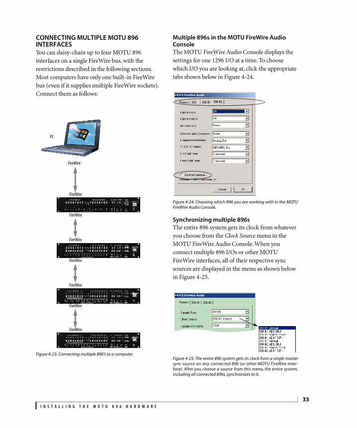
I N S T A L L I N G T H E M O T U 8 9 6 H A R D W A R E
33
CONNECTING MULTIPLE MOTU 896 INTERFACESYou can daisy-chain up to four MOTU 896
interfaces on a single FireWire bus, with the
restrictions described in the following sections.
Most computers have only one built-in FireWire
bus (even if it supplies multiple FireWire sockets).
Connect them as follows:
Figure 4-23: Connecting multiple 896’s to a computer.
Multiple 896s in the MOTU FireWire Audio ConsoleThe MOTU FireWire Audio Console displays the
settings for one 1296 I/O at a time. To choose
which I/O you are looking at, click the appropriate
tabs shown below in Figure 4-24.
Figure 4-24: Choosing which 896 you are working with in the MOTUFireWire Audio Console.
Synchronizing multiple 896sThe entire 896 system gets its clock from whatever
you choose from the Clock Source menu in the
MOTU FireWire Audio Console. When you
connect multiple 896 I/Os or other MOTU
FireWire interfaces, all of their respective sync
sources are displayed in the menu as shown below
in Figure 4-25.
Figure 4-25: The entire 896 system gets its clock from a single mastersync source on any connected 896 (or other MOTU FireWire inter-face). After you choose a source from this menu, the entire system,including all connected 896s, synchronizes to it.
PC
FireWire
FireWire
FireWire
FireWire
FireWire
FireWire
FireWire
FireWire
!896 Manual/Win Page 33 Tuesday, November 27, 2001 5:02 PM

I N S T A L L I N G T H E M O T U 8 9 6 H A R D W A R E
34
Word clock connections are not necessaryEach 896 in the system gets its clock from the
Audio Wire cable connection (unless it is the
master clock itself). There is no need to make word
clock connections between multiple 896 I/Os.
Connecting a MOTU 828You can add a MOTU 828 to the end of a MOTU
896 FireWire daisy chain (because the 828 has only
one FireWire port), or you can mix and match
multiple 896’s and 828’s using a standard FireWire
hub. Up to four interfaces can be combined on one
FireWire bus.
Operating multiple 896 interfaces at high sample ratesFour MOTU 896 interfaces (or mixed and matched
896 and 828 interfaces) can operate at 44.1 kHz or
48 kHz on a single FireWire bus. When operating
896 interfaces at a high sample rate (88.2 or
96 kHz), ADAT optical becomes disabled (because
it does not support these sample rates). As a result,
the 896 carries 10 channels of audio (8 analog and
2 AES/EBU). At a sample rate of 88.2 kHz allows
you to run up to three 986s (with 10 channels
each). At 96 kHz, you can operate no more than
two 896s on a single FireWire bus.
Adding additional interfaces with a second FireWire busThird-party FireWire bus expansion products in
the form of a cardbus (“PC card”) adaptor or PCI
card allow you to add a second FireWire bus to
your computer. In may be possible to add
additional MOTU FireWire interfaces connected
to such a third-party product, depending on the
performance of the product and the performance
of your host computer.
Managing the IDs of multiple interfacesAs shown in Figure 4-24 on page 33, multiple
MOTU 896 interfaces are identified by number (#1,
#2, #3, etc.) Interfaces are ID’d (given a number) by
the order in which they are first powered up after
being connected. This information is stored in the
MOTU FireWire Audio preferences file. Once ID’d,
they retain the same number regardless of the
order in which they are powered up. You can
disable an interface at any time with the Disable
interface option shown in Figure 4-24 on page 33.
Doing so frees up the FireWire bandwidth required
by the interface without turning it off. Switching off
an interface accomplishes the same thing. To get
the MOTU FireWire Audio Console to forget about
an interface entirely, you’ll see a Forget button in
the MOTU FireWire Audio Console. Just click the
Forget button and the MOTU FireWire Audio
Console will no longer consider the interface to be
present but off line (turned off).
!896 Manual/Win Page 34 Tuesday, November 27, 2001 5:02 PM

CHAPTER
35
5 MOTU FireWire Audio Console
OVERVIEWThe MOTU FireWire Audio Console provides
access to all MOTU 896 settings.
Accessing the MOTU 896 settings . . . . . . . . . . . .35
MOTU 896 Settings . . . . . . . . . . . . . . . . . . . . . . . .36
General tab settings . . . . . . . . . . . . . . . . . . . . . . . .36
896 tab settings . . . . . . . . . . . . . . . . . . . . . . . . . . . .36
Sample Rate . . . . . . . . . . . . . . . . . . . . . . . . . . . . . . .36
Clock Source . . . . . . . . . . . . . . . . . . . . . . . . . . . . . .36
Samples Per Buffer . . . . . . . . . . . . . . . . . . . . . . . . .38
Enable Pedal . . . . . . . . . . . . . . . . . . . . . . . . . . . . . . .38
Enable full Wave support for legacy (MME) software . . . . . . . . . . . . . . . . . . . . . . . . . . . . . . . . . . .38
Enable multichannel wave synchronization . . .39
Optical input/output . . . . . . . . . . . . . . . . . . . . . . .39
Monitor input — CueMix™ Plus . . . . . . . . . . . . .39
Sample Rate Conversion . . . . . . . . . . . . . . . . . . . .39
Programmable Meters . . . . . . . . . . . . . . . . . . . . . .40
AES/EBU Meters . . . . . . . . . . . . . . . . . . . . . . . . . . .40
Clip Hold Time . . . . . . . . . . . . . . . . . . . . . . . . . . . .40
Peak Hold Time. . . . . . . . . . . . . . . . . . . . . . . . . . . . 40
Disable Interface option . . . . . . . . . . . . . . . . . . . . 40
Word Out . . . . . . . . . . . . . . . . . . . . . . . . . . . . . . . . . 41
Monitoring live input. . . . . . . . . . . . . . . . . . . . . . . 41
ACCESSING THE MOTU 896 SETTINGSThere are several ways to access the MOTU
FireWire Audio Console settings:
� From the Windows Start menu, choose
Programs>MOTU>MOTU FireWire Audio Console
� From within Cubase (Version 5 or higher), click
the ASIO Control Panel button in the System Setup
dialog as shown in Figure 6-2 on page 44.
� From within other ASIO-compatible programs,
refer to their documentation.
It doesn’t matter which way you access the MOTU
!896 Manual/Win Page 35 Tuesday, November 27, 2001 5:02 PM

M O T U F I R E W I R E A U D I O C O N S O L E
36
MOTU 896 SETTINGS
Figure 5-1: The MOTU FireWire Audio Console gives you access to allof the settings in the MOTU 896 hardware.
General tab settingsThe General tab provides settings that apply
globally to all connected MOTU 896 interfaces
(and other MOTU FireWire audio interfaces).
896 tab settingsThe 896 tab provides settings that apply to a
specific 896 interface. If you have several 896’s (or
other MOTU FireWire audio interfaces)
connected, you’ll see a separate tab for each one.
Sample RateChoose the desired Sample Rate for recording and
playback. The MOTU 896 can operate at 44.1 KHz
(the standard rate for compact disc audio),
48 KHz, 88.2 kHz or 96 kHz.
☛ Mismatched sample rates cause distortion and
crackling. If you hear this sort of thing, check the
sample rate settings in your hardware and here in
the MOTU FireWire Audio Console.
Clock SourceThe Clock Source determines the digital audio clock
that the MOTU 896 will use as its time base. For a
complete explanation of synchronization issues,
see “Making sync connections” on page 21. The
following sections briefly discuss each clock source
setting.
Internal
Use the Internal setting when you want the MOTU
896 to operate under its own digital audio clock.
For example, you may be in a situation where all
you are doing is playing tracks off hard disk in your
digital audio software on the computer. In a
situation like this, you most often don’t need to
reference an external clock of any kind.
Another example is transferring a mix to DAT. You
can operate the MOTU 896 system on its internal
clock, and then slave the DAT deck to the MOTU
896 via the AES/EBU connection (usually DAT
decks slave to their AES/EBU input when you
choose the AES/EBU input as their record source).
If you would like help determining if this is the
proper clock setting for your situation, see “Do you
need a synchronizer?” on page 22.
With ADAT devices, however, you usually want an
external digital audio synchronizer, such as the
MIDI Timepiece AV or Digital Timepiece, to be the
!896 Manual/Win Page 36 Tuesday, November 27, 2001 5:02 PM
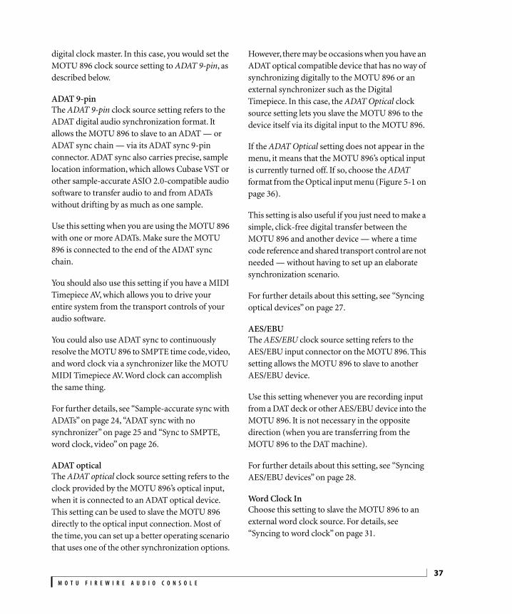
M O T U F I R E W I R E A U D I O C O N S O L E
37
digital clock master. In this case, you would set the
MOTU 896 clock source setting to ADAT 9-pin, as
described below.
ADAT 9-pin
The ADAT 9-pin clock source setting refers to the
ADAT digital audio synchronization format. It
allows the MOTU 896 to slave to an ADAT — or
ADAT sync chain — via its ADAT sync 9-pin
connector. ADAT sync also carries precise, sample
location information, which allows Cubase VST or
other sample-accurate ASIO 2.0-compatible audio
software to transfer audio to and from ADATs
without drifting by as much as one sample.
Use this setting when you are using the MOTU 896
with one or more ADATs. Make sure the MOTU
896 is connected to the end of the ADAT sync
chain.
You should also use this setting if you have a MIDI
Timepiece AV, which allows you to drive your
entire system from the transport controls of your
audio software.
You could also use ADAT sync to continuously
resolve the MOTU 896 to SMPTE time code, video,
and word clock via a synchronizer like the MOTU
MIDI Timepiece AV. Word clock can accomplish
the same thing.
For further details, see “Sample-accurate sync with
ADATs” on page 24, “ADAT sync with no
synchronizer” on page 25 and “Sync to SMPTE,
word clock, video” on page 26.
ADAT optical
The ADAT optical clock source setting refers to the
clock provided by the MOTU 896’s optical input,
when it is connected to an ADAT optical device.
This setting can be used to slave the MOTU 896
directly to the optical input connection. Most of
the time, you can set up a better operating scenario
that uses one of the other synchronization options.
However, there may be occasions when you have an
ADAT optical compatible device that has no way of
synchronizing digitally to the MOTU 896 or an
external synchronizer such as the Digital
Timepiece. In this case, the ADAT Optical clock
source setting lets you slave the MOTU 896 to the
device itself via its digital input to the MOTU 896.
If the ADAT Optical setting does not appear in the
menu, it means that the MOTU 896’s optical input
is currently turned off. If so, choose the ADAT
format from the Optical input menu (Figure 5-1 on
page 36).
This setting is also useful if you just need to make a
simple, click-free digital transfer between the
MOTU 896 and another device — where a time
code reference and shared transport control are not
needed — without having to set up an elaborate
synchronization scenario.
For further details about this setting, see “Syncing
optical devices” on page 27.
AES/EBU
The AES/EBU clock source setting refers to the
AES/EBU input connector on the MOTU 896. This
setting allows the MOTU 896 to slave to another
AES/EBU device.
Use this setting whenever you are recording input
from a DAT deck or other AES/EBU device into the
MOTU 896. It is not necessary in the opposite
direction (when you are transferring from the
MOTU 896 to the DAT machine).
For further details about this setting, see “Syncing
AES/EBU devices” on page 28.
Word Clock In
Choose this setting to slave the MOTU 896 to an
external word clock source. For details, see
“Syncing to word clock” on page 31.
!896 Manual/Win Page 37 Tuesday, November 27, 2001 5:02 PM

M O T U F I R E W I R E A U D I O C O N S O L E
38
Samples Per BufferA sample buffer is a small part of computer memory
that briefly holds digital audio samples as they are
passed between the computer and the MOTU 896.
The Samples Per Buffer setting lets you control the
size of these buffers in the MOTU FireWire Audio
Driver. A higher setting reduces the processing
load on your computer; a lower setting reduces
monitoring latency, which is the slight delay you
hear when patching live audio through the MOTU
896 and your audio software. (See “Monitoring live
input” on page 41 for further explanation.) For
example, you might want to listen to the vocals you
are recording with a little bit of reverb on them
from a plug-in in your audio software. The signal
that gets recorded to disk is ‘dry’, but the signal in
your headphones is ‘wet’. Since the vocal material
recorded to disk is dry, you then have the flexibility
to apply real-time reverb to the track after
recording and change it at any time (since the
reverb is not ‘printed’ in the track). You can even
automate changes to plug-in effects over time (if
your software supports plug-in automation).
At a sample rate of 44.1 kHz, a Samples Per Buffer
setting of 512 produces a round-trip delay
(monitoring latency) of approximately 23
milliseconds (ms). A setting of 256 produces
monitoring latency of around 12-13 ms, and the
delay starts to become inaudible.
Monitoring latency has no effect on recording
It is important to note that monitoring latency only
applies to the live signal as it is being monitored. It
has no effect whatsoever on the timing accuracy of
the material being recorded to hard disk. The
system is precisely calibrated to record and play
back hard disk audio perfectly on time.
Choosing the right ‘Samples per buffer’ setting
If you would like to process live inputs with plug-in
effects in your software (such as putting a reverb
plug-in on a vocal mic input or a guitar amp
simulation plug-in on your guitar signal), make the
Samples Per Buffer setting as low as possible. How
low you can go depends on how fast your computer
is and how much plug-in processing (and other
processor-intensive tasks) you are using in your
recording project. Try settings below 512 and if
your computer begins to act sluggish, try raising
them again to the next highest buffer setting until
the computer feels responsive. If your computer
doesn’t allow you to go low enough, try cueMix™
Plus monitoring (“Monitor input — CueMix™
Plus” below) and then apply plug-in processing to
the disk track after it has been recorded.
Changing the ‘Samples Per Buffer’ setting
If you are at a point in your recording project where
you are not currently working with live, patched-
thru material (e.g. you’re not recording vocals),
switch to a higher Samples Per Buffer setting.
Depending on your computer’s CPU speed, you
might find that settings in the middle work best
and that your computer is much more responsive.
CueMix ™Plus monitoring
The MOTU 896’s CueMix™ Plus no-latency
monitoring feature completely eliminates
monitoring latency. For further information, see
“Monitoring live input” on page 41.
Enable PedalCheck the Enable Pedal option if a foot switch is
connected to the MOTU 896 and you would like to
trigger recording punch in/out (or other software
functions) with it. Use the Set buttons to determine
what keystroke is trigger by the pedal-up and
pedal-down positions. You can assign the pedal to
any two keystrokes you wish. (You are not
restricted to punch in/out.)
Enable full Wave support for legacy (MME) softwareWindows only exposes the first two channels of a
multi-channel WDM audio stream to applications
which use the legacy (MME) multimedia interface.
!896 Manual/Win Page 38 Tuesday, November 27, 2001 5:02 PM

M O T U F I R E W I R E A U D I O C O N S O L E
39
The Enable full Wave support for legacy (MME)
software (less efficient) option forces the MOTU 896
multimedia driver to expose all channels as stereo
pairs, providing full MME support.
If your host audio software does not directly
support WDM audio and instead only supports
legacy MME drivers, use this option to access
multiple MOTU 896 input and output channels.
If your host audio software does directly support
WDM audio, leave this option unchecked for
optimal performance.
This option is only available when the multimedia
driver has been installed, and it defaults to being
not checked.
Enable multichannel wave synchronizationThis option should be left on. There are only a few
rare cases in which you would want to turn it off.
For details, consult the on-line tech support
database at www.motu.com.
Optical input/outputThe Optical input and Optical output settings let
you choose between ADAT (‘lightpipe’) or OFF.
Turning it off frees up FireWire bandwidth. In
other words, it opens up resources on the FireWire
bus for other devices connected via FireWire.
Monitor input — CueMix™ PlusThe Monitor input settings enables the MOTU 896
CueMix™ Plus feature (Figure 5-4 on page 41),
which lets you route an analog or AES/EBU input
or input pair directly to the MOTU 896 main outs,
where it is mixed with the signal on the main outs.
Routing occurs with virtually no monitoring
latency (audible delay), and the signal is passed
through dry (with no signal processing of any
kind). In addition, the CueMix Plus signal volume
can be controlled (relative to the main mix volume)
with the Monitor Level knob on the MOTU 896
front panel. For information about other ways to
handle input monitoring, see “Monitoring live
input” on page 41.
Sample Rate ConversionThis option lets you control AES/EBU sample rate
conversion. Each option is explained below.
None
No sample rate conversion occurs. Both the
AES/EBU input and output match the sample rate
of the 896’s system clock.
AES In
The AES/EBU input locks to the sample rate of the
input signal (whatever it happens to be) and
converts it to the 896 system clock rate. The Rate
Conversion LEDs on the 896 front panel indicate
the incoming sample rate and that rate conversion
is occurring.
AES Out slave to AES in
To make the AES/EBU output sample rate match
the sample rate currently being received by the
896’s AES/EBU input, choose AES Input. This
setting requires a connection to the 896’s AES/EBU
input from a device that is transmitting an
AES/EBU clock signal.
☛ Be careful when both the 896’s AES/EBU input
and output are connected to the same external
device: this option is likely to create a clock loop.
☛ When you are using the AES/EBU input as a
clock source for sample rate conversion on the
AES/EBU output, you cannot use the AES/EBU
input for audio input.
AES Out x 2 / AES Out ÷ 2
Choose one of these sample rates when the desired
AES/EBU output rate needs to be twice the 896
system clock rate (when the system clock is at
either 44.1 or 48 kHz) or half the system clock rate
(when the system clock is at 88.2 or 96 kHz). Either
way, the AES/EBU output remains resolved to the
!896 Manual/Win Page 39 Tuesday, November 27, 2001 5:02 PM

M O T U F I R E W I R E A U D I O C O N S O L E
40
896 system clock. For further details about this
option, see “Syncing AES/EBU devices” on
page 28.
Programmable MetersThis option lets you choose which bank you wish
to monitor with the eight programmable meters on
the MOTU 896 front panel. Your choices are:
Analog Out, ADAT In or ADAT Out.
AES/EBU MetersThis option lets you choose to monitor either
AES/EBU input or output with the programmable
AES/EBU meters on the MOTU 896 front panel.
Clip Hold TimeThe Clip Hold Time option controls how long the
top red LED remains illuminated after clipping
occurs (see Figure 5-2 below).
Figure 5-2: The Clip Hold Time option.
Peak Hold TimeThe 896 front-panel level meters support standard
peak/hold metering, where the LED for the highest
level recently measured on the channel remains
illuminated for a brief period of time while the rest
of the LEDs below it remain fully dynamic. The
Peak Hold Time controls how long the peak-hold
LED remain illuminated before going dark again.
Disable Interface optionCheck this option to temporarily take an interface
off line. Doing so frees up FireWire bandwidth for
other devices without turning off the disabled 896.
The ‘Clip Hold Time’ option controls how long this LED remains illuminated.
This LED lights up momentarily.
PC
2. Mic signal goes immedi-ately to the computer (dry, with no effects processing).
3. Mic signal is ‘patched thru’ back to the MOTU 896 with reverb or other plug-in effects, if any.
4. Mic signal (with plug-in processing, if any) is routed to the main outs (or other MOTU 896 outputs that you’ve chosen in your audio software).
Figure 5-3: There are two ways to monitor live audio inputs with the MOTU 896: 1) through the computer or 2) via CueMix™ Plus hardwaremonitoring. This diagram shows method 1 (through the computer). When using this method, use the MOTU 896’s ‘Samples Per Buffer’ settingto reduce the slight delay you hear when monitoring the live input, but don’t lower it too much, or your computer will act sluggish.
1. Live input (from mic, guitar, etc.) enters the MOTU 896.
!896 Manual/Win Page 40 Tuesday, November 27, 2001 5:02 PM

M O T U F I R E W I R E A U D I O C O N S O L E
41
Word OutIf you are running a MOTU 896 interface at a high
sample rate (96 or 88.2), this option appears at the
bottom of the interface settings. It lets you choose a
word clock output rate that either matches the
global sample rate (e.g. 96 kHz) or halves the global
rate (e.g. 48 kHz instead of 96 kHz).
MONITORING LIVE INPUTThere are two ways to monitor live audio input with
the MOTU 896: 1) through the computer or 2) via
CueMix™ Plus hardware monitoring. Figure 5-3
on page 40 below shows method 1, which allows
you to add effects processing such as reverb and
guitar amp effects via plug-ins in your audio
software. See “Samples Per Buffer” on page 38 for
details about how to reduce — and possibly
eliminate — the audible monitoring delay that the
computer introduces.
Figure 5-4 shows how to use CueMix™ Plus
hardware-based monitoring, which lets you hear
what you are recording with no monitoring delay
and no computer-based effects processing. (You
can add effects later, after you’ve recorded the live
input as a disk track.) To learn more, see “Monitor
input — CueMix™ Plus” on page 39.
If the material you are recording is suitable, there is
a third way to monitor live input: use both methods
(Figure 5-3 and Figure 5-4) at the same time. For
example, you could route vocals to both the
computer (for a bit of reverb) and mix that
processed signal on the main outs with dry vocals
from CueMix Plus.
1. Live input (from mic, guitar, etc.) enters the MOTU 896.
2. CueMix™ Plus immediately patches the live mic signal directly to the main outs, completely bypassing the computer (dry, with no effects processing).
3. Mic signal is mixed with the main outs, and you can control the volume (relative to the rest of the mix) with the ‘monitor level’ knob on the front panel of the MOTU 896.
Figure 5-4: This diagram shows the signal flow when using CueMix™ Plus no-latency monitoring. Notice that this method does not allow youto process the live input with plug-ins in your audio software while it is being monitored. You can, however, add effects later — after recordingthe live input as a disk track. CueMix™ Plus lets you hear what you are recording with no delay and no computer-based effects.
!896 Manual/Win Page 41 Tuesday, November 27, 2001 5:02 PM

M O T U F I R E W I R E A U D I O C O N S O L E
42
!896 Manual/Win Page 42 Tuesday, November 27, 2001 5:02 PM

CHAPTER
43
6 ASIO-compatible Audio Software
OVERVIEWThe MOTU 896 includes an ASIO driver that
provides multi-channel I/O with any ASIO-
compatible audio software.
What is ASIO? . . . . . . . . . . . . . . . . . . . . . . . . . . . . .43
Check the MOTU FireWire Audio Console. . . . . . . 43
Enable the MOTU FireWire Audio ASIO driver . .44
Number of audio channels . . . . . . . . . . . . . . . . . .44
Working with MOTU 896 inputs and outputs .45
Trimming the analog inputs . . . . . . . . . . . . . . . . .45
Changing MOTU 896 settings . . . . . . . . . . . . . . .45
Reducing delay when monitoring live inputs . .45
Audio clock source . . . . . . . . . . . . . . . . . . . . . . . . .46
Synchronization . . . . . . . . . . . . . . . . . . . . . . . . . . .46
MIDI Machine Control (MMC) . . . . . . . . . . . . . .47
24-bit operation. . . . . . . . . . . . . . . . . . . . . . . . . . . .47
WHAT IS ASIO?ASIO is an acronym for Audio Streaming Input and
Output. The ASIO MOTU FireWire Audio driver
allows the MOTU 896 to provide multi-channel
audio input and output for any audio application
that supports ASIO drivers.
Sample-accurate syncThe MOTU FireWire Audio ASIO driver supports
sample-accurate sync (via the MOTU 896’s ADAT
sync feature) for applications that support it.
Attention: Cubase VST usersCubase VST Version 5 is used for the examples in
this chapter. However, there is no significant
difference between the Version 5 examples shown
and what you see in Version 4. The basic
procedures are the same.
Attention: Other software usersCubase VST is used for the examples in this
chapter. However, the basic procedures are the
same and can be easily applied to any ASIO-
compatible software. Just follow the general
descriptions at the beginning of each main section
in this chapter. Consult your software
documentation for details about each topic, if
necessary.
If your audio software doesn’t support ASIOIf your host audio software does not support ASIO,
but instead supports WDM (or legacy Wave) audio
drivers, refer to the next chapter.
CHECK THE MOTU FIREWIRE AUDIO CONSOLEBefore you run your audio software, launch the
MOTU FireWire Audio Console to configure your
MOTU 896 hardware. The MOTU FireWire Audio
Console lets you choose the audio clock source,
!896 Manual/Win Page 43 Tuesday, November 27, 2001 5:02 PM

A S I O - C O M P A T I B L E A U D I O S O F T W A R E
44
and it lets you enable the optical input and output,
if needed. For details, see chapter 5, “MOTU
FireWire Audio Console” (page 35).
Figure 6-1: The MOTU FireWire Console gives you access to all of thesettings in the MOTU 896 hardware, including the clock source,optical I/O enable/disable and CueMix™ Plus monitor input(s).
ENABLE THE MOTU FIREWIRE AUDIO ASIO DRIVEROnce you’ve made the preparations described so
far in this chapter, you’re ready to run your audio
software and enable the MOTU FireWire Audio
driver. Check the audio system or audio hardware
configuration window in your software. There will
be a menu there that lets you choose among
various ASIO drivers that may be in your system.
Choose the MOTU 896 from this menu.
Enabling the MOTU FireWire Audio ASIO driver in CubaseTo activate the MOTU FireWire Audio ASIO driver
in Cubase:
1 Choose System from the Audio menu.
2 Choose MOTU FireWire Audio from the ASIO
device menu.
3 Make the other settings in the dialog as need for
your system and synchronization scenario.
Figure 6-2: Activating the MOTU FireWire Audio ASIO driver inCubase. The Audio Clock Source setting shown here is for the MOTU896. You can also choose the clock source in the MOTU FireWire AudioConsole.
NUMBER OF AUDIO CHANNELSBe sure to configure your audio software so that it
has enough audio channels (or voices) to cover the
18 channels of input and output provided by the
MOTU 896:
� 8 channels for analog I/O
� 2 channels for AES/EBU
� Zero or 8 channels for optical, depending on
whether you have optical turned off or on
For example, if you are using analog only, you only
need 8 channels. If you are using analog and
AES/EBU, you need 10 channels.
!896 Manual/Win Page 44 Tuesday, November 27, 2001 5:02 PM

A S I O - C O M P A T I B L E A U D I O S O F T W A R E
45
As another example, if you are using analog,
AES/EBU and ADAT optical, you need 18 channels
(the maximum number of simultaneous channels
provided by the MOTU 896).
In Cubase, set the number of channels in the
System dialog (as shown above in Figure 6-2).
WORKING WITH MOTU 896 INPUTS AND OUTPUTSOnce you’ve enabled the MOTU FireWire Audio
ASIO driver in your host audio software, MOTU
896 audio inputs and outputs will appear in your
software’s input/output menus, and you can set
them up and use them as any standard audio input
and output. If you don’t see the optical inputs
and/or outputs, check the MOTU FireWire Audio
Console to make sure they are turned on and set to
the format you require. If you don’t plan to use the
optical input or output, turn it off to conserve
computer bandwidth.
MOTU 896 inputs/outputs in CubaseOnce you’ve chosen the MOTU FireWire Audio
ASIO driver in the Audio System dialog, choose
Audio Inputs from the Audio menu to see the
MOTU 896 inputs. To activate them, click the
Active light next to each input. Once you’ve
activated the MOTU 896 inputs, you can then
assign them to Cubase audio channels in the
Monitor window in the usual fashion. MOTU 896
outputs appear in the Master window as output
assignments for the master fader and busses.
Figure 6-3: Use the output buttons at the bottom of each channelstrip to assign MOTU 896 outputs to busses. You can then assignchannels in the Monitor window to each bus as desired.
TRIMMING THE ANALOG INPUTSThe MOTU 896 analog inputs provide trim knobs
on the front panel. Use the level meters on the 896’s
front panel to calibrate these inputs before
recording. As you feed signal to the MOTU 896
analog input, adjust the input’s corresponding trim
knob on the front panel until peaks are as high as
possible without clipping (hitting zero dB).
USING A FOOT SWITCHUse a foot switch connected to the MOTU 896 to
trigger recording punch-in and punch-out, or any
other feature in your host audio software that is
assigned to a computer keystroke.
CHANGING MOTU 896 SETTINGSYou can change the MOTU 896 settings at any time
by accessing the MOTU FireWire Audio Console.
(See “Accessing the MOTU 896 settings” on
page 35.)
REDUCING DELAY WHEN MONITORING LIVE INPUTSIf you have live audio inputs connected to the
MOTU 896, such as MIDI synthesizers, samplers,
microphones or other live instruments, you might
hear a slight delay when their audio is being
monitored through your MOTU 896 hardware and
your host audio program. (In Cubase, this delay is
!896 Manual/Win Page 45 Tuesday, November 27, 2001 5:02 PM
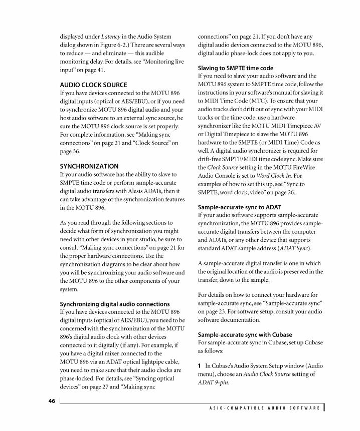
A S I O - C O M P A T I B L E A U D I O S O F T W A R E
46
displayed under Latency in the Audio System
dialog shown in Figure 6-2.) There are several ways
to reduce — and eliminate — this audible
monitoring delay. For details, see “Monitoring live
input” on page 41.
AUDIO CLOCK SOURCEIf you have devices connected to the MOTU 896
digital inputs (optical or AES/EBU), or if you need
to synchronize MOTU 896 digital audio and your
host audio software to an external sync source, be
sure the MOTU 896 clock source is set properly.
For complete information, see “Making sync
connections” on page 21 and “Clock Source” on
page 36.
SYNCHRONIZATIONIf your audio software has the ability to slave to
SMPTE time code or perform sample-accurate
digital audio transfers with Alesis ADATs, then it
can take advantage of the synchronization features
in the MOTU 896.
As you read through the following sections to
decide what form of synchronization you might
need with other devices in your studio, be sure to
consult “Making sync connections” on page 21 for
the proper hardware connections. Use the
synchronization diagrams to be clear about how
you will be synchronizing your audio software and
the MOTU 896 to the other components of your
system.
Synchronizing digital audio connectionsIf you have devices connected to the MOTU 896
digital inputs (optical or AES/EBU), you need to be
concerned with the synchronization of the MOTU
896’s digital audio clock with other devices
connected to it digitally (if any). For example, if
you have a digital mixer connected to the
MOTU 896 via an ADAT optical lightpipe cable,
you need to make sure that their audio clocks are
phase-locked. For details, see “Syncing optical
devices” on page 27 and “Making sync
connections” on page 21. If you don’t have any
digital audio devices connected to the MOTU 896,
digital audio phase-lock does not apply to you.
Slaving to SMPTE time codeIf you need to slave your audio software and the
MOTU 896 system to SMPTE time code, follow the
instructions in your software’s manual for slaving it
to MIDI Time Code (MTC). To ensure that your
audio tracks don’t drift out of sync with your MIDI
tracks or the time code, use a hardware
synchronizer like the MOTU MIDI Timepiece AV
or Digital Timepiece to slave the MOTU 896
hardware to the SMPTE (or MIDI Time) Code as
well. A digital audio synchronizer is required for
drift-free SMPTE/MIDI time code sync. Make sure
the Clock Source setting in the MOTU FireWire
Audio Console is set to Word Clock In. For
examples of how to set this up, see “Sync to
SMPTE, word clock, video” on page 26.
Sample-accurate sync to ADATIf your audio software supports sample-accurate
synchronization, the MOTU 896 provides sample-
accurate digital transfers between the computer
and ADATs, or any other device that supports
standard ADAT sample address (ADAT Sync).
A sample-accurate digital transfer is one in which
the original location of the audio is preserved in the
transfer, down to the sample.
For details on how to connect your hardware for
sample-accurate sync, see “Sample-accurate sync”
on page 23. For software setup, consult your audio
software documentation.
Sample-accurate sync with CubaseFor sample-accurate sync in Cubase, set up Cubase
as follows:
1 In Cubase’s Audio System Setup window (Audio
menu), choose an Audio Clock Source setting of
ADAT 9-pin.
!896 Manual/Win Page 46 Tuesday, November 27, 2001 5:02 PM

A S I O - C O M P A T I B L E A U D I O S O F T W A R E
47
2 In Cubase’s Synchronization window, set the
Sync Source Time Base to ASIO 2.0 as shown
below:
Figure 6-4: Setting up sample-accurate sync via ASIO 2.
3 Enable SYNC in the Controls window.
Figure 6-5: Enabling the SYNC button.
4 Begin playback from the sample-accurate sync
source (ADAT, etc.) Transport control is handled
by the sample-accurate sync source.
The ASIO 2.0 MMC setting in CubaseThe Timecode Base menu shown above in
Figure 6-4 includes a setting called ASIO 2.0 MMC,
which provides sample-accurate transport control
of the MOTU MIDI Timepiece AV (or other
MMC-compatible synchronizer) from the
transport buttons in Cubase itself.
MIDI MACHINE CONTROL (MMC)If your audio software supports MIDI Machine
Control (MMC), and you have ADATs and a
MMC-compatible ADAT synchronizer like the
MIDI Timepiece AV, you can control everything
from the transport controls and cueing features in
your audio software (like the playback wiper, etc.)
See “Sample-accurate sync to ADAT” on page 46
for details on how to set this up.
24-BIT OPERATIONYour MOTU 896 hardware fully supports 24-bit
recording in any audio software that supports it.
Simply enable 24-bit operation as instructed by the
software. The MOTU 896 system always supplies
the software with a 24-bit data stream, and when
you enable 24-bit operation, it simply uses all
24-bits supplied by the MOTU 896 hardware.
!896 Manual/Win Page 47 Tuesday, November 27, 2001 5:02 PM

A S I O - C O M P A T I B L E A U D I O S O F T W A R E
48
!896 Manual/Win Page 48 Tuesday, November 27, 2001 5:02 PM

CHAPTER
49
7 Windows Multimedia-compatible Audio Software
OVERVIEWThe MOTU FireWire Audio WDM driver provides
standard multi-channel input and output for audio
software running under Windows 2000, Windows
Me or Windows XP.
WDM and Wave driver compatibility . . . . . . . . .49
Installing the MOTU FireWire Audio WDM driver . . . . . . . . . . . . . . . . . . . . . . . . . . . . . . . . . . . . .49
Enabling Wave (MME) compatibility . . . . . . . . .49
Making settings in the MOTU FireWire Audio Console . . . . . . . . . . . . . . . . . . . . . . . . . . . . . . . . . . .49
Enabling the MOTU FireWire Audio WDM driver . . . . . . . . . . . . . . . . . . . . . . . . . . . . . . . . . . . . .50
Working with MOTU 896 inputs and outputs .51
Trimming the analog inputs . . . . . . . . . . . . . . . . .51
Changing MOTU 896 settings . . . . . . . . . . . . . . .51
Reducing delay when monitoring live inputs . .51
Audio clock source . . . . . . . . . . . . . . . . . . . . . . . . .51
Synchronization . . . . . . . . . . . . . . . . . . . . . . . . . . .52
24-bit operation. . . . . . . . . . . . . . . . . . . . . . . . . . . .52
WDM AND WAVE DRIVER COMPATIBILITYWDM is an acronym for Windows Driver Model.
The MOTU FireWire Audio WDM driver allows
the MOTU 896 to provide multi-channel audio
input and output for any audio application that
supports WDM audio drivers.
Attention: Cakewalk usersCakewalk SONAR is used for the WDM driver
setup examples in this chapter.
Attention: other software usersCakewalk’s SONAR software is used for the WDM
driver setup examples in this chapter. However, the
basic procedures are the same and can be easily
applied to any WDM-compatible software. Just
follow the general descriptions at the beginning of
each main section in this chapter. Consult your
software documentation for details about each
topic, if necessary.
INSTALLING THE MOTU FIREWIRE AUDIO WDM DRIVERThe MOTU 896 installer CD-ROM installs the
MOTU FireWire Audio WDM driver into
Windows for you. That’s pretty much all the
preparation you need. See chapter 3,
“IMPORTANT! Run the MOTU 896 Software
Installer First” (page 15).
ENABLING WAVE (MME) COMPATIBILITYIf your host audio software does not yet support
Windows 2000 WDM drivers, you need to enable
Wave driver compatibility in the MOTU FireWire
Audio WDM driver so that all of the MOTU 896’s
inputs and outputs show up in your software. For
details, see “Enable full Wave support for legacy
(MME) software” on page 38.
☛ If your host audio software does support
WDM audio drivers, don’t enable Wave driver
compatibility.
MAKING SETTINGS IN THE MOTU FIREWIRE AUDIO CONSOLEBefore you run your audio software, launch the
MOTU FireWire Audio Console to configure your
MOTU 896 hardware. The MOTU FireWire Audio
Console lets you choose the audio clock source,
and it lets you enable the optical input and output,
if needed. For details, see chapter 5, “MOTU
FireWire Audio Console” (page 35).
!896 Manual/Win Page 49 Tuesday, November 27, 2001 5:02 PM

W I N D O W S M U L T I M E D I A - C O M P A T I B L E A U D I O S O F T W A R E
50
Figure 7-1: The MOTU FireWire Audio Console gives you access to allof the settings in the MOTU 896 hardware, including the clock source,optical I/O enable/disable and CueMix™ Plus monitor input(s).
ENABLING THE MOTU FIREWIRE AUDIO WDM DRIVEROnce you’ve made the preparations described so
far in this chapter, you’re ready to run your audio
software and enable the MOTU FireWire Audio
WDM driver. Check the audio system or audio
hardware configuration window in your software.
Enabling the MOTU FireWire Audio WDM driver in SONARTo activate the MOTU FireWire Audio WDM
driver in SONAR:
1 Choose Audio Options from the Options menu.
2 Click the Drivers tab.
3 Highlight the MOTU 896 inputs and outputs
that you wish to use and unhighlight the ones you
don’t as shown in Figure 7-2.
Figure 7-2: Activating the MOTU FireWire Audio driver in SONAR byhighlighting inputs and outputs.
Other audio settings in SONARThere are a few other settings in SONAR that
impact MOTU 896 operation:
1 In the Audio Options window, click the General
tab.
2 Choose a MOTU 896 input and output for
recording and playback timing as shown below in
Figure 7-3. It doesn’t matter which input or output
you choose.
!896 Manual/Win Page 50 Tuesday, November 27, 2001 5:02 PM

W I N D O W S M U L T I M E D I A - C O M P A T I B L E A U D I O S O F T W A R E
51
Figure 7-3: Make sure you have chosen a MOTU 896 input and outputfor the playback and recording timing master settings.
3 In the Audio Options window, click the Driver
Profiles tab and set the Stream > 16 bit data as
option to 4 bytes left-justified as shown below in
Figure 7-4.
Figure 7-4: Setting the streaming option in Cakewalk’s SONAR.
WORKING WITH MOTU 896 INPUTS AND OUTPUTSOnce you’ve enabled the MOTU FireWire Audio
WDM driver in your host audio software, MOTU
896 audio inputs and outputs will appear in your
software’s input/output menus, and you can set
them up and use them as any standard audio input
and output. If you don’t see the optical inputs and/
or outputs, check the MOTU FireWire Audio
Console to make sure they are turned on. If you
don’t plan to use the optical input or output, turn it
off to conserve computer bandwidth.
TRIMMING THE ANALOG INPUTSThe MOTU 896 analog inputs provide trim knobs
on the front panel. Use the level meters on the front
panel of the 896 to calibrate these inputs before
recording. As you feed signal to the MOTU 896
analog input, adjust the input’s corresponding trim
knob on the front panel of the MOTU 896 until
peaks are as high as possible without clipping
(hitting zero dB).
CHANGING MOTU 896 SETTINGSYou can change the MOTU 896 settings at any time
by accessing the MOTU FireWire Audio Console.
(See “Accessing the MOTU 896 settings” on
page 35.)
REDUCING DELAY WHEN MONITORING LIVE INPUTSIf you have live audio inputs connected to the
MOTU 896, such as MIDI synthesizers, samplers,
microphones or other live instruments, you might
hear a slight delay when their audio is being
monitored through your MOTU 896 hardware and
your host audio program. There are several ways to
reduce — and eliminate — this audible monitoring
delay. For details, see “Monitoring live input” on
page 41.
AUDIO CLOCK SOURCEIf you have devices connected to the MOTU 896
digital inputs (optical or AES/EBU), or if you need
to synchronize MOTU 896 digital audio and your
host audio software to an external sync source, be
sure the MOTU 896 clock source is set properly.
For complete information, see “Making sync
connections” on page 21 and “Clock Source” on
page 36.
!896 Manual/Win Page 51 Tuesday, November 27, 2001 5:02 PM
W I N D O W S M U L T I M E D I A - C O M P A T I B L E A U D I O S O F T W A R E
52
SYNCHRONIZATIONIf your audio software has the ability to slave to
SMPTE time code, then it can take advantage of the
synchronization features in the MOTU 896.
As you read through the following sections to
decide what form of synchronization you might
need with other devices in your studio, be sure to
consult “Making sync connections” on page 21 for
the proper hardware connections. Use the
synchronization diagrams to be clear about how
you will be synchronizing your audio software and
the MOTU 896 to the other components of your
system.
Synchronizing digital audio connectionsIf you have devices connected to the MOTU 896
digital inputs (optical or AES/EBU), you need to be
concerned with the synchronization of the MOTU
896’s digital audio clock with other devices
connected to it digitally (if any). For example, if
you have a digital mixer connected to the
MOTU 896 via an ADAT optical light pipe cable,
you need to make sure that their audio clocks are
phase-locked. For details, see “Syncing optical
devices” on page 27 and “Making sync
connections” on page 21. If you don’t have any
digital audio devices connected to the MOTU 896,
digital audio phase-lock does not apply to you.
Slaving to SMPTE time codeIf you need to slave your audio software and the
MOTU 896 system to SMPTE time code, follow the
instructions in your software’s manual for slaving it
to MIDI Time Code (MTC). To ensure that your
audio tracks don’t drift out of sync with your MIDI
tracks or the time code, use a hardware
synchronizer like the MOTU MIDI Timepiece AV
or Digital Timepiece to slave the MOTU 896
hardware to the SMPTE (or MIDI Time) Code as
well. A digital audio synchronizer is required for
drift-free SMPTE/MIDI time code sync. Make sure
the Clock Source setting in the MOTU FireWire
Audio Console is set to Word Clock In. For
examples of how to set this up, see “Sync to
SMPTE, word clock, video” on page 26.
24-BIT OPERATIONYour MOTU 896 hardware fully supports 24-bit
recording in any audio software that supports it.
Simply enable 24-bit operation as instructed by the
software. The MOTU 896 system always supplies
the software with a 24-bit data stream, and when
you enable 24-bit operation, it simply uses all
24-bits supplied by the MOTU 896 hardware.
!896 Manual/Win Page 52 Tuesday, November 27, 2001 5:02 PM

CHAPTER
53
8 Performance Tips & Troubleshooting
CD player will not play through the MOTU 896Playback from an audio CD on the PC requires a
physical connection between the CD player and
your sound card. The MOTU 896 does not have an
internal CD connection.
Why does the start sound not play through the MOTU 896? The MOTU 896 will only playback audio at a
sampling rate of 44.1 kHz, or 48 kHz
The computer freezes when it starts upIf the computer is unable to boot up, it may be a
conflict with the WDM Driver. As soon as the
computer boots up, Windows will try and initialize
the WDM Driver. If this fails, your computer will
hang. To determine if the WDM Driver is the
problem, boot up in Safe Mode or remove the
MOTU Audio software with the Add/Remove
Programs Control Panel then restart. Reinstall the
MOTU 896 software and choose only to install the
MOTU FireWire Audio ASIO driver, not the WDM
Driver. Restart again.
‘New hardware detected’ windowIf you connect your MOTU 896 before running the
MOTU 896 Software Installer CD, Windows will
prompt you that new hardware has been detected.
Cancel this, and run the MOTU 896 Software
Installer, rather than allowing Windows to locate
the drivers.
Audio in Cakewalk or SONAR speeds up or slows downThis could be caused by having incorrect SMPTE/
MTC Sync settings when you record audio into
Cakewalk. These settings are located at the bottom
of the Advanced Tab in the Audio Options dialog
box, accessed from Cakewalk’s Tools menu. Make
sure that you have the SMPTE/MTC Sync set to
“Trigger and Freewheel” before recording audio
while slaved to external time code.
MOTU 896 inputs and outputs are not available in Cakewalk or SONARMake sure that the inputs and/or outputs that you
want to use are enabled in Cakewalk or SONAR.
MOTU 882 inputs and outputs are not available in CubaseMake sure that the inputs and outputs are enabled
in Cubase.
Sound Forge and ‘Smooth Scroll’If the Smooth Scroll option under the Options
menu is turned on, you may experience clicks and
pops or other anomalies in the audio playback.
This gets worse as you zoom in more to the
waveform while playing. For the best quality
playback, turn this option off.
ADATs - converting 48kHz tracks to 44.1kHzIf the audio on your ADAT tape was recorded at
48kHz, then you must transfer that audio into your
host software at 48kHz. If you plan to digitally mix
this data and burn an audio CD, you must convert
your audio to 44.1kHz with your host software.
Once you sample rate convert your audio to
44.1kHz, you will have to set the sample rate in the
console back to 44100 so you can play the file. You
always want your digital clocks and sample rates to
match when dealing with any kind of digital audio
transfer or synchronizing.
No input from an ADATIf you are having trouble recording on your ADAT
from the MOTU 896, check the Digital input
setting. After power cycling, tape decks often come
!896 Manual/Win Page 53 Tuesday, November 27, 2001 5:02 PM

P E R F O R M A N C E T I P S & T R O U B L E S H O O T I N G
54
up configured to record from their analog inputs.
You won't be able to record from the MOTU 896 to
a tape deck until it is switched to digital input.
Alesis blackface (classic) ADAT optical syncIf you are using a Classic (black-faced) ADAT as a
sync master in your MOTU 896 setup, and you
want to record sample accurately into it, you must
configure it to use its internal clock, instead of
slaving to the optical input. To do this, hold down
the SET LOCATE button and press the DIGITAL
IN button. This will toggle the ADAT between
external sync (shown as "diG") and internal sync
("int"). Note that the ADAT will return to the "diG"
setting each time it is powered off.
Alesis ADAT track offsetIf you find that sample accurate transfers from an
ADAT are displaced by a small amount, try to reset
the ADAT to its factory default state. This is
accomplished by powering on the ADAT while
holding down the RECORD and PLAY keys simul-
taneously. The ADAT lx uses a 'soft' power key so lx
users will have to unplug and plug the ADAT lx
while holding down the RECORD and PLAY keys.
Clicks and pops under word clock syncMany problems result from incorrect word
clocking. It is essential that all digital devices in the
system be word locked. Consult chapter , “Making
sync connections” (page 21) for detailed
information on how to word clock your gear.
Whenever there is any weird noise or distortion,
suspect incorrect word lock.
Clicks and pops under ADAT SyncSometimes, the ADAT sync cable seems to be
plugged into the MOTU 896, and partially works -
but it isn’t really all the way in. This can cause clicks
when slaved to ADAT 9-pin. Make sure the cable is
seated firmly.
Clicks and pops due to hard drive problemsIf you have checked your clock settings sync cable
connections and you are still getting clicks and
pops in your audio, you may have a drive related
problem. Set the MOTU 896 Clock Source to
Internal and try recording just using the analog
inputs and outputs of the MOTU 896. If you
encounter the same artifacts you may want try
using another drive in your computer. Clicks and
pops can also occur when the drive is severely
fragmented, the disk drivers are outdated, or if you
are using a SCSI accelerator that is not optimally
configured for working with audio.
Connecting or powering gear during operationIt is not recommended that you connect/
disconnect, or power on/off devices connected to
the MOTU 896 while recording or playing back
audio. Doing so may cause a brief glitch in the
audio.
Monitoring - How to monitor inputs?Please refer to the documentation for the audio
application that you are using. If your application
does not support input monitoring, you will need
to use the MOTU 896’s hardware-based CueMix
Plus monitoring feature. Please see “Monitor input
— CueMix™ Plus” on page 39.
No optical inputs or outputs are available in host audio applicationCheck to make sure you have the desired optical
inputs and/or outputs enabled in the MOTU
FireWire Audio Console.
Controlling monitoring latencySee “Monitoring live input” on page 41.
CUSTOMER SUPPORTWe are happy to provide customer support to our
registered users. If you haven’t already done so,
please take a moment to complete the registration
card included with your MOTU 896 system. When
!896 Manual/Win Page 54 Tuesday, November 27, 2001 5:02 PM

P E R F O R M A N C E T I P S & T R O U B L E S H O O T I N G
55
we receive your card, you’ll be placed on our
mailing list for free software updates and
information about new products.
REPLACING DISKSIf your MOTU 896 software CD-ROM becomes
damaged and fails to provide you with fresh,
working copies of the program, our Customer
Support Department will be glad to replace it. You
can request a replacement disc by calling our
business office at (617) 576-2760 and asking for the
customer service department.
TECHNICAL SUPPORTIf you are unable, with your dealer’s help, to solve
problems you encounter with the MOTU 896
system, you may contact our technical support
department in one of the following ways:
� Tech support hotline: (617) 576-3066 (Monday
through Friday, 9 am to 6 pm EST)
� Tech support 24-hour fax line: (617) 354-3068
� Tech support email: [email protected]
� Web site: www.motu.com
Please provide the following information to help us
solve your problem as quickly as possible:
� The serial number of the MOTU 896 system.
This is printed on a sticker placed on the bottom of
the MOTU 896 rack unit. You must be able to
supply this number to receive technical support.
� Software version numbers for the audio software
you are using, the MOTU FireWire Audio WDM
Driver, MOTU FireWire Audio ASIO driver, etc.
� A brief explanation of the problem, including the
exact sequence of actions which cause it, and the
contents of any error messages which appear on the
screen.
!896 Manual/Win Page 55 Tuesday, November 27, 2001 5:02 PM

P E R F O R M A N C E T I P S & T R O U B L E S H O O T I N G
56
!896 Manual/Win Page 56 Tuesday, November 27, 2001 5:02 PM

I N D E X
57
02R mixer 27connecting 20
1394 connector 6, 11, 1724-bit
3rd party software 47, 52analog recording 10optical 6recording 11
AAardvark Aard Sync 32ADAT 9-pin 10, 37ADAT lightpipe 27ADAT optical 6, 10
clock source setting 37connecting 18syncing with 36
ADAT Sync 10connector 6sample-accurate 23, 24, 25sync setting 37
AES In option (sample rate conversion) 39AES Out ÷ 2 option 39AES Out slave to AES in option 39AES Out x 2 option 39AES/EBU 10
clock source setting 37AES/EBU Meters option 40Analog inputs/outputs 6
converters 10making connections to 18trimming in 3rd party software 45,
51Analog metering 11ASIO 11, 15, 16, 43
ASIO 2.0 MMC option 47ASIO 2.0 option 47
ASIO Control Panel button 7, 35Audio
bit resolution 36AudioDesk
MOTU 828 settings 7sync settings 24, 25, 26
BBalanced analog 18Bias Peak 11, 43
CCakeWalk 11, 43Clip Hold Time 40Clock source 7, 21, 36Condenser mic input 5Configure interface 33Connecting multiple 896s 33Control Panel (MOTU FireWire Audio) 35Control Strip module (FireWire Audio) 35Converters 6, 10Cubase 11, 43
896 inputs/outputs 45enabling the MOTU FireWire Audio
ASIO driver 44, 50CueMix Plus 11, 38, 39
choosing inputs 7output jacks 6, 18volume control 5
Customer service contact info 54Customer support 54
DDAT
connecting 19Digital mixer
connecting 20Digital Performer
MOTU 828 settings 7sync settings 24, 25, 26
Digital Timepiece 24Disable Interface option 40Disk
getting a replacement 55
EEnable Full Wave support option 38Enable multichannel wave sync option 39Expansion 33
FFireWire 11
connecting 17connector 6
Foot switch 10, 383rd party software 45configuring 7
Forget button 34
GGeneral tab 36Guitar
connecting 19
HHeadphone jack 5, 11Headphones
connecting 19
IInput gain 11Inputs
analog 6optical 6
Installationhardware 17
Internal (sync setting) 36
LLatency 11, 38
CueMix Plus 7w/3rd party software 45, 51
LEDs 11Level meters
configuring 40Lightpipe 27
Logic Audio 11, 43
MMain outs 10
choosing CueMix monitor inputs 7jacks 6making connections to 18volume 5
Main volume 5Metering 11Metering options 40Mic inputs
connecting 19phantom power 5
Mic preamps 10Mic/line inputs 18MIDI Machine Control 22, 23, 47MIDI Time Code sync 22, 23MIDI Timepiece AV 24Mixing
using an external mixer 18MMC 22, 23, 47Monitor input 7, 39Monitor level 5Monitoring 11, 38, 41
thru main outs 18w/3rd party software 45, 51
MOTUDigital Timepiece 24MIDI Timepiece AV 24
MOTU 828rear panel overview 9summary of features 9
MOTU 828 Control Panel 7MOTU 828 Control Strip module 7MOTU 896
expansion 33installing 17
MOTU Audio Systembit resolution 36
MOTU FireWire AudioASIO driver 16Wave driver 16, 49
MOTU FireWire Audio Console 16MOTU FireWire Audio Control Panel 35MOTU FireWire Control Strip module 35MTC sync 22, 23
OOptical
choosing format (ADAT/TOSlink) 7connectors 6, 18enabling/disabling 39overview 10sync 27
Outputsanalog 6optical 6
PPacking list 13Peak 11, 43Peak Hold Time 40
!896 Manual/Win Page 57 Tuesday, November 27, 2001 5:02 PM

I N D E X
58
Pedal 10, 383rd party software 45configuring 7
Phantom power 5, 10, 18Phase-lock 21Phones 5Programmable meters option 40Punch in/out 10
RRegistration 13
SSample rate 7, 36Sample Rate Conversion option 39Sample-accurate sync 10, 23, 24, 25, 46Samplers
connecting 19Samples per buffer 7, 38SMPTE sync 21, 22, 23, 26Sound control panel
rate (bit resolution) 36Sound Manager 11, 43
bit resolution 36Studio setup (example) 19Sync
sample-accurate 23, 24, 25Synchronization 21, 31
3rd party software 46, 52Synths
connecting 19System requirements
minimum 13recommended computer 11, 13
TTech support contact info 55Technical support 55Timecode Base menu 47Trim (input) 11TRS connectors 18
UUnbalanced analog 18
VVideo sync 21, 26Volume
headphone 11VST 11, 43
WWave driver 16, 49Word clock 10, 21, 26, 31Word Clock In
Clock Source setting 37Word Out option 41
YYamaha 02R
connecting 20Yamaha 02R mixer 27
!896 Manual/Win Page 58 Tuesday, November 27, 2001 5:02 PM