890403 NIM Response 2.0 Protocol and Troubleshooting Guide...
17
A basic guide to nerve integrity monitoring NIM™ 2.0 SYSTEMS: Protocol and Troubleshooting Guide
Transcript of 890403 NIM Response 2.0 Protocol and Troubleshooting Guide...
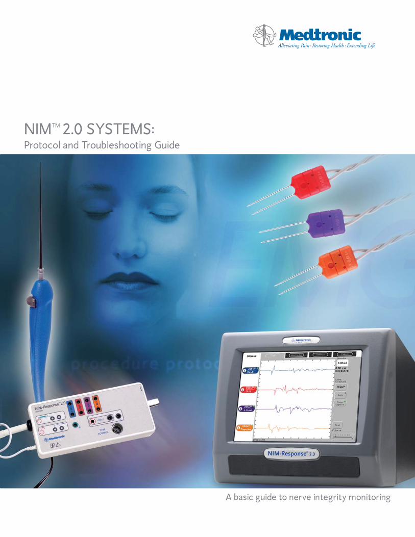
A basic guide to nerve integrity monitoring
NIM™ 2.0 SYSTEMS:Protocol and Troubleshooting Guide
W E L C O M E
Medtronic ENT has developed this basic guide to nerve integrity monitoring as it applies to the NIM™ 2.0 System family to assist in simplifying setup procedures. (TheNIM 2.0 System family includes the NIM-Response® 2.0 and the NIM-Neuro® 2.0.)
Each section gives procedure-specific protocols to follow and includes such informationas: monitoring goals, electrode placement, impedance values, difference values,threshold and stimulation ranges, as well as samples of responses.
We hope that this booklet will be a helpful guide to follow and we appreciate your patronage.
Important: This document is not intended to replace the surgeon’s medical judgment or knowledge of neural anatomy and physiology. Nerve monitoring does not prevent the surgical severance of nerves. Nerve monitoring with the NIM 2.0 System family or other monitors is only a technical aid and cannot substitute for the skill, experience and anatomical knowledge of the surgeon.
The user should refer to Medtronic ENT’s Operations Manual for further instruction regarding any equipment referenced in this document. Requisite training and know-how for performing evoked EMG monitoring in surgical applications supplements the surgeon’s knowledge of nerve anatomy for preservation of nerve function during surgical procedures.
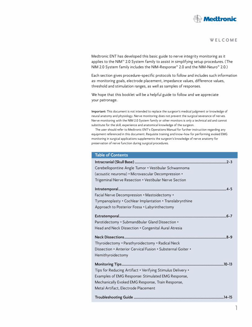
Table of ContentsIntracranial (Skull Base) ...........................................................................................................2-3Cerebellopontine Angle Tumor • Vestibular Schwannoma(acoustic neuroma) • Microvascular Decompression •Trigeminal Nerve Resection • Vestibular Nerve Section
Intratemporal..............................................................................................................................4-5Facial Nerve Decompression • Mastoidectomy •Tympanoplasty • Cochlear Implantation • TranslabrynthineApproach to Posterior Fossa • Labyrinthectomy
Extratemporal.............................................................................................................................6-7Parotidectomy • Submandibular Gland Dissection •Head and Neck Dissection • Congenital Aural Atresia
Neck Dissections.......................................................................................................................8-9Thyroidectomy • Parathyroidectomy • Radical NeckDissection • Anterior Cervical Fusion • Substernal Goiter •Hemithyroidectomy
Monitoring Tips.......................................................................................................................10-13Tips for Reducing Artifact • Verifying Stimulus Delivery •Examples of EMG Response: Stimulated EMG Response,Mechanically Evoked EMG Response, Train Response,Metal Artifact, Electrode Placement
Troubleshooting Guide .........................................................................................................14-15
1

2
Skull base procedures may place at riskthat segment of the facial nerve (CranialNerve VII) from the brainstem throughthe internal auditory canal (IAC). Tumorsmay be located either adjacent to thebrain stem or within the IAC and areoften intimately involved with the facialnerve. In order to remove the tumor,there will be considerable drilling of bonewhich may produce heat that may affectthe nerve. Nerve dissections often involve direct manipulation, stretching ortraction of the facial nerve. The facialnerve is nonmyelinated at this section,hence lesser amounts of stimulation willproduce an EMG effect.
If other cranial motor nerves are at risk,additional electrodes may be placed tomonitor EMG activity in the appropriatemuscle. Additional cranial nerves that are commonly monitored in skull baseprocedures include the trigeminal nerve(Cranial Nerve V) and the vagus nerve(Cranial Nerve X).
As a general rule, when shunting currentdirectly through bone, you will need 1.0mAof stimulus for every millimeter of boneabove the nerve. Shunting through softtissue will usually require a setting of atleast 0.8mA.
Monitoring GoalLocate, identify, and map the nerve.
Monitor manipulation effect.
It is extremely valuable for the surgeon to verify nerve integrity prior to closing bystimulating proximal to the tumor site BEFORE and AFTER the surgery.
Cerebellopontine Angle Tumor
Vestibular Schwannoma(acoustic neuroma)
Microvascular Decompression
Trigeminal Nerve Resection
Vestibular Nerve Section
I N T R A C R A N I A L ( S K U L L B A S E )
Procedures
3
I N T R A C R A N I A L ( S K U L L B A S E )
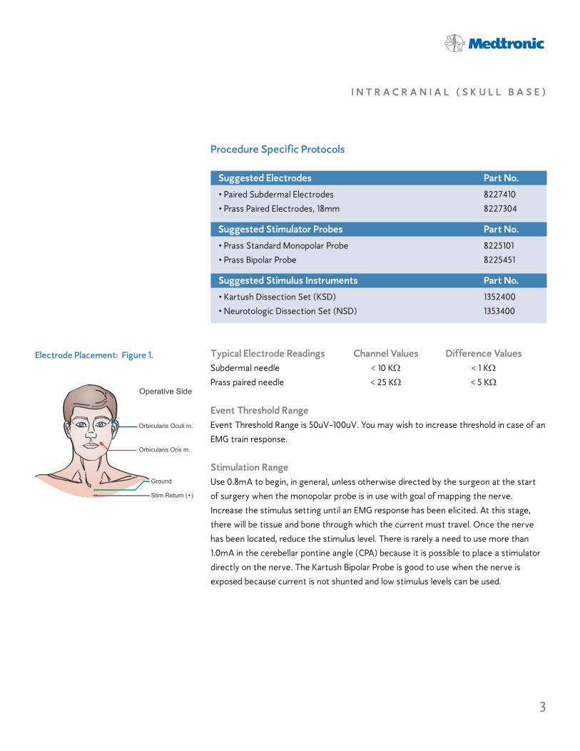
Ground
Orbicularis Oculi m.
Orbicularis Oris m.
Stim Return (+)
Operative Side
Electrode Placement: Figure 1.
Procedure Specific Protocols
Suggested Electrodes Part No.
• Paired Subdermal Electrodes 8227410• Prass Paired Electrodes, 18mm 8227304
Suggested Stimulator Probes Part No.
• Prass Standard Monopolar Probe 8225101• Prass Bipolar Probe 8225451
Suggested Stimulus Instruments Part No.
• Kartush Dissection Set (KSD) 1352400• Neurotologic Dissection Set (NSD) 1353400
Typical Electrode Readings Channel Values Difference ValuesSubdermal needle < 10 K! < 1 K!Prass paired needle < 25 K! < 5 K!
Event Threshold RangeEvent Threshold Range is 50uV-100uV. You may wish to increase threshold in case of anEMG train response.
Stimulation RangeUse 0.8mA to begin, in general, unless otherwise directed by the surgeon at the start of surgery when the monopolar probe is in use with goal of mapping the nerve. Increase the stimulus setting until an EMG response has been elicited. At this stage,there will be tissue and bone through which the current must travel. Once the nervehas been located, reduce the stimulus level. There is rarely a need to use more than1.0mA in the cerebellar pontine angle (CPA) because it is possible to place a stimulatordirectly on the nerve. The Kartush Bipolar Probe is good to use when the nerve is exposed because current is not shunted and low stimulus levels can be used.
4
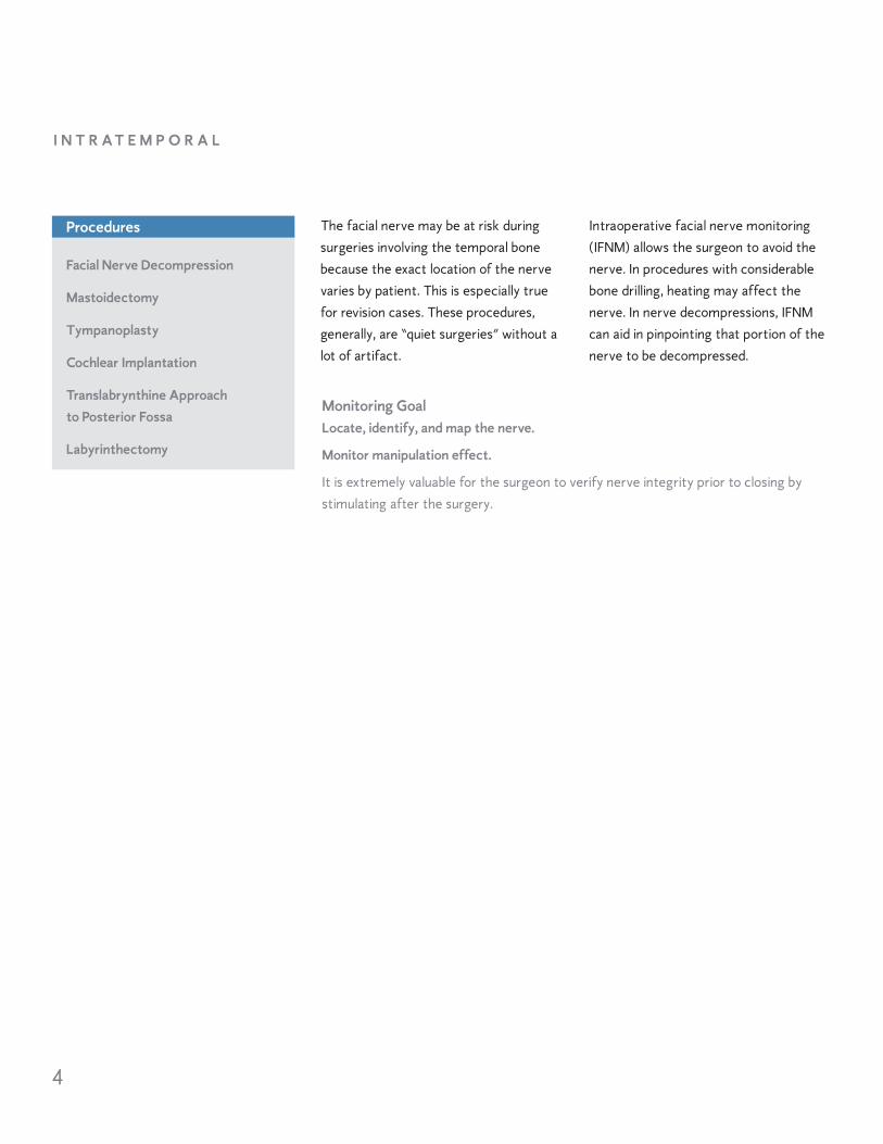
The facial nerve may be at risk duringsurgeries involving the temporal bonebecause the exact location of the nervevaries by patient. This is especially truefor revision cases. These procedures,generally, are “quiet surgeries” without alot of artifact.
Intraoperative facial nerve monitoring(IFNM) allows the surgeon to avoid thenerve. In procedures with considerablebone drilling, heating may affect thenerve. In nerve decompressions, IFNMcan aid in pinpointing that portion of thenerve to be decompressed.
Monitoring GoalLocate, identify, and map the nerve.
Monitor manipulation effect.
It is extremely valuable for the surgeon to verify nerve integrity prior to closing bystimulating after the surgery.
Facial Nerve Decompression
Mastoidectomy
Tympanoplasty
Cochlear Implantation
Translabrynthine Approach to Posterior Fossa
Labyrinthectomy
I N T R A T E M P O R A L
Procedures
5
I N T R A T E M P O R A L
Ground
Orbicularis Oculi m.
Orbicularis Oris m.
Stim Return (+)
Operative Side
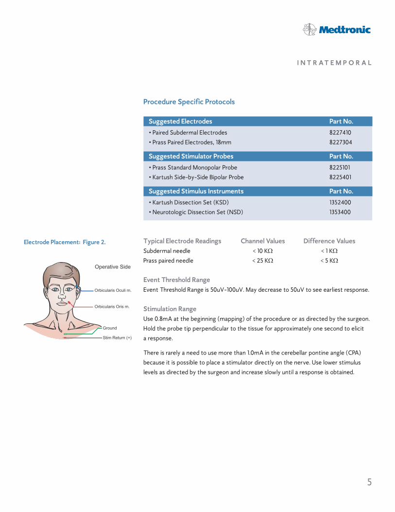
Electrode Placement: Figure 2.
Procedure Specific Protocols
Suggested Electrodes Part No.
• Paired Subdermal Electrodes 8227410• Prass Paired Electrodes, 18mm 8227304
Suggested Stimulator Probes Part No.
• Prass Standard Monopolar Probe 8225101• Kartush Side-by-Side Bipolar Probe 8225401
Suggested Stimulus Instruments Part No.
• Kartush Dissection Set (KSD) 1352400• Neurotologic Dissection Set (NSD) 1353400
Typical Electrode Readings Channel Values Difference ValuesSubdermal needle < 10 K! < 1 K!Prass paired needle < 25 K! < 5 K!
Event Threshold RangeEvent Threshold Range is 50uV-100uV. May decrease to 50uV to see earliest response.
Stimulation RangeUse 0.8mA at the beginning (mapping) of the procedure or as directed by the surgeon.Hold the probe tip perpendicular to the tissue for approximately one second to elicit a response.
There is rarely a need to use more than 1.0mA in the cerebellar pontine angle (CPA) because it is possible to place a stimulator directly on the nerve. Use lower stimuluslevels as directed by the surgeon and increase slowly until a response is obtained.
6
Most common in this group for facialnerve monitoring is the parotidectomy.The facial nerve enters the parotid glandas one bundle, then splits into five different branches within the body of theparotid gland. To monitor a given nervebranch, electrodes must be placed in themuscle that it innervates. The nerve ismyelinated now, hence more stimulus isusually necessary to evoke a response.
In general, parotidectomies are “noisysurgeries” due to potential manipulationof the nerve during blunt dissection.Also, the electrodes are in close proximity to the surgical site.
Monitoring GoalLocate, identify, and map the nerve and branches.
Monitor manipulation effect.
It is extremely valuable for the surgeon to verify nerve integrity prior to closing bystimulating proximal to the tumor site BEFORE and AFTER the surgery.
Parotidectomy
Submandibular Gland Dissection
Head and Neck Dissection
Congenital Aural Atresia
E X T R A T E M P O R A L
Procedures

7
E X T R A T E M P O R A L
Ground
Frontalis m.
Orbicularis Oculi m.
Orbicularis Oris m.
Mentalis m.
Stim Return (+)
Operative Side
Electrode Placement: Figure 3.
Procedure Specific Protocols
Suggested Electrodes Part No.
• Paired Subdermal Electrodes 8227410• Prass Paired Electrodes, 18mm 8227304
Suggested Stimulator Probes Part No.
• Prass Standard Monopolar Probe 8225101• Kartush Side-by-Side Bipolar Probe 8225401
Typical Electrode Readings Channel Values Difference ValuesSubdermal needle < 10 K! < 1 K!Prass paired needle < 25 K! < 5 K!
Event Threshold RangeEvent Threshold Range is 100uV-150uV.
Stimulation RangeUse 0.8mA at the beginning of the procedure (mapping) or as directed by the surgeon.Increase rapidly until a response is evoked. May need to increase to 3.0mA.
The best guideline for setting the stimulus intensity level is to use the lowest amountof stimulation needed to produce an EMG response large enough for monitoring. Be prepared to stimulate to as high as 3mA if necessary. Apply probe perpendicular to tissue for approximately one second to elicit a response.
8
Intraoperative monitoring of the Recurrent Laryngeal Nerve – branch ofthe Vagus (Cranial Nerve X). This surgery may be “noisy” due to potentialmanipulation of the nerve during bluntdissection. Also, the EMG tube is in closeproximity to the surgical site which mayproduce some artifact.
Tips for Monitoring during Anterior Cervical SurgeryThe EMG Endotracheal Tube should beutilized as for thyroidectomy. It may notbe possible to directly stimulate the Recurrent Laryngeal Nerve as it may not be exposed. However, the NIM 2.0System family will passively monitortraction and pressure status of the nerveand is especially helpful while theThompson Retractor is being positionedand extended.
Monitoring GoalMap the nerve, monitor manipulation effect, and verify nerve integrity.
It is extremely valuable for the surgeon to verify nerve integrity prior to moving to thecontralateral lobe dissection and prior to closing. Stimulate proximally and distally tothe tumor site.
Thyroidectomy
Parathyroidectomy
Radical Neck Dissection
Anterior Cervical Fusion
Substernal Goiter
Hemithyriodectomy
N E C K D I S S E C T I O N S
Procedures

9
N E C K D I S S E C T I O N S
MAINTAIN PATIENT’S EMG TUBE MIDLINE
Right Vocal Fold
Operative Side
Left Vocal Fold
Ground
Stim Return (+)
NIM™ StandardElectrode Placement: Figure 4b.
Procedure Specific Protocols
Suggested Electrodes Part No.
NIM™ EMG Reinforced Endotracheal Tubes 8229XXXSee catalog for choice of sizes.• Usually use one size larger than normal.• Use only non anaesthetic lubricants like K-Y® Jelly.
• Place EMG tube in the midline & with electrodes in contact with vocal cords. Secure tube to midline of mouth (not to the side). Temporarily deflate cuff foradjusting position. Complete instructions are provided in the package insert.
• Visualize electrodes contacting true vocal cords.
Suggested Stimulator Probes Part No.
• Prass Standard Monopolar Probe 8225101• Kartush Side-by-Side Bipolar Probe 8225401
Typical Electrode Readings Channel Values Difference ValuesEMG tube < 10 K! < 1 K!
Event Threshold RangeEvent Threshold Range is 100uV-150uV.
Stimulation RangeThe Stimulation Range is approximately 1.0mA. The best guideline for setting the stimulus intensity level is to use the lowest amount of stimulation needed to producean EMG response large enough for monitoring. If stimulation levels are too high, nervefibers of adjacent branches may be stimulated. Be prepared to stimulate at a higherlevel if necessary. Apply probe perpendicularly to tissue for about a second to elicit a response.
If there is no response, shunt stimulus in the area just below the Adam’s apple (cricothyroid), through the muscle. If there is response, the tube is probably too low through the vocal cords and will need to be repositioned.
MAINTAIN PATIENT’S EMG TUBE MIDLINE
Right Vocal Fold
Operative Side
Left Vocal Fold
Ground
Stim Return (+)
NIM Contact™ TubeElectrode Placement: Figure 4.
SOHAIL RAHMAN
SOHAIL RAHMAN
SOHAIL RAHMAN
Anesthesia,Take Note!!!
SOHAIL RAHMAN
SOHAIL RAHMAN
SOHAIL RAHMAN
SOHAIL RAHMAN
Technician Note
SOHAIL RAHMAN
SOHAIL RAHMAN

10
Verifying Stimulus DeliveryThe “Stimulus Tone” or “Stimulus Voice”can be heard if stimulus is flowing to thesurgical site from the probe tip. Stimulusdelivery can also be confirmed by comparing the Stimulus setting with theStimulus Measure readings (mA). Thestimulus measure reading will be found onthe top right-hand side of the screen.The value should be approximately thesame as the stimulus setting.
Tips for Reducing Artifact• Keep the NIM 2.0 Systems away from
the electrosurgical unit and other electrical equipment.
• Ensure electrode cables are not intertwined with stim anode return or with stimulator probe cable.
• Utilize a bipolar stimulating probe as soon as the nerve is exposed to minimize artifact. Current is flowing in a very small area and stim levels can be reduced accordingly. Also, dry thesurgical area before stimulating, as fluidcan shunt current. Keep bipolar tips dryto prevent shunting.
• Minimize excessive stimulating current.Each patient’s tissue conducts electrical energy differently. To decrease artifactual interference, it isbetter to establish effective levels ofstimulating current as soon as possibleto keep the current to a minimum.Begin stimulation with the lowest level,0.05mA, with the Event Threshold at
100uV. Increase stimulus intensity fairlyquickly until raw EMG sound is heard.This is the lowest level of stimulationwhich will evoke a response. Increasestimulus until an audible event tone occurs (the four-times-per-secondtone we expect to hear when stimulating the nerve). Set the stimulation to at least this value.
• Note the reading next to the amplitudeshown on the screen and adjust theEvent Threshold slightly lower than that value. This will effectively screenout unwanted artifactual EMG activity.
• As an option in head and neck dissections, you may change the Stimulus Filter on the menu. For otology and skull base procedures, verify that the artifact delay marker is set to 3.1 milliseconds.
• If necessary, owing to frequent artifactstones, disable the “Tone Audio”. Youmust now rely on raw EMG only.
M O N I T O R I N G T I P S
11
M O N I T O R I N G T I P S
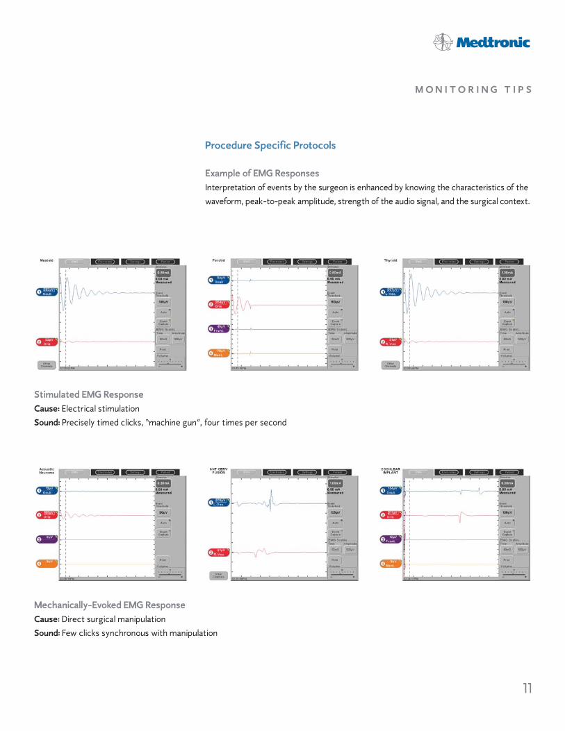
Procedure Specific Protocols
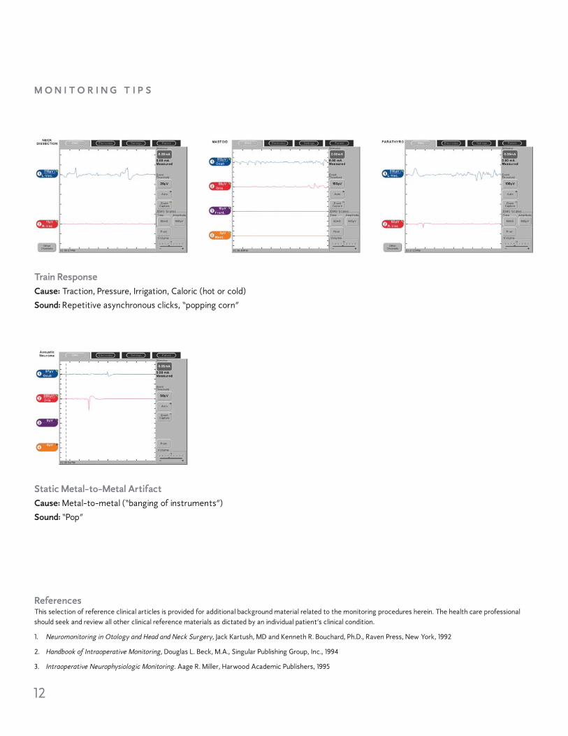
Example of EMG ResponsesInterpretation of events by the surgeon is enhanced by knowing the characteristics of thewaveform, peak-to-peak amplitude, strength of the audio signal, and the surgical context.
Stimulated EMG ResponseCause: Electrical stimulation Sound: Precisely timed clicks, “machine gun”, four times per second
Mechanically-Evoked EMG ResponseCause: Direct surgical manipulation Sound: Few clicks synchronous with manipulation
12
M O N I T O R I N G T I P S
Train ResponseCause: Traction, Pressure, Irrigation, Caloric (hot or cold) Sound: Repetitive asynchronous clicks, “popping corn”
Static Metal-to-Metal ArtifactCause: Metal-to-metal (“banging of instruments”) Sound: “Pop”
ReferencesThis selection of reference clinical articles is provided for additional background material related to the monitoring procedures herein. The health care professionalshould seek and review all other clinical reference materials as dictated by an individual patient’s clinical condition.
1. Neuromonitoring in Otology and Head and Neck Surgery, Jack Kartush, MD and Kenneth R. Bouchard, Ph.D., Raven Press, New York, 1992
2. Handbook of Intraoperative Monitoring, Douglas L. Beck, M.A., Singular Publishing Group, Inc., 1994
3. Intraoperative Neurophysiologic Monitoring. Aage R. Miller, Harwood Academic Publishers, 1995
13
M O N I T O R I N G T I P S
Ground
Orbicularis Oculi m.
Orbicularis Oris m.
Stim Return (+)
Operative Side
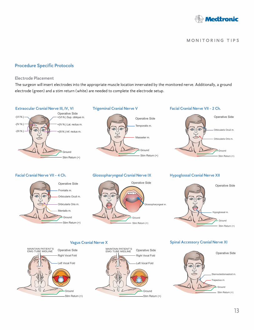
Facial Cranial Nerve VII - 2 Ch.
Ground
Frontalis m.
Orbicularis Oculi m.
Orbicularis Oris m.
Mentalis m.
Stim Return (+)
Operative Side
Facial Cranial Nerve VII - 4 Ch.
-(VI N.)
-(IV N.)
-(III N.)
+(VI N.) Sup. oblique m.
+(IV N.) Lat. rectus m.
+(III N.) Inf. rectus m.
Ground
Stim Return (+)
Operative SideExtraocular Cranial Nerve III, IV, VI
Ground
Temporalis m.
Masseter m.
Stim Return (+)
Operative Side
Trigeminal Cranial Nerve V
Ground
Stim Return (+)
Operative Side
Glossopharyngeal m.
Glossopharyngeal Cranial Nerve IX
MAINTAIN PATIENT’S EMG TUBE MIDLINE
Right Vocal Fold
Operative Side
Left Vocal Fold
Ground
Stim Return (+)
Ground
Sternocleidomastoid m.
Trapezius m.
Stim Return (+)
Operative Side
Spinal Accessory Cranial Nerve XI
Ground
Stim Return (+)
Hypoglossal m.
Operative Side
Hypoglossal Cranial Nerve XII
Procedure Specific Protocols
Electrode PlacementThe surgeon will insert electrodes into the appropriate muscle location innervated by the monitored nerve. Additionally, a groundelectrode (green) and a stim return (white) are needed to complete the electrode setup.
MAINTAIN PATIENT’S EMG TUBE MIDLINE
Right Vocal Fold
Operative Side
Left Vocal Fold
Ground
Stim Return (+)
Vagus Cranial Nerve X

Symptom Cause Solution
T R O U B L E S H O O T I N G G U I D EPlease refer to the NIM-Response® 2.0 System User’s Guide (82-50651) or the NIM-Neuro® 2.0System User’s Guide (82-50650) for complete operating instructions.
No visual display or audio alarmsat power-up.
Touching the screen has unexpected results.
Electrode impedance is too high.>10K! for subdermal electrodes>25K! for Prass Paired electrodes>10K! for EMG tube>40K! for hookwire electrodes
Electrode impedance = 0.0K!.
Channel button is flashing.Electrode reading is “— K!” or “OFF.”
Electrode difference is greaterthan 2K! (subdermal electrodes)or 10K! (Prass Paired electrodes).
Electrosurgical interference.
Interference with anesthesiaequipment.
Excessive muting.
Inadequate muting.
Power cord not connected to outlet or tothe NIM™ 2.0 system.
Power switch not turned on.
Touch screen out of calibration.
Electrode dislodged from patient, but notcompletely out.
High resistance in electrode.
Electrode pin not firmly inserted into PatientInterface.
Positive and negative electrodes touchingbelow surface of skin.
Extremely low impedance, particularly in EMGtubes.
Electrode laying on skin surface.Electrode placement insecure.
Dirty electrode tip.Electrode cable broken.
Electrode pin disconnected from Patient Interface.
Dirty electrode.Mismatched pair.Unequal placement.
Muting Probe not connected.Muting Probe input insufficient.Electrosurgical grounding inadequate.Source of interference unidentified.
NIM 2.0 system or Patient Interface cable tooclose to ESU or its cables.
Lead checking current near anesthesia elec-trodes.
Unit receiving excessive signal into the MutingProbe or electrode leads.
Signal from ESU is inadequate to cause muting.
Plug in power cord.
Turn power switch on.
Turn unit off, then press the screen until the screen calibration test is displayed. Follow the instructions on the screen to recalibrate.
Insert dislodged electrode; tape down in place.
Remove and replace with new electrode.
Check connection at Patient Interface box.
Remove and relocate electrodes.
Use “tap test” near electrodes to evoke EMG or artifact. If activity is noted on channel in question, proceed.
Re-insert electrode in question.
Remove and replace electrode in question.
Check connection to Patient Interface box.
Remove and replace electrode for appropriate channelwith highest impedance reading first.Remove and replace electrode in question.
• Check Muting Probe connections.• Move input to “MORE MUTE”.• Check electrosurgical grounding pad on patient.• Identify source of interference; then eliminate or
separate from the NIM 2.0 system.
• Maintain separation between electrosurgical cable andthe NIM 2.0 system.
• For less coupling, coil up the Muting Probe next to theNIM 2.0 system.
Have anesthesia try alternate electrode channel.Turn stimulator to 0.0mA when not stimulating.
Move the Muting Probe connector to a lower number unit until it stops muting. If it still mutes in position “1,” disconnect the muting detector completely.
Move the Muting Probe connector to a higher numberuntil it mutes. If it still does not mute in position “4,” loop the ESU cable and clip the muting detector over the doubled cable.

T R O U B L E S H O O T I N G G U I D E
No response to direct stimulation.
Unexpected responses whennot directly stimulating nerve.
Inadequate stimulus intensity.
Paralyzing anesthetic in use.
White stimulation (+) electrode has fallen outor is not connected.
Probe not connected.
Patient safety fuse blown.
Not holding probe on nerve long enough.
Nerve not contacted.
Volume control too low.Event threshold set too high.
Excessive current shunting in surgical field.
No electrodes in innervated muscle.Nerve not stimulable.
Unexplained continuous “train” EMG response.
Nerve or monitoring area being stimulatedor manipulated by thermal or mechanicalmeans.
Metal-to-metal discharge artifact.
Intertwined recording electrode andstimulator wires.
Inadvertent manipulation of electrode wires,Patient Interface cable, or recording area onpatient.
Electrical interference from other equipment.
Increase stimulus intensity.
Eliminate paralyzing anesthetic.
• Check that Stimulus Measure is approximately the same value as the Stimulus setting. Re-insert electrodein question.
• Secure all recording and stimulating electrode connections and check the impedance values.
Check stimulator anode(+) and cathode (-) connections.
Check fuse in Patient Interface box (32 mA, x 250V). Replace if necessary.
Hold probe tip to nerve for at least 1 S.
• Check stimulator tip for obstruction. Replace if necessary.
• Check location of stimulation.
Check and correct all settings: volume, event threshold,stimulus intensity.
Remove fluids from surgical stimulating area.
Place channel electrodes in muscle to be monitored.
Identify and eliminate possible source of “train”stimulation:
• Cold irrigation• Laser heat• Retraction on nerve or muscles being recorded• Patient waking from anesthesia• Nerve drying• Ultrasonic aspirator
Identify and eliminate source of inadvertentmanipulation.
Determine response type from waveform pattern on 50 mS screen.
Disentangle recording electrode and stimulator cables.
Check area near recording electrodes for excessivestretching from tape, drapes, etc.
Check for intermittent stimulation from anesthesiologist(i.e., hand-held electrical stimulator).
Move NIM 2.0 system away from source of interference.
Make sure Patient Interface cable and electrode wiresdo not cross other electrical equipment or cables.
Symptom Cause Solution
Medtronic ENTMedtronic USA, Inc.6743 Southpoint Drive NorthJacksonville, FL 32216 USAwww.MedtronicENT.comToll free: (800) 874-5797Fax: (800) 678-3995
890403 06.07 2007-341 Rev 1
This literature is intended for the exclusive use of physicians. Rx only.©2007, Medtronic, Inc. ®Registered mark of Medtronic, Inc. ™Trademark of Medtronic, Inc.K-Y® is a registered mark of Johnson & Johnson Medical, Inc.
International Telephone NumbersAustralia: 1-800-668-670Belgium: 32-2456-09-09Canada: 1-800-217-1617China: 86-21-50800998France: 33-470-679-800Germany: 49-211-5293-209Hong Kong: 852-2919-1312India: 91-22-26836733Italy: 39-02-24137-324Japan: 81-6-4795-1506
Korea: 82-2-3404-3600Lebanon: 961-1-370-670Luxembourg: 32-2456-09-09Netherlands: 31-45-566-8371Poland: 48-22-465-6942Singapore: 65-6776-6255Spain: 34-91-625-05-40UK: 44-1923-205-166USA: 1-904-296-9600
For further information, please callMedtronic ENT at 800-874-5797 or 904-296-9600. You may also consultour website at ww.MedtronicENT.com.