
88K13B07
25
TRAINING SUPPORT PACKAGE (TSP) Note: This is the TSP title page TSP Number 88K13B07 Task Number(s) Title(s) TEMPORARY HULL REPAIR Effective Date 1 OCTOBER 1997 Supersedes TSP(s) 421-113-03 1 OCTOBER 1988 TSP User SKILL LEVELLS 20, 30, 40 Proponent TRAINING DIRECTORATE ATTN: ATCL-AT 401 First Street, Suite 227 Fort Lee, VA 23801-1511 Comments/ Recommen- dations Send comments and recommendations directly to: TRAINING DIRECTORATE ATTN: ATCL-AT 401 First Street, Suite 227 Fort Lee, VA 23801-1511 Foreign Disclosure Restrictions This product has been reviewed by the product developers in coordination with the Commander, U.S. Army Combined Arms Support Command foreign disclosure authority. This product is releasable to milit ary students from foreign countries on a case-by-ca se basis.
-
Upload
lo-shun-fat -
Category
Documents
-
view
218 -
download
0
Transcript of 88K13B07

7/27/2019 88K13B07
http://slidepdf.com/reader/full/88k13b07 1/25
TRAINING SUPPORT PACKAGE (TSP)
Note: This is the TSP title page
TSP
Number
88K13B07
Task
Number(s)
Title(s)
TEMPORARY HULL REPAIR
Effective
Date
1 OCTOBER 1997
Supersedes
TSP(s)
421-113-03
1 OCTOBER 1988
TSP User SKILL LEVELLS 20, 30, 40
Proponent TRAINING DIRECTORATE
ATTN: ATCL-AT
401 First Street, Suite 227
Fort Lee, VA 23801-1511
Comments/
Recommen-
dations
Send comments and recommendations directly to:
TRAINING DIRECTORATE
ATTN: ATCL-AT401 First Street, Suite 227
Fort Lee, VA 23801-1511
Foreign
Disclosure
Restrictions
This product has been reviewed by the product developers in coordination
with the Commander, U.S. Army Combined Arms Support Command foreign
disclosure authority. This product is releasable to military students from
foreign countries on a case-by-case basis.

7/27/2019 88K13B07
http://slidepdf.com/reader/full/88k13b07 2/25
2
PREFACE
Purpose This training support package provides the instructor with a
standardized lesson plan for presenting instruction for:
TASK NUMBER: NONE
TASK TITLE: TEMPORARY HULL REPAIR
CONDITIONS: Giving class note, the evaluation plan and five questions quiz.
STANDARD: To receive a “GO” for this lesson Unit the student will answer
five questions correctly.
This TSP
contains
TABLE OF CONTENTS
Page
Preface 2
Lesson Section I - Administrative Data 3
Plan Section II - Introduction 6
Terminal Learning Objective 6
Section III - Presentation 8
A. Enabling Learning
Objective 1
11
B. Enabling Learning
Objective 2
C. (etc.)
Section IV - Summary 22
Section V - Student Evaluation 23
Appendixes A. Viewgraph Masters
B. Test and Test Solutions
C. Practical Exercises and Solutions 30
D. Student Handouts
7/27/2019 88K13B07
http://slidepdf.com/reader/full/88k13b07 3/25
3
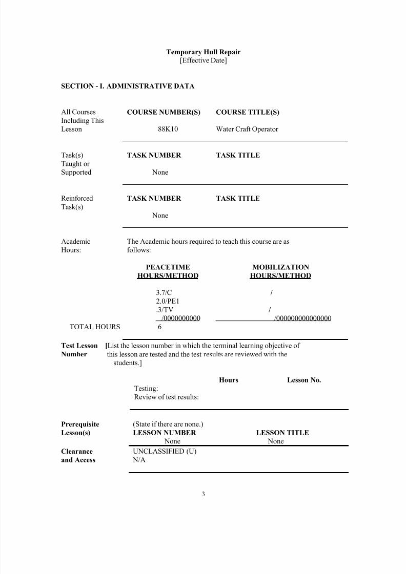
Temporary Hull Repair
[Effective Date]
SECTION - I. ADMINISTRATIVE DATA
All Courses
Including This
Lesson
COURSE NUMBER(S)
88K10
COURSE TITLE(S)
Water Craft Operator
Task(s)
Taught or
Supported
TASK NUMBER
None
TASK TITLE
ReinforcedTask(s) TASK NUMBER
None
TASK TITLE
Academic
Hours:
The Academic hours required to teach this course are as
follows:
TOTAL HOURS
PEACETIME
HOURS/METHOD
3.7/C
2.0/PE1.3/TV
/0000000000
6
MOBILIZATION
HOURS/METHOD
/
/
/000000000000000
Test Lesson [List the lesson number in which the terminal learning objective of
Number this lesson are tested and the test results are reviewed with the
students.]
Hours Lesson No.
Testing:
Review of test results:
Prerequisite
Lesson(s)
(State if there are none.)
LESSON NUMBER
None
LESSON TITLE
None
Clearance
and Access
UNCLASSIFIED (U)
N/A

7/27/2019 88K13B07
http://slidepdf.com/reader/full/88k13b07 4/25
4
References
Number Title Date Para
No.
Additional
Information
FM 55-
501-2
Haborcraft Crewman
Handbook
CH.1
0
Student Study
Assignments
See Student Packet
Instructor
Requirements
[These are special qualifications or additional requirements.]
Additional
Support
Personnel
Requirements None
Equipment
Required
Damage Control Kit
Materials
Required
Standard Classroom Materials
Classroom,
Training
Area, and
Range
Requirements
Classroom and Damage Control Facility
Ammunition
Requirements
None
Instructional
Guidance
Note: Ensure facilities, equipment, and training materials are ready
prior to class start time. Instructors will have a thorough
knowledge of reference.
Prepare by studying this lesson and identified reference
material.
Proponent
Lesson
Plan
Approvals
NAME
___________________
___________________
Rank
_____
_____
Position
__________________
__________________
Date
_______
_______

7/27/2019 88K13B07
http://slidepdf.com/reader/full/88k13b07 5/25
5
SECTION II - INTRODUCTION
Method of instruction: C
Instructor to student ratio is 1:C
Time of instruction: .2 HR
Motivator
No matter what your job or position aboard your vessel may be, you must
be able to function as a member of an emergency team member. Everyone
from the skipper to the lowest deckhand, must be able to apply the
knowledge you will gain from this block of instruction. During this period
we will instruct you in the principals of Temporary hull repair. This is
commonly called “Damage Control”. This term will be used during the
class. Both terms are more or less the same thing. A Practical Exercise
will be held at the conclusion of this block of instruction to reinforce what
you have learned.
TerminalLearning
Objective
Note: Inform the students of the following terminal learningobjective requirements.
At the completion of this lesson you [the student] will:
ACTION: Temporary Hull Repair
CONDITIONS: After this lesson the student will define the
emergency squad signal used, the compartmentation
numbering and the objectives of the DC team
STANDARD: To receive a “GO” for this lesson the student must
answer 4 of the 5 questions correctly within the timeallowed
FORCE
PROTECTION
This lesson do not require force protection
Safety
Requirements [State if there are none.]None
Risk
Assessment
Level Low
Environmental
Considerations
[State if there are none.]None
Instructional
Lead-in

7/27/2019 88K13B07
http://slidepdf.com/reader/full/88k13b07 6/25
6
SECTION III - PRESENTATION
ENABLING LEARNING OBJECTIVE
INTRODUCTION TO DAMAGE CONTROL.
Motivator: During this period we will cover the basic damage control organization
aboard a typical vessel. We will cover the emergency signals commonly used
to alert the crew. We will cover compartmentation, numbering system, and
some of the objectives of the DC team.
ACTION: After this lesson the student will define the emergency
squad, signals used, the compartmentation, numbering
and the objectives of the DC team.
CONDITIONS: Given a 5 question quiz and without reference to class
notes.
STANDARD: To receive a “GO” for this lesson the student must
answer 4 of the 5 questions correctly within the time
allowed.
Learning Step/Activity 1
[A statement describing what is to be done.]
Method of instruction: C
Instructor to student ratio is 1:C
Time of instruction: 3.2 HR
Media ______(State if there is none.)_____.
NOTE: Gain students attention, ask questions from the reading assignment or give a
pop quiz if desired.
A. Organization of the Damage Control Team Aboard Ship.
1. This team will usually consist of the following personnel (this is
“typical”).
a. Chief Engineer.
b. Engineer.
c. Bos’n.
d. Two or more seaman.
e. Engineman (two or more).
2. This DC team should have at least 90 percent of its work accomplished
before getting underway. Should an emergency occur while at sea, its too

7/27/2019 88K13B07
http://slidepdf.com/reader/full/88k13b07 7/25
7
late to provide a crossout saw to the scene if you failed to procure one while
in port.
3. Signals used for various emergencies.
a. Fire and Emergencies -
b. Abandon Ship - More than 6 short blasts and one long blast on the
whistle and the same signal on the general alarm bell.
c. Man Overboard - Hail and pass the word “Man Overboard” to the
bridge. (Hail means to shout). Indicate which side the person fell overboard.
Point to the person to help the bridge locate him.
d. Dismissal - From fire and emergency stations is 3 short blasts on
the whistle followed by the same signal on the alarm.
4. Drills are required to be held weekly.
B. Compartmentation Aboard Ship.
NOTE: Use chalkboard to describe shipboard compartmentation.
1. Horizontal division.
a. Decks are numbered from the main deck both upward and
downward.
b. Below the main deck, the numbers will increase. Example 1, 2, 3,
and so on.
c. Above the main deck, the numbers will also increase but will have
a zero preceding it. Example 01,02,03 and so on.
2. Vertical division.
a. Uses bulkheads to mark vertical boundaries.
b. Vertical and horizontal division make up compartments.
3. Numbering system.
a. First two numbers indicate which deck.
b. Second two numbers indicate the frame number where the
compartment starts (usually the forwardmost frame).
c. Single or double numbers indicate the compartments relation to

7/27/2019 88K13B07
http://slidepdf.com/reader/full/88k13b07 8/25
8
the centerline.
d. Single or double letter indicate the use of the compartment.
e. Compartment use list (partial list).
A - Storeroom.AA - Cargo storeroom.
C - Ship control.
E - Engineering space.
F - Fuel (tanks)
L - Living space.
V - Void.
W - Water (tanks)
f. Compartment 01-46-0-C would be located on the 01 deck (one
deck above the main deck) starting at frame 46, would be located on the
centerline and it is used for ship control. This is probably the wheelhouse on
an LCU.
C. Material Conditions of Readiness.
1. Three conditions of readiness.
2. Condition X-Ray.
a. Black “X” on white or metallic background. Will be on the fitting
to be closed or close to the fitting.
b. Closed at all times unless actually in use. This condition is set atall times aboard ship. It is the lowest most relaxed setting aboard.
c. Examples of this setting are the ships magazines, storerooms, and
void.
d. Can be modified.
3. Condition YOKE.
a. Black “Y” on white or metallic background. Will be on or close
to the fitting.
b. Will be set at sea in peacetime. It is also set when entering or
leaving port.
c. During wartime it will be set while in port. This provides the
second step in setting the basic battle condition.
d. This condition may be modified to meet existing conditions.
4. Condition ZEBRA.

7/27/2019 88K13B07
http://slidepdf.com/reader/full/88k13b07 9/25
9
a. This is a “RED Z” on a metallic or white background.
b. This is the third step or battle condition. This will be set for fire,
collision. General emergency and enter or leaving port in wartime.
c. Do not open an X,Y, OR Z fitting without permission from the proper authority.
d. This setting may also be modified. These fittings will have a
circle around the X,Y or Z. This means you may open the fitting to pass and
close it after you.
D. Scope of Damage Control.
1. Damage control covers both battle and non-battle damage caused by:
a. Fire.
b. Collision.
c. Grounding.
d. Explosions.
e. Loading incorrectly or too heavy a load.
2. Personnel assigned to the Emergency squad must have a good knowledge
of the vessel, its construction, characteristics, compartments, and stability.
Since you may be needed to replace one of the members of the regular squad,you must know the above items.
E. Objectives of Damage Control.
1. Prevention - Before damage control occurs, insure that watertight and
fumetight fittings are in place and working. Remove and eliminate fire
hazards. The vessels watertight integrity is what keep you floating should
you start to take on water.
2. Control of damage - Minimize and localize damage when it occurs by
control of flooding and preserving stability and bouyage. Use firefighting
procedures, patching, plugging procedures along with first aid to personnel.
3. Repair - Accomplish emergency repairs as quickly as possible.
This includes emergency power, replace structure and stability.
F. Training of Crewmembers.
We mentioned earlier who would normally be assigned to the emergency
squad. All crewmen should be trained in Damage Control procedures.

7/27/2019 88K13B07
http://slidepdf.com/reader/full/88k13b07 10/25
10
NOTE: Conduct a check on learning and summarize the learning activity.
Check-On
Learning:
Administer the attached quiz and allow five minutes for completion.
Review: Using the APC method, critique the quiz in form of an after action review.
Transition:
We will discuss the types of shoring, plugs and patches and their usage
during the next hour.

7/27/2019 88K13B07
http://slidepdf.com/reader/full/88k13b07 11/25
11
ENABLING LEARNING OBJECTIVE B
PLUGS, PATCHES, AND SHORING MATERIAL.
Motivator: During this hour we will discuss some of the first actions to take with respect
to Damage Control. We are talking about plugs, patches and shoring
material. This is usually the first action taken to control damage. This
material is made up prior to its use. This is part of the 90 percent we spoke of
earlier.
ACTION: After this lesson unit the student will state the first
actions to be taken following a damage control
situation.
CONDITIONS: Given a 5 question quiz and without class notes.
STANDARD: To receive a “GO” for this lesson, the student must
answer 4 of the 5 questions correctly within the time
allowed.
Learning Step/Activity 1
Method of instruction: C
Instructor to student ratio is 1:CTime of instruction: .9 HR
Media ______(State if there is none.) N/A_____.
NOTE: Have the damage control static display set up to demonstrate the use of plugs,
patches, and shoring. If the trainer is not available use the chalkboard to
demonstrate their uses.
NOTE: Ask frequent questions throughout the body.
A. Plugs.
1. Almost anything available can be used to plug a hole. Your ship will havea large assortment of plugs available to the repair lockers for use when
needed.
NOTE: Show an assortment of plugs and how they are used on the damage control
trainer.
NOTE: Have students turn to page 10-2 in FM 55-502-2.
2. This graph will show how much water will be admitted in an non-plugged

7/27/2019 88K13B07
http://slidepdf.com/reader/full/88k13b07 12/25
12
hole versus a partially plugged hole.
B. Patches.
NOTE: Use the D/C trainer to demonstrate the various patches.
NOTE: Demonstrate this type of patch on the DC trainer.
1. Hinged or folding plate patch. This is simply two half-circles of either
wood or metal that is hinged to allow folding a length of line is attached in
the center to provide a tie off point. “Gasket” material is used to seal the
patch. It can be used without going on the outside the ship.
2. Plate patch. Made from a length of steel plate. This plate patch is usually
spot welded to the sides of the vessel. It may be tied off with lengths of line
attached to its four corners. Gasket material (such as pillows and blankets)
may be used to seal the patch.
3. Flexible plate patch. Same as the above except the metal is lighter and
more flexible. It is used to seal the curved sides of the vessel. Strips of metal
are provided every 6 to 8 inches to provide rigidity.
4. Collision mat. Large canvas mat covered on one side with long hairlike
fibers. Used line fibers are worked into one side of the canvas. This is called
“Thrumming”. Another canvas layer is sewn to it so that the thrumming acts
as a gasket. Four lines are used to anchor the mat when in place. This should
not be used where fire may occur. It can be a fire hazard.
5. Box patch. This particular patch is used over a jagged hole that has edges
protruding inward. It is a box with one side open that is fitted over the hole.Again, some type of gasket material is used to seal the leak. It may be held in
place with either shoring or a system of hookbolts.
6. Hookbolts. This is essentially a long bolt that is threaded on one end and
the other end is shaped into either a T,J, or L shape. These bolts are provide
with washers and wingnuts to facilitate tightening with the fingers.
7. Folding T hookbolt. This is much the same except one end is free to
move. It will fasten objects at angles of less than 90 degrees.
C. Shoring and Bracing Material.
1. Clear the decks of wreckage.
2. This is a process of placing supporting beams either above, below, or
against a structure. It is used to brace a patch or to prevent sagging, metal
fatigue or bulging.
3. Good judgment is necessary when erecting shoring - if you have doubt that
a structure will hold - SHORE IT UP.

7/27/2019 88K13B07
http://slidepdf.com/reader/full/88k13b07 13/25
13
4. Some indicators are listed below to help you in the decision to shore.
a. Deep bulges in metal plating.
b. Bowed frames and stanchions.
c. Loose or missing rivets or welds and seams leaking.
d. Bulkheads “panting” (bending with the sea).
5. Shoring material.
a. We use the following types of wood for shoring.
[1] Douglas fir.
[2] Yellow pine.
[3] Spruce.
[4] Hemlock.
b. Douglas fir and Yellow pine are the primary choices of wood used
for shoring.
c. Hemlock and spruce are secondary choices for shoring use.
d. Shoring is never painted, however it may be treated with a fire
resistant chemical.
e. Shores usually are received on board in 20 feet lengths.
f. These shores are distributed about ship it in “accessible areas. If
all possible they are located above the waterline.
g. Maximum length of shores are 30 times the maximum width, for
example a 2x4 can be only 5 feet long.
D. Types of Shoring Structures.
1. Direct compression.
NOTE: Demonstrate the types of structures either on the chalkboard or utilize the DC
trainer.
a. Pressure is acting on the axis.
b. Will support a greater load of weight.
c. This type of structure will be used to secure a patch in place or to
hold a hatch shut. Strongest type because it is at a 90 degree angle.

7/27/2019 88K13B07
http://slidepdf.com/reader/full/88k13b07 14/25
14
2. Cross-axial.
a. Pressure is acting parallel to the axis.
b. This is not as strong as the Direct pressure of shoring.
c. This type of structure should be used as much as possible.
3. Triangulation.
a. Both shores are under direct compression.
b. Ends are cut with a combination of degrees that equal 90.
c. Install at angles of less than 90 degrees.
E. Wedges.
NOTE: Show an assortment of wedges to the class. Wedges provide a means of
tightening or adjusting shoring.
1. Made from the same material as the shoring material. It is a triangular
block of wood. It is cut with a course saw so that the wood will soak up
water and swell. This will tighten the repair and tend to seal small holes such
as plating. The width of the wedge is fitted to the width of the shore.
2. The wedge is 5 to 6 times the thickness of the butt end, for example a 2
inch butt will mean the wedge will be 12 inches long.
3. Installing wedges.
a. Width of wedge is fitted to the width of the shore.
b. Rough cut of wedge to rough cut of the shore.
c. Use wedges in pairs. Two wedges equal a rectangle.
d. Use equally weighted hammers or mauls and drive wedges in
simultaneously.
4. Drill two small holes at each end of a small crack then seal with wedges.The small holes stop the crack from getting bigger.
5. If wedges need to be secured use a cleat.
F. Shole: This is a flat block of wood that is used to distribute pressure. It is
generally made of soft wood and is about 1 X 8 inches long. It is normally
made up on scene to fit the requirements.
G. Strongback: Quite simply this is used to distribute pressure or as an
7/27/2019 88K13B07
http://slidepdf.com/reader/full/88k13b07 15/25
15
anchor over a hole. It can be made from a shore or some heavy plank..
Check-On
Learning:
Administer the attached quiz and allow five minutes for completion.
Review: Using the APC method, critique the quiz in form of an after action review.
Transition: During the next hour we will describe how to measure and cut shoring to
install structure.
NOTE: Conduct a check on learning and summarize the learning activity.
ENABLING LEARNING OBJECTIVE
MEASURING AND CUTTING SHORES.
Motivator: We have covered material that will be necessary to have aboard your ship for
the control of damage. Since we could not possibly prefabricate shoring for
all instances where it could be used, it therefore stands that you must be able
to cut shoring to the correct size. During this hour we will discuss how toaccurately measure and cut shoring for repairs.
ACTION: After this lesson the student will answer questions
concerning measuring and cutting shoring.
CONDITIONS: Given a five question quiz and without class notes.
STANDARD: To receive a “GO” for this lesson the student must
answer 4 of the 5 questions correctly within the time
allocated.
1. Learning Step/Activity 1
[A statement describing what is to be done.]
Method of instruction: C
Instructor to student ratio is 1:C

7/27/2019 88K13B07
http://slidepdf.com/reader/full/88k13b07 16/25
16
Time of instruction: .1 HR
Media ______(State if there is none.)_____.
NOTE: We will start by looking at what measurements should be set up in front of
the class.
NOTE: All measuring and cutting material should be set up in front of the class.
NOTE: Gain students attention, ask questions during the conference period.
A. Using the Carpenter’s Square to Cut Shoring.
1. Use a tape measure or folding rule to measure the height of the
compartment. This measurement will be from the center of the strongback to
the deck. This is the vertical measurement.
NOTE: Use the Chalkboard to explain these steps.
2. Again using a tape or folding rule measure from the anchor point to the
bulkhead and subtract from the measurement the thickness of the strongback.
All measurements must be to the nearest 1/16 inch.
3. To find the length of the shore it is first necessary to lay off the two
measurements described above on the carpenters square. Use a scale of one
inch to one foot.
4. Lay off the vertical measurement on the “tongue” of the square and
horizontal measure on the “body”.
NOTE: Explain the “tongue” and “body” of the Carpenter’s square.
5. From these two marks on the square, simply measure the diagonal line
between the two for the length of the shore.
NOTE: Have students turn to table found in handout 421-301.
6. Place the carpenter’s square on the shore to be out. Align the square with
the top of the shore and the vertical and horizontal measurements marked on
the square. Mark the end of shore and cut.
7. After this cut, mark the center of stock. Lay the carpenter’s square on thecut side and mark a 90 degree angle from the center of stock.
8. One end of the shore is now is ready for use.
9. Measure for the length of the shore along the center of stock. Reverse the
angles on the square for this end.
10. Your shore is now cut to fit a specific location.

7/27/2019 88K13B07
http://slidepdf.com/reader/full/88k13b07 17/25
17
11. Cutting is usually done with a handsaw circular saw or chisel, axes,
hatchets or a chain saw.
B. Using the Shoring Batten.
1. After the preceding discussion concerning measurement and cutting of
shores, I’m sure you will be pleasantly surprised *** to find that the shoring batten is much more accurate and provides very quick results.
NOTE: Have shoring batten ready for demonstration.
2. It consists of two lengths of wood joined by a strip of metal and secured
with a wing nut.
3. A 90 degree angle is located on each end which is secured by a wing nut.
When this nut is not secured the angle will rotate.
4. This device is NOT in the supply system. Units must fabricate the shoring
batten from material available on the ship.
5. In use, the device is placed against the anchor point, unlocked and
extended to the strongback. It is looked again, and handed out to the person
cutting the shore. He lays the batten on the shore, subtracts a half inch for
wedges , marks and cuts the lumber.
6. Each vessel should have several of these handy devices available in
several locations.
C. Trimming Shores.
1. Shoring should be trimmed so that chipping and splitting do not occur.
2. The ends of shores should not have a sharp point. When subjected to
heavy pressure the shore will tend to slip, curl, or work loose in moderate
seas.
3. Shoring that is subjected to very heavy compression should have the ends
cut at a 90 degree angle.
4. To increase holding power, sockets may be cut into other shores.
D. Types of Pipe Patching.
1. Thumb and C-clamp - Uses a block of soft wood that has been roughly
shaped to fit the pipe and held in place with either a thumb or C-clamp.
2. Soft patch - Use a soft wood plug or a wedge to drive in the split, cut in
off, then use gasket material to seal the area off. You may then wrap the
outside with either marline, or other suitable material.
3. Jubilee patch - Uses a prefabricated cylinder or metal with flanges and
7/27/2019 88K13B07
http://slidepdf.com/reader/full/88k13b07 18/25
18
holes in pipe. Wing nuts are provided to anchor the patch. Gasket material
may be used to patch high pressure lines that have been damaged. A mix of
liquid resin and hardening agent is smeared over fibrous glass material.
NOTE: Conduct a check on learning and summarize the learning activity.
Check-On
Learning:
Administer a five question quiz and allow 5 minutes to complete.
Review: Using the APC method, critique the quiz in form of an after action review.
Transition: During the next hour we will discuss the use of the dewatering pump aboard
ship and how it is used.

7/27/2019 88K13B07
http://slidepdf.com/reader/full/88k13b07 19/25
19
ENABLING LEARNING OBJECTIVE
DEWATERING PUMPS.
Motivator: During the preceding 3 hours we have followed a sequence of events from theinitial call for the emergency team to various types of ways to “fix” the
problem. One problem now remains for us to complete, repairs. The vessel
has several ways to remove water. You should have a general idea of the
systems used aboard ship for this purpose.
ACTION: After this lesson unit the student will identify the
systems used for dewatering a vessel.
CONDITIONS: Given a 5 question quiz and without class notes.
STANDARD: To receive a “GO” for this lesson the student must
answer 4 of the 5 questions correctly within the time
allowed.
1. Learning Step/Activity 1
[A statement describing what is to be done.]
Method of instruction: C/TV
Instructor to student ratio is 1:C
Time of instruction: 1.0 HR
Media ______(State if there is none.)_____.
NOTE: We will begin by discussing the drainage system aboard ship.
NOTE: Gain students attention, ask questions throughout the lesson.
A. Drainage Systems (without pumps).
1. Plumbing and deck drains.
a. Very simple drainage system which used gravity to drain some
compartments. Normally the extreme forward and after compartment.
b. This system is found mostly above the waterline and on the
weather decks.
c. A danger may exist with this type of system because it could back
up and flood the compartment.
2. Main drainage system.
a. Serves the machinery spaces such as the engine room.

7/27/2019 88K13B07
http://slidepdf.com/reader/full/88k13b07 20/25
20
b. Larger ships will have secondary systems for auxiliary spaces.
c. This system has its own eductor to pump waste over the side.
d. Smaller vessels will have a primary system only.
e. The overboard discharge connection is located on the port and
starboard side to pump excess water overboard.
f. The drains are used to let water flow from forward to the primary
drainage system and then pumped over the side.
B. Types of Emergency Pumps.
1. Electric submersible pump.
a. Available in two types either AC or DC.
b. Used to pump uncontaminated fresh or salt water.
c. It may be used to pump fuel oil or JP5 for short period in an
emergency.
d. Never pump low ignition fuels or hot water, this will crack the
casing or cause an explosion.
e. These pumps are either AC or DC, and will pump a minimum of
160 gallons per minute at a 70 foot head.
2. PE-250 pump.
1. The primary purpose of the pump is for fighting fires. Its secondary
purpose is dewatering.
2. The pump is a self-priming., 250 gallon per minute, two cylinder, two
cycle 25 horsepower engine. The engine is water cooled by water being
circulated through the block. The water only circulates when the engine
without having the intake hose submerged. The intake is a 3 inch diameter,
hard rubber hose (usually black) available in 10 feet sections.
3. The discharge side is a two and one half inch outlet. This outlet will use atri-gate to accept the use of a one and half inch fire hose.
NOTE: Show film 551-0537-B and 551-0538-B “Emergency Fire Pumps Parts 1 and
2.
NOTE: Show film MN-10036/Z4978 “Seven Sailors”
NOTE: Conduct a check on learning and summarize the learning activity.

7/27/2019 88K13B07
http://slidepdf.com/reader/full/88k13b07 21/25
21
Check-On
Learning
Administer a 5 question quiz and allow 5 minutes to complete.
Review: Critique the quiz using the APC method in the form of an after action review.
The remaining time will be used to practice what you have learned. The
Damage Control Trainer located behind Building 2716-K* will be used for this training.

7/27/2019 88K13B07
http://slidepdf.com/reader/full/88k13b07 22/25
22
SECTION IV - SUMMARY
Method of instruction: C
Instructor to student ratio is 1:C
Time of instruction: .2 HR
Review/
Summarize
Lesson
Review last 4 hours.
Check on
Learning
Determine if students have learned the material presented by --
a. Soliciting questions and explanations.
b. Asking questions and getting answers from the students.
c. Correcting student misunderstandings.
Transition
To Next
Lesson
[If applicable]

7/27/2019 88K13B07
http://slidepdf.com/reader/full/88k13b07 23/25
23
SECTION V - STUDENT EVALUATION
Testing
Requirements
Describe how the student must demonstrate accomplishment of the
TLO.
The information contained in this lesson plan will be tested on IBM
Examination 9G8-105-02.
NOTE: Refer student to the Student Evaluation Plan
Feedback
Requirement
a. Schedule and provide feedback on the evaluation and any
information to help answer students’ questions about the test.
b. Provide remedial training as needed.
NOTE: Rapid, immediate feedback is essential to effective learning.

7/27/2019 88K13B07
http://slidepdf.com/reader/full/88k13b07 24/25
24
PRACTICAL EXERCISE SHEET NO.
Title Temporary Hull Repair
Method of instruction: CInstructor to student ratio is 1:C
Time of instruction: 2.0 HRS
Introduction
During the next hour you will be assigned to a billet as you would be on board
ship. You will be required to react to a Damage Control situation by plugging,
patching and building structure to contain damage. You may or may not be
required to dewater the compartment.
Motivator
You will be divided into the approximate number of crew board ship. One
student will be in charge of the DC team. He/she will assign responsibilities to
the remainder of their crew.
Terminal
Learning
Objective
Note: Inform the students of the following terminal learning
objective requirements.
At the completion of this lesson you [the student] will:
ACTION: During the Practical Exercise the student will supervise
emergency patching, shoring and dewatering operations
under simulated shipboard conditions.
CONDITIONS: Given a Damage Control trainer, all necessary tools,
equipment, lumber, patching material, dewatering pump, and hoses.
STANDARD: To receive a “GO” for this exercise the student must
control the inflow of water with the material provided.
The exercise is considered to be successful if the water
does not reach the lower level of the porthole, or water
is being pumped out.
Safety
Require-ments
Read safety statement to assembled students. Statement is contained
elsewhere in this lesson plan.
Risk
Assessment
Level
Medium
Environmental
Considerations
[State if there are none.]

7/27/2019 88K13B07
http://slidepdf.com/reader/full/88k13b07 25/25
NOTE: Depending on size of class, divide students into groups similar to the size
of an Emergency Squad aboard ship.
Instructional
Lead-in
NOTE: The following items will be done prior to commencing the exercise:
1. The Assistant Instructor (AI) will coordinate with the Engineering
Committee to arrange for pumps, lumber, tools, and equipment needed to
conduct the PE.
2. Students will arrange the material so that it is accessible to the scene
but away from overflow from the trainer.
3. Designate one student to act as the senior person. He will designate
the team members duties. The Senior member should not be the highestranking student.
4. Designate one person to stand by the fire hydrant for emergency shut-
down if necessary.
5. Any of the following conditions shall indicate a termination of the
exercise:
a. Water over the lower edge of the porthole glass.
b. Report of a student slipping, tripping, or falling inside the
trainer with or without water present.
c. Inclement weather as designated by current directives.
Resource
Requirements Damage control Facility
Special
Instructions
Procedures 1.
2.
Review: Critique the PE. After use have the students restore the area around the
trainer and police up the area.
Feedback
Requirements


