878-TOOL DESIGN AND DRAWING
17
878-TOOL DESIGN AND DRAWING PART -A 1. (a)design and draw the following views of the piercing die for the component given (i) Sectional elevation (ii) plan Material: mild steel sheet thickness3mm, shear strength 385.5N/mm 2 Given data- no thickness was given, refer question paper Thickness = 3 mm Material =MILD STEEL Shear strength = 385.5 N/mm 2 1. Calculation of cutting force and press capacity required:- Cutting force = S.P.T Where S = shear strength of the material in N/mm 2 P = perimeter of the blank in mm T = thickness of the sheet metal in mm For MILD steel, shear strength in385.5N/mm 2 Perimeter of the hole Ø20= 62.8mm = S.P.T = 385.5 × 62.8×3 F = 72628.2 N =7405.75Kg =7.4 ton
Transcript of 878-TOOL DESIGN AND DRAWING

878-TOOL DESIGN AND DRAWING
PART -A
1. (a)design and draw the following views of the piercing die for the component given
(i) Sectional elevation (ii) planMaterial: mild steel sheet thickness3mm, shear strength 385.5N/mm2
Given data- no thickness was given, refer question paper
Thickness = 3 mm
Material =MILD STEEL
Shear strength = 385.5 N/mm2
1. Calculation of cutting force and press capacity required:-
Cutting force = S.P.T Where S = shear strength of the material in N/mm2
P = perimeter of the blank in mm T = thickness of the sheet metal in mmFor MILD steel, shear strength in385.5N/mm2
Perimeter of the hole Ø20= 62.8mm = S.P.T = 385.5 × 62.8×3 F = 72628.2 N
=7405.75Kg=7.4 ton

2. Press capacity:-
= 1.3 × cutting force 1.3=factor of safety = 1.3 × 72628.2N
= 94416.66N =9627.476KG =9.627TONSFrom TDDB table 3.31 the press capacity required is selected as 10TONS. In mechanical press3. Design of die plate:-
Thickness of die plate = T = ∛ܨ
Where F = cutting force in KG
= T = ∛9627.476 = 21.273mm SAY 22mmThe opening to edge distance = H = 1.5t to 2tAssuming H = 1.5t = 1.5×22 = 33mmThe width of die plate = 33+40+33 = 106mmThe length of die plate = 33+40+33 = 106mmThe die size= 106x106x22mm The die land from TDDB The die land is assumed as 5mmFrom TDDB table no 3.5 angular clearances is selected as 1/20
From TDDB table 3.33 assuming long run, the material selected is (A2) steelThe die plate should be hardened and tempered to 60 HRC
4. Design of PIERCING punch:-
For piercing operation, punch governs the size of the hole; hence clearance is given on die
Clearance per side = C×T √߬max/10
= 0.01×0.5 √385.5/10 = 0.031mmFor piercing operation, PUNCH governs the size of the component and hence clearance is given on DIEThe size of the piercing punch is taken from TDDB DATA TABLE 3.9
Punch material:-
- Air hardened steel A2 is selected - The punch is hardened and tempered to 58 to 60 HRC
5. Deign of Punch holder plate:-
Equal to die block size 106X106X220mm
Material OHNS hardness 45-50HRC
6. Design of Back up plate
Thickness of thrust plate is assumed as 6mmThe size of thrust plate (length & width) is name as punch holder plate
Material:-
C45 steel hardened & tempered to 55HRC
7. Design of Stripper:-
Assuming fixed stripper (channel stripper)From table 3.7 in TDDB for plate thickness is selected as 12mm Width and length of stripper is assumed same as die plate size Moving stripper or spring stripper also be used for this part.
Material:-
Mild steel, case hardened to 55HRC Width of case depth = 0.1mm
8. Selection of die set:-
1) Assuming side feeding, since thickness this is a tool having a small die space of 106x106mmRear pillar die set is selected
2) The size of rear pillar die set are selected from TDDB table 3.25 L = 200mm W = 205mm T = 30mm P.D = 28mmFrom table 3.23 pillar bush dimensions are selected D2 = 28mm D3 = 54mm D4 = 46mm L1 = 30mm L = 80mm

9. Selection of fasteners:-
Fasteners are selected based on stripping force Stripping force = 10% of cutting force = 10/100 ×94416.66N = 9441NFrom table no 3.24 from TDDB for stripping force of 9441N M10x2 or M12x2 socket head screws are selected and dowel size 10 OR 12mm dia (2nos) of bottom half and (2nos) of top half are selected .
10. Selection of stop pinFor this component part is located by stripper plate in the case of fixed stripper, part is located by locating plate in the case of using spring loaded or moving stripper, two or more stop pin may be used for location of the component on die plate.


BILL OF MATERIALSSI.NO PART NAME MATERIAL QUANTITY
1 TOP PLATE MS 12 BACK UP PLATE OHNS 13 PUNCH HOLDER OHNS 14 PIERCING PUNCH HCHCR 25 STRIPPER PLATE OHNS 16 DIE PLATE HCHCR 17 BOTTOM PLATE MS 18 GUIDE PILLAR EN8 29 GUIDE BUSH EN8 210 ALLEN SCREW STD 411 DOWELL PIN STD 4
NOTE: This piercing tool may designed with fixed stripper or moving stripper plate, the size H,L,W may change according to the design calculation done by the studentCALCULATION-10 MARKSCOMPONENT DRAWING&BOM-5MARKSSECTIONAL ELEVATION-20 MARKSPLAN-15 MARKS

(b)Design and draw the following views of a milling fixture for the given component, take component material as steel
(I) Sectional elevation.(II) Plan
SELECTION OF fixture1. Study of the component2. Select suitable fixture3. Design the elements as per design data4. Draw the assembly drawing
FOR THIS COMPONENT STRING MILLING FIXTURE OR STRADDLE MILLING FIXTURE ARE TO BE SELECTED AND DESIGNED, THE DESIGN MAY BE FOR SINGLE PART OR GROUP.
Locating elementsSelect suitable locators to locate the work pieces according to their profile. The locator must arrest maximum degree of freedom.Here we select v locating blocks to locate and hold the component.Clamping elementsSelect suitable clamps to hold the work piece. The Clamp does not distort the surface of the work piece and not to interfere the machining operation.Here we select one screw clamp to clamp the entire component by string Cutter setting elementsThe element is placed with reference to the cutter position that the cutter
can be moved through the cutter setting block the required machining is done on the work piece accurately.Tennon blocksTennon blocks must be placed in the fixture that provides easy location of the fixture on the machine table

BILL OF MATERIALSSI.NO PART NAME MATERIAL QUANTITY
1 BASE PLATE MS 12 WALL PLATE MS 23 FIXED PLATE OHNS 14 MOVING V BLOCK OHNS 35 FIXED V BLOCK OHNS 16 SETTING BLOCK OHNS 17 CLAMPING BOLT STD 18 TENNON BLOCK EN8 29 COMPONENT STEEL 310 ALLEN SCREWS STD 10
FIXTURE Selection-10marks, sectional elevation 20marks,
Component drawing &BOM- 10marks, plan-10marks

PART-B
(a) Design and draw a plain plug gauge as per IS6244 to inspect a hole of dia 35 H7.
Calculation 10 marks, drawing with side view 15 marks
Plug gauge 35H7
Find out the upper limit and lower limit of the gauge members
Upper limit=35+0.025= 35.025mmLower limit= 35+0.000=35.000mm
Refer IS 3455 and find out the formula for go and no go gauges.
Wear limit= K-yNo go= G±H/2
Go= (k + z) ±H/2
From IS 3455 selecting the values of gauge tolerance and wear limit corresponding to H7 tolerance grade.
H/2= 2µ= 0.002mmY= 3µ= 0.003mmZ= 3.5µ=0.035mm
Apply the values and calculate the values into the formula
Wear limit= (k-y) = 35-0.003= 34.997mmNo go= G±H/2= 35.025±0.002
Go= (k + z) ±H/2= (35.00+ 0.035) ±0.002= 35.035±0.002
Select the all other dimensions of the gauge members by using standards
Go no goL1= 60mm L1= 55mmL2= 20mm L2= 15mmL3= 25mm L3=25mmR= 4mm R=4mmD2=16mm d2= 16mmS= 1.5mm s= 1.5mm Handle no= 7
Note:- 1. For this question the IS Standard given is not suitable for given gauge size hence there is a possibility of students not able to get required date from the asked standard. The matter has been informed to Chairman, Board of Examination and suitable instructions will be given from DOTE. Please follow those instructions. (From TA (Mechanical)).
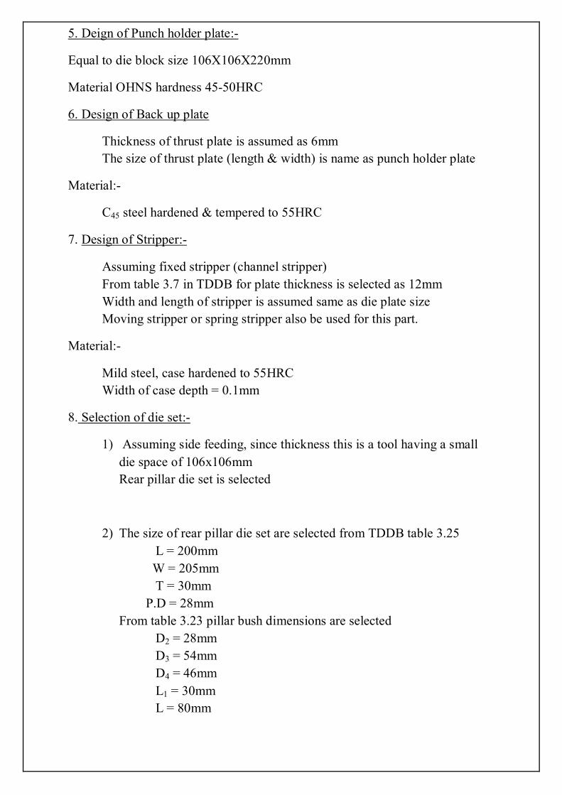
Select handle dimensions from IS 5388
D1=16±0.01 mmD2= 15.3 mmD3= 11mmL=90 mmL1= 28mme=25mms=22mm Select suitable gauge materials and handle materialsHandle materials are selected light materials for example aluminium or plastics are selected.
Gauge materials should be made by wear resistance steel.
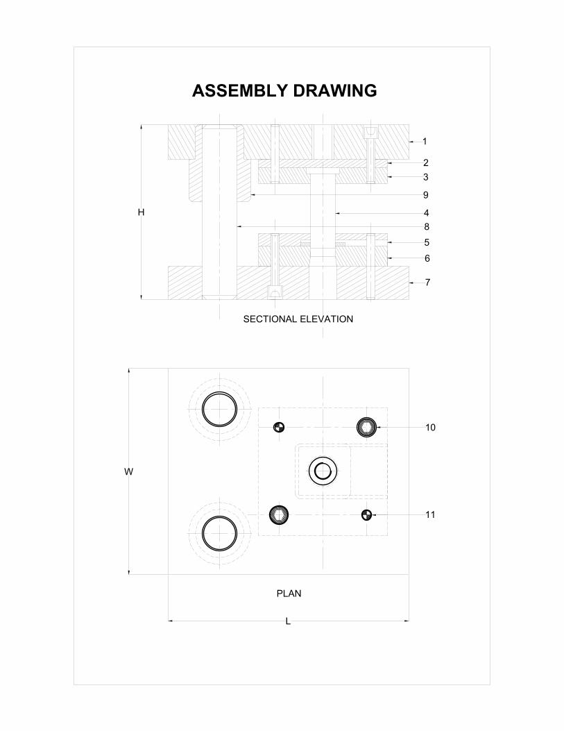
(b)Design and draw a snap gauge as per IS 3477 to inspect shafts of dia75P6
Calculation10marks, drawing with side view 15 marks
Find out the upper limit and lower limit of the gauge members
Upper limit = 75+0.051 = 75.051 mm
Lower limit = 75+0.032 = 75.032 mm
Refer IS 3455 and find out the formula for go and no go gauges.
Wear limit = G+y1
No go= G±H/2
Go = G-Z1±H/2
From IS 3455 selecting the values of gauge tolerance and wear limit
corresponding to P6 tolerance grade.
H/2=2.5µm

Y1=3µm
Z1=4µm
Wear limit=75.051+0.003
=75.054mm
GO size =75.051-0.004
=75.047±0.0025mmNOGO size =75.032±0.002
Select the all other dimensions of the gauge members using standards from gauge design date book
As per IS 3477 Blank NO 13 is selected for this snap gauge
Prepared by
N.SRINIVASAN,
LECTURER/PT,
413,INSTITUTE OF TOOL ENGINEERING,
DINDIGUL
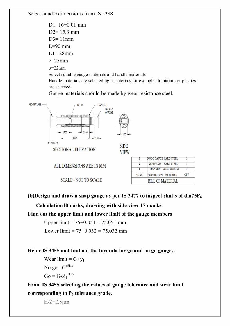
ASSEMBLY DRAWING
SECTIONAL ELEVATION
PLAN
1
2
3
4
5
6
7
H
L
W
9
8
10
11

ASSEMBLY DRAWING
SECTIONAL ELEVATION
PLAN
1
2
3
4
5
6
7
H
L
W
9
8
10
11
PIERCING DIE WITH MOVING OR SPRING LOADED STRIPPER

1
2
3
45
6
7
8
9
10
BILL OF MATERIALS
SI NO PART NAME MATERIAL
QUANTITY
1 BASE PLATE MILD STEEL 1
2 SUPPORT PLATE MILD STEEL 2
3
FIXED PLATE OHNS 1
4
MOVING V BLOCKS OHNS 3
5 FIXED V BLOCK OHNS 1
6 SETTING BLOCK OHNS 1
7 CLAMPING SCREW STEEL 1
8 TENNON BLOCKS STEEL 2
9 COMPONENT STEEL 3
10 ALLEN SCREWS STD 12
MILLING FIXTURE
COMPONENT DRAWING
8.0
30.0
42.0
22.0
Ø16.0
Ø32.0

ELEVATION SIDE VIEW
Ø 3 5 . 0 0 2 5 ± 0 . 0 0 2 Ø 3 5 . 0 0 3 5 ± 0 . 0 0 2
BILL OF MATERIAL
SI,NOPART NAME MATERIAL QUANTITY
1 HANDLE WR.AL 1
2 GO GAUGE STEEL 1
3 NO GO GAUGE STEEL 1
DIMENSIONS
GO GAUGE Ø 7 5 . 0 4 7 ± 0 . 0 0 2 5
NO GO GAUGE Ø 7 5 . 0 3 2 ± 0 . 0 0 2 5
157
13
4
15
GO
NOGO