Effective 60 Second BNI Presentations - Mike Darnell, BNI United Bangkok

BNI PBS-502-001-Z001
IP67 module, Profibus IO-Link Master
Short Guide

Balluff Network Interface Profibus, BNI PBS-502-001-Z001
1 Notes for the User 1.1 About this guide 2 1.2 Structure of the guide 2 1.3 Typografical conventions 2 1.3.1 Enumerations 2 1.3.2 Actions 2 1.3.3 Syntax 2 1.3.4 Cross references 2 1.4 Symbols 2 1.5 Abbreviations 2
2 Safety 2.1 Intended use 3 2.2 General safety notes 3 2.3 Meaning and warnings 3
3 Getting started 3.1 Connection overview, BNI PBS-502-001-Z001 4 3.2 Mechanical connection 5 3.3 Electrical connection 5 3.3.1 Supply voltage 5 3.3.2 Profibus interface 6 3.4 Connecting sensoren / actuators 7 3.4.1 Standard I/O ports 7 3.4.2 IO-Link port 7
4 Technical data 4.1 Dimensions 8 4.2 Mechanical data 8 4.3 Electrical data 8 4.4 Operating conditions 8 4.5 Function indicators 9
5 Included material 5.1 Included material 10
6 Appendix
Ordercode / order information 10
Balluff Network Interface Profibus, BNI PBS-502-001-Z001
www.balluff.com 2
1 Notes for the user
1.1 About this guide The BNI PBS-… serves as a decentralized input/output module for connecting to a Profibus
network with 4 implemented IO-Link interface. 1.2 Structure of the
guide The guide is organized so that the sections build on one another.
Section 2: Basic safety information.
Section 3: Getting started.
Section 4: Technical data for the device.
Section 5: Included Material.
1.3Typografical
conventions The following typographical conventions are used in this Guide.
1.3.1 Enumerations Enumerations are shown in list form with bullet points.
- Entry 1,
- Entry 2.
1.3.2 Actions Action instructions are indicated by a preceding triangle. The result of an action is indicated by an
arrow.
Action instruction 1.
Action result.
Action instruction 2.
1.3.3 Syntax Numbers:
Decimal numbers are shown without additional indicators (e.g. 123).
Hexadecimal numbers are shown with the additional indicator hex (e.g. 00hex).
1.3.4 Cross references Cross references indicate where additional information on the topic can be found (see
section 4 „Technical Data”).
1.4 Symbols Note Tip!
This symbol indicates general notes.
Note!
This symbol indicates a security notice which most be observed.
1.5 Abbreviations O-Port
BCD BNI EMV I-Port FE GSD-Datei LSB MSB SELV PLC PELV
Profibus DP
Digital output port Binär coded switch Balluff Network Interface Elektromagnetische Verträglichkeit Digital input port Functions earth Geräte-Stamm-Daten-Datei (Generic Station Description) Least Significant Bit Most Significant Bit Safety Extra Low Voltage Process logic control Protective Extra Low Voltage -
Profibus DP: Profibus dezentrale peripherie
LED 2

Balluff Network Interface Profibus, BNI PBS-502-001-Z001
www.balluff.com 3
2 Safety
2.1 Intended use The BNI PBS-… serves as a decentralized input/output module for connecting to a Profibus
network with 4 implemented IO-Link interface. 2.2 General safety
notes Installation and startup
Installation and startup are to be performed only by trained specialists. Any damage
resulting from unauthorized manipulation or improper use voids the manufacturer’s
guarantee and warranty.
The device is in accordance with EMC Class A. Such equipment may generate RF noise.
The operator must take precautionary measures accordingly.
The device must be powered only using an approved power supply (see section 4
“Technical data”). Only approved cable may be used.
Operating and testing
The operator is responsible for observing local prevailing safety regulations.
When defects and non-clearable faults in the device occur, take it out of service and secure
against unauthorized use.
Approved use in ensured only when the housing is fully installed.
2.3 Meaning of the warnings
Note!
The pictogram used with word “Caution“ warns of a possible hazardous situation affecting the health of persons or equipment damage. Ignoring these warnings can result in injury or equipment damage.
Always observe the described measures for preventing this danger.

Balluff Network Interface Profibus, BNI PBS-502-001-Z001
www.balluff.com 4
3 Getting started
3.1 Connection overview
BNI PBS-502-001..
Fig.: 3-1: BNI PBS-502-001-Z001
1 Mounting hole 2 M12 Profibus IN 3 Supply voltage Power In 4 Standard I/O Port 1 5 Standard I/O Port 3 6 Standard I/O/IO-Link Port 5 7 Standard I/O/IO-Link Port 7
8 Standard I/O/IO-Link Port 6
9 Standard I/O/IO-Link Port 4
10 Symbol „IO-Link-capable port”
11 Standard I/O Port 2
12 Port LEDs
13 Standard I/O Port 0 14 Status LEDs
15 Supply voltage Power Out
16 Label 17 Address switches
18 M12 Profibus OUT
19 Ground connection
1
15
2
4
5
6
7 8
16
11
12
13
3
1
9
18
19
107
17
14

Balluff Network Interface Profibus, BNI PBS-502-001-Z001
www.balluff.com 5
3 Getting started
3.2 Mechanical Connection
The module is attached using 2 M6 screws and 2 washers.
Note Tip! Recommended drill dimension: 210.5 ±0.2 mm (using 2 M6 screws!).
Note:
With this drill dimension all IP67 Profibus/Profinet modules can be mounted. 3.3 Electrical Connection
3.3.1 Supply voltage Power supply Power IN (7/8”, male) Power OUT (7/8”, female)
Pin Function Description
1 0 V 0V
2 0 V 0V
3 FE FE
4 +24 V DC Sensor/Bus communication
supply
5 +24 V DC Actuator supply
Connection
IO Module 24 V DC.
Provide sensor/bus power and actuator power from separate power sources if
possible.
Total current < 9A. The total current of all modules may not exceed 9A even when
daisy chaining the actuator supply.
Note!
The use of a Profibus hybrid cable is not allowed.
Function ground
Note Tip!
The FE connection from the housing to the machine must be low-impedance and kept as short as possible.
Balluff Network Interface Profibus, BNI PBS-502-001-Z001
www.balluff.com 6
3 Getting started
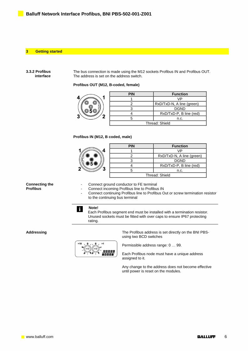
3.3.2 Profibus
interface The bus connection is made using the M12 sockets Profibus IN and Profibus OUT.
The address is set on the address switch.
Profibus OUT (M12, B-coded, female)
PIN Function
1 VP
2 RxD/TxD-N, A line (green)
3 DGND
4 RxD/TxD-P, B line (red)
5 n.c.
Thread: Shield
Profibus IN (M12, B coded, male)
PIN Function
1 VP
2 RxD/TxD-N, A line (green)
3 DGND
4 RxD/TxD-P, B line (red)
5 n.c.
Thread: Shield
Connecting the Profibus
- Connect ground conductor to FE terminal - Connect incoming Profibus line to Profibus IN
- Connect continuing Profibus line to Profibus Out or screw termination resistor
to the continuing bus terminal
Note!
Each Profibus segment end must be installed with a termination resistor. Unused sockets must be fitted with over caps to ensure IP67 protecting rating.
Addressing
The Profibus address is set directly on the BNI PBS- using two BCD switches Permissible address range: 0 … 99. Each Profibus node must have a unique address assigned to it. Any change to the address does not become effective until power is reset on the modules.

Balluff Network Interface Profibus, BNI PBS-502-001-Z001
www.balluff.com 7
3 Getting started
3.4 Connecting
Sensors /
Actuators
Four I/O ports are provided for connecting the actuators/sensors
3.4.1 Standard
I/O port
PIN Standard I/O-Port
M12, A coded, female
1 + 24 V, 200mA
2 Input / Output 2A
3 0 V
4 Input / Output 2A
5 FE
Note!
For the digital sensor inputs follow the input guideline per EN61131-2, type 2.
3.4.2 IO-Link port
PIN IO-Link Port
M12, A-coded, female
1 +24 V DC, 1,6A
2 Input / Output 1,6A
3 0 V
4 IO-Link /
Input / Output 1.6A
5 FE
Module Standard I/O port IO-Link port
BNI PBS-502-001-Z001 Max. 8 Max. 4
Note!
Unused I/O port socket must be fitted with cover caps to ensure IP67 protection
rating.

Balluff Network Interface Profibus, BNI PBS-502-001-Z001
www.balluff.com 8
4 Technical Data
4.1 Dimensions
4.2 Mechanical Data
Housing material Die case zinc, matt nickel plated
Fieldbus Profibus: M12, B-coded (female and male)
Supply power 5-pin, 7/8“ (male)
I/O Ports M12, A-coded (8 x female)
Enclosure rating IP67 (only when plugged-in and threaded-in)
Weight ca.: 735 g
4.3 Electrical Data Operating voltage 18 ... 30 V DC
Ripple < 1 %
Current draw without load ≤ 200 mA
Service port Balluff
4.4 Operating conditions
Operating temperature Storage temperature
-5 C … 70°C -25 C … 70°C
EMV - EN 61000-4-2/3/4/5/6 - EN 55011
- Severity level 4A/3A/4B/2A/3A - Gr. 1, Kl. A
Shock / vibration EN 60068 Teil2-6/27

Balluff Network Interface Profibus, BNI PBS-502-001-Z001
www.balluff.com 9
4 Technical Data
4.5 Function-
indicators
LED
Status LEDs LED Indicator Function
LED 1 Green, solid US power supply sensor / bus communication ok
LED 2 Green, solid UA power supply actuator ok
LED 3 Red, solid US power supply sensor / bus communication under voltage
LED 4 Red, solid UA power supply actuator under voltae
LED 5 Green, solid
Green, blinking
BUS data transmission with Master active BUS data transmission with Master inactive
LED indicators
Standard I/O ports
Each M12 Port (digital input/output) is assigned to LED’s which indicate the operating states
Indicator Port LED 1 (PIN 4)
Off Output = 0 Input = 0
Yellow Output = 1 Input = 1
Red I Output > Imax Input: SC*
Port LED 2 (PIN 2)
Off Output = 0 Input = 0 Diagnostics = 0
Yellow Output = 1 Input = 1
Red I Output > Imax Input: SC* Diagnostics = 1 or SC*
* SC= Short circuit detection on Pin 1. In this case both LEDs are red.
LED indicators
IO-Link port Each M12 Port (digital input/output/IO-Link) is assigned to LED’s which indicate the
operating states
Indicator Port LED 1 (PIN 4)
Off Output = 0 Input = 0
Yellow Output = 1 Input = 1
Green IO-Link communication
Green
blinking
IO-Link communication
error
Red I Output > Imax Input: SC*
Port LED 2 (PIN 2)
Off Output = 0 Input = 0 Diagnostics = 0
Yellow Output = 1 Input = 1
Red I Output > Imax Input: SC* Diagnostics = 1 or SC*
* SC= Short circuit detection on Pin 1. In this case both LEDs are red.

Balluff Network Interface Profibus, BNI PBS-502-001-Z001
www.balluff.com 10
5 Included material
5.1 Included material The BNI PBS … consists of the following components:
IO-block
2 blind plugs M12
Ground strap
Screw M4x6
20 labels
6 Appendix
Ordercode BNI PBS-50x-00x-Z001
Balluff Network Interface
Profibus
Functions
502 = IP 67 IO Module, 4 x IO-Link ports, 4 x Standard I/O ports
Variants
000 = Standard version
001 = Version 1.1
Mechanical version
Z001 = Die-cast zinc housing
Material: Balluff housing version
Profibus ports: 1 x M12x1 internal thread, 1x M12 external thread
Power: 1x7/8“ internal thread and 1x7/8” external thread
IO-Ports: 8 x M12 internal thread
Order information Product ordering code Order code
BNI PBS-502-001-Z001 BNI003K

Balluff Network Interface Profibus, BNI PBS-502-001-Z001
www.balluff.com 11
www.balluff.com
Balluff GmbH Schurwaldstrasse 9 73765 Neuhausen a.d.F. Germany Tel. +49 7158 173-0 Fax +49 7158 5010 [email protected]
Nr.
875 1
93 E
E
ditio
n 1
003
Subje
ct to
modific
atio
n