8/5/2019 AISC Seismic Steel Connection Design...
143
8/5/2019 AISC Seismic Steel Connection Design http://asp.civilbay.com/connect Vertical Brace Connection SCBF HSS Ver Brace-1 1/143 Sketch Vertical Brace Connection Code=AISC 360-16 LRFD
Transcript of 8/5/2019 AISC Seismic Steel Connection Design...

8/5/2019 AISC Seismic Steel Connection Design http://asp.civilbay.com/connect Vertical Brace Connection SCBF HSS Ver Brace-1
1/143
Sketch Vertical Brace Connection Code=AISC 360-16 LRFD
8/5/2019 AISC Seismic Steel Connection Design http://asp.civilbay.com/connect Vertical Brace Connection SCBF HSS Ver Brace-1
2/143

8/5/2019 AISC Seismic Steel Connection Design http://asp.civilbay.com/connect Vertical Brace Connection SCBF HSS Ver Brace-1
3/143
8/5/2019 AISC Seismic Steel Connection Design http://asp.civilbay.com/connect Vertical Brace Connection SCBF HSS Ver Brace-1
4/143
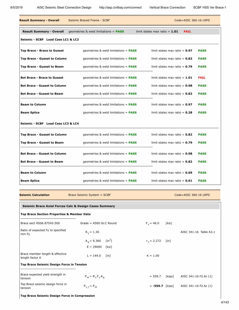
Result Summary - Overall Seismic Braced Frame - SCBF Code=AISC 360-16 LRFD
Result Summary - Overall geometries & weld limitations = PASS limit states max ratio = 1.01 FAIL
Seismic - SCBF Load Case LC1 & LC2
Top Brace - Brace to Gusset geometries & weld limitations = PASS limit states max ratio = 0.97 PASS
Top Brace - Gusset to Column geometries & weld limitations = PASS limit states max ratio = 0.82 PASS
Top Brace - Gusset to Beam geometries & weld limitations = PASS limit states max ratio = 0.79 PASS
Bot Brace - Brace to Gusset geometries & weld limitations = PASS limit states max ratio = 1.01 FAIL
Bot Brace - Gusset to Column geometries & weld limitations = PASS limit states max ratio = 0.98 PASS
Bot Brace - Gusset to Beam geometries & weld limitations = PASS limit states max ratio = 0.82 PASS
Beam to Column geometries & weld limitations = PASS limit states max ratio = 0.97 PASS
Beam Splice geometries & weld limitations = PASS limit states max ratio = 0.28 PASS
Seismic - SCBF Load Case LC3 & LC4
Top Brace - Gusset to Column geometries & weld limitations = PASS limit states max ratio = 0.82 PASS
Top Brace - Gusset to Beam geometries & weld limitations = PASS limit states max ratio = 0.79 PASS
Bot Brace - Gusset to Column geometries & weld limitations = PASS limit states max ratio = 0.98 PASS
Bot Brace - Gusset to Beam geometries & weld limitations = PASS limit states max ratio = 0.82 PASS
Beam to Column geometries & weld limitations = PASS limit states max ratio = 0.69 PASS
Beam Splice geometries & weld limitations = PASS limit states max ratio = 0.61 PASS
Seismic Calculation Brace Seismic System = SCBF Code=AISC 360-16 LRFD
Seismic Brace Axial Forces Calc & Design Cases Summary
Top Brace Section Properties & Member Data
Brace sect HSS6.875X0.500 Grade = A500 Gr.C Round F = 46.0 [ksi]
Ratio of expected Fy to specifiedmin Fy
R = 1.30 AISC 341-16 Table A3.1
A = 9.360 [in ] r = 2.272 [in]
E = 29000 [ksi]
Brace member length & effectivelength factor K
L = 144.0 [in] K = 1.00
Top Brace Seismic Design Force in Tension
Brace expected yield strength intension
P = R F A = 559.7 [kips] AISC 341-16 F2.6c (1)
Top Brace seismic design force intension
P = P = -559.7 [kips] AISC 341-16 F2.6c (1)
Top Brace Seismic Design Force in Compression
y
y
g2
y
et y y g
s_t et

8/5/2019 AISC Seismic Steel Connection Design http://asp.civilbay.com/connect Vertical Brace Connection SCBF HSS Ver Brace-1
5/143
Member length L & effective lengthfactor K
L = 144.0 [in] K = 1.00
Member radius of gyration & elasticmodulus
r = 2.272 [in] E = 29000 [ksi]
Member slenderness ratio KL/r = K x L / r = 63.37
Elastic buckling stress F = π E
( KL/r ) = 71.27 [ksi] AISC 15 Eq E3-4
when KL
r ≤ 4.71 (
E
R F ) = 103.72 AISC 15 E3
Critical stress F = 0.658 R F = 42.09 [ksi] AISC 15 Eq E3-2
Brace expected yield strength incompression
P = min ( R F A , 1.14 F A ) = 449.1 [kips] AISC 341-16 F2.3
Brace force in compression P = from user input in load section = 0.0 [kips]
Top Brace seismic design force incompression
P = P = 449.1 [kips] AISC 341-16 F2.6c (2)
Top Brace seismic design force incompression - post-buckling
P = 0.3 x P = 134.7 [kips] AISC 341-16 F2.3 (ii)
Bot Brace Section Properties & Member Data
Brace sect HSS7.500X0.500 Grade = A500 Gr.C Round F = 46.0 [ksi]
Ratio of expected Fy to specifiedmin Fy
R = 1.30 AISC 341-16 Table A3.1
A = 10.300 [in ] r = 2.493 [in]
E = 29000 [ksi]
Brace member length & effectivelength factor K
L = 144.0 [in] K = 1.00
Bot Brace Seismic Design Force in Tension
Brace expected yield strength intension
P = R F A = 615.9 [kips] AISC 341-16 F2.6c (1)
Bot Brace seismic design force intension
P = P = -615.9 [kips] AISC 341-16 F2.6c (1)
Bot Brace Seismic Design Force in Compression
Member length L & effective lengthfactor K
L = 144.0 [in] K = 1.00
Member radius of gyration & elasticmodulus
r = 2.493 [in] E = 29000 [ksi]
Member slenderness ratio KL/r = K x L / r = 57.77
Elastic buckling stress F = π E
( KL/r ) = 85.76 [ksi] AISC 15 Eq E3-4
when KL
r ≤ 4.71 (
E
R F ) = 103.72 AISC 15 E3
Critical stress F = 0.658 R F = 44.66 [ksi] AISC 15 Eq E3-2
Brace expected yield strength incompression
P = min ( R F A , 1.14 F A ) = 524.4 [kips] AISC 341-16 F2.3
Brace force in compression P = from user input in load section = 0.0 [kips]
e
2
2th
y y
0.5 th
cr( R F / F )y y e y y
th
ec y y g cr g
c
s_ci ec
s_cii ec
y
y
g2
y
et y y g
s_t et
e
2
2th
y y
0.5 th
cr( R F / F )y y e y y
th
ec y y g cr g
c
8/5/2019 AISC Seismic Steel Connection Design http://asp.civilbay.com/connect Vertical Brace Connection SCBF HSS Ver Brace-1
6/143
Bot Brace seismic design force incompression
P = P = 524.4 [kips] AISC 341-16 F2.6c (2)
Bot Brace seismic design force incompression - post-buckling
P = 0.3 x P = 157.3 [kips] AISC 341-16 F2.3 (ii)
Brace Axial Force Design Cases Summary
Refer to AISC 341-16 F2.3(i), LC1 & LC2 are the load cases in which all braces are assumed to resist forcescorresponding to their expected strength in tension P or in compression P
F2.3(ii), LC3 & LC4 are the load cases in which all braces are assumed to resist forces corresponding to theirexpected strength in tension P and all braces in compression are assumed to resist their expectedcompressive post-buckling strength P
LC1 Top Brace P =-559.7 kips (T) Bot Brace P =524.4 kips (C) AISC 341-16 F2.3(i)
LC2 Top Brace P =449.1 kips (C) Bot Brace P =-615.9 kips (T)
LC3 Top Brace P =-559.7 kips (T) Bot Brace P =157.3 kips (C) post-buckling AISC 341-16 F2.3(ii)
LC4 Top Brace P =134.7 kips (C) Bot Brace P =-615.9 kips (T) post-buckling
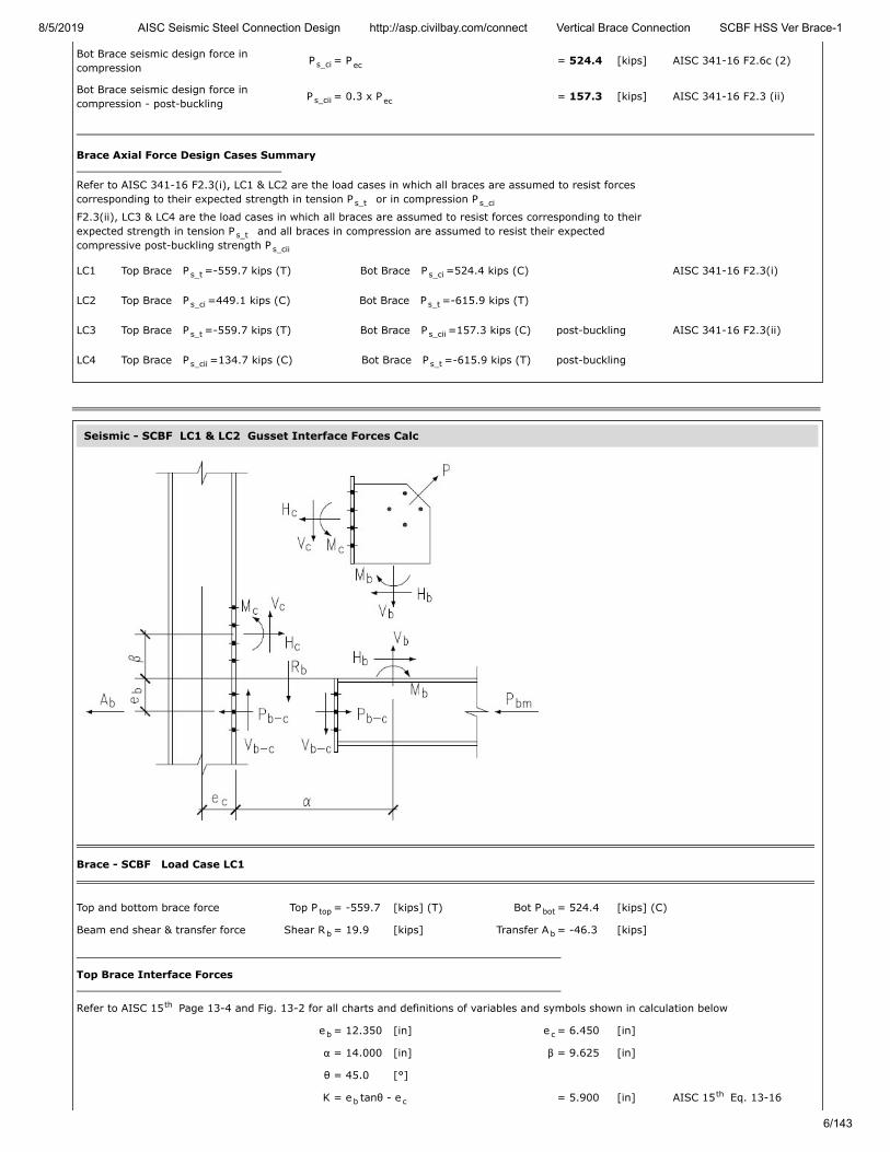
Seismic - SCBF LC1 & LC2 Gusset Interface Forces Calc
Brace - SCBF Load Case LC1
Top and bottom brace force Top P = -559.7 [kips] (T) Bot P = 524.4 [kips] (C)
Beam end shear & transfer force Shear R = 19.9 [kips] Transfer A = -46.3 [kips]
Top Brace Interface Forces
Refer to AISC 15 Page 13-4 and Fig. 13-2 for all charts and definitions of variables and symbols shown in calculation below
e = 12.350 [in] e = 6.450 [in]
α = 14.000 [in] β = 9.625 [in]
θ = 45.0 [°]
K = e tanθ - e = 5.900 [in] AISC 15 Eq. 13-16
s_ci ec
s_cii ec
s_t s_ci
s_t
s_cii
s_t s_ci
s_ci s_t
s_t s_cii
s_cii s_t
top bot
b b
th
b c
b cth
8/5/2019 AISC Seismic Steel Connection Design http://asp.civilbay.com/connect Vertical Brace Connection SCBF HSS Ver Brace-1
7/143
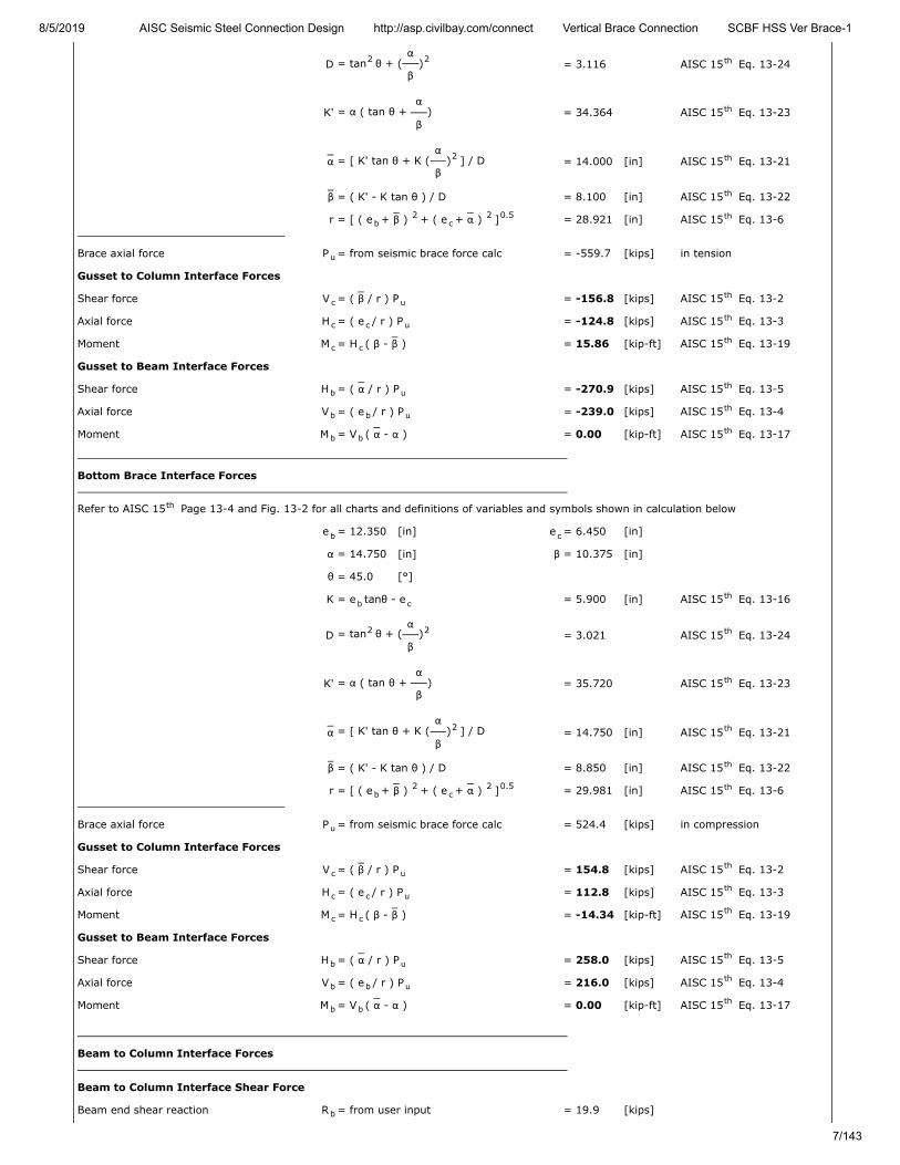
D = tan θ + (α
β) = 3.116 AISC 15 Eq. 13-24
K' = α ( tan θ + α
β) = 34.364 AISC 15 Eq. 13-23
α = [ K' tan θ + K (α
β) ] / D = 14.000 [in] AISC 15 Eq. 13-21
β = ( K' - K tan θ ) / D = 8.100 [in] AISC 15 Eq. 13-22
r = [ ( e + β ) + ( e + α ) ] = 28.921 [in] AISC 15 Eq. 13-6
Brace axial force P = from seismic brace force calc = -559.7 [kips] in tension
Gusset to Column Interface Forces
Shear force V = ( β / r ) P = -156.8 [kips] AISC 15 Eq. 13-2
Axial force H = ( e / r ) P = -124.8 [kips] AISC 15 Eq. 13-3
Moment M = H ( β - β ) = 15.86 [kip-ft] AISC 15 Eq. 13-19
Gusset to Beam Interface Forces
Shear force H = ( α / r ) P = -270.9 [kips] AISC 15 Eq. 13-5
Axial force V = ( e / r ) P = -239.0 [kips] AISC 15 Eq. 13-4
Moment M = V ( α - α ) = 0.00 [kip-ft] AISC 15 Eq. 13-17
Bottom Brace Interface Forces
Refer to AISC 15 Page 13-4 and Fig. 13-2 for all charts and definitions of variables and symbols shown in calculation below
e = 12.350 [in] e = 6.450 [in]
α = 14.750 [in] β = 10.375 [in]
θ = 45.0 [°]
K = e tanθ - e = 5.900 [in] AISC 15 Eq. 13-16
D = tan θ + (α
β) = 3.021 AISC 15 Eq. 13-24
K' = α ( tan θ + α
β) = 35.720 AISC 15 Eq. 13-23
α = [ K' tan θ + K (α
β) ] / D = 14.750 [in] AISC 15 Eq. 13-21
β = ( K' - K tan θ ) / D = 8.850 [in] AISC 15 Eq. 13-22
r = [ ( e + β ) + ( e + α ) ] = 29.981 [in] AISC 15 Eq. 13-6
Brace axial force P = from seismic brace force calc = 524.4 [kips] in compression
Gusset to Column Interface Forces
Shear force V = ( β / r ) P = 154.8 [kips] AISC 15 Eq. 13-2
Axial force H = ( e / r ) P = 112.8 [kips] AISC 15 Eq. 13-3
Moment M = H ( β - β ) = -14.34 [kip-ft] AISC 15 Eq. 13-19
Gusset to Beam Interface Forces
Shear force H = ( α / r ) P = 258.0 [kips] AISC 15 Eq. 13-5
Axial force V = ( e / r ) P = 216.0 [kips] AISC 15 Eq. 13-4
Moment M = V ( α - α ) = 0.00 [kip-ft] AISC 15 Eq. 13-17
Beam to Column Interface Forces
Beam to Column Interface Shear Force
Beam end shear reaction R = from user input = 19.9 [kips]
2 2 th
th
2 th
th
b2
c2 0.5 th
u
c uth
c c uth
c cth
b uth
b b uth
b bth
th
b c
b cth
2 2 th
th
2 th
th
b2
c2 0.5 th
u
c uth
c c uth
c cth
b uth
b b uth
b bth
b
8/5/2019 AISC Seismic Steel Connection Design http://asp.civilbay.com/connect Vertical Brace Connection SCBF HSS Ver Brace-1
8/143
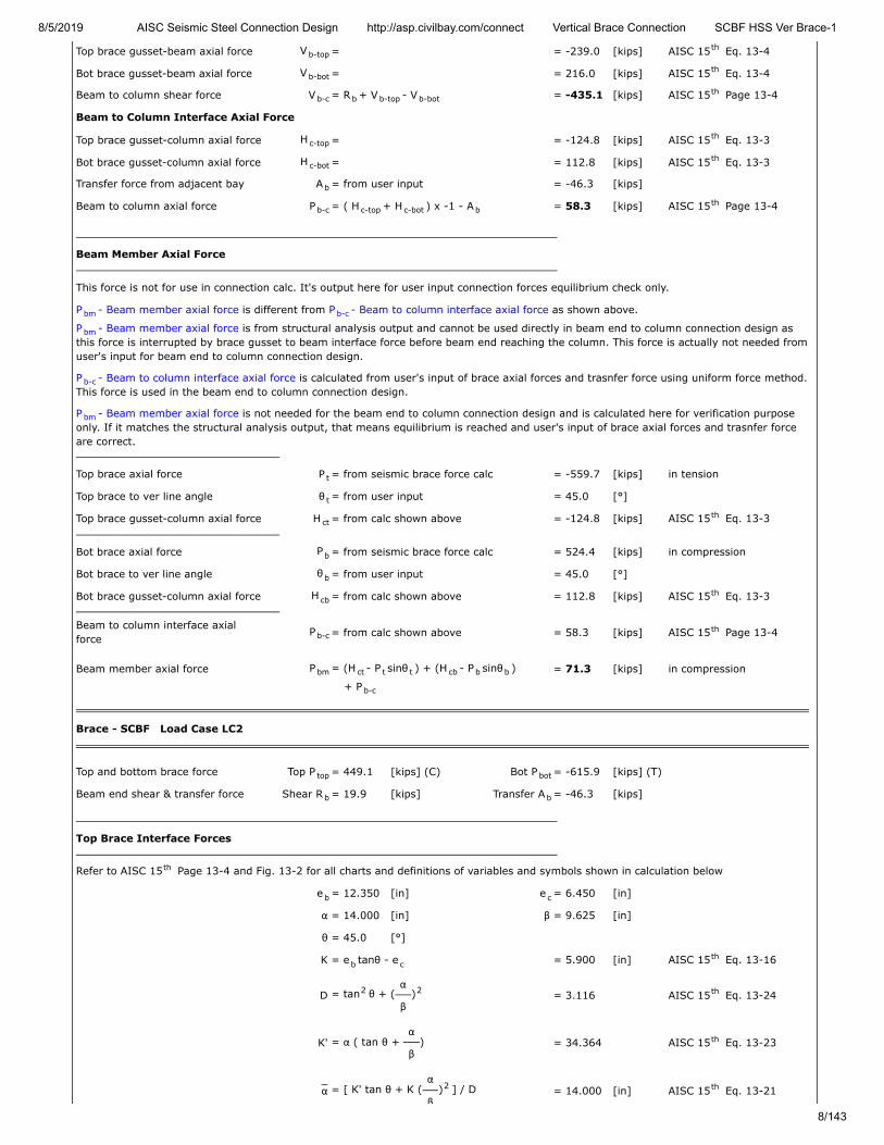
Top brace gusset-beam axial force V = = -239.0 [kips] AISC 15 Eq. 13-4
Bot brace gusset-beam axial force V = = 216.0 [kips] AISC 15 Eq. 13-4
Beam to column shear force V = R + V - V = -435.1 [kips] AISC 15 Page 13-4
Beam to Column Interface Axial Force
Top brace gusset-column axial force H = = -124.8 [kips] AISC 15 Eq. 13-3
Bot brace gusset-column axial force H = = 112.8 [kips] AISC 15 Eq. 13-3
Transfer force from adjacent bay A = from user input = -46.3 [kips]
Beam to column axial force P = ( H + H ) x -1 - A = 58.3 [kips] AISC 15 Page 13-4
Beam Member Axial Force
This force is not for use in connection calc. It's output here for user input connection forces equilibrium check only.
P - Beam member axial force is different from P - Beam to column interface axial force as shown above.
P - Beam member axial force is from structural analysis output and cannot be used directly in beam end to column connection design asthis force is interrupted by brace gusset to beam interface force before beam end reaching the column. This force is actually not needed fromuser's input for beam end to column connection design.
P - Beam to column interface axial force is calculated from user's input of brace axial forces and trasnfer force using uniform force method.This force is used in the beam end to column connection design.
P - Beam member axial force is not needed for the beam end to column connection design and is calculated here for verification purposeonly. If it matches the structural analysis output, that means equilibrium is reached and user's input of brace axial forces and trasnfer forceare correct.
Top brace axial force P = from seismic brace force calc = -559.7 [kips] in tension
Top brace to ver line angle θ = from user input = 45.0 [°]
Top brace gusset-column axial force H = from calc shown above = -124.8 [kips] AISC 15 Eq. 13-3
Bot brace axial force P = from seismic brace force calc = 524.4 [kips] in compression
Bot brace to ver line angle θ = from user input = 45.0 [°]
Bot brace gusset-column axial force H = from calc shown above = 112.8 [kips] AISC 15 Eq. 13-3
Beam to column interface axialforce
P = from calc shown above = 58.3 [kips] AISC 15 Page 13-4
Beam member axial force P = (H - P sinθ ) + (H - P sinθ ) = 71.3 [kips] in compression
+ P
Brace - SCBF Load Case LC2
Top and bottom brace force Top P = 449.1 [kips] (C) Bot P = -615.9 [kips] (T)
Beam end shear & transfer force Shear R = 19.9 [kips] Transfer A = -46.3 [kips]
Top Brace Interface Forces
Refer to AISC 15 Page 13-4 and Fig. 13-2 for all charts and definitions of variables and symbols shown in calculation below
e = 12.350 [in] e = 6.450 [in]
α = 14.000 [in] β = 9.625 [in]
θ = 45.0 [°]
K = e tanθ - e = 5.900 [in] AISC 15 Eq. 13-16
D = tan θ + (α
β) = 3.116 AISC 15 Eq. 13-24
K' = α ( tan θ + α
β) = 34.364 AISC 15 Eq. 13-23
α = [ K' tan θ + K (α
β) ] / D = 14.000 [in] AISC 15 Eq. 13-21
b-topth
b-botth
b-c b b-top b-botth
c-topth
c-botth
b
b-c c-top c-bot bth
bm b-c
bm
b-c
bm
t
t
ctth
b
b
cbth
b-cth
bm ct t t cb b b
b-c
top bot
b b
th
b c
b cth
2 2 th
th
2 th

8/5/2019 AISC Seismic Steel Connection Design http://asp.civilbay.com/connect Vertical Brace Connection SCBF HSS Ver Brace-1
9/143
β
β = ( K' - K tan θ ) / D = 8.100 [in] AISC 15 Eq. 13-22
r = [ ( e + β ) + ( e + α ) ] = 28.921 [in] AISC 15 Eq. 13-6
Brace axial force P = from seismic brace force calc = 449.1 [kips] in compression
Gusset to Column Interface Forces
Shear force V = ( β / r ) P = 125.8 [kips] AISC 15 Eq. 13-2
Axial force H = ( e / r ) P = 100.2 [kips] AISC 15 Eq. 13-3
Moment M = H ( β - β ) = -12.73 [kip-ft] AISC 15 Eq. 13-19
Gusset to Beam Interface Forces
Shear force H = ( α / r ) P = 217.4 [kips] AISC 15 Eq. 13-5
Axial force V = ( e / r ) P = 191.8 [kips] AISC 15 Eq. 13-4
Moment M = V ( α - α ) = 0.00 [kip-ft] AISC 15 Eq. 13-17
Bottom Brace Interface Forces
Refer to AISC 15 Page 13-4 and Fig. 13-2 for all charts and definitions of variables and symbols shown in calculation below
e = 12.350 [in] e = 6.450 [in]
α = 14.750 [in] β = 10.375 [in]
θ = 45.0 [°]
K = e tanθ - e = 5.900 [in] AISC 15 Eq. 13-16
D = tan θ + (α
β) = 3.021 AISC 15 Eq. 13-24
K' = α ( tan θ + α
β) = 35.720 AISC 15 Eq. 13-23
α = [ K' tan θ + K (α
β) ] / D = 14.750 [in] AISC 15 Eq. 13-21
β = ( K' - K tan θ ) / D = 8.850 [in] AISC 15 Eq. 13-22
r = [ ( e + β ) + ( e + α ) ] = 29.981 [in] AISC 15 Eq. 13-6
Brace axial force P = from seismic brace force calc = -615.9 [kips] in tension
Gusset to Column Interface Forces
Shear force V = ( β / r ) P = -181.8 [kips] AISC 15 Eq. 13-2
Axial force H = ( e / r ) P = -132.5 [kips] AISC 15 Eq. 13-3
Moment M = H ( β - β ) = 16.84 [kip-ft] AISC 15 Eq. 13-19
Gusset to Beam Interface Forces
Shear force H = ( α / r ) P = -303.0 [kips] AISC 15 Eq. 13-5
Axial force V = ( e / r ) P = -253.7 [kips] AISC 15 Eq. 13-4
Moment M = V ( α - α ) = 0.00 [kip-ft] AISC 15 Eq. 13-17
Beam to Column Interface Forces
Beam to Column Interface Shear Force
Beam end shear reaction R = from user input = 19.9 [kips]
Top brace gusset-beam axial force V = = 191.8 [kips] AISC 15 Eq. 13-4
Bot brace gusset-beam axial force V = = -253.7 [kips] AISC 15 Eq. 13-4
Beam to column shear force V = R + V - V = 465.4 [kips] AISC 15 Page 13-4
Beam to Column Interface Axial Force
Top brace gusset-column axial force H = = 100.2 [kips] AISC 15 Eq. 13-3
Bot brace gusset-column axial force H = = -132.5 [kips] AISC 15 Eq. 13-3
th
b2
c2 0.5 th
u
c uth
c c uth
c cth
b uth
b b uth
b bth
th
b c
b cth
2 2 th
th
2 th
th
b2
c2 0.5 th
u
c uth
c c uth
c cth
b uth
b b uth
b bth
b
b-topth
b-botth
b-c b b-top b-botth
c-topth
c-botth
8/5/2019 AISC Seismic Steel Connection Design http://asp.civilbay.com/connect Vertical Brace Connection SCBF HSS Ver Brace-1
10/143
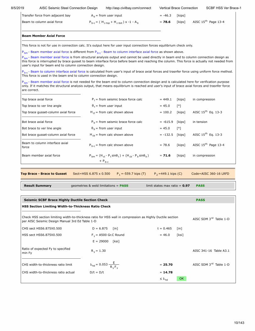
Transfer force from adjacent bay A = from user input = -46.3 [kips]
Beam to column axial force P = ( H + H ) x -1 - A = 78.6 [kips] AISC 15 Page 13-4
Beam Member Axial Force
This force is not for use in connection calc. It's output here for user input connection forces equilibrium check only.
P - Beam member axial force is different from P - Beam to column interface axial force as shown above.
P - Beam member axial force is from structural analysis output and cannot be used directly in beam end to column connection design asthis force is interrupted by brace gusset to beam interface force before beam end reaching the column. This force is actually not needed fromuser's input for beam end to column connection design.
P - Beam to column interface axial force is calculated from user's input of brace axial forces and trasnfer force using uniform force method.This force is used in the beam end to column connection design.
P - Beam member axial force is not needed for the beam end to column connection design and is calculated here for verification purposeonly. If it matches the structural analysis output, that means equilibrium is reached and user's input of brace axial forces and trasnfer forceare correct.
Top brace axial force P = from seismic brace force calc = 449.1 [kips] in compression
Top brace to ver line angle θ = from user input = 45.0 [°]
Top brace gusset-column axial force H = from calc shown above = 100.2 [kips] AISC 15 Eq. 13-3
Bot brace axial force P = from seismic brace force calc = -615.9 [kips] in tension
Bot brace to ver line angle θ = from user input = 45.0 [°]
Bot brace gusset-column axial force H = from calc shown above = -132.5 [kips] AISC 15 Eq. 13-3
Beam to column interface axialforce
P = from calc shown above = 78.6 [kips] AISC 15 Page 13-4
Beam member axial force P = (H - P sinθ ) + (H - P sinθ ) = 71.6 [kips] in compression
+ P
Top Brace - Brace to Gusset Sect=HSS 6.875 x 0.500 P =-559.7 kips (T) P =449.1 kips (C) Code=AISC 360-16 LRFD
Result Summary geometries & weld limitations = PASS limit states max ratio = 0.97 PASS
Seismic SCBF Brace Highly Ductile Section Check PASS
HSS Section Limiting Width-to-Thickness Ratio Check
Check HSS section limiting width-to-thickness ratio for HSS wall in compression as Highly Ductile sectionper AISC Seismic Design Manual 3rd Ed Table 1-D
AISC SDM 3 Table 1-D
CHS sect HSS6.875X0.500 D = 6.875 [in] t = 0.465 [in]
HSS sect HSS6.875X0.500 F = A500 Gr.C Round = 46.0 [ksi]
E = 29000 [ksi]
Ratio of expected Fy to specifiedmin Fy
R = 1.30 AISC 341-16 Table A3.1
CHS width-to-thickness ratio limit λ = 0.053 ER F
= 25.70 AISC SDM 3 Table 1-D
CHS width-to-thickness ratio actual D/t = D/t = 14.78
≤ λ OK
b
b-c c-top c-bot bth
bm b-c
bm
b-c
bm
t
t
ctth
b
b
cbth
b-cth
bm ct t t cb b b
b-c
1 2
rd
y
y
hdy y
rd
hd

8/5/2019 AISC Seismic Steel Connection Design http://asp.civilbay.com/connect Vertical Brace Connection SCBF HSS Ver Brace-1
11/143
Brace Slot Effective Net Area Check PASS
HSS With Reinforcing Plates Effective Net Area
CHS sect HSS6.875X0.500 D = 6.875 [in] t = 0.465 [in]
A = 9.360 [in ]
Gusset plate thickness t = from user input = 0.750 [in]
HSS cut slot width w = t + 1/8" = 0.875 [in]
HSS brace net area A = A - 2 w t = 8.546 [in ]
Reinforcing plate w = 1.250 [in] t = 1.250 [in]
Reinforcing plate area A = w x t = 1.563 [in ]
CHS 1/2 net area A = 0.5A A = 4.273 [in ] r = 2.040 [in]
Reinforce plate A = 1.563 [in ] r = 4.063 [in]
Dist to centroid of comb sect x = A r + A r
A + A = 2.582 [in]
Length of connection L = = 26.000 [in]
Shear lag factor U = 1 - x / L = 0.901 AISC 15 Table D3.1
Total net area A = A + 2 x A = 11.671 [in ]
Total effective net area A = U A = 10.512 [in ]
The brace effective net area shall not be less than the brace gross area AISC 341-16 F2.5b (3)
HSS sect HSS6.875X0.500 A = brace gross area = 9.360 [in ]
Total brace effective net area A = U A = 10.512 [in ]
≥ A OK AISC 341-16 F2.5b (3)
The specified minimum yield strength of the reinforce plate shall be at least the specifiedminimum yield strength of the brace AISC 341-16 F2.5b (3)(i)
HSS sect HSS6.875X0.500 F = A500 Gr.C Round = 46.0 [ksi]
Reinforce plate F = A992 = 50.0 [ksi]
≥ F OK AISC 341-16 F2.5b (3)(i)
Brace Slot to Gusset Plate Weld Limitation Check PASS
Min Fillet Weld Size
Thinner part joined thickness t = = 0.465 [in]
Min fillet weld size allowed w = = 0.188 [in] AISC 15 Table J2.4
Fillet weld size provided w = = 0.250 [in]
≥ w OK
Min Fillet Weld Length
Fillet weld size provided w = = 0.250 [in]
Min fillet weld length allowed L = 4 x w = 1.000 [in] AISC 15 J2.2b
Min fillet weld length L = = 26.000 [in]
≥ L OK
Seismic SCBF LC1 Sect=HSS 6.875 x 0.500 P =-559.7 kips (T) ratio = 0.97 PASS
g2
gp
gp
nb g2
r r
r r r2
1 nb 12
1
22
2
1 1 2 2
1 2
th
n nb r2
e n2
g2
e n2
g
y
yp
y
minth
min
minth
min

8/5/2019 AISC Seismic Steel Connection Design http://asp.civilbay.com/connect Vertical Brace Connection SCBF HSS Ver Brace-1
12/143
HSS Brace Wall - Gusset PL - Shear Yield ratio = 559.7 / 1735.2 = 0.32 PASS
HSS Brace Wall-Gusset Plate Shear Yielding
HSS sect HSS6.875X0.500 wallthick
t = 0.465 [in] F = 46.0 [ksi]
HSS brace wall-gusset overlaplength
L = 26.000 [in]
Ratio of expected Fy to specifiedmin Fy
R = 1.30 AISC 341-16 Table A3.1
Beam axial load P = from seismic load calc = 559.7 [kips]
HSS brace wall-gusset shearyielding
R = 0.6 R F t L x 4 walls = 1735.2 [kips] AISC 15 Eq J4-3
Resistance factor-LRFD φ = 1.00 AISC 15 Eq J4-3
φ R = = 1735.2 [kips]
ratio = 0.32 > P OK
HSS Brace Wall - Gusset PL - Shear Rupture ratio = 559.7 / 1619.1 = 0.35 PASS
HSS Brace Wall-Gusset Plate Shear Yielding
HSS sect HSS6.875X0.500 wallthick
t = 0.465 [in] F = 62.0 [ksi]
HSS brace wall-gusset overlaplength
L = 26.000 [in]
Ratio of expected Fu to specifiedmin Fu
R = 1.20 AISC 341-16 Table A3.1
Beam axial load P = from seismic load calc = 559.7 [kips]
HSS brace wall-gusset shearrupture
R = 0.6 R F t L x 4 walls = 2158.8 [kips] AISC 15 Eq J4-4
Resistance factor-LRFD φ = 0.75 AISC 15 Eq J4-4
φ R = = 1619.1 [kips]
ratio = 0.35 > P OK
Gusset Plate - Block Shear Rupture ratio = 559.7 / 1128.9 = 0.50 PASS
Plate Block Shear - Center Strip
Plate thickness t = 0.750 [in]
Plate strength F = 50.0 [ksi] F = 65.0 [ksi]
C shape weld group size width b = 26.000 [in] depth d = 6.875 [in]
Gross area subject to shear A = b t x 2 = 39.000 [in ]
Net area subject to shear A = A = 39.000 [in ]
Net area subject to tension A = d t = 5.156 [in ]
Block shear strength required V = = 559.7 [kips]
Uniform tension stress factor U = 1.00 AISC 15 Fig C-J4.2
Bolt shear resistance provided R = min (0.6F A , 0.6F A ) + = 1505.2 [kips] AISC 15 Eq J4-5
U F A
Resistance factor-LRFD φ = 0.75 AISC 15 Eq J4-5
φ R = = 1128.9 [kips]
ratio = 0.50 > V OK
y
y
u
n y yth
th
n
u
u
t
u
n t uth
th
n
u
p
y u
gv p2
nv gvb2
nt p2
u
bsth
n u nv y gvth
bs u ntth
n
u
8/5/2019 AISC Seismic Steel Connection Design http://asp.civilbay.com/connect Vertical Brace Connection SCBF HSS Ver Brace-1
13/143
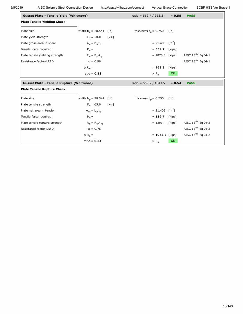
Gusset Plate - Tensile Yield (Whitmore) ratio = 559.7 / 963.3 = 0.58 PASS
Plate Tensile Yielding Check
Plate size width b = 28.541 [in] thickness t = 0.750 [in]
Plate yield strength F = 50.0 [ksi]
Plate gross area in shear A = b t = 21.406 [in ]
Tensile force required P = = 559.7 [kips]
Plate tensile yielding strength R = F A = 1070.3 [kips] AISC 15 Eq J4-1
Resistance factor-LRFD φ = 0.90 AISC 15 Eq J4-1
φ R = = 963.3 [kips]
ratio = 0.58 > P OK
Gusset Plate - Tensile Rupture (Whitmore) ratio = 559.7 / 1043.5 = 0.54 PASS
Plate Tensile Rupture Check
Plate size width b = 28.541 [in] thickness t = 0.750 [in]
Plate tensile strength F = 65.0 [ksi]
Plate net area in tension A = b t = 21.406 [in ]
Tensile force required P = = 559.7 [kips]
Plate tensile rupture strength R = F A = 1391.4 [kips] AISC 15 Eq J4-2
Resistance factor-LRFD φ = 0.75 AISC 15 Eq J4-2
φ R = = 1043.5 [kips] AISC 15 Eq J4-2
ratio = 0.54 > P OK
p p
y
g p p2
u
n y gth
th
n
u
p p
u
nt p p2
u
n u ntth
th
nth
u

8/5/2019 AISC Seismic Steel Connection Design http://asp.civilbay.com/connect Vertical Brace Connection SCBF HSS Ver Brace-1
14/143
Brace Slot to Gusset Plate Weld Strength ratio = 559.7 / 574.4 = 0.97 PASS
Fillet Weld Strength Check
Fillet weld leg size w = ⁄ [in] load angle θ = 0.0 [°]
Electrode strength F = 70.0 [ksi] strength coeff C = 1.00 AISC 15 Table 8-3
Number of weld line n = 2 for double fillet
Load angle coefficient C = ( 1 + 0.5 sin θ ) = 1.00 AISC 15 Page 8-9
Fillet weld shear strength R = 0.6 (C x 70 ksi) 0.707 w n C = 14.847 [kip/in] AISC 15 Eq 8-1
Base metal - brace thickness t = 0.750 [in] tensile F = 65.0 [ksi]
Base metal - brace is in shear, shear rupture as per AISC 15 Eq J4-4 is checked AISC 15 J2.4
Base metal shear rupture R = 0.6 F t = 29.250 [kip/in] AISC 15 Eq J4-4
Double fillet linear shear strength R = min ( R , R ) = 14.847 [kip/in] AISC 15 Eq 9-2
Resistance factor-LRFD φ = 0.75 AISC 15 Eq 8-1
φ R = = 11.135 [kip/in]
Shear resistance required V = = 559.7 [kips]
Fillet weld leg size w = ⁄ [in] max L = 26.000 [in]
when L/w = 104.0 >100 , weld length reduction applied AISC 15 J2.2b
Weld length reduction factor β = 1.2 - 0.002 (L/w) ≤ 1.0 = 0.99 AISC 15 Eq J2-1
Weld length used for design L = β x L = 51.584 [in]
Fillet weld length - double fillet L = = 51.584 [in]
Shear resistance provided φ F = φ R x L = 574.4 [kips]
ratio = 0.97 > V OK
14
EXX 1th
21.5 th
n-w 1 2th
u
th th
n-b uth
n n-w n-bth
th
n
u
14
th
th
n n
u
8/5/2019 AISC Seismic Steel Connection Design http://asp.civilbay.com/connect Vertical Brace Connection SCBF HSS Ver Brace-1
15/143
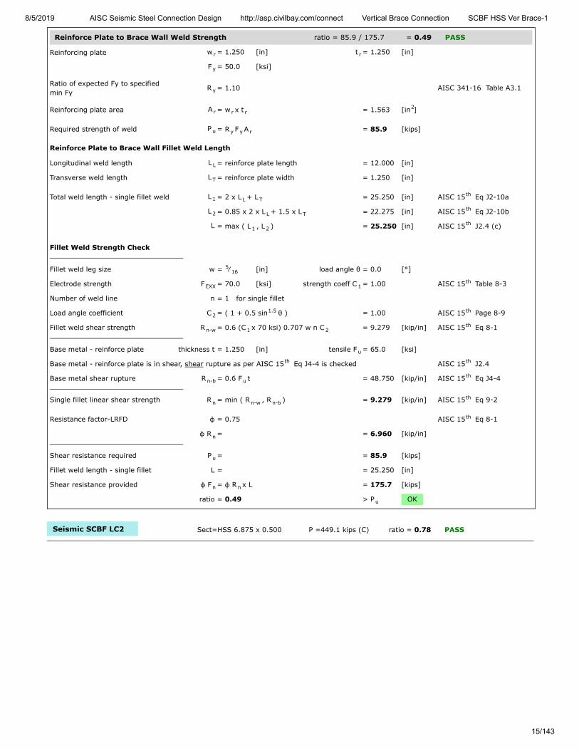
Reinforce Plate to Brace Wall Weld Strength ratio = 85.9 / 175.7 = 0.49 PASS
Reinforcing plate w = 1.250 [in] t = 1.250 [in]
F = 50.0 [ksi]
Ratio of expected Fy to specifiedmin Fy
R = 1.10 AISC 341-16 Table A3.1
Reinforcing plate area A = w x t = 1.563 [in ]
Required strength of weld P = R F A = 85.9 [kips]
Reinforce Plate to Brace Wall Fillet Weld Length
Longitudinal weld length L = reinforce plate length = 12.000 [in]
Transverse weld length L = reinforce plate width = 1.250 [in]
Total weld length - single fillet weld L = 2 x L + L = 25.250 [in] AISC 15 Eq J2-10a
L = 0.85 x 2 x L + 1.5 x L = 22.275 [in] AISC 15 Eq J2-10b
L = max ( L , L ) = 25.250 [in] AISC 15 J2.4 (c)
Fillet Weld Strength Check
Fillet weld leg size w = ⁄ [in] load angle θ = 0.0 [°]
Electrode strength F = 70.0 [ksi] strength coeff C = 1.00 AISC 15 Table 8-3
Number of weld line n = 1 for single fillet
Load angle coefficient C = ( 1 + 0.5 sin θ ) = 1.00 AISC 15 Page 8-9
Fillet weld shear strength R = 0.6 (C x 70 ksi) 0.707 w n C = 9.279 [kip/in] AISC 15 Eq 8-1
Base metal - reinforce plate thickness t = 1.250 [in] tensile F = 65.0 [ksi]
Base metal - reinforce plate is in shear, shear rupture as per AISC 15 Eq J4-4 is checked AISC 15 J2.4
Base metal shear rupture R = 0.6 F t = 48.750 [kip/in] AISC 15 Eq J4-4
Single fillet linear shear strength R = min ( R , R ) = 9.279 [kip/in] AISC 15 Eq 9-2
Resistance factor-LRFD φ = 0.75 AISC 15 Eq 8-1
φ R = = 6.960 [kip/in]
Shear resistance required P = = 85.9 [kips]
Fillet weld length - single fillet L = = 25.250 [in]
Shear resistance provided φ F = φ R x L = 175.7 [kips]
ratio = 0.49 > P OK
Seismic SCBF LC2 Sect=HSS 6.875 x 0.500 P =449.1 kips (C) ratio = 0.78 PASS
r r
y
y
r r r2
u y y r
L
T
1 L Tth
2 L Tth
1 2th
516
EXX 1th
21.5 th
n-w 1 2th
u
th th
n-b uth
n n-w n-bth
th
n
u
n n
u

8/5/2019 AISC Seismic Steel Connection Design http://asp.civilbay.com/connect Vertical Brace Connection SCBF HSS Ver Brace-1
16/143
Gusset Plate - Compression (Whitmore) ratio = 449.1 / 827.9 = 0.54 PASS
Plate Compression Check
Plate size width b = 28.541 [in] thickness t = 0.750 [in]
F = 50.0 [ksi] E = 29000 [ksi]
Plate gross area in compression A = b t = 21.406 [in ]
Plate radius of gyration r = t / 12 = 0.217 [in]
Plate effective length factor K = = 0.60
Plate unbraced length L = = 16.420 [in]
Plate slenderness KL/r = 0.60 x L / r = 45.50
when KL
r > 25 , use Chapter E AISC 15 J4.4 (b)
Elastic buckling stress F = π E
( KL/r ) = 138.23 [ksi] AISC 15 Eq E3-4
when KL
r ≤ 4.71 (
E
F ) = 113.43 AISC 15 E3 (a)
Critical stress F = 0.658 F = 42.98 [ksi] AISC 15 Eq E3-2
Plate compression required P = P = 449.1 = 449.1 [kips]
Plate compression provided R = F x A = 919.9 [kips] AISC 15 Eq E3-1
Resistance factor-LRFD φ = 0.90 AISC 15 E1
φ R = = 827.9 [kips]
ratio = 0.54 > P OK
p p
y
g p p2
p √
u
u
th
e
2
2th
y
0.5 th
cr( F / F )y e y
th
u c
n cr gth
th
n
u
8/5/2019 AISC Seismic Steel Connection Design http://asp.civilbay.com/connect Vertical Brace Connection SCBF HSS Ver Brace-1
17/143
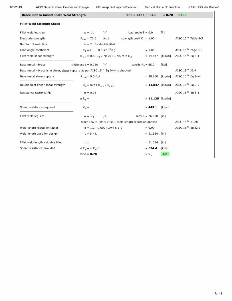
Brace Slot to Gusset Plate Weld Strength ratio = 449.1 / 574.4 = 0.78 PASS
Fillet Weld Strength Check
Fillet weld leg size w = ⁄ [in] load angle θ = 0.0 [°]
Electrode strength F = 70.0 [ksi] strength coeff C = 1.00 AISC 15 Table 8-3
Number of weld line n = 2 for double fillet
Load angle coefficient C = ( 1 + 0.5 sin θ ) = 1.00 AISC 15 Page 8-9
Fillet weld shear strength R = 0.6 (C x 70 ksi) 0.707 w n C = 14.847 [kip/in] AISC 15 Eq 8-1
Base metal - brace thickness t = 0.750 [in] tensile F = 65.0 [ksi]
Base metal - brace is in shear, shear rupture as per AISC 15 Eq J4-4 is checked AISC 15 J2.4
Base metal shear rupture R = 0.6 F t = 29.250 [kip/in] AISC 15 Eq J4-4
Double fillet linear shear strength R = min ( R , R ) = 14.847 [kip/in] AISC 15 Eq 9-2
Resistance factor-LRFD φ = 0.75 AISC 15 Eq 8-1
φ R = = 11.135 [kip/in]
Shear resistance required V = = 449.1 [kips]
Fillet weld leg size w = ⁄ [in] max L = 26.000 [in]
when L/w = 104.0 >100 , weld length reduction applied AISC 15 J2.2b
Weld length reduction factor β = 1.2 - 0.002 (L/w) ≤ 1.0 = 0.99 AISC 15 Eq J2-1
Weld length used for design L = β x L = 51.584 [in]
Fillet weld length - double fillet L = = 51.584 [in]
Shear resistance provided φ F = φ R x L = 574.4 [kips]
ratio = 0.78 > V OK
14
EXX 1th
21.5 th
n-w 1 2th
u
th th
n-b uth
n n-w n-bth
th
n
u
14
th
th
n n
u

8/5/2019 AISC Seismic Steel Connection Design http://asp.civilbay.com/connect Vertical Brace Connection SCBF HSS Ver Brace-1
18/143
Reinforce Plate to Brace Wall Weld Strength ratio = 85.9 / 175.7 = 0.49 PASS
Reinforcing plate w = 1.250 [in] t = 1.250 [in]
F = 50.0 [ksi]
Ratio of expected Fy to specifiedmin Fy
R = 1.10 AISC 341-16 Table A3.1
Reinforcing plate area A = w x t = 1.563 [in ]
Required strength of weld P = R F A = 85.9 [kips]
Reinforce Plate to Brace Wall Fillet Weld Length
Longitudinal weld length L = reinforce plate length = 12.000 [in]
Transverse weld length L = reinforce plate width = 1.250 [in]
Total weld length - single fillet weld L = 2 x L + L = 25.250 [in] AISC 15 Eq J2-10a
L = 0.85 x 2 x L + 1.5 x L = 22.275 [in] AISC 15 Eq J2-10b
L = max ( L , L ) = 25.250 [in] AISC 15 J2.4 (c)
Fillet Weld Strength Check
Fillet weld leg size w = ⁄ [in] load angle θ = 0.0 [°]
Electrode strength F = 70.0 [ksi] strength coeff C = 1.00 AISC 15 Table 8-3
Number of weld line n = 1 for single fillet
Load angle coefficient C = ( 1 + 0.5 sin θ ) = 1.00 AISC 15 Page 8-9
Fillet weld shear strength R = 0.6 (C x 70 ksi) 0.707 w n C = 9.279 [kip/in] AISC 15 Eq 8-1
Base metal - reinforce plate thickness t = 1.250 [in] tensile F = 65.0 [ksi]
Base metal - reinforce plate is in shear, shear rupture as per AISC 15 Eq J4-4 is checked AISC 15 J2.4
Base metal shear rupture R = 0.6 F t = 48.750 [kip/in] AISC 15 Eq J4-4
Single fillet linear shear strength R = min ( R , R ) = 9.279 [kip/in] AISC 15 Eq 9-2
Resistance factor-LRFD φ = 0.75 AISC 15 Eq 8-1
φ R = = 6.960 [kip/in]
Shear resistance required P = = 85.9 [kips]
Fillet weld length - single fillet L = = 25.250 [in]
Shear resistance provided φ F = φ R x L = 175.7 [kips]
ratio = 0.49 > P OK
r r
y
y
r r r2
u y y r
L
T
1 L Tth
2 L Tth
1 2th
516
EXX 1th
21.5 th
n-w 1 2th
u
th th
n-b uth
n n-w n-bth
th
n
u
n n
u
8/5/2019 AISC Seismic Steel Connection Design http://asp.civilbay.com/connect Vertical Brace Connection SCBF HSS Ver Brace-1
19/143
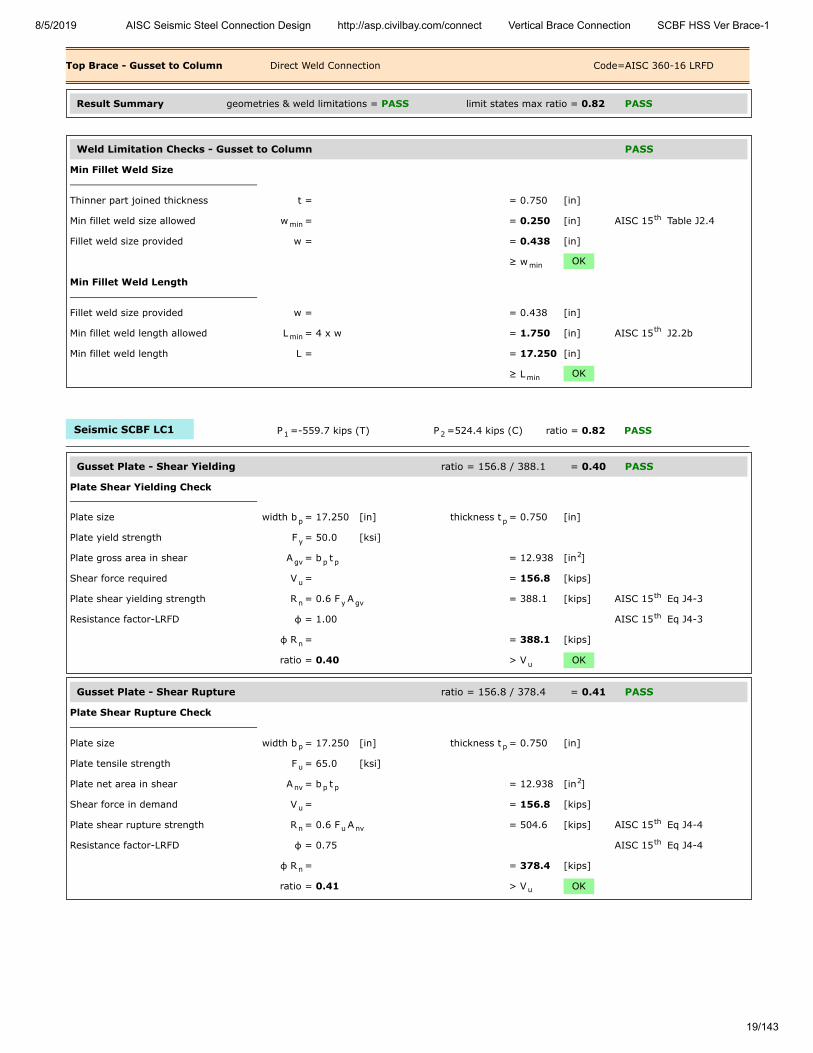
Top Brace - Gusset to Column Direct Weld Connection Code=AISC 360-16 LRFD
Result Summary geometries & weld limitations = PASS limit states max ratio = 0.82 PASS
Weld Limitation Checks - Gusset to Column PASS
Min Fillet Weld Size
Thinner part joined thickness t = = 0.750 [in]
Min fillet weld size allowed w = = 0.250 [in] AISC 15 Table J2.4
Fillet weld size provided w = = 0.438 [in]
≥ w OK
Min Fillet Weld Length
Fillet weld size provided w = = 0.438 [in]
Min fillet weld length allowed L = 4 x w = 1.750 [in] AISC 15 J2.2b
Min fillet weld length L = = 17.250 [in]
≥ L OK
Seismic SCBF LC1 P =-559.7 kips (T) P =524.4 kips (C) ratio = 0.82 PASS
Gusset Plate - Shear Yielding ratio = 156.8 / 388.1 = 0.40 PASS
Plate Shear Yielding Check
Plate size width b = 17.250 [in] thickness t = 0.750 [in]
Plate yield strength F = 50.0 [ksi]
Plate gross area in shear A = b t = 12.938 [in ]
Shear force required V = = 156.8 [kips]
Plate shear yielding strength R = 0.6 F A = 388.1 [kips] AISC 15 Eq J4-3
Resistance factor-LRFD φ = 1.00 AISC 15 Eq J4-3
φ R = = 388.1 [kips]
ratio = 0.40 > V OK
Gusset Plate - Shear Rupture ratio = 156.8 / 378.4 = 0.41 PASS
Plate Shear Rupture Check
Plate size width b = 17.250 [in] thickness t = 0.750 [in]
Plate tensile strength F = 65.0 [ksi]
Plate net area in shear A = b t = 12.938 [in ]
Shear force in demand V = = 156.8 [kips]
Plate shear rupture strength R = 0.6 F A = 504.6 [kips] AISC 15 Eq J4-4
Resistance factor-LRFD φ = 0.75 AISC 15 Eq J4-4
φ R = = 378.4 [kips]
ratio = 0.41 > V OK
minth
min
minth
min
1 2
p p
y
gv p p2
u
n y gvth
th
n
u
p p
u
nv p p2
u
n u nvth
th
n
u

8/5/2019 AISC Seismic Steel Connection Design http://asp.civilbay.com/connect Vertical Brace Connection SCBF HSS Ver Brace-1
20/143
Gusset Plate - Axial Tensile Yield ratio = 124.8 / 582.2 = 0.21 PASS
Plate Tensile Yielding Check
Plate size width b = 17.250 [in] thickness t = 0.750 [in]
Plate yield strength F = 50.0 [ksi]
Plate gross area in shear A = b t = 12.938 [in ]
Tensile force required P = = 124.8 [kips]
Plate tensile yielding strength R = F A = 646.9 [kips] AISC 15 Eq J4-1
Resistance factor-LRFD φ = 0.90 AISC 15 Eq J4-1
φ R = = 582.2 [kips]
ratio = 0.21 > P OK
Gusset Plate - Axial Tensile Rupture ratio = 124.8 / 630.7 = 0.20 PASS
Plate Tensile Rupture Check
Plate size width b = 17.250 [in] thickness t = 0.750 [in]
Plate tensile strength F = 65.0 [ksi]
Plate net area in tension A = b t = 12.938 [in ]
Tensile force required P = = 124.8 [kips]
Plate tensile rupture strength R = F A = 840.9 [kips] AISC 15 Eq J4-2
Resistance factor-LRFD φ = 0.75 AISC 15 Eq J4-2
φ R = = 630.7 [kips] AISC 15 Eq J4-2
ratio = 0.20 > P OK
Gusset Plate - Flexural Yield Interact ratio = = 0.25 PASS
Gusset plate width b = 17.250 [in] thick t = 0.750 [in]
yield F = 50.0 [ksi]
Shear plate - gross area A = b x t = 12.938 [in ]
Shear plate - plastic modulus Z = ( b x t ) / 4 = 55.79 [in ]
Flexural strength available M = φ F Z φ=0.90 = 209.22 [kip-ft]
Flexural strength required M = from gusset interface forces calc = 15.86 [kip-ft]
Axial strength available P = from axial tensile yield check = 582.2 [kips]
Axial strength required P = from gusset interface forces calc = -124.8 [kips]
Shear strength available V = from shear yielding check = 388.1 [kips]
Shear strength required V = from gusset interface forces calc = 156.8 [kips]
Flexural yield interaction ratio = ( V
V) + (
P
P +
M
M ) = 0.25 AISC 15 Eq 10-5
< 1.0 OK
p p
y
g p p2
u
n y gth
th
n
u
p p
u
nt p p2
u
n u ntth
th
nth
u
p p
y
g p p2
p p2p
3
c y p
r
c
r
c
r
r
c
2 r
c
r
c
2 th
8/5/2019 AISC Seismic Steel Connection Design http://asp.civilbay.com/connect Vertical Brace Connection SCBF HSS Ver Brace-1
21/143
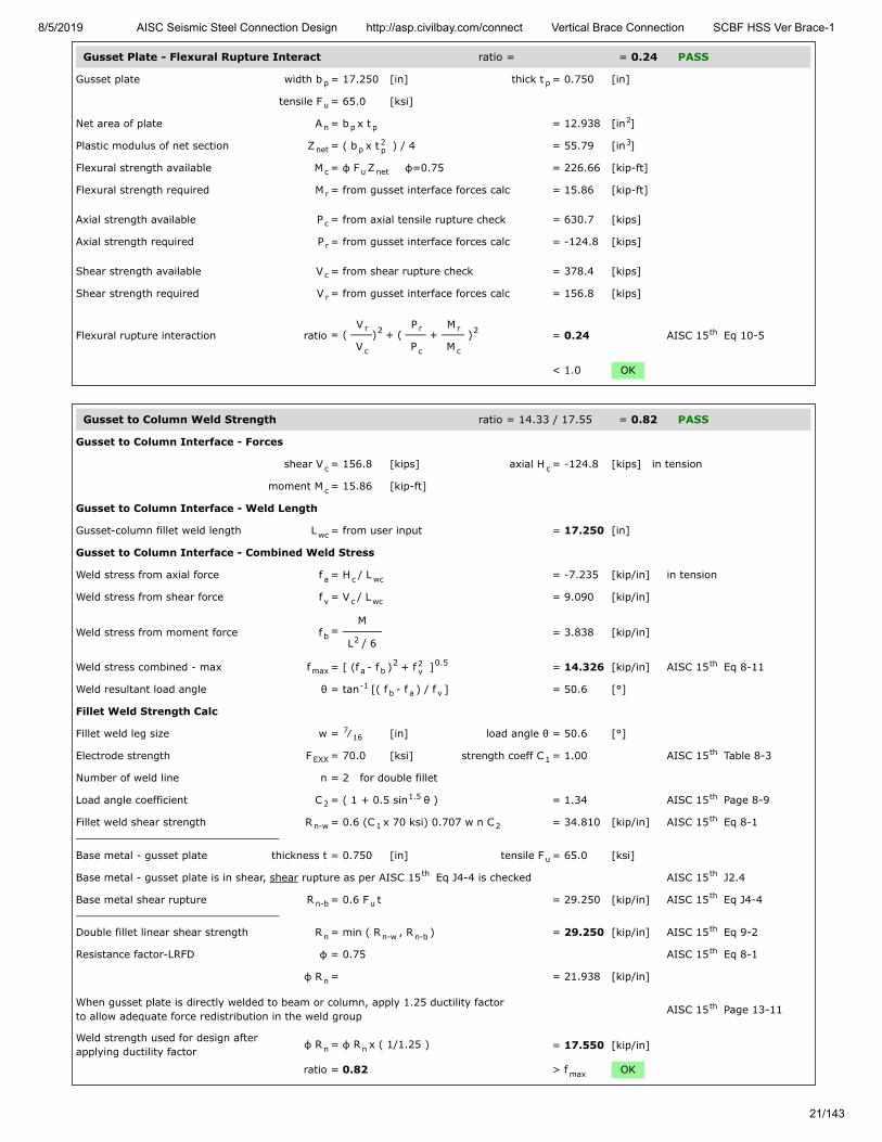
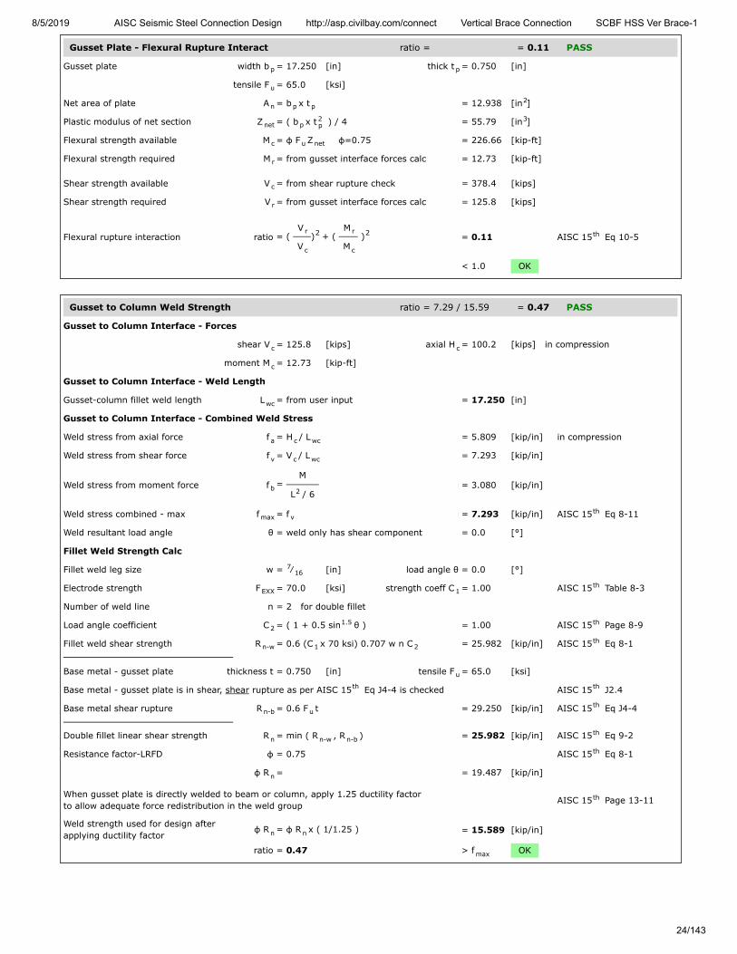
Gusset Plate - Flexural Rupture Interact ratio = = 0.24 PASS
Gusset plate width b = 17.250 [in] thick t = 0.750 [in]
tensile F = 65.0 [ksi]
Net area of plate A = b x t = 12.938 [in ]
Plastic modulus of net section Z = ( b x t ) / 4 = 55.79 [in ]
Flexural strength available M = φ F Z φ=0.75 = 226.66 [kip-ft]
Flexural strength required M = from gusset interface forces calc = 15.86 [kip-ft]
Axial strength available P = from axial tensile rupture check = 630.7 [kips]
Axial strength required P = from gusset interface forces calc = -124.8 [kips]
Shear strength available V = from shear rupture check = 378.4 [kips]
Shear strength required V = from gusset interface forces calc = 156.8 [kips]
Flexural rupture interaction ratio = ( V
V) + (
P
P +
M
M ) = 0.24 AISC 15 Eq 10-5
< 1.0 OK
Gusset to Column Weld Strength ratio = 14.33 / 17.55 = 0.82 PASS
Gusset to Column Interface - Forces
shear V = 156.8 [kips] axial H = -124.8 [kips] in tension
moment M = 15.86 [kip-ft]
Gusset to Column Interface - Weld Length
Gusset-column fillet weld length L = from user input = 17.250 [in]
Gusset to Column Interface - Combined Weld Stress
Weld stress from axial force f = H / L = -7.235 [kip/in] in tension
Weld stress from shear force f = V / L = 9.090 [kip/in]
Weld stress from moment force f = M
L / 6 = 3.838 [kip/in]
Weld stress combined - max f = [ (f - f ) + f ] = 14.326 [kip/in] AISC 15 Eq 8-11
Weld resultant load angle θ = tan [( f - f ) / f ] = 50.6 [°]
Fillet Weld Strength Calc
Fillet weld leg size w = ⁄ [in] load angle θ = 50.6 [°]
Electrode strength F = 70.0 [ksi] strength coeff C = 1.00 AISC 15 Table 8-3
Number of weld line n = 2 for double fillet
Load angle coefficient C = ( 1 + 0.5 sin θ ) = 1.34 AISC 15 Page 8-9
Fillet weld shear strength R = 0.6 (C x 70 ksi) 0.707 w n C = 34.810 [kip/in] AISC 15 Eq 8-1
Base metal - gusset plate thickness t = 0.750 [in] tensile F = 65.0 [ksi]
Base metal - gusset plate is in shear, shear rupture as per AISC 15 Eq J4-4 is checked AISC 15 J2.4
Base metal shear rupture R = 0.6 F t = 29.250 [kip/in] AISC 15 Eq J4-4
Double fillet linear shear strength R = min ( R , R ) = 29.250 [kip/in] AISC 15 Eq 9-2
Resistance factor-LRFD φ = 0.75 AISC 15 Eq 8-1
φ R = = 21.938 [kip/in]
When gusset plate is directly welded to beam or column, apply 1.25 ductility factorto allow adequate force redistribution in the weld group AISC 15 Page 13-11
Weld strength used for design afterapplying ductility factor
φ R = φ R x ( 1/1.25 ) = 17.550 [kip/in]
ratio = 0.82 > f OK
p p
u
n p p2
net p2p
3
c u net
r
c
r
c
r
r
c
2 r
c
r
c
2 th
c c
c
wc
a c wc
v c wc
b 2
max a b2 2
v0.5 th
-1b a v
716
EXX 1th
21.5 th
n-w 1 2th
u
th th
n-b uth
n n-w n-bth
th
n
th
n n
max

8/5/2019 AISC Seismic Steel Connection Design http://asp.civilbay.com/connect Vertical Brace Connection SCBF HSS Ver Brace-1
22/143
Column Web Local Yielding ratio = 168.9 / 768.6 = 0.22 PASS
Gusset Edge Equivalent Normal Force
Refer to AISC DG29 Fig. B-1 for formula below to calculate gusset edge equivalent normal force
Gusset edge axial force N = = -124.8 [kips]
Gusset edge moment force M = = 15.86 [kip-ft]
Gusset edge interface length L = = 17.250 [in]
Gusset edge equivalent normalforce
N = N - 4 ML = -168.9 [kips] AISC DG29 Fig B-1
Concentrated force from gusset P = = 168.9 [kips]
Column section d = 12.900 [in] t = 0.990 [in]
t = 0.610 [in] k = 1.590 [in]
yield F = 50.0 [ksi]
Length of bearing l = Gusset/Column interface length = 17.250 [in]
Column web local yielding strength R = F t ( 5 k + l ) = 768.6 [kips] AISC 15 Eq J10-2
Resistance factor-LRFD φ = 1.00
φ R = = 768.6 [kips]
ratio = 0.22 > P OK
Column Web Shear Strength ratio = 124.8 / 236.1 = 0.53 PASS
W Shape Column Shear Strength Check
W sect W12X106 d = 12.900 [in] t = 0.610 [in]
F = 50.0 [ksi]
Gusset to column axial force V = from gusset interface force calc = 124.8 [kips]
Column shear strength R = 0.6 F d t = 236.1 [kips] AISC 15 Eq J4-3
Resistance factor-LRFD φ = 1.00 AISC 15 Eq J4-3
φ R = = 236.1 [kips]
ratio = 0.53 > V OK
Seismic SCBF LC2 P =449.1 kips (C) P =-615.9 kips (T) ratio = 0.47 PASS
Gusset Plate - Shear Yielding ratio = 125.8 / 388.1 = 0.32 PASS
Plate Shear Yielding Check
Plate size width b = 17.250 [in] thickness t = 0.750 [in]
Plate yield strength F = 50.0 [ksi]
Plate gross area in shear A = b t = 12.938 [in ]
Shear force required V = = 125.8 [kips]
Plate shear yielding strength R = 0.6 F A = 388.1 [kips] AISC 15 Eq J4-3
Resistance factor-LRFD φ = 1.00 AISC 15 Eq J4-3
φ R = = 388.1 [kips]
ratio = 0.32 > V OK
e
u
f
w
y
b
n y w bth
n
u
w
y
u
n y wth
th
n
u
1 2
p p
y
gv p p2
u
n y gvth
th
n
u

8/5/2019 AISC Seismic Steel Connection Design http://asp.civilbay.com/connect Vertical Brace Connection SCBF HSS Ver Brace-1
23/143
Gusset Plate - Shear Rupture ratio = 125.8 / 378.4 = 0.33 PASS
Plate Shear Rupture Check
Plate size width b = 17.250 [in] thickness t = 0.750 [in]
Plate tensile strength F = 65.0 [ksi]
Plate net area in shear A = b t = 12.938 [in ]
Shear force in demand V = = 125.8 [kips]
Plate shear rupture strength R = 0.6 F A = 504.6 [kips] AISC 15 Eq J4-4
Resistance factor-LRFD φ = 0.75 AISC 15 Eq J4-4
φ R = = 378.4 [kips]
ratio = 0.33 > V OK
Gusset Plate - Axial Yield ratio = 100.2 / 582.2 = 0.17 PASS
Plate Tensile Yielding Check
Plate size width b = 17.250 [in] thickness t = 0.750 [in]
Plate yield strength F = 50.0 [ksi]
Plate gross area in shear A = b t = 12.938 [in ]
Tensile force required P = = 100.2 [kips]
Plate tensile yielding strength R = F A = 646.9 [kips] AISC 15 Eq J4-1
Resistance factor-LRFD φ = 0.90 AISC 15 Eq J4-1
φ R = = 582.2 [kips]
ratio = 0.17 > P OK
Gusset Plate - Flexural Yield Interact ratio = = 0.12 PASS
Gusset plate width b = 17.250 [in] thick t = 0.750 [in]
yield F = 50.0 [ksi]
Shear plate - gross area A = b x t = 12.938 [in ]
Shear plate - plastic modulus Z = ( b x t ) / 4 = 55.79 [in ]
Flexural strength available M = φ F Z φ=0.90 = 209.22 [kip-ft]
Flexural strength required M = from gusset interface forces calc = 12.73 [kip-ft]
Axial strength available P = from axial tensile yield check = 582.2 [kips]
Axial strength required P = from gusset interface forces calc = 100.2 [kips]
Shear strength available V = from shear yielding check = 388.1 [kips]
Shear strength required V = from gusset interface forces calc = 125.8 [kips]
Flexural yield interaction ratio = ( V
V) + (
P
P +
M
M ) = 0.12 AISC 15 Eq 10-5
< 1.0 OK
p p
u
nv p p2
u
n u nvth
th
n
u
p p
y
g p p2
u
n y gth
th
n
u
p p
y
g p p2
p p2p
3
c y p
r
c
r
c
r
r
c
2 r
c
r
c
2 th
8/5/2019 AISC Seismic Steel Connection Design http://asp.civilbay.com/connect Vertical Brace Connection SCBF HSS Ver Brace-1
24/143
Gusset Plate - Flexural Rupture Interact ratio = = 0.11 PASS
Gusset plate width b = 17.250 [in] thick t = 0.750 [in]
tensile F = 65.0 [ksi]
Net area of plate A = b x t = 12.938 [in ]
Plastic modulus of net section Z = ( b x t ) / 4 = 55.79 [in ]
Flexural strength available M = φ F Z φ=0.75 = 226.66 [kip-ft]
Flexural strength required M = from gusset interface forces calc = 12.73 [kip-ft]
Shear strength available V = from shear rupture check = 378.4 [kips]
Shear strength required V = from gusset interface forces calc = 125.8 [kips]
Flexural rupture interaction ratio = ( V
V) + (
M
M ) = 0.11 AISC 15 Eq 10-5
< 1.0 OK
Gusset to Column Weld Strength ratio = 7.29 / 15.59 = 0.47 PASS
Gusset to Column Interface - Forces
shear V = 125.8 [kips] axial H = 100.2 [kips] in compression
moment M = 12.73 [kip-ft]
Gusset to Column Interface - Weld Length
Gusset-column fillet weld length L = from user input = 17.250 [in]
Gusset to Column Interface - Combined Weld Stress
Weld stress from axial force f = H / L = 5.809 [kip/in] in compression
Weld stress from shear force f = V / L = 7.293 [kip/in]
Weld stress from moment force f = M
L / 6 = 3.080 [kip/in]
Weld stress combined - max f = f = 7.293 [kip/in] AISC 15 Eq 8-11
Weld resultant load angle θ = weld only has shear component = 0.0 [°]
Fillet Weld Strength Calc
Fillet weld leg size w = ⁄ [in] load angle θ = 0.0 [°]
Electrode strength F = 70.0 [ksi] strength coeff C = 1.00 AISC 15 Table 8-3
Number of weld line n = 2 for double fillet
Load angle coefficient C = ( 1 + 0.5 sin θ ) = 1.00 AISC 15 Page 8-9
Fillet weld shear strength R = 0.6 (C x 70 ksi) 0.707 w n C = 25.982 [kip/in] AISC 15 Eq 8-1
Base metal - gusset plate thickness t = 0.750 [in] tensile F = 65.0 [ksi]
Base metal - gusset plate is in shear, shear rupture as per AISC 15 Eq J4-4 is checked AISC 15 J2.4
Base metal shear rupture R = 0.6 F t = 29.250 [kip/in] AISC 15 Eq J4-4
Double fillet linear shear strength R = min ( R , R ) = 25.982 [kip/in] AISC 15 Eq 9-2
Resistance factor-LRFD φ = 0.75 AISC 15 Eq 8-1
φ R = = 19.487 [kip/in]
When gusset plate is directly welded to beam or column, apply 1.25 ductility factorto allow adequate force redistribution in the weld group AISC 15 Page 13-11
Weld strength used for design afterapplying ductility factor
φ R = φ R x ( 1/1.25 ) = 15.589 [kip/in]
ratio = 0.47 > f OK
p p
u
n p p2
net p2p
3
c u net
r
c
r
r
c
2 r
c
2 th
c c
c
wc
a c wc
v c wc
b 2
max vth
716
EXX 1th
21.5 th
n-w 1 2th
u
th th
n-b uth
n n-w n-bth
th
n
th
n n
max
8/5/2019 AISC Seismic Steel Connection Design http://asp.civilbay.com/connect Vertical Brace Connection SCBF HSS Ver Brace-1
25/143
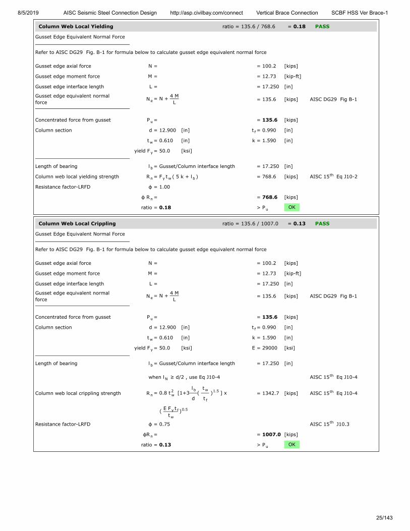
Column Web Local Yielding ratio = 135.6 / 768.6 = 0.18 PASS
Gusset Edge Equivalent Normal Force
Refer to AISC DG29 Fig. B-1 for formula below to calculate gusset edge equivalent normal force
Gusset edge axial force N = = 100.2 [kips]
Gusset edge moment force M = = 12.73 [kip-ft]
Gusset edge interface length L = = 17.250 [in]
Gusset edge equivalent normalforce
N = N + 4 ML = 135.6 [kips] AISC DG29 Fig B-1
Concentrated force from gusset P = = 135.6 [kips]
Column section d = 12.900 [in] t = 0.990 [in]
t = 0.610 [in] k = 1.590 [in]
yield F = 50.0 [ksi]
Length of bearing l = Gusset/Column interface length = 17.250 [in]
Column web local yielding strength R = F t ( 5 k + l ) = 768.6 [kips] AISC 15 Eq J10-2
Resistance factor-LRFD φ = 1.00
φ R = = 768.6 [kips]
ratio = 0.18 > P OK
Column Web Local Crippling ratio = 135.6 / 1007.0 = 0.13 PASS
Gusset Edge Equivalent Normal Force
Refer to AISC DG29 Fig. B-1 for formula below to calculate gusset edge equivalent normal force
Gusset edge axial force N = = 100.2 [kips]
Gusset edge moment force M = = 12.73 [kip-ft]
Gusset edge interface length L = = 17.250 [in]
Gusset edge equivalent normalforce
N = N + 4 ML
= 135.6 [kips] AISC DG29 Fig B-1
Concentrated force from gusset P = = 135.6 [kips]
Column section d = 12.900 [in] t = 0.990 [in]
t = 0.610 [in] k = 1.590 [in]
yield F = 50.0 [ksi] E = 29000 [ksi]
Length of bearing l = Gusset/Column interface length = 17.250 [in]
when l ≥ d/2 , use Eq J10-4 AISC 15 Eq J10-4
Column web local crippling strength R = 0.8 t [1+3l
d(
t
t ) ] x = 1342.7 [kips] AISC 15 Eq J10-4
( E F tt
)
Resistance factor-LRFD φ = 0.75 AISC 15 J10.3
φR = = 1007.0 [kips]
ratio = 0.13 > P OK
e
u
f
w
y
b
n y w bth
n
u
e
u
f
w
y
b
Nth
n2w
b w
f
1.5 th
y f
w
0.5
th
n
u

8/5/2019 AISC Seismic Steel Connection Design http://asp.civilbay.com/connect Vertical Brace Connection SCBF HSS Ver Brace-1
26/143
Column Web Shear Strength ratio = 100.2 / 236.1 = 0.42 PASS
W Shape Column Shear Strength Check
W sect W12X106 d = 12.900 [in] t = 0.610 [in]
F = 50.0 [ksi]
Gusset to column axial force V = from gusset interface force calc = 100.2 [kips]
Column shear strength R = 0.6 F d t = 236.1 [kips] AISC 15 Eq J4-3
Resistance factor-LRFD φ = 1.00 AISC 15 Eq J4-3
φ R = = 236.1 [kips]
ratio = 0.42 > V OK
w
y
u
n y wth
th
n
u

8/5/2019 AISC Seismic Steel Connection Design http://asp.civilbay.com/connect Vertical Brace Connection SCBF HSS Ver Brace-1
27/143
Top Brace - Gusset to Beam Direct Weld Connection Code=AISC 360-16 LRFD
Result Summary geometries & weld limitations = PASS limit states max ratio = 0.79 PASS
Brace Weld Limitation Checks - Gusset to Beam PASS
Min Fillet Weld Size
Thinner part joined thickness t = = 0.750 [in]
Min fillet weld size allowed w = = 0.250 [in] AISC 15 Table J2.4
Fillet weld size provided w = = 0.438 [in]
≥ w OK
Min Fillet Weld Length
Fillet weld size provided w = = 0.438 [in]
Min fillet weld length allowed L = 4 x w = 1.750 [in] AISC 15 J2.2b
Min fillet weld length L = = 26.000 [in]
≥ L OK
Seismic SCBF LC1 P =-559.7 kips (T) P =524.4 kips (C) ratio = 0.79 PASS
Gusset Plate - Shear Yielding ratio = 270.9 / 585.0 = 0.46 PASS
Plate Shear Yielding Check
Plate size width b = 26.000 [in] thickness t = 0.750 [in]
Plate yield strength F = 50.0 [ksi]
Plate gross area in shear A = b t = 19.500 [in ]
Shear force required V = = 270.9 [kips]
Plate shear yielding strength R = 0.6 F A = 585.0 [kips] AISC 15 Eq J4-3
Resistance factor-LRFD φ = 1.00 AISC 15 Eq J4-3
φ R = = 585.0 [kips]
ratio = 0.46 > V OK
Gusset Plate - Shear Rupture ratio = 270.9 / 570.4 = 0.47 PASS
Plate Shear Rupture Check
Plate size width b = 26.000 [in] thickness t = 0.750 [in]
Plate tensile strength F = 65.0 [ksi]
Plate net area in shear A = b t = 19.500 [in ]
Shear force in demand V = = 270.9 [kips]
Plate shear rupture strength R = 0.6 F A = 760.5 [kips] AISC 15 Eq J4-4
Resistance factor-LRFD φ = 0.75 AISC 15 Eq J4-4
φ R = = 570.4 [kips]
ratio = 0.47 > V OK
minth
min
minth
min
1 2
p p
y
gv p p2
u
n y gvth
th
n
u
p p
u
nv p p2
u
n u nvth
th
n
u

8/5/2019 AISC Seismic Steel Connection Design http://asp.civilbay.com/connect Vertical Brace Connection SCBF HSS Ver Brace-1
28/143
Gusset Plate - Axial Tensile Yield ratio = 239.0 / 877.5 = 0.27 PASS
Plate Tensile Yielding Check
Plate size width b = 26.000 [in] thickness t = 0.750 [in]
Plate yield strength F = 50.0 [ksi]
Plate gross area in shear A = b t = 19.500 [in ]
Tensile force required P = = 239.0 [kips]
Plate tensile yielding strength R = F A = 975.0 [kips] AISC 15 Eq J4-1
Resistance factor-LRFD φ = 0.90 AISC 15 Eq J4-1
φ R = = 877.5 [kips]
ratio = 0.27 > P OK
Gusset Plate - Axial Tensile Rupture ratio = 239.0 / 950.6 = 0.25 PASS
Plate Tensile Rupture Check
Plate size width b = 26.000 [in] thickness t = 0.750 [in]
Plate tensile strength F = 65.0 [ksi]
Plate net area in tension A = b t = 19.500 [in ]
Tensile force required P = = 239.0 [kips]
Plate tensile rupture strength R = F A = 1267.5 [kips] AISC 15 Eq J4-2
Resistance factor-LRFD φ = 0.75 AISC 15 Eq J4-2
φ R = = 950.6 [kips] AISC 15 Eq J4-2
ratio = 0.25 > P OK
Gusset Plate - Flexural Yield Interact ratio = = 0.29 PASS
Gusset plate width b = 26.000 [in] thick t = 0.750 [in]
yield F = 50.0 [ksi]
Shear plate - gross area A = b x t = 19.500 [in ]
Shear plate - plastic modulus Z = ( b x t ) / 4 = 126.75 [in ]
Flexural strength available M = φ F Z φ=0.90 = 475.31 [kip-ft]
Flexural strength required M = from gusset interface forces calc = 0.00 [kip-ft]
Axial strength available P = from axial tensile yield check = 877.5 [kips]
Axial strength required P = from gusset interface forces calc = -239.0 [kips]
Shear strength available V = from shear yielding check = 585.0 [kips]
Shear strength required V = from gusset interface forces calc = 270.9 [kips]
Flexural yield interaction ratio = ( V
V) + (
P
P +
M
M ) = 0.29 AISC 15 Eq 10-5
< 1.0 OK
p p
y
g p p2
u
n y gth
th
n
u
p p
u
nt p p2
u
n u ntth
th
nth
u
p p
y
g p p2
p p2p
3
c y p
r
c
r
c
r
r
c
2 r
c
r
c
2 th

8/5/2019 AISC Seismic Steel Connection Design http://asp.civilbay.com/connect Vertical Brace Connection SCBF HSS Ver Brace-1
29/143
Gusset Plate - Flexural Rupture Interact ratio = = 0.29 PASS
Gusset plate width b = 26.000 [in] thick t = 0.750 [in]
tensile F = 65.0 [ksi]
Net area of plate A = b x t = 19.500 [in ]
Plastic modulus of net section Z = ( b x t ) / 4 = 126.75 [in ]
Flexural strength available M = φ F Z φ=0.75 = 514.92 [kip-ft]
Flexural strength required M = from gusset interface forces calc = 0.00 [kip-ft]
Axial strength available P = from axial tensile rupture check = 950.6 [kips]
Axial strength required P = from gusset interface forces calc = -239.0 [kips]
Shear strength available V = from shear rupture check = 570.4 [kips]
Shear strength required V = from gusset interface forces calc = 270.9 [kips]
Flexural rupture interaction ratio = ( V
V) + (
P
P +
M
M ) = 0.29 AISC 15 Eq 10-5
< 1.0 OK
Gusset to Beam Weld Strength ratio = 13.89 / 17.55 = 0.79 PASS
Gusset to Beam Interface - Forces
shear H = 270.9 [kips] axial V = -239.0 [kips] in tension
moment M = 0.00 [kip-ft]
Gusset-beam fillet weld length L = = 26.000 [in]
Gusset to Beam Interface - Combined Weld Stress
Weld stress from axial force f = V / L = -9.192 [kip/in] in tension
Weld stress from shear force f = H / L = 10.419 [kip/in]
Weld stress from moment force f = M
L / 6 = 0.000 [kip/in]
Weld stress combined - max f = [ (f - f ) + f ] = 13.895 [kip/in] AISC 15 Eq 8-11
Weld resultant load angle θ = tan [( f - f ) / f ] = 41.4 [°]
Fillet Weld Strength Calc
Fillet weld leg size w = ⁄ [in] load angle θ = 41.4 [°]
Electrode strength F = 70.0 [ksi] strength coeff C = 1.00 AISC 15 Table 8-3
Number of weld line n = 2 for double fillet
Load angle coefficient C = ( 1 + 0.5 sin θ ) = 1.27 AISC 15 Page 8-9
Fillet weld shear strength R = 0.6 (C x 70 ksi) 0.707 w n C = 32.973 [kip/in] AISC 15 Eq 8-1
Base metal - gusset plate thickness t = 0.750 [in] tensile F = 65.0 [ksi]
Base metal - gusset plate is in shear, shear rupture as per AISC 15 Eq J4-4 is checked AISC 15 J2.4
Base metal shear rupture R = 0.6 F t = 29.250 [kip/in] AISC 15 Eq J4-4
Double fillet linear shear strength R = min ( R , R ) = 29.250 [kip/in] AISC 15 Eq 9-2
Resistance factor-LRFD φ = 0.75 AISC 15 Eq 8-1
φ R = = 21.938 [kip/in]
When gusset plate is directly welded to beam or column, apply 1.25 ductility factorto allow adequate force redistribution in the weld group AISC 15 Page 13-11
Weld strength used for design afterapplying ductility factor
φ R = φ R x ( 1/1.25 ) = 17.550 [kip/in]
ratio = 0.79 > f OK
p p
u
n p p2
net p2p
3
c u net
r
c
r
c
r
r
c
2 r
c
r
c
2 th
b b
b
w
a b wb
v b wb
b 2
max a b2 2
v0.5 th
-1b a v
716
EXX 1th
21.5 th
n-w 1 2th
u
th th
n-b uth
n n-w n-bth
th
n
th
n n
max

8/5/2019 AISC Seismic Steel Connection Design http://asp.civilbay.com/connect Vertical Brace Connection SCBF HSS Ver Brace-1
30/143
Beam Web Local Yielding ratio = 239.0 / 974.2 = 0.25 PASS
Concentrated force from gusset P = = 239.0 [kips]
Beam section d = 24.700 [in] t = 1.090 [in]
t = 0.650 [in] k = 1.590 [in]
yield F = 50.0 [ksi]
Length of bearing l = Gusset/Beam interface length = 26.000 [in]
Gusset plate corner clip clip = from user input = 1.000 [in]
Distance from normal force appliedpoint to member end
l = 0.5 l + clip = 14.000 [in]
when l ≤ d , use AISC 15 Eq J10-3 AISC 15 Eq J10-3
Beam web local yielding strength R = F t ( 2.5 k + l ) = 974.2 [kips] AISC 15 Eq J10-3
Resistance factor-LRFD φ = 1.00
φ R = = 974.2 [kips]
ratio = 0.25 > P OK
Seismic SCBF LC2 P =449.1 kips (C) P =-615.9 kips (T) ratio = 0.54 PASS
Gusset Plate - Shear Yielding ratio = 217.4 / 585.0 = 0.37 PASS
Plate Shear Yielding Check
Plate size width b = 26.000 [in] thickness t = 0.750 [in]
Plate yield strength F = 50.0 [ksi]
Plate gross area in shear A = b t = 19.500 [in ]
Shear force required V = = 217.4 [kips]
Plate shear yielding strength R = 0.6 F A = 585.0 [kips] AISC 15 Eq J4-3
Resistance factor-LRFD φ = 1.00 AISC 15 Eq J4-3
φ R = = 585.0 [kips]
ratio = 0.37 > V OK
Gusset Plate - Shear Rupture ratio = 217.4 / 570.4 = 0.38 PASS
Plate Shear Rupture Check
Plate size width b = 26.000 [in] thickness t = 0.750 [in]
Plate tensile strength F = 65.0 [ksi]
Plate net area in shear A = b t = 19.500 [in ]
Shear force in demand V = = 217.4 [kips]
Plate shear rupture strength R = 0.6 F A = 760.5 [kips] AISC 15 Eq J4-4
Resistance factor-LRFD φ = 0.75 AISC 15 Eq J4-4
φ R = = 570.4 [kips]
ratio = 0.38 > V OK
u
f
w
y
b
N b
Nth th
n y w bth
n
u
1 2
p p
y
gv p p2
u
n y gvth
th
n
u
p p
u
nv p p2
u
n u nvth
th
n
u

8/5/2019 AISC Seismic Steel Connection Design http://asp.civilbay.com/connect Vertical Brace Connection SCBF HSS Ver Brace-1
31/143
Gusset Plate - Axial Yield ratio = 191.8 / 877.5 = 0.22 PASS
Plate Tensile Yielding Check
Plate size width b = 26.000 [in] thickness t = 0.750 [in]
Plate yield strength F = 50.0 [ksi]
Plate gross area in shear A = b t = 19.500 [in ]
Tensile force required P = = 191.8 [kips]
Plate tensile yielding strength R = F A = 975.0 [kips] AISC 15 Eq J4-1
Resistance factor-LRFD φ = 0.90 AISC 15 Eq J4-1
φ R = = 877.5 [kips]
ratio = 0.22 > P OK
Gusset Plate - Flexural Yield Interact ratio = = 0.19 PASS
Gusset plate width b = 26.000 [in] thick t = 0.750 [in]
yield F = 50.0 [ksi]
Shear plate - gross area A = b x t = 19.500 [in ]
Shear plate - plastic modulus Z = ( b x t ) / 4 = 126.75 [in ]
Flexural strength available M = φ F Z φ=0.90 = 475.31 [kip-ft]
Flexural strength required M = from gusset interface forces calc = 0.00 [kip-ft]
Axial strength available P = from axial tensile yield check = 877.5 [kips]
Axial strength required P = from gusset interface forces calc = 191.8 [kips]
Shear strength available V = from shear yielding check = 585.0 [kips]
Shear strength required V = from gusset interface forces calc = 217.4 [kips]
Flexural yield interaction ratio = ( V
V) + (
P
P +
M
M ) = 0.19 AISC 15 Eq 10-5
< 1.0 OK
Gusset Plate - Flexural Rupture Interact ratio = = 0.15 PASS
Gusset plate width b = 26.000 [in] thick t = 0.750 [in]
tensile F = 65.0 [ksi]
Net area of plate A = b x t = 19.500 [in ]
Plastic modulus of net section Z = ( b x t ) / 4 = 126.75 [in ]
Flexural strength available M = φ F Z φ=0.75 = 514.92 [kip-ft]
Flexural strength required M = from gusset interface forces calc = 0.00 [kip-ft]
Shear strength available V = from shear rupture check = 570.4 [kips]
Shear strength required V = from gusset interface forces calc = 217.4 [kips]
Flexural rupture interaction ratio = ( V
V) + (
M
M ) = 0.15 AISC 15 Eq 10-5
< 1.0 OK
p p
y
g p p2
u
n y gth
th
n
u
p p
y
g p p2
p p2p
3
c y p
r
c
r
c
r
r
c
2 r
c
r
c
2 th
p p
u
n p p2
net p2p
3
c u net
r
c
r
r
c
2 r
c
2 th

8/5/2019 AISC Seismic Steel Connection Design http://asp.civilbay.com/connect Vertical Brace Connection SCBF HSS Ver Brace-1
32/143
Gusset to Beam Weld Strength ratio = 8.36 / 15.59 = 0.54 PASS
Gusset to Beam Interface - Forces
shear H = 217.4 [kips] axial V = 191.8 [kips] in compression
moment M = 0.00 [kip-ft]
Gusset-beam fillet weld length L = = 26.000 [in]
Gusset to Beam Interface - Combined Weld Stress
Weld stress from axial force f = V / L = 0.000 [kip/in] in compression
Weld stress from shear force f = H / L = 8.362 [kip/in]
Weld stress from moment force f = M
L / 6 = 0.000 [kip/in]
Weld stress combined - max f = f = 8.362 [kip/in] AISC 15 Eq 8-11
Weld resultant load angle θ = weld only has shear component = 0.0 [°]
Fillet Weld Strength Calc
Fillet weld leg size w = ⁄ [in] load angle θ = 0.0 [°]
Electrode strength F = 70.0 [ksi] strength coeff C = 1.00 AISC 15 Table 8-3
Number of weld line n = 2 for double fillet
Load angle coefficient C = ( 1 + 0.5 sin θ ) = 1.00 AISC 15 Page 8-9
Fillet weld shear strength R = 0.6 (C x 70 ksi) 0.707 w n C = 25.982 [kip/in] AISC 15 Eq 8-1
Base metal - gusset plate thickness t = 0.750 [in] tensile F = 65.0 [ksi]
Base metal - gusset plate is in shear, shear rupture as per AISC 15 Eq J4-4 is checked AISC 15 J2.4
Base metal shear rupture R = 0.6 F t = 29.250 [kip/in] AISC 15 Eq J4-4
Double fillet linear shear strength R = min ( R , R ) = 25.982 [kip/in] AISC 15 Eq 9-2
Resistance factor-LRFD φ = 0.75 AISC 15 Eq 8-1
φ R = = 19.487 [kip/in]
When gusset plate is directly welded to beam or column, apply 1.25 ductility factorto allow adequate force redistribution in the weld group AISC 15 Page 13-11
Weld strength used for design afterapplying ductility factor
φ R = φ R x ( 1/1.25 ) = 15.589 [kip/in]
ratio = 0.54 > f OK
Beam Web Local Yielding ratio = 191.8 / 974.2 = 0.20 PASS
Concentrated force from gusset P = = 191.8 [kips]
Beam section d = 24.700 [in] t = 1.090 [in]
t = 0.650 [in] k = 1.590 [in]
yield F = 50.0 [ksi]
Length of bearing l = Gusset/Beam interface length = 26.000 [in]
Gusset plate corner clip clip = from user input = 1.000 [in]
Distance from normal force appliedpoint to member end
l = 0.5 l + clip = 14.000 [in]
when l ≤ d , use AISC 15 Eq J10-3 AISC 15 Eq J10-3
Beam web local yielding strength R = F t ( 2.5 k + l ) = 974.2 [kips] AISC 15 Eq J10-3
Resistance factor-LRFD φ = 1.00
φ R = = 974.2 [kips]
ratio = 0.20 > P OK
b b
b
w
a b wb
v b wb
b 2
max vth
716
EXX 1th
21.5 th
n-w 1 2th
u
th th
n-b uth
n n-w n-bth
th
n
th
n n
max
u
f
w
y
b
N b
Nth th
n y w bth
n
u

8/5/2019 AISC Seismic Steel Connection Design http://asp.civilbay.com/connect Vertical Brace Connection SCBF HSS Ver Brace-1
33/143
Beam Web Local Crippling ratio = 191.8 / 970.1 = 0.20 PASS
Concentrated force from gusset P = = 191.8 [kips]
Beam section d = 24.700 [in] t = 1.090 [in]
t = 0.650 [in] k = 1.590 [in]
yield F = 50.0 [ksi] E = 29000 [ksi]
Length of bearing l = Gusset/Beam interface length = 26.000 [in]
Gusset plate corner clip clip = from user input = 1.000 [in]
Distance from normal force appliedpoint to member end
l = 0.5 l + clip = 14.000 [in]
when l ≥ d/2 , use Eq J10-4 AISC 15 Eq J10-4
Beam web local crippling strength R = 0.8 t [1+3l
d(
t
t ) ] x = 1293.5 [kips] AISC 15 Eq J10-4
( E F tt
)
Resistance factor-LRFD φ = 0.75 AISC 15 J10.3
φR = = 970.1 [kips]
ratio = 0.20 > P OK
u
f
w
y
b
N b
Nth
n2w
b w
f
1.5 th
y f
w
0.5
th
n
u

8/5/2019 AISC Seismic Steel Connection Design http://asp.civilbay.com/connect Vertical Brace Connection SCBF HSS Ver Brace-1
34/143
Bot Brace - Brace to Gusset Sect=HSS 7.500 x 0.500 P =524.4 kips (C) P =-615.9 kips (T) Code=AISC 360-16 LRFD
Result Summary geometries & weld limitations = PASS limit states max ratio = 1.01 FAIL
Seismic SCBF Brace Highly Ductile Section Check PASS
HSS Section Limiting Width-to-Thickness Ratio Check
Check HSS section limiting width-to-thickness ratio for HSS wall in compression as Highly Ductile sectionper AISC Seismic Design Manual 3rd Ed Table 1-D
AISC SDM 3 Table 1-D
CHS sect HSS7.500X0.500 D = 7.500 [in] t = 0.465 [in]
HSS sect HSS7.500X0.500 F = A500 Gr.C Round = 46.0 [ksi]
E = 29000 [ksi]
Ratio of expected Fy to specifiedmin Fy
R = 1.30 AISC 341-16 Table A3.1
CHS width-to-thickness ratio limit λ = 0.053 ER F
= 25.70 AISC SDM 3 Table 1-D
CHS width-to-thickness ratio actual D/t = D/t = 16.13
≤ λ OK
1 2
rd
y
y
hdy y
rd
hd

8/5/2019 AISC Seismic Steel Connection Design http://asp.civilbay.com/connect Vertical Brace Connection SCBF HSS Ver Brace-1
35/143
Brace Slot Effective Net Area Check PASS
HSS With Reinforcing Plates Effective Net Area
CHS sect HSS7.500X0.500 D = 7.500 [in] t = 0.465 [in]
A = 10.300 [in ]
Gusset plate thickness t = from user input = 0.750 [in]
HSS cut slot width w = t + 1/8" = 0.875 [in]
HSS brace net area A = A - 2 w t = 9.486 [in ]
Reinforcing plate w = 1.500 [in] t = 1.500 [in]
Reinforcing plate area A = w x t = 2.250 [in ]
CHS 1/2 net area A = 0.5A A = 4.743 [in ] r = 2.239 [in]
Reinforce plate A = 2.250 [in ] r = 4.500 [in]
Dist to centroid of comb sect x = A r + A r
A + A = 2.967 [in]
Length of connection L = = 28.000 [in]
Shear lag factor U = 1 - x / L = 0.894 AISC 15 Table D3.1
Total net area A = A + 2 x A = 13.986 [in ]
Total effective net area A = U A = 12.504 [in ]
The brace effective net area shall not be less than the brace gross area AISC 341-16 F2.5b (3)
HSS sect HSS7.500X0.500 A = brace gross area = 10.300 [in ]
Total brace effective net area A = U A = 12.504 [in ]
≥ A OK AISC 341-16 F2.5b (3)
The specified minimum yield strength of the reinforce plate shall be at least the specifiedminimum yield strength of the brace AISC 341-16 F2.5b (3)(i)
HSS sect HSS7.500X0.500 F = A500 Gr.C Round = 46.0 [ksi]
Reinforce plate F = A992 = 50.0 [ksi]
≥ F OK AISC 341-16 F2.5b (3)(i)
Brace Slot to Gusset Plate Weld Limitation Check PASS
Min Fillet Weld Size
Thinner part joined thickness t = = 0.465 [in]
Min fillet weld size allowed w = = 0.188 [in] AISC 15 Table J2.4
Fillet weld size provided w = = 0.250 [in]
≥ w OK
Min Fillet Weld Length
Fillet weld size provided w = = 0.250 [in]
Min fillet weld length allowed L = 4 x w = 1.000 [in] AISC 15 J2.2b
Min fillet weld length L = = 28.000 [in]
≥ L OK
Seismic SCBF LC1 Sect=HSS 7.500 x 0.500 P =524.4 kips (C) ratio = 0.91 PASS
g2
gp
gp
nb g2
r r
r r r2
1 nb 12
1
22
2
1 1 2 2
1 2
th
n nb r2
e n2
g2
e n2
g
y
yp
y
minth
min
minth
min

8/5/2019 AISC Seismic Steel Connection Design http://asp.civilbay.com/connect Vertical Brace Connection SCBF HSS Ver Brace-1
36/143
Gusset Plate - Compression (Whitmore) ratio = 524.4 / 871.7 = 0.60 PASS
Plate Compression Check
Plate size width b = 30.663 [in] thickness t = 0.750 [in]
F = 50.0 [ksi] E = 29000 [ksi]
Plate gross area in compression A = b t = 22.997 [in ]
Plate radius of gyration r = t / 12 = 0.217 [in]
Plate effective length factor K = = 0.60
Plate unbraced length L = = 17.481 [in]
Plate slenderness KL/r = 0.60 x L / r = 48.44
when KL
r > 25 , use Chapter E AISC 15 J4.4 (b)
Elastic buckling stress F = π E
( KL/r ) = 121.96 [ksi] AISC 15 Eq E3-4
when KL
r ≤ 4.71 (
E
F ) = 113.43 AISC 15 E3 (a)
Critical stress F = 0.658 F = 42.12 [ksi] AISC 15 Eq E3-2
Plate compression required P = P = 524.4 = 524.4 [kips]
Plate compression provided R = F x A = 968.5 [kips] AISC 15 Eq E3-1
Resistance factor-LRFD φ = 0.90 AISC 15 E1
φ R = = 871.7 [kips]
ratio = 0.60 > P OK
p p
y
g p p2
p √
u
u
th
e
2
2th
y
0.5 th
cr( F / F )y e y
th
u c
n cr gth
th
n
u

8/5/2019 AISC Seismic Steel Connection Design http://asp.civilbay.com/connect Vertical Brace Connection SCBF HSS Ver Brace-1
37/143
Brace Slot to Gusset Plate Weld Strength ratio = 524.4 / 608.6 = 0.86 PASS
Fillet Weld Strength Check
Fillet weld leg size w = ⁄ [in] load angle θ = 0.0 [°]
Electrode strength F = 70.0 [ksi] strength coeff C = 1.00 AISC 15 Table 8-3
Number of weld line n = 2 for double fillet
Load angle coefficient C = ( 1 + 0.5 sin θ ) = 1.00 AISC 15 Page 8-9
Fillet weld shear strength R = 0.6 (C x 70 ksi) 0.707 w n C = 14.847 [kip/in] AISC 15 Eq 8-1
Base metal - brace thickness t = 0.750 [in] tensile F = 65.0 [ksi]
Base metal - brace is in shear, shear rupture as per AISC 15 Eq J4-4 is checked AISC 15 J2.4
Base metal shear rupture R = 0.6 F t = 29.250 [kip/in] AISC 15 Eq J4-4
Double fillet linear shear strength R = min ( R , R ) = 14.847 [kip/in] AISC 15 Eq 9-2
Resistance factor-LRFD φ = 0.75 AISC 15 Eq 8-1
φ R = = 11.135 [kip/in]
Shear resistance required V = = 524.4 [kips]
Fillet weld leg size w = ⁄ [in] max L = 28.000 [in]
when L/w = 112.0 >100 , weld length reduction applied AISC 15 J2.2b
Weld length reduction factor β = 1.2 - 0.002 (L/w) ≤ 1.0 = 0.98 AISC 15 Eq J2-1
Weld length used for design L = β x L = 54.656 [in]
Fillet weld length - double fillet L = = 54.656 [in]
Shear resistance provided φ F = φ R x L = 608.6 [kips]
ratio = 0.86 > V OK
14
EXX 1th
21.5 th
n-w 1 2th
u
th th
n-b uth
n n-w n-bth
th
n
u
14
th
th
n n
u

8/5/2019 AISC Seismic Steel Connection Design http://asp.civilbay.com/connect Vertical Brace Connection SCBF HSS Ver Brace-1
38/143
Reinforce Plate to Brace Wall Weld Strength ratio = 123.8 / 136.4 = 0.91 PASS
Reinforcing plate w = 1.500 [in] t = 1.500 [in]
F = 50.0 [ksi]
Ratio of expected Fy to specifiedmin Fy
R = 1.10 AISC 341-16 Table A3.1
Reinforcing plate area A = w x t = 2.250 [in ]
Required strength of weld P = R F A = 123.8 [kips]
Reinforce Plate to Brace Wall Fillet Weld Length
Longitudinal weld length L = reinforce plate length = 11.500 [in]
Transverse weld length L = reinforce plate width = 1.500 [in]
Total weld length - single fillet weld L = 2 x L + L = 24.500 [in] AISC 15 Eq J2-10a
L = 0.85 x 2 x L + 1.5 x L = 21.800 [in] AISC 15 Eq J2-10b
L = max ( L , L ) = 24.500 [in] AISC 15 J2.4 (c)
Fillet Weld Strength Check
Fillet weld leg size w = ⁄ [in] load angle θ = 0.0 [°]
Electrode strength F = 70.0 [ksi] strength coeff C = 1.00 AISC 15 Table 8-3
Number of weld line n = 1 for single fillet
Load angle coefficient C = ( 1 + 0.5 sin θ ) = 1.00 AISC 15 Page 8-9
Fillet weld shear strength R = 0.6 (C x 70 ksi) 0.707 w n C = 7.424 [kip/in] AISC 15 Eq 8-1
Base metal - reinforce plate thickness t = 1.500 [in] tensile F = 65.0 [ksi]
Base metal - reinforce plate is in shear, shear rupture as per AISC 15 Eq J4-4 is checked AISC 15 J2.4
Base metal shear rupture R = 0.6 F t = 58.500 [kip/in] AISC 15 Eq J4-4
Single fillet linear shear strength R = min ( R , R ) = 7.424 [kip/in] AISC 15 Eq 9-2
Resistance factor-LRFD φ = 0.75 AISC 15 Eq 8-1
φ R = = 5.568 [kip/in]
Shear resistance required P = = 123.8 [kips]
Fillet weld length - single fillet L = = 24.500 [in]
Shear resistance provided φ F = φ R x L = 136.4 [kips]
ratio = 0.91 > P OK
Seismic SCBF LC2 Sect=HSS 7.500 x 0.500 P =-615.9 kips (T) ratio = 1.01 FAIL
r r
y
y
r r r2
u y y r
L
T
1 L Tth
2 L Tth
1 2th
14
EXX 1th
21.5 th
n-w 1 2th
u
th th
n-b uth
n n-w n-bth
th
n
u
n n
u
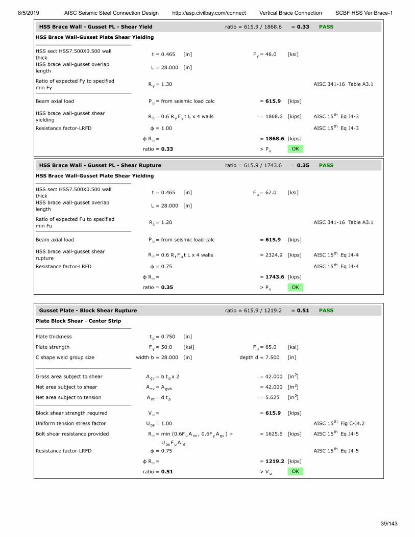
8/5/2019 AISC Seismic Steel Connection Design http://asp.civilbay.com/connect Vertical Brace Connection SCBF HSS Ver Brace-1
39/143
HSS Brace Wall - Gusset PL - Shear Yield ratio = 615.9 / 1868.6 = 0.33 PASS
HSS Brace Wall-Gusset Plate Shear Yielding
HSS sect HSS7.500X0.500 wallthick
t = 0.465 [in] F = 46.0 [ksi]
HSS brace wall-gusset overlaplength
L = 28.000 [in]
Ratio of expected Fy to specifiedmin Fy
R = 1.30 AISC 341-16 Table A3.1
Beam axial load P = from seismic load calc = 615.9 [kips]
HSS brace wall-gusset shearyielding
R = 0.6 R F t L x 4 walls = 1868.6 [kips] AISC 15 Eq J4-3
Resistance factor-LRFD φ = 1.00 AISC 15 Eq J4-3
φ R = = 1868.6 [kips]
ratio = 0.33 > P OK
HSS Brace Wall - Gusset PL - Shear Rupture ratio = 615.9 / 1743.6 = 0.35 PASS
HSS Brace Wall-Gusset Plate Shear Yielding
HSS sect HSS7.500X0.500 wallthick
t = 0.465 [in] F = 62.0 [ksi]
HSS brace wall-gusset overlaplength
L = 28.000 [in]
Ratio of expected Fu to specifiedmin Fu
R = 1.20 AISC 341-16 Table A3.1
Beam axial load P = from seismic load calc = 615.9 [kips]
HSS brace wall-gusset shearrupture
R = 0.6 R F t L x 4 walls = 2324.9 [kips] AISC 15 Eq J4-4
Resistance factor-LRFD φ = 0.75 AISC 15 Eq J4-4
φ R = = 1743.6 [kips]
ratio = 0.35 > P OK
Gusset Plate - Block Shear Rupture ratio = 615.9 / 1219.2 = 0.51 PASS
Plate Block Shear - Center Strip
Plate thickness t = 0.750 [in]
Plate strength F = 50.0 [ksi] F = 65.0 [ksi]
C shape weld group size width b = 28.000 [in] depth d = 7.500 [in]
Gross area subject to shear A = b t x 2 = 42.000 [in ]
Net area subject to shear A = A = 42.000 [in ]
Net area subject to tension A = d t = 5.625 [in ]
Block shear strength required V = = 615.9 [kips]
Uniform tension stress factor U = 1.00 AISC 15 Fig C-J4.2
Bolt shear resistance provided R = min (0.6F A , 0.6F A ) + = 1625.6 [kips] AISC 15 Eq J4-5
U F A
Resistance factor-LRFD φ = 0.75 AISC 15 Eq J4-5
φ R = = 1219.2 [kips]
ratio = 0.51 > V OK
y
y
u
n y yth
th
n
u
u
t
u
n t uth
th
n
u
p
y u
gv p2
nv gvb2
nt p2
u
bsth
n u nv y gvth
bs u ntth
n
u

8/5/2019 AISC Seismic Steel Connection Design http://asp.civilbay.com/connect Vertical Brace Connection SCBF HSS Ver Brace-1
40/143
Gusset Plate - Tensile Yield (Whitmore) ratio = 615.9 / 1034.9 = 0.60 PASS
Plate Tensile Yielding Check
Plate size width b = 30.663 [in] thickness t = 0.750 [in]
Plate yield strength F = 50.0 [ksi]
Plate gross area in shear A = b t = 22.997 [in ]
Tensile force required P = = 615.9 [kips]
Plate tensile yielding strength R = F A = 1149.9 [kips] AISC 15 Eq J4-1
Resistance factor-LRFD φ = 0.90 AISC 15 Eq J4-1
φ R = = 1034.9 [kips]
ratio = 0.60 > P OK
Gusset Plate - Tensile Rupture (Whitmore) ratio = 615.9 / 1121.1 = 0.55 PASS
Plate Tensile Rupture Check
Plate size width b = 30.663 [in] thickness t = 0.750 [in]
Plate tensile strength F = 65.0 [ksi]
Plate net area in tension A = b t = 22.997 [in ]
Tensile force required P = = 615.9 [kips]
Plate tensile rupture strength R = F A = 1494.8 [kips] AISC 15 Eq J4-2
Resistance factor-LRFD φ = 0.75 AISC 15 Eq J4-2
φ R = = 1121.1 [kips] AISC 15 Eq J4-2
ratio = 0.55 > P OK
p p
y
g p p2
u
n y gth
th
n
u
p p
u
nt p p2
u
n u ntth
th
nth
u

8/5/2019 AISC Seismic Steel Connection Design http://asp.civilbay.com/connect Vertical Brace Connection SCBF HSS Ver Brace-1
41/143
Brace Slot to Gusset Plate Weld Strength ratio = 615.9 / 608.6 = 1.01 FAIL
Fillet Weld Strength Check
Fillet weld leg size w = ⁄ [in] load angle θ = 0.0 [°]
Electrode strength F = 70.0 [ksi] strength coeff C = 1.00 AISC 15 Table 8-3
Number of weld line n = 2 for double fillet
Load angle coefficient C = ( 1 + 0.5 sin θ ) = 1.00 AISC 15 Page 8-9
Fillet weld shear strength R = 0.6 (C x 70 ksi) 0.707 w n C = 14.847 [kip/in] AISC 15 Eq 8-1
Base metal - brace thickness t = 0.750 [in] tensile F = 65.0 [ksi]
Base metal - brace is in shear, shear rupture as per AISC 15 Eq J4-4 is checked AISC 15 J2.4
Base metal shear rupture R = 0.6 F t = 29.250 [kip/in] AISC 15 Eq J4-4
Double fillet linear shear strength R = min ( R , R ) = 14.847 [kip/in] AISC 15 Eq 9-2
Resistance factor-LRFD φ = 0.75 AISC 15 Eq 8-1
φ R = = 11.135 [kip/in]
Shear resistance required V = = 615.9 [kips]
Fillet weld leg size w = ⁄ [in] max L = 28.000 [in]
when L/w = 112.0 >100 , weld length reduction applied AISC 15 J2.2b
Weld length reduction factor β = 1.2 - 0.002 (L/w) ≤ 1.0 = 0.98 AISC 15 Eq J2-1
Weld length used for design L = β x L = 54.656 [in]
Fillet weld length - double fillet L = = 54.656 [in]
Shear resistance provided φ F = φ R x L = 608.6 [kips]
ratio = 1.01 < V NG
14
EXX 1th
21.5 th
n-w 1 2th
u
th th
n-b uth
n n-w n-bth
th
n
u
14
th
th
n n
u
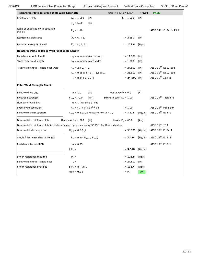
8/5/2019 AISC Seismic Steel Connection Design http://asp.civilbay.com/connect Vertical Brace Connection SCBF HSS Ver Brace-1
42/143
Reinforce Plate to Brace Wall Weld Strength ratio = 123.8 / 136.4 = 0.91 PASS
Reinforcing plate w = 1.500 [in] t = 1.500 [in]
F = 50.0 [ksi]
Ratio of expected Fy to specifiedmin Fy
R = 1.10 AISC 341-16 Table A3.1
Reinforcing plate area A = w x t = 2.250 [in ]
Required strength of weld P = R F A = 123.8 [kips]
Reinforce Plate to Brace Wall Fillet Weld Length
Longitudinal weld length L = reinforce plate length = 11.500 [in]
Transverse weld length L = reinforce plate width = 1.500 [in]
Total weld length - single fillet weld L = 2 x L + L = 24.500 [in] AISC 15 Eq J2-10a
L = 0.85 x 2 x L + 1.5 x L = 21.800 [in] AISC 15 Eq J2-10b
L = max ( L , L ) = 24.500 [in] AISC 15 J2.4 (c)
Fillet Weld Strength Check
Fillet weld leg size w = ⁄ [in] load angle θ = 0.0 [°]
Electrode strength F = 70.0 [ksi] strength coeff C = 1.00 AISC 15 Table 8-3
Number of weld line n = 1 for single fillet
Load angle coefficient C = ( 1 + 0.5 sin θ ) = 1.00 AISC 15 Page 8-9
Fillet weld shear strength R = 0.6 (C x 70 ksi) 0.707 w n C = 7.424 [kip/in] AISC 15 Eq 8-1
Base metal - reinforce plate thickness t = 1.500 [in] tensile F = 65.0 [ksi]
Base metal - reinforce plate is in shear, shear rupture as per AISC 15 Eq J4-4 is checked AISC 15 J2.4
Base metal shear rupture R = 0.6 F t = 58.500 [kip/in] AISC 15 Eq J4-4
Single fillet linear shear strength R = min ( R , R ) = 7.424 [kip/in] AISC 15 Eq 9-2
Resistance factor-LRFD φ = 0.75 AISC 15 Eq 8-1
φ R = = 5.568 [kip/in]
Shear resistance required P = = 123.8 [kips]
Fillet weld length - single fillet L = = 24.500 [in]
Shear resistance provided φ F = φ R x L = 136.4 [kips]
ratio = 0.91 > P OK
r r
y
y
r r r2
u y y r
L
T
1 L Tth
2 L Tth
1 2th
14
EXX 1th
21.5 th
n-w 1 2th
u
th th
n-b uth
n n-w n-bth
th
n
u
n n
u

8/5/2019 AISC Seismic Steel Connection Design http://asp.civilbay.com/connect Vertical Brace Connection SCBF HSS Ver Brace-1
43/143
Bot Brace - Gusset to Column Direct Weld Connection Code=AISC 360-16 LRFD
Result Summary geometries & weld limitations = PASS limit states max ratio = 0.98 PASS
Weld Limitation Checks - Gusset to Column PASS
Min Fillet Weld Size
Thinner part joined thickness t = = 0.750 [in]
Min fillet weld size allowed w = = 0.250 [in] AISC 15 Table J2.4
Fillet weld size provided w = = 0.313 [in]
≥ w OK
Min Fillet Weld Length
Fillet weld size provided w = = 0.313 [in]
Min fillet weld length allowed L = 4 x w = 1.250 [in] AISC 15 J2.2b
Min fillet weld length L = = 18.750 [in]
≥ L OK
Seismic SCBF LC1 P =-559.7 kips (T) P =524.4 kips (C) ratio = 0.74 PASS
Gusset Plate - Shear Yielding ratio = 154.8 / 421.9 = 0.37 PASS
Plate Shear Yielding Check
Plate size width b = 18.750 [in] thickness t = 0.750 [in]
Plate yield strength F = 50.0 [ksi]
Plate gross area in shear A = b t = 14.063 [in ]
Shear force required V = = 154.8 [kips]
Plate shear yielding strength R = 0.6 F A = 421.9 [kips] AISC 15 Eq J4-3
Resistance factor-LRFD φ = 1.00 AISC 15 Eq J4-3
φ R = = 421.9 [kips]
ratio = 0.37 > V OK
Gusset Plate - Shear Rupture ratio = 154.8 / 411.3 = 0.38 PASS
Plate Shear Rupture Check
Plate size width b = 18.750 [in] thickness t = 0.750 [in]
Plate tensile strength F = 65.0 [ksi]
Plate net area in shear A = b t = 14.063 [in ]
Shear force in demand V = = 154.8 [kips]
Plate shear rupture strength R = 0.6 F A = 548.4 [kips] AISC 15 Eq J4-4
Resistance factor-LRFD φ = 0.75 AISC 15 Eq J4-4
φ R = = 411.3 [kips]
ratio = 0.38 > V OK
minth
min
minth
min
1 2
p p
y
gv p p2
u
n y gvth
th
n
u
p p
u
nv p p2
u
n u nvth
th
n
u
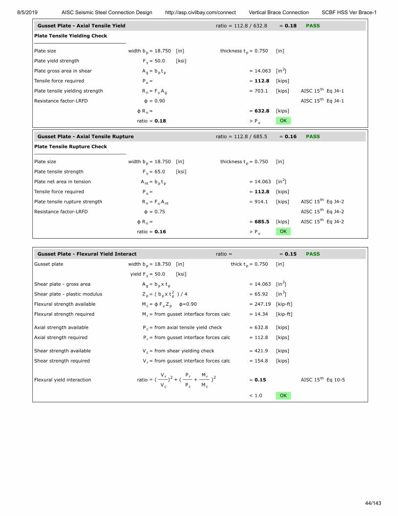
8/5/2019 AISC Seismic Steel Connection Design http://asp.civilbay.com/connect Vertical Brace Connection SCBF HSS Ver Brace-1
44/143
Gusset Plate - Axial Tensile Yield ratio = 112.8 / 632.8 = 0.18 PASS
Plate Tensile Yielding Check
Plate size width b = 18.750 [in] thickness t = 0.750 [in]
Plate yield strength F = 50.0 [ksi]
Plate gross area in shear A = b t = 14.063 [in ]
Tensile force required P = = 112.8 [kips]
Plate tensile yielding strength R = F A = 703.1 [kips] AISC 15 Eq J4-1
Resistance factor-LRFD φ = 0.90 AISC 15 Eq J4-1
φ R = = 632.8 [kips]
ratio = 0.18 > P OK
Gusset Plate - Axial Tensile Rupture ratio = 112.8 / 685.5 = 0.16 PASS
Plate Tensile Rupture Check
Plate size width b = 18.750 [in] thickness t = 0.750 [in]
Plate tensile strength F = 65.0 [ksi]
Plate net area in tension A = b t = 14.063 [in ]
Tensile force required P = = 112.8 [kips]
Plate tensile rupture strength R = F A = 914.1 [kips] AISC 15 Eq J4-2
Resistance factor-LRFD φ = 0.75 AISC 15 Eq J4-2
φ R = = 685.5 [kips] AISC 15 Eq J4-2
ratio = 0.16 > P OK
Gusset Plate - Flexural Yield Interact ratio = = 0.15 PASS
Gusset plate width b = 18.750 [in] thick t = 0.750 [in]
yield F = 50.0 [ksi]
Shear plate - gross area A = b x t = 14.063 [in ]
Shear plate - plastic modulus Z = ( b x t ) / 4 = 65.92 [in ]
Flexural strength available M = φ F Z φ=0.90 = 247.19 [kip-ft]
Flexural strength required M = from gusset interface forces calc = 14.34 [kip-ft]
Axial strength available P = from axial tensile yield check = 632.8 [kips]
Axial strength required P = from gusset interface forces calc = 112.8 [kips]
Shear strength available V = from shear yielding check = 421.9 [kips]
Shear strength required V = from gusset interface forces calc = 154.8 [kips]
Flexural yield interaction ratio = ( V
V) + (
P
P +
M
M ) = 0.15 AISC 15 Eq 10-5
< 1.0 OK
p p
y
g p p2
u
n y gth
th
n
u
p p
u
nt p p2
u
n u ntth
th
nth
u
p p
y
g p p2
p p2p
3
c y p
r
c
r
c
r
r
c
2 r
c
r
c
2 th
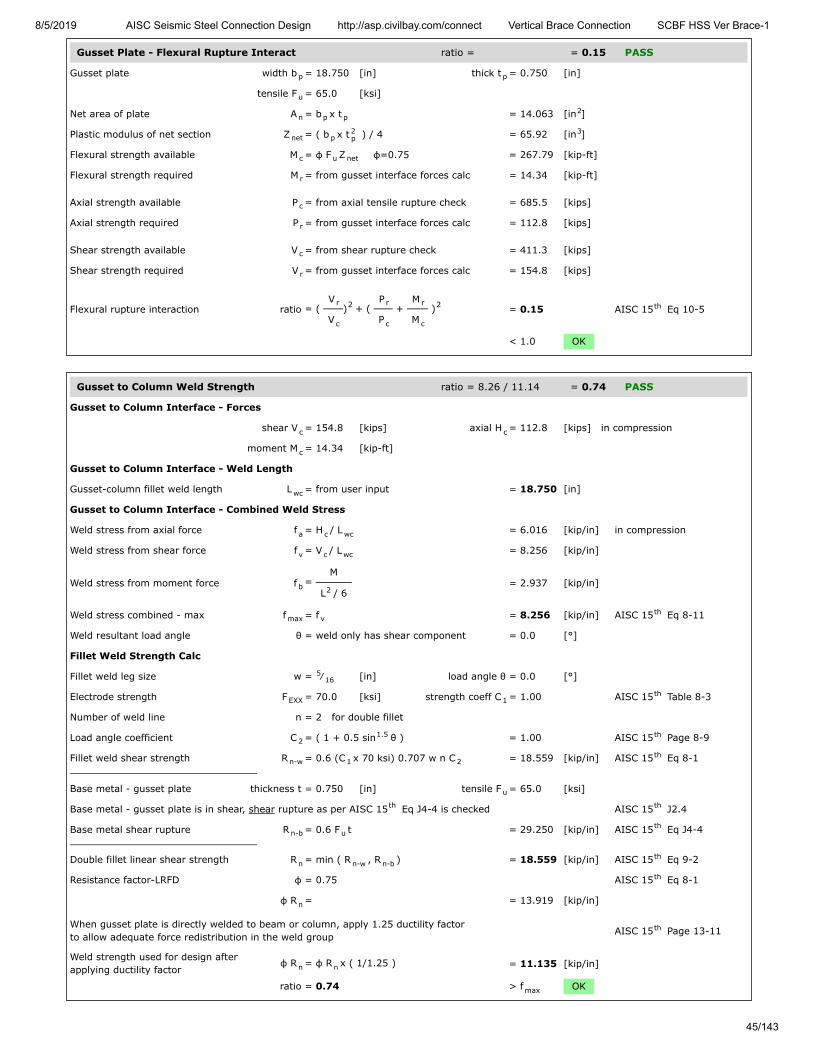
8/5/2019 AISC Seismic Steel Connection Design http://asp.civilbay.com/connect Vertical Brace Connection SCBF HSS Ver Brace-1
45/143
Gusset Plate - Flexural Rupture Interact ratio = = 0.15 PASS
Gusset plate width b = 18.750 [in] thick t = 0.750 [in]
tensile F = 65.0 [ksi]
Net area of plate A = b x t = 14.063 [in ]
Plastic modulus of net section Z = ( b x t ) / 4 = 65.92 [in ]
Flexural strength available M = φ F Z φ=0.75 = 267.79 [kip-ft]
Flexural strength required M = from gusset interface forces calc = 14.34 [kip-ft]
Axial strength available P = from axial tensile rupture check = 685.5 [kips]
Axial strength required P = from gusset interface forces calc = 112.8 [kips]
Shear strength available V = from shear rupture check = 411.3 [kips]
Shear strength required V = from gusset interface forces calc = 154.8 [kips]
Flexural rupture interaction ratio = ( V
V) + (
P
P +
M
M ) = 0.15 AISC 15 Eq 10-5
< 1.0 OK
Gusset to Column Weld Strength ratio = 8.26 / 11.14 = 0.74 PASS
Gusset to Column Interface - Forces
shear V = 154.8 [kips] axial H = 112.8 [kips] in compression
moment M = 14.34 [kip-ft]
Gusset to Column Interface - Weld Length
Gusset-column fillet weld length L = from user input = 18.750 [in]
Gusset to Column Interface - Combined Weld Stress
Weld stress from axial force f = H / L = 6.016 [kip/in] in compression
Weld stress from shear force f = V / L = 8.256 [kip/in]
Weld stress from moment force f = M
L / 6 = 2.937 [kip/in]
Weld stress combined - max f = f = 8.256 [kip/in] AISC 15 Eq 8-11
Weld resultant load angle θ = weld only has shear component = 0.0 [°]
Fillet Weld Strength Calc
Fillet weld leg size w = ⁄ [in] load angle θ = 0.0 [°]
Electrode strength F = 70.0 [ksi] strength coeff C = 1.00 AISC 15 Table 8-3
Number of weld line n = 2 for double fillet
Load angle coefficient C = ( 1 + 0.5 sin θ ) = 1.00 AISC 15 Page 8-9
Fillet weld shear strength R = 0.6 (C x 70 ksi) 0.707 w n C = 18.559 [kip/in] AISC 15 Eq 8-1
Base metal - gusset plate thickness t = 0.750 [in] tensile F = 65.0 [ksi]
Base metal - gusset plate is in shear, shear rupture as per AISC 15 Eq J4-4 is checked AISC 15 J2.4
Base metal shear rupture R = 0.6 F t = 29.250 [kip/in] AISC 15 Eq J4-4
Double fillet linear shear strength R = min ( R , R ) = 18.559 [kip/in] AISC 15 Eq 9-2
Resistance factor-LRFD φ = 0.75 AISC 15 Eq 8-1
φ R = = 13.919 [kip/in]
When gusset plate is directly welded to beam or column, apply 1.25 ductility factorto allow adequate force redistribution in the weld group AISC 15 Page 13-11
Weld strength used for design afterapplying ductility factor
φ R = φ R x ( 1/1.25 ) = 11.135 [kip/in]
ratio = 0.74 > f OK
p p
u
n p p2
net p2p
3
c u net
r
c
r
c
r
r
c
2 r
c
r
c
2 th
c c
c
wc
a c wc
v c wc
b 2
max vth
516
EXX 1th
21.5 th
n-w 1 2th
u
th th
n-b uth
n n-w n-bth
th
n
th
n n
max

8/5/2019 AISC Seismic Steel Connection Design http://asp.civilbay.com/connect Vertical Brace Connection SCBF HSS Ver Brace-1
46/143
Column Web Local Yielding ratio = 149.5 / 814.4 = 0.18 PASS
Gusset Edge Equivalent Normal Force
Refer to AISC DG29 Fig. B-1 for formula below to calculate gusset edge equivalent normal force
Gusset edge axial force N = = 112.8 [kips]
Gusset edge moment force M = = 14.34 [kip-ft]
Gusset edge interface length L = = 18.750 [in]
Gusset edge equivalent normalforce
N = N + 4 ML = 149.5 [kips] AISC DG29 Fig B-1
Concentrated force from gusset P = = 149.5 [kips]
Column section d = 12.900 [in] t = 0.990 [in]
t = 0.610 [in] k = 1.590 [in]
yield F = 50.0 [ksi]
Length of bearing l = Gusset/Column interface length = 18.750 [in]
Column web local yielding strength R = F t ( 5 k + l ) = 814.4 [kips] AISC 15 Eq J10-2
Resistance factor-LRFD φ = 1.00
φ R = = 814.4 [kips]
ratio = 0.18 > P OK
Column Web Local Crippling ratio = 149.5 / 1064.8 = 0.14 PASS
Gusset Edge Equivalent Normal Force
Refer to AISC DG29 Fig. B-1 for formula below to calculate gusset edge equivalent normal force
Gusset edge axial force N = = 112.8 [kips]
Gusset edge moment force M = = 14.34 [kip-ft]
Gusset edge interface length L = = 18.750 [in]
Gusset edge equivalent normalforce
N = N + 4 ML
= 149.5 [kips] AISC DG29 Fig B-1
Concentrated force from gusset P = = 149.5 [kips]
Column section d = 12.900 [in] t = 0.990 [in]
t = 0.610 [in] k = 1.590 [in]
yield F = 50.0 [ksi] E = 29000 [ksi]
Length of bearing l = Gusset/Column interface length = 18.750 [in]
when l ≥ d/2 , use Eq J10-4 AISC 15 Eq J10-4
Column web local crippling strength R = 0.8 t [1+3l
d(
t
t ) ] x = 1419.7 [kips] AISC 15 Eq J10-4
( E F tt
)
Resistance factor-LRFD φ = 0.75 AISC 15 J10.3
φR = = 1064.8 [kips]
ratio = 0.14 > P OK
e
u
f
w
y
b
n y w bth
n
u
e
u
f
w
y
b
Nth
n2w
b w
f
1.5 th
y f
w
0.5
th
n
u
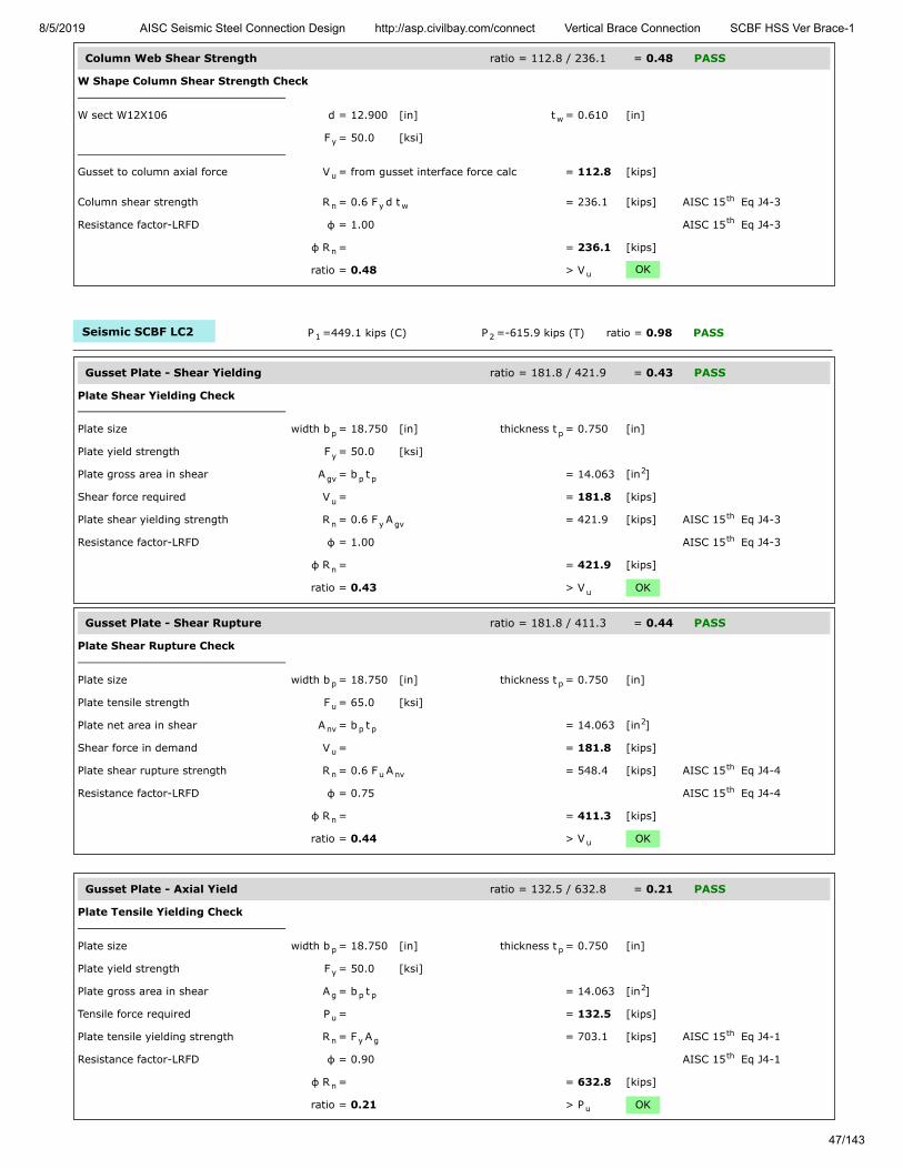
8/5/2019 AISC Seismic Steel Connection Design http://asp.civilbay.com/connect Vertical Brace Connection SCBF HSS Ver Brace-1
47/143
Column Web Shear Strength ratio = 112.8 / 236.1 = 0.48 PASS
W Shape Column Shear Strength Check
W sect W12X106 d = 12.900 [in] t = 0.610 [in]
F = 50.0 [ksi]
Gusset to column axial force V = from gusset interface force calc = 112.8 [kips]
Column shear strength R = 0.6 F d t = 236.1 [kips] AISC 15 Eq J4-3
Resistance factor-LRFD φ = 1.00 AISC 15 Eq J4-3
φ R = = 236.1 [kips]
ratio = 0.48 > V OK
Seismic SCBF LC2 P =449.1 kips (C) P =-615.9 kips (T) ratio = 0.98 PASS
Gusset Plate - Shear Yielding ratio = 181.8 / 421.9 = 0.43 PASS
Plate Shear Yielding Check
Plate size width b = 18.750 [in] thickness t = 0.750 [in]
Plate yield strength F = 50.0 [ksi]
Plate gross area in shear A = b t = 14.063 [in ]
Shear force required V = = 181.8 [kips]
Plate shear yielding strength R = 0.6 F A = 421.9 [kips] AISC 15 Eq J4-3
Resistance factor-LRFD φ = 1.00 AISC 15 Eq J4-3
φ R = = 421.9 [kips]
ratio = 0.43 > V OK
Gusset Plate - Shear Rupture ratio = 181.8 / 411.3 = 0.44 PASS
Plate Shear Rupture Check
Plate size width b = 18.750 [in] thickness t = 0.750 [in]
Plate tensile strength F = 65.0 [ksi]
Plate net area in shear A = b t = 14.063 [in ]
Shear force in demand V = = 181.8 [kips]
Plate shear rupture strength R = 0.6 F A = 548.4 [kips] AISC 15 Eq J4-4
Resistance factor-LRFD φ = 0.75 AISC 15 Eq J4-4
φ R = = 411.3 [kips]
ratio = 0.44 > V OK
Gusset Plate - Axial Yield ratio = 132.5 / 632.8 = 0.21 PASS
Plate Tensile Yielding Check
Plate size width b = 18.750 [in] thickness t = 0.750 [in]
Plate yield strength F = 50.0 [ksi]
Plate gross area in shear A = b t = 14.063 [in ]
Tensile force required P = = 132.5 [kips]
Plate tensile yielding strength R = F A = 703.1 [kips] AISC 15 Eq J4-1
Resistance factor-LRFD φ = 0.90 AISC 15 Eq J4-1
φ R = = 632.8 [kips]
ratio = 0.21 > P OK
w
y
u
n y wth
th
n
u
1 2
p p
y
gv p p2
u
n y gvth
th
n
u
p p
u
nv p p2
u
n u nvth
th
n
u
p p
y
g p p2
u
n y gth
th
n
u
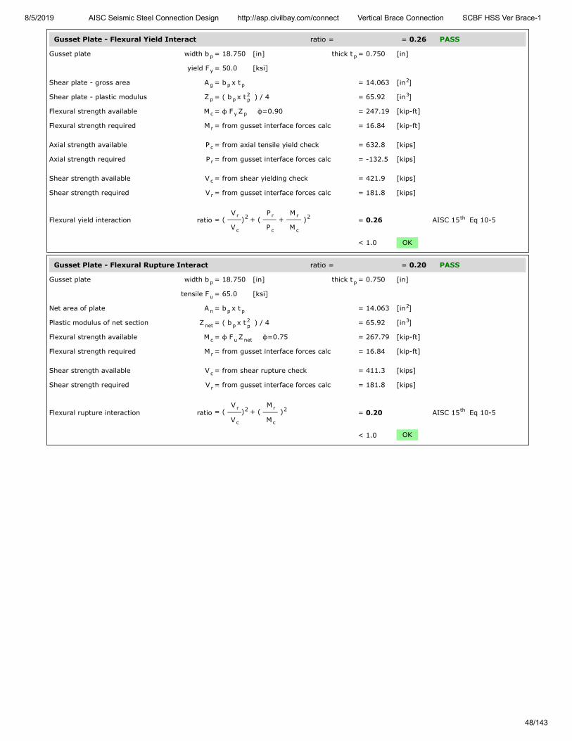
8/5/2019 AISC Seismic Steel Connection Design http://asp.civilbay.com/connect Vertical Brace Connection SCBF HSS Ver Brace-1
48/143
Gusset Plate - Flexural Yield Interact ratio = = 0.26 PASS
Gusset plate width b = 18.750 [in] thick t = 0.750 [in]
yield F = 50.0 [ksi]
Shear plate - gross area A = b x t = 14.063 [in ]
Shear plate - plastic modulus Z = ( b x t ) / 4 = 65.92 [in ]
Flexural strength available M = φ F Z φ=0.90 = 247.19 [kip-ft]
Flexural strength required M = from gusset interface forces calc = 16.84 [kip-ft]
Axial strength available P = from axial tensile yield check = 632.8 [kips]
Axial strength required P = from gusset interface forces calc = -132.5 [kips]
Shear strength available V = from shear yielding check = 421.9 [kips]
Shear strength required V = from gusset interface forces calc = 181.8 [kips]
Flexural yield interaction ratio = ( V
V) + (
P
P +
M
M ) = 0.26 AISC 15 Eq 10-5
< 1.0 OK
Gusset Plate - Flexural Rupture Interact ratio = = 0.20 PASS
Gusset plate width b = 18.750 [in] thick t = 0.750 [in]
tensile F = 65.0 [ksi]
Net area of plate A = b x t = 14.063 [in ]
Plastic modulus of net section Z = ( b x t ) / 4 = 65.92 [in ]
Flexural strength available M = φ F Z φ=0.75 = 267.79 [kip-ft]
Flexural strength required M = from gusset interface forces calc = 16.84 [kip-ft]
Shear strength available V = from shear rupture check = 411.3 [kips]
Shear strength required V = from gusset interface forces calc = 181.8 [kips]
Flexural rupture interaction ratio = ( V
V) + (
M
M ) = 0.20 AISC 15 Eq 10-5
< 1.0 OK
p p
y
g p p2
p p2p
3
c y p
r
c
r
c
r
r
c
2 r
c
r
c
2 th
p p
u
n p p2
net p2p
3
c u net
r
c
r
r
c
2 r
c
2 th

8/5/2019 AISC Seismic Steel Connection Design http://asp.civilbay.com/connect Vertical Brace Connection SCBF HSS Ver Brace-1
49/143
Gusset to Column Weld Strength ratio = 14.30 / 14.64 = 0.98 PASS
Gusset to Column Interface - Forces
shear V = 181.8 [kips] axial H = -132.5 [kips] in tension
moment M = 16.84 [kip-ft]
Gusset to Column Interface - Weld Length
Gusset-column fillet weld length L = from user input = 18.750 [in]
Gusset to Column Interface - Combined Weld Stress
Weld stress from axial force f = H / L = -7.067 [kip/in] in tension
Weld stress from shear force f = V / L = 9.696 [kip/in]
Weld stress from moment force f = M
L / 6 = 3.449 [kip/in]
Weld stress combined - max f = [ (f - f ) + f ] = 14.303 [kip/in] AISC 15 Eq 8-11
Weld resultant load angle θ = tan [( f - f ) / f ] = 47.3 [°]
Fillet Weld Strength Calc
Fillet weld leg size w = ⁄ [in] load angle θ = 47.3 [°]
Electrode strength F = 70.0 [ksi] strength coeff C = 1.00 AISC 15 Table 8-3
Number of weld line n = 2 for double fillet
Load angle coefficient C = ( 1 + 0.5 sin θ ) = 1.32 AISC 15 Page 8-9
Fillet weld shear strength R = 0.6 (C x 70 ksi) 0.707 w n C = 24.408 [kip/in] AISC 15 Eq 8-1
Base metal - gusset plate thickness t = 0.750 [in] tensile F = 65.0 [ksi]
Base metal - gusset plate is in shear, shear rupture as per AISC 15 Eq J4-4 is checked AISC 15 J2.4
Base metal shear rupture R = 0.6 F t = 29.250 [kip/in] AISC 15 Eq J4-4
Double fillet linear shear strength R = min ( R , R ) = 24.408 [kip/in] AISC 15 Eq 9-2
Resistance factor-LRFD φ = 0.75 AISC 15 Eq 8-1
φ R = = 18.306 [kip/in]
When gusset plate is directly welded to beam or column, apply 1.25 ductility factorto allow adequate force redistribution in the weld group AISC 15 Page 13-11
Weld strength used for design afterapplying ductility factor
φ R = φ R x ( 1/1.25 ) = 14.645 [kip/in]
ratio = 0.98 > f OK
c c
c
wc
a c wc
v c wc
b 2
max a b2 2
v0.5 th
-1b a v
516
EXX 1th
21.5 th
n-w 1 2th
u
th th
n-b uth
n n-w n-bth
th
n
th
n n
max

8/5/2019 AISC Seismic Steel Connection Design http://asp.civilbay.com/connect Vertical Brace Connection SCBF HSS Ver Brace-1
50/143
Column Web Local Yielding ratio = 175.6 / 814.4 = 0.22 PASS
Gusset Edge Equivalent Normal Force
Refer to AISC DG29 Fig. B-1 for formula below to calculate gusset edge equivalent normal force
Gusset edge axial force N = = -132.5 [kips]
Gusset edge moment force M = = 16.84 [kip-ft]
Gusset edge interface length L = = 18.750 [in]
Gusset edge equivalent normalforce
N = N - 4 ML = -175.6 [kips] AISC DG29 Fig B-1
Concentrated force from gusset P = = 175.6 [kips]
Column section d = 12.900 [in] t = 0.990 [in]
t = 0.610 [in] k = 1.590 [in]
yield F = 50.0 [ksi]
Length of bearing l = Gusset/Column interface length = 18.750 [in]
Column web local yielding strength R = F t ( 5 k + l ) = 814.4 [kips] AISC 15 Eq J10-2
Resistance factor-LRFD φ = 1.00
φ R = = 814.4 [kips]
ratio = 0.22 > P OK
Column Web Shear Strength ratio = 132.5 / 236.1 = 0.56 PASS
W Shape Column Shear Strength Check
W sect W12X106 d = 12.900 [in] t = 0.610 [in]
F = 50.0 [ksi]
Gusset to column axial force V = from gusset interface force calc = 132.5 [kips]
Column shear strength R = 0.6 F d t = 236.1 [kips] AISC 15 Eq J4-3
Resistance factor-LRFD φ = 1.00 AISC 15 Eq J4-3
φ R = = 236.1 [kips]
ratio = 0.56 > V OK
e
u
f
w
y
b
n y w bth
n
u
w
y
u
n y wth
th
n
u

8/5/2019 AISC Seismic Steel Connection Design http://asp.civilbay.com/connect Vertical Brace Connection SCBF HSS Ver Brace-1
51/143
Bot Brace - Gusset to Beam Direct Weld Connection Code=AISC 360-16 LRFD
Result Summary geometries & weld limitations = PASS limit states max ratio = 0.82 PASS
Brace Weld Limitation Checks - Gusset to Beam PASS
Min Fillet Weld Size
Thinner part joined thickness t = = 0.750 [in]
Min fillet weld size allowed w = = 0.250 [in] AISC 15 Table J2.4
Fillet weld size provided w = = 0.438 [in]
≥ w OK
Min Fillet Weld Length
Fillet weld size provided w = = 0.438 [in]
Min fillet weld length allowed L = 4 x w = 1.750 [in] AISC 15 J2.2b
Min fillet weld length L = = 27.500 [in]
≥ L OK
Seismic SCBF LC1 P =-559.7 kips (T) P =524.4 kips (C) ratio = 0.60 PASS
Gusset Plate - Shear Yielding ratio = 258.0 / 618.8 = 0.42 PASS
Plate Shear Yielding Check
Plate size width b = 27.500 [in] thickness t = 0.750 [in]
Plate yield strength F = 50.0 [ksi]
Plate gross area in shear A = b t = 20.625 [in ]
Shear force required V = = 258.0 [kips]
Plate shear yielding strength R = 0.6 F A = 618.8 [kips] AISC 15 Eq J4-3
Resistance factor-LRFD φ = 1.00 AISC 15 Eq J4-3
φ R = = 618.8 [kips]
ratio = 0.42 > V OK
Gusset Plate - Shear Rupture ratio = 258.0 / 603.3 = 0.43 PASS
Plate Shear Rupture Check
Plate size width b = 27.500 [in] thickness t = 0.750 [in]
Plate tensile strength F = 65.0 [ksi]
Plate net area in shear A = b t = 20.625 [in ]
Shear force in demand V = = 258.0 [kips]
Plate shear rupture strength R = 0.6 F A = 804.4 [kips] AISC 15 Eq J4-4
Resistance factor-LRFD φ = 0.75 AISC 15 Eq J4-4
φ R = = 603.3 [kips]
ratio = 0.43 > V OK
minth
min
minth
min
1 2
p p
y
gv p p2
u
n y gvth
th
n
u
p p
u
nv p p2
u
n u nvth
th
n
u

8/5/2019 AISC Seismic Steel Connection Design http://asp.civilbay.com/connect Vertical Brace Connection SCBF HSS Ver Brace-1
52/143
Gusset Plate - Axial Tensile Yield ratio = 216.0 / 928.1 = 0.23 PASS
Plate Tensile Yielding Check
Plate size width b = 27.500 [in] thickness t = 0.750 [in]
Plate yield strength F = 50.0 [ksi]
Plate gross area in shear A = b t = 20.625 [in ]
Tensile force required P = = 216.0 [kips]
Plate tensile yielding strength R = F A = 1031.3 [kips] AISC 15 Eq J4-1
Resistance factor-LRFD φ = 0.90 AISC 15 Eq J4-1
φ R = = 928.1 [kips]
ratio = 0.23 > P OK
Gusset Plate - Flexural Yield Interact ratio = = 0.23 PASS
Gusset plate width b = 27.500 [in] thick t = 0.750 [in]
yield F = 50.0 [ksi]
Shear plate - gross area A = b x t = 20.625 [in ]
Shear plate - plastic modulus Z = ( b x t ) / 4 = 141.80 [in ]
Flexural strength available M = φ F Z φ=0.90 = 531.74 [kip-ft]
Flexural strength required M = from gusset interface forces calc = 0.00 [kip-ft]
Axial strength available P = from axial tensile yield check = 928.1 [kips]
Axial strength required P = from gusset interface forces calc = 216.0 [kips]
Shear strength available V = from shear yielding check = 618.8 [kips]
Shear strength required V = from gusset interface forces calc = 258.0 [kips]
Flexural yield interaction ratio = ( V
V) + (
P
P +
M
M ) = 0.23 AISC 15 Eq 10-5
< 1.0 OK
Gusset Plate - Flexural Rupture Interact ratio = = 0.18 PASS
Gusset plate width b = 27.500 [in] thick t = 0.750 [in]
tensile F = 65.0 [ksi]
Net area of plate A = b x t = 20.625 [in ]
Plastic modulus of net section Z = ( b x t ) / 4 = 141.80 [in ]
Flexural strength available M = φ F Z φ=0.75 = 576.05 [kip-ft]
Flexural strength required M = from gusset interface forces calc = 0.00 [kip-ft]
Shear strength available V = from shear rupture check = 603.3 [kips]
Shear strength required V = from gusset interface forces calc = 258.0 [kips]
Flexural rupture interaction ratio = ( V
V) + (
M
M ) = 0.18 AISC 15 Eq 10-5
< 1.0 OK
p p
y
g p p2
u
n y gth
th
n
u
p p
y
g p p2
p p2p
3
c y p
r
c
r
c
r
r
c
2 r
c
r
c
2 th
p p
u
n p p2
net p2p
3
c u net
r
c
r
r
c
2 r
c
2 th
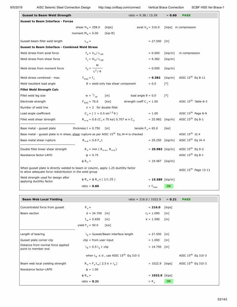
8/5/2019 AISC Seismic Steel Connection Design http://asp.civilbay.com/connect Vertical Brace Connection SCBF HSS Ver Brace-1
53/143
Gusset to Beam Weld Strength ratio = 9.38 / 15.59 = 0.60 PASS
Gusset to Beam Interface - Forces
shear H = 258.0 [kips] axial V = 216.0 [kips] in compression
moment M = 0.00 [kip-ft]
Gusset-beam fillet weld length L = = 27.500 [in]
Gusset to Beam Interface - Combined Weld Stress
Weld stress from axial force f = V / L = 0.000 [kip/in] in compression
Weld stress from shear force f = H / L = 9.382 [kip/in]
Weld stress from moment force f = M
L / 6 = 0.000 [kip/in]
Weld stress combined - max f = f = 9.382 [kip/in] AISC 15 Eq 8-11
Weld resultant load angle θ = weld only has shear component = 0.0 [°]
Fillet Weld Strength Calc
Fillet weld leg size w = ⁄ [in] load angle θ = 0.0 [°]
Electrode strength F = 70.0 [ksi] strength coeff C = 1.00 AISC 15 Table 8-3
Number of weld line n = 2 for double fillet
Load angle coefficient C = ( 1 + 0.5 sin θ ) = 1.00 AISC 15 Page 8-9
Fillet weld shear strength R = 0.6 (C x 70 ksi) 0.707 w n C = 25.982 [kip/in] AISC 15 Eq 8-1
Base metal - gusset plate thickness t = 0.750 [in] tensile F = 65.0 [ksi]
Base metal - gusset plate is in shear, shear rupture as per AISC 15 Eq J4-4 is checked AISC 15 J2.4
Base metal shear rupture R = 0.6 F t = 29.250 [kip/in] AISC 15 Eq J4-4
Double fillet linear shear strength R = min ( R , R ) = 25.982 [kip/in] AISC 15 Eq 9-2
Resistance factor-LRFD φ = 0.75 AISC 15 Eq 8-1
φ R = = 19.487 [kip/in]
When gusset plate is directly welded to beam or column, apply 1.25 ductility factorto allow adequate force redistribution in the weld group AISC 15 Page 13-11
Weld strength used for design afterapplying ductility factor
φ R = φ R x ( 1/1.25 ) = 15.589 [kip/in]
ratio = 0.60 > f OK
Beam Web Local Yielding ratio = 216.0 / 1022.9 = 0.21 PASS
Concentrated force from gusset P = = 216.0 [kips]
Beam section d = 24.700 [in] t = 1.090 [in]
t = 0.650 [in] k = 1.590 [in]
yield F = 50.0 [ksi]
Length of bearing l = Gusset/Beam interface length = 27.500 [in]
Gusset plate corner clip clip = from user input = 1.000 [in]
Distance from normal force appliedpoint to member end
l = 0.5 l + clip = 14.750 [in]
when l ≤ d , use AISC 15 Eq J10-3 AISC 15 Eq J10-3
Beam web local yielding strength R = F t ( 2.5 k + l ) = 1022.9 [kips] AISC 15 Eq J10-3
Resistance factor-LRFD φ = 1.00
φ R = = 1022.9 [kips]
ratio = 0.21 > P OK
b b
b
w
a b wb
v b wb
b 2
max vth
716
EXX 1th
21.5 th
n-w 1 2th
u
th th
n-b uth
n n-w n-bth
th
n
th
n n
max
u
f
w
y
b
N b
Nth th
n y w bth
n
u
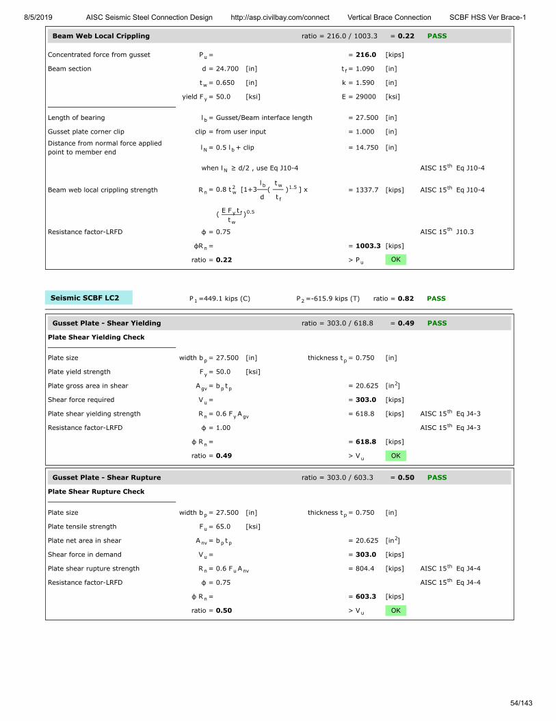
8/5/2019 AISC Seismic Steel Connection Design http://asp.civilbay.com/connect Vertical Brace Connection SCBF HSS Ver Brace-1
54/143
Beam Web Local Crippling ratio = 216.0 / 1003.3 = 0.22 PASS
Concentrated force from gusset P = = 216.0 [kips]
Beam section d = 24.700 [in] t = 1.090 [in]
t = 0.650 [in] k = 1.590 [in]
yield F = 50.0 [ksi] E = 29000 [ksi]
Length of bearing l = Gusset/Beam interface length = 27.500 [in]
Gusset plate corner clip clip = from user input = 1.000 [in]
Distance from normal force appliedpoint to member end
l = 0.5 l + clip = 14.750 [in]
when l ≥ d/2 , use Eq J10-4 AISC 15 Eq J10-4
Beam web local crippling strength R = 0.8 t [1+3l
d(
t
t ) ] x = 1337.7 [kips] AISC 15 Eq J10-4
( E F tt
)
Resistance factor-LRFD φ = 0.75 AISC 15 J10.3
φR = = 1003.3 [kips]
ratio = 0.22 > P OK
Seismic SCBF LC2 P =449.1 kips (C) P =-615.9 kips (T) ratio = 0.82 PASS
Gusset Plate - Shear Yielding ratio = 303.0 / 618.8 = 0.49 PASS
Plate Shear Yielding Check
Plate size width b = 27.500 [in] thickness t = 0.750 [in]
Plate yield strength F = 50.0 [ksi]
Plate gross area in shear A = b t = 20.625 [in ]
Shear force required V = = 303.0 [kips]
Plate shear yielding strength R = 0.6 F A = 618.8 [kips] AISC 15 Eq J4-3
Resistance factor-LRFD φ = 1.00 AISC 15 Eq J4-3
φ R = = 618.8 [kips]
ratio = 0.49 > V OK
Gusset Plate - Shear Rupture ratio = 303.0 / 603.3 = 0.50 PASS
Plate Shear Rupture Check
Plate size width b = 27.500 [in] thickness t = 0.750 [in]
Plate tensile strength F = 65.0 [ksi]
Plate net area in shear A = b t = 20.625 [in ]
Shear force in demand V = = 303.0 [kips]
Plate shear rupture strength R = 0.6 F A = 804.4 [kips] AISC 15 Eq J4-4
Resistance factor-LRFD φ = 0.75 AISC 15 Eq J4-4
φ R = = 603.3 [kips]
ratio = 0.50 > V OK
u
f
w
y
b
N b
Nth
n2w
b w
f
1.5 th
y f
w
0.5
th
n
u
1 2
p p
y
gv p p2
u
n y gvth
th
n
u
p p
u
nv p p2
u
n u nvth
th
n
u

8/5/2019 AISC Seismic Steel Connection Design http://asp.civilbay.com/connect Vertical Brace Connection SCBF HSS Ver Brace-1
55/143
Gusset Plate - Axial Yield ratio = 253.7 / 928.1 = 0.27 PASS
Plate Tensile Yielding Check
Plate size width b = 27.500 [in] thickness t = 0.750 [in]
Plate yield strength F = 50.0 [ksi]
Plate gross area in shear A = b t = 20.625 [in ]
Tensile force required P = = 253.7 [kips]
Plate tensile yielding strength R = F A = 1031.3 [kips] AISC 15 Eq J4-1
Resistance factor-LRFD φ = 0.90 AISC 15 Eq J4-1
φ R = = 928.1 [kips]
ratio = 0.27 > P OK
Gusset Plate - Axial Tensile Rupture ratio = 253.7 / 1005.5 = 0.25 PASS
Plate Tensile Rupture Check
Plate size width b = 27.500 [in] thickness t = 0.750 [in]
Plate tensile strength F = 65.0 [ksi]
Plate net area in tension A = b t = 20.625 [in ]
Tensile force required P = = 253.7 [kips]
Plate tensile rupture strength R = F A = 1340.6 [kips] AISC 15 Eq J4-2
Resistance factor-LRFD φ = 0.75 AISC 15 Eq J4-2
φ R = = 1005.5 [kips] AISC 15 Eq J4-2
ratio = 0.25 > P OK
Gusset Plate - Flexural Yield Interact ratio = = 0.31 PASS
Gusset plate width b = 27.500 [in] thick t = 0.750 [in]
yield F = 50.0 [ksi]
Shear plate - gross area A = b x t = 20.625 [in ]
Shear plate - plastic modulus Z = ( b x t ) / 4 = 141.80 [in ]
Flexural strength available M = φ F Z φ=0.90 = 531.74 [kip-ft]
Flexural strength required M = from gusset interface forces calc = 0.00 [kip-ft]
Axial strength available P = from axial tensile yield check = 928.1 [kips]
Axial strength required P = from gusset interface forces calc = -253.7 [kips]
Shear strength available V = from shear yielding check = 618.8 [kips]
Shear strength required V = from gusset interface forces calc = 303.0 [kips]
Flexural yield interaction ratio = ( V
V) + (
P
P +
M
M ) = 0.31 AISC 15 Eq 10-5
< 1.0 OK
p p
y
g p p2
u
n y gth
th
n
u
p p
u
nt p p2
u
n u ntth
th
nth
u
p p
y
g p p2
p p2p
3
c y p
r
c
r
c
r
r
c
2 r
c
r
c
2 th
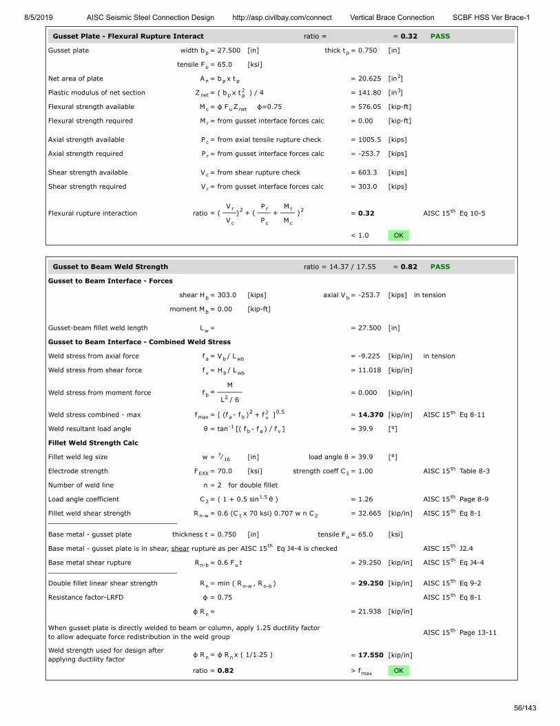
8/5/2019 AISC Seismic Steel Connection Design http://asp.civilbay.com/connect Vertical Brace Connection SCBF HSS Ver Brace-1
56/143
Gusset Plate - Flexural Rupture Interact ratio = = 0.32 PASS
Gusset plate width b = 27.500 [in] thick t = 0.750 [in]
tensile F = 65.0 [ksi]
Net area of plate A = b x t = 20.625 [in ]
Plastic modulus of net section Z = ( b x t ) / 4 = 141.80 [in ]
Flexural strength available M = φ F Z φ=0.75 = 576.05 [kip-ft]
Flexural strength required M = from gusset interface forces calc = 0.00 [kip-ft]
Axial strength available P = from axial tensile rupture check = 1005.5 [kips]
Axial strength required P = from gusset interface forces calc = -253.7 [kips]
Shear strength available V = from shear rupture check = 603.3 [kips]
Shear strength required V = from gusset interface forces calc = 303.0 [kips]
Flexural rupture interaction ratio = ( V
V) + (
P
P +
M
M ) = 0.32 AISC 15 Eq 10-5
< 1.0 OK
Gusset to Beam Weld Strength ratio = 14.37 / 17.55 = 0.82 PASS
Gusset to Beam Interface - Forces
shear H = 303.0 [kips] axial V = -253.7 [kips] in tension
moment M = 0.00 [kip-ft]
Gusset-beam fillet weld length L = = 27.500 [in]
Gusset to Beam Interface - Combined Weld Stress
Weld stress from axial force f = V / L = -9.225 [kip/in] in tension
Weld stress from shear force f = H / L = 11.018 [kip/in]
Weld stress from moment force f = M
L / 6 = 0.000 [kip/in]
Weld stress combined - max f = [ (f - f ) + f ] = 14.370 [kip/in] AISC 15 Eq 8-11
Weld resultant load angle θ = tan [( f - f ) / f ] = 39.9 [°]
Fillet Weld Strength Calc
Fillet weld leg size w = ⁄ [in] load angle θ = 39.9 [°]
Electrode strength F = 70.0 [ksi] strength coeff C = 1.00 AISC 15 Table 8-3
Number of weld line n = 2 for double fillet
Load angle coefficient C = ( 1 + 0.5 sin θ ) = 1.26 AISC 15 Page 8-9
Fillet weld shear strength R = 0.6 (C x 70 ksi) 0.707 w n C = 32.665 [kip/in] AISC 15 Eq 8-1
Base metal - gusset plate thickness t = 0.750 [in] tensile F = 65.0 [ksi]
Base metal - gusset plate is in shear, shear rupture as per AISC 15 Eq J4-4 is checked AISC 15 J2.4
Base metal shear rupture R = 0.6 F t = 29.250 [kip/in] AISC 15 Eq J4-4
Double fillet linear shear strength R = min ( R , R ) = 29.250 [kip/in] AISC 15 Eq 9-2
Resistance factor-LRFD φ = 0.75 AISC 15 Eq 8-1
φ R = = 21.938 [kip/in]
When gusset plate is directly welded to beam or column, apply 1.25 ductility factorto allow adequate force redistribution in the weld group AISC 15 Page 13-11
Weld strength used for design afterapplying ductility factor
φ R = φ R x ( 1/1.25 ) = 17.550 [kip/in]
ratio = 0.82 > f OK
p p
u
n p p2
net p2p
3
c u net
r
c
r
c
r
r
c
2 r
c
r
c
2 th
b b
b
w
a b wb
v b wb
b 2
max a b2 2
v0.5 th
-1b a v
716
EXX 1th
21.5 th
n-w 1 2th
u
th th
n-b uth
n n-w n-bth
th
n
th
n n
max
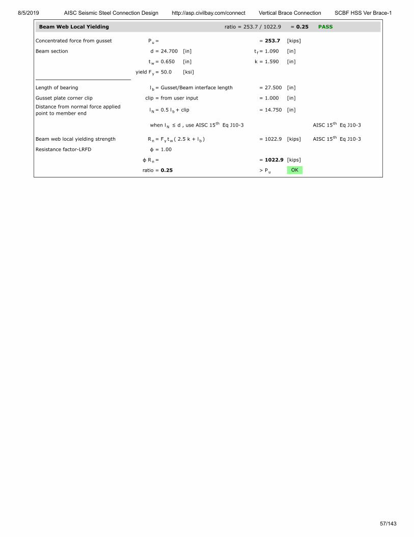
8/5/2019 AISC Seismic Steel Connection Design http://asp.civilbay.com/connect Vertical Brace Connection SCBF HSS Ver Brace-1
57/143
Beam Web Local Yielding ratio = 253.7 / 1022.9 = 0.25 PASS
Concentrated force from gusset P = = 253.7 [kips]
Beam section d = 24.700 [in] t = 1.090 [in]
t = 0.650 [in] k = 1.590 [in]
yield F = 50.0 [ksi]
Length of bearing l = Gusset/Beam interface length = 27.500 [in]
Gusset plate corner clip clip = from user input = 1.000 [in]
Distance from normal force appliedpoint to member end
l = 0.5 l + clip = 14.750 [in]
when l ≤ d , use AISC 15 Eq J10-3 AISC 15 Eq J10-3
Beam web local yielding strength R = F t ( 2.5 k + l ) = 1022.9 [kips] AISC 15 Eq J10-3
Resistance factor-LRFD φ = 1.00
φ R = = 1022.9 [kips]
ratio = 0.25 > P OK
u
f
w
y
b
N b
Nth th
n y w bth
n
u

8/5/2019 AISC Seismic Steel Connection Design http://asp.civilbay.com/connect Vertical Brace Connection SCBF HSS Ver Brace-1
58/143
Beam to Column Direct Weld Connection Code=AISC 360-16 LRFD
Result Summary geometries & weld limitations = PASS limit states max ratio = 0.97 PASS
Beam Flange Fillet Weld Limitation PASS
Min Fillet Weld Size
Thinner part joined thickness t = = 0.990 [in]
Min fillet weld size allowed w = = 0.313 [in] AISC 15 Table J2.4
Fillet weld size provided w = = 0.313 [in]
≥ w OK
Min Fillet Weld Length
Fillet weld size provided w = = 0.313 [in]
Min fillet weld length allowed L = 4 x w = 1.250 [in] AISC 15 J2.2b
Min fillet weld length L = 0.5 b - k = 4.975 [in]
≥ L OK
Beam Web Fillet Weld Limitation PASS
Min Fillet Weld Size
Thinner part joined thickness t = = 0.650 [in]
Min fillet weld size allowed w = = 0.250 [in] AISC 15 Table J2.4
Fillet weld size provided w = = 0.563 [in]
≥ w OK
Min Fillet Weld Length
Fillet weld size provided w = = 0.563 [in]
Min fillet weld length allowed L = 4 x w = 2.250 [in] AISC 15 J2.2b
Min fillet weld length L = d - 2 k = 20.700 [in]
≥ L OK
Seismic SCBF LC1 shear V = 435.1 kips axial P = 58.3 kips (C) ratio = 0.90 PASS
Beam to Column - Beam Shear ratio = 435.1 / 481.7 = 0.90 PASS
W Shape Beam Shear Yielding Check
W sect W24X146 d = 24.700 [in] t = 0.650 [in]
F = 50.0 [ksi]
Beam to column shear V = from gusset interface force calc = 435.1 [kips]
Beam shear strength R = 0.6 F d t = 481.7 [kips] AISC 15 Eq J4-3
Resistance factor-LRFD φ = 1.00 AISC 15 Eq J4-3
φ R = = 481.7 [kips]
ratio = 0.90 > V OK
minth
min
minth
fb 1b
min
minth
min
minth
b b
min
w
y
u
n y wth
th
n
u

8/5/2019 AISC Seismic Steel Connection Design http://asp.civilbay.com/connect Vertical Brace Connection SCBF HSS Ver Brace-1
59/143
Beam to Column - Beam Stub Compressive Strength ratio = 58.3 / 1935.0 = 0.03 PASS
W Shape Compression Check
W sect W24X146 A = 43.000 [in ] r = 3.022 [in]
F = 50.0 [ksi]
W sect effective length factor K = = 1.00
W sect unbraced length L = = 30.000 [in]
W sect slenderness KL/r = 1.00 x L / r = 9.93
Compression force on W sect P = = 58.3 [kips]
when KL
r ≤ 25 AISC 15 J4.4 (a)
W sect compression provided R = F x A = 2150.0 [kips] AISC 15 Eq J4-6
Resistance factor-LRFD φ = 0.90 AISC 15 J4.4 (a)
φ R = = 1935.0 [kips]
ratio = 0.03 > P OK
Beam W Shape Axial Force Distribution
W Shape Beam Axial Force Distribution
W sect W24X146 d = 24.700 [in] b = 12.900 [in]
t = 1.090 [in] t = 0.650 [in]
A = 43.000 [in ]
W shape one side flange area A = b t = 14.061 [in ]
W shape web area A = A- 2 A = 14.878 [in ]
W shape axial force P = = 58.3 [kips]
Axial force on flange P = AA
P = 19.1 [kips]
Axial force on web P = AA
P = 20.2 [kips]
Beam to Column - W Shape Flange Weld ratio = NA = 0.00 PASS
Beam flange tensile force P = from beam axial force distribution calc = 19.1 [kips]
Beam flange force is in compression, the flange weld check is not needed
2y
y
y
u
th
n yth
th
n
u
f
f w
2
f f f2
w f2
ff
ww
u

8/5/2019 AISC Seismic Steel Connection Design http://asp.civilbay.com/connect Vertical Brace Connection SCBF HSS Ver Brace-1
60/143
Beam to Column - W Shape Web Weld ratio = 21.02 / 25.05 = 0.84 PASS
Beam section W24X146 d = 24.700 [in] k = 2.000 [in]
Fillet weld length on beam web L = d - 2 k = 20.700 [in]
Weld Group Forces
Weld group forces shear V = 435.1 [kips] axial P = 20.2 [kips] in compression
Beam web fillet weld size w = = 0.563 [in]
Combined Weld Stress
Weld stress from axial force f = P / L = 0.000 [kip/in] in compression
Weld stress from shear force f = V / L = 21.019 [kip/in]
Weld stress combined - max f = f = 21.019 [kip/in] AISC 15 Eq 8-11
Weld stress load angle θ = = 0.0 [°]
Fillet Weld Strength Calc
Fillet weld leg size w = ⁄ [in] load angle θ = 0.0 [°]
Electrode strength F = 70.0 [ksi] strength coeff C = 1.00 AISC 15 Table 8-3
Number of weld line n = 2 for double fillet
Load angle coefficient C = ( 1 + 0.5 sin θ ) = 1.00 AISC 15 Page 8-9
Fillet weld shear strength R = 0.6 (C x 70 ksi) 0.707 w n C = 33.406 [kip/in] AISC 15 Eq 8-1
Base metal - beam web thickness t = 0.650 [in] tensile F = 65.0 [ksi]
Base metal - beam web is in tension, tensile rupture as per AISC 15 Eq J4-2 is checked AISC 15 J2.4
Base metal tensile rupture R = F t = 42.250 [kip/in] AISC 15 Eq J4-2
Double fillet linear shear strength R = min ( R , R ) = 33.406 [kip/in] AISC 15 Eq 9-2
Resistance factor-LRFD φ = 0.75 AISC 15 Eq 8-1
φ R = = 25.054 [kip/in]
ratio = 0.84 > f OK
Column Web Local Yielding - Beam Flange ratio = 19.1 / 275.7 = 0.07 PASS
Column Web Local Yielding at Beam Flange Location
Column sect W12X106 k = 1.590 [in] t = 0.610 [in]
F = 50.0 [ksi]
Beam section W24X146 t = 1.090 [in]
Beam flange force P = from beam axial force distribution calc = 19.1 [kips]
Column web local yielding strength R = F t (5 k + t ) = 275.7 [kips] AISC 15 Eq 4-2
Resistance factor-LRFD φ = 1.00 AISC 15 Eq 4-2
φ R = = 275.7 [kips]
ratio = 0.07 > P OK
b b
b b
a
v
max vth
916
EXX 1th
21.5 th
n-w 1 2th
u
th th
n-b uth
n n-w n-bth
th
n
max
c wc
yc
fb
u
n yc wc c fbth
th
n
u

8/5/2019 AISC Seismic Steel Connection Design http://asp.civilbay.com/connect Vertical Brace Connection SCBF HSS Ver Brace-1
61/143
Column Web Local Yielding - Beam Web ratio = 20.2 / 631.4 = 0.03 PASS
Column Web Local Yielding at Beam Web Location
Column sect W12X106 k = 1.590 [in] t = 0.610 [in]
F = 50.0 [ksi]
Beam section W24X146 T = 20.700 [in]
Beam axial force on beam web P = from beam axial force distribution calc = 20.2 [kips]
Column web local yielding strength R = F t T = 631.4 [kips] AISC 15 Eq J10-2
Resistance factor-LRFD φ = 1.00 AISC 15 J10.2
φ R = = 631.4 [kips]
ratio = 0.03 > P OK
Column Web Local Crippling - Beam Web ratio = 58.3 / 1139.9 = 0.05 PASS
Column Web Local Crippling at Beam Web Location
Column sect W12X106 d = 12.900 [in] t = 0.990 [in]
t = 0.610 [in]
F = 50.0 [ksi] E = 29000 [ksi]
Beam section W24X146 T = 20.700 [in]
Beam web compression force P = from beam axial force distribution calc = 58.3 [kips]
Column web local crippling strength R = 0.8 t [1+3 Td
( tt
) ] x = 1519.9 [kips] AISC 15 Eq J10-4
( E F tt
)
Resistance factor-LRFD φ = 0.75 AISC 15 J10.3
φR = = 1139.9 [kips]
ratio = 0.05 > P OK
Seismic SCBF LC2 shear V = 465.4 kips axial P = 78.6 kips (C) ratio = 0.97 PASS
Beam to Column - Beam Shear ratio = 465.4 / 481.7 = 0.97 PASS
W Shape Beam Shear Yielding Check
W sect W24X146 d = 24.700 [in] t = 0.650 [in]
F = 50.0 [ksi]
Beam to column shear V = from gusset interface force calc = 465.4 [kips]
Beam shear strength R = 0.6 F d t = 481.7 [kips] AISC 15 Eq J4-3
Resistance factor-LRFD φ = 1.00 AISC 15 Eq J4-3
φ R = = 481.7 [kips]
ratio = 0.97 > V OK
c wc
yc
b
u
n yc wc bth
th
n
u
c fc
wc
yc
b
u
n2wc
b
c
wc
fc
1.5 th
cy fc
wc
0.5
th
n
u
w
y
u
n y wth
th
n
u
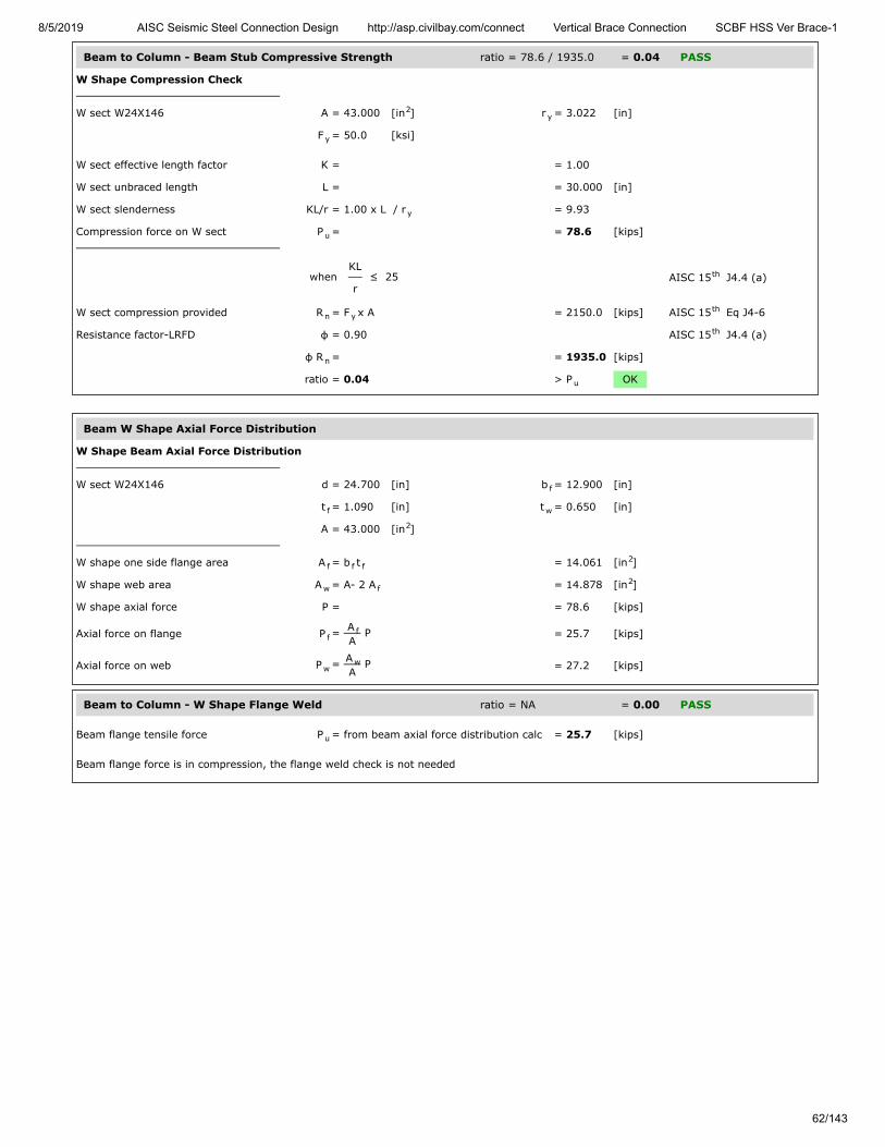
8/5/2019 AISC Seismic Steel Connection Design http://asp.civilbay.com/connect Vertical Brace Connection SCBF HSS Ver Brace-1
62/143
Beam to Column - Beam Stub Compressive Strength ratio = 78.6 / 1935.0 = 0.04 PASS
W Shape Compression Check
W sect W24X146 A = 43.000 [in ] r = 3.022 [in]
F = 50.0 [ksi]
W sect effective length factor K = = 1.00
W sect unbraced length L = = 30.000 [in]
W sect slenderness KL/r = 1.00 x L / r = 9.93
Compression force on W sect P = = 78.6 [kips]
when KL
r ≤ 25 AISC 15 J4.4 (a)
W sect compression provided R = F x A = 2150.0 [kips] AISC 15 Eq J4-6
Resistance factor-LRFD φ = 0.90 AISC 15 J4.4 (a)
φ R = = 1935.0 [kips]
ratio = 0.04 > P OK
Beam W Shape Axial Force Distribution
W Shape Beam Axial Force Distribution
W sect W24X146 d = 24.700 [in] b = 12.900 [in]
t = 1.090 [in] t = 0.650 [in]
A = 43.000 [in ]
W shape one side flange area A = b t = 14.061 [in ]
W shape web area A = A- 2 A = 14.878 [in ]
W shape axial force P = = 78.6 [kips]
Axial force on flange P = AA
P = 25.7 [kips]
Axial force on web P = AA
P = 27.2 [kips]
Beam to Column - W Shape Flange Weld ratio = NA = 0.00 PASS
Beam flange tensile force P = from beam axial force distribution calc = 25.7 [kips]
Beam flange force is in compression, the flange weld check is not needed
2y
y
y
u
th
n yth
th
n
u
f
f w
2
f f f2
w f2
ff
ww
u

8/5/2019 AISC Seismic Steel Connection Design http://asp.civilbay.com/connect Vertical Brace Connection SCBF HSS Ver Brace-1
63/143
Beam to Column - W Shape Web Weld ratio = 22.48 / 25.05 = 0.90 PASS
Beam section W24X146 d = 24.700 [in] k = 2.000 [in]
Fillet weld length on beam web L = d - 2 k = 20.700 [in]
Weld Group Forces
Weld group forces shear V = 465.4 [kips] axial P = 27.2 [kips] in compression
Beam web fillet weld size w = = 0.563 [in]
Combined Weld Stress
Weld stress from axial force f = P / L = 0.000 [kip/in] in compression
Weld stress from shear force f = V / L = 22.483 [kip/in]
Weld stress combined - max f = f = 22.483 [kip/in] AISC 15 Eq 8-11
Weld stress load angle θ = = 0.0 [°]
Fillet Weld Strength Calc
Fillet weld leg size w = ⁄ [in] load angle θ = 0.0 [°]
Electrode strength F = 70.0 [ksi] strength coeff C = 1.00 AISC 15 Table 8-3
Number of weld line n = 2 for double fillet
Load angle coefficient C = ( 1 + 0.5 sin θ ) = 1.00 AISC 15 Page 8-9
Fillet weld shear strength R = 0.6 (C x 70 ksi) 0.707 w n C = 33.406 [kip/in] AISC 15 Eq 8-1
Base metal - beam web thickness t = 0.650 [in] tensile F = 65.0 [ksi]
Base metal - beam web is in tension, tensile rupture as per AISC 15 Eq J4-2 is checked AISC 15 J2.4
Base metal tensile rupture R = F t = 42.250 [kip/in] AISC 15 Eq J4-2
Double fillet linear shear strength R = min ( R , R ) = 33.406 [kip/in] AISC 15 Eq 9-2
Resistance factor-LRFD φ = 0.75 AISC 15 Eq 8-1
φ R = = 25.054 [kip/in]
ratio = 0.90 > f OK
Column Web Local Yielding - Beam Flange ratio = 25.7 / 275.7 = 0.09 PASS
Column Web Local Yielding at Beam Flange Location
Column sect W12X106 k = 1.590 [in] t = 0.610 [in]
F = 50.0 [ksi]
Beam section W24X146 t = 1.090 [in]
Beam flange force P = from beam axial force distribution calc = 25.7 [kips]
Column web local yielding strength R = F t (5 k + t ) = 275.7 [kips] AISC 15 Eq 4-2
Resistance factor-LRFD φ = 1.00 AISC 15 Eq 4-2
φ R = = 275.7 [kips]
ratio = 0.09 > P OK
b b
b b
a
v
max vth
916
EXX 1th
21.5 th
n-w 1 2th
u
th th
n-b uth
n n-w n-bth
th
n
max
c wc
yc
fb
u
n yc wc c fbth
th
n
u
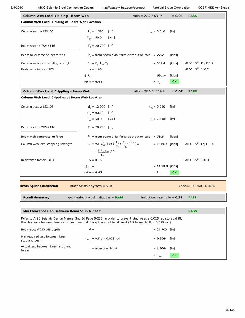
8/5/2019 AISC Seismic Steel Connection Design http://asp.civilbay.com/connect Vertical Brace Connection SCBF HSS Ver Brace-1
64/143
Column Web Local Yielding - Beam Web ratio = 27.2 / 631.4 = 0.04 PASS
Column Web Local Yielding at Beam Web Location
Column sect W12X106 k = 1.590 [in] t = 0.610 [in]
F = 50.0 [ksi]
Beam section W24X146 T = 20.700 [in]
Beam axial force on beam web P = from beam axial force distribution calc = 27.2 [kips]
Column web local yielding strength R = F t T = 631.4 [kips] AISC 15 Eq J10-2
Resistance factor-LRFD φ = 1.00 AISC 15 J10.2
φ R = = 631.4 [kips]
ratio = 0.04 > P OK
Column Web Local Crippling - Beam Web ratio = 78.6 / 1139.9 = 0.07 PASS
Column Web Local Crippling at Beam Web Location
Column sect W12X106 d = 12.900 [in] t = 0.990 [in]
t = 0.610 [in]
F = 50.0 [ksi] E = 29000 [ksi]
Beam section W24X146 T = 20.700 [in]
Beam web compression force P = from beam axial force distribution calc = 78.6 [kips]
Column web local crippling strength R = 0.8 t [1+3 Td
( tt
) ] x = 1519.9 [kips] AISC 15 Eq J10-4
( E F tt
)
Resistance factor-LRFD φ = 0.75 AISC 15 J10.3
φR = = 1139.9 [kips]
ratio = 0.07 > P OK
Beam Splice Calculation Brace Seismic System = SCBF Code=AISC 360-16 LRFD
Result Summary geometries & weld limitations = PASS limit states max ratio = 0.28 PASS
Min Clearance Gap Between Beam Stub & Beam PASS
Refer to AISC Seismic Design Manual 2nd Ed Page 5-235, in order to prevent binding at a 0.025 rad storey drift,the clearance between beam stub and beam at the splice must be at least (0.5 beam depth x 0.025 rad)
Beam sect W24X146 depth d = = 24.700 [in]
Min required gap between beamstub and beam
c = 0.5 d x 0.025 rad = 0.309 [in]
Actual gap between beam stub andbeam
c = from user input = 1.000 [in]
≥ c OK
c wc
yc
b
u
n yc wc bth
th
n
u
c fc
wc
yc
b
u
n2wc
b
c
wc
fc
1.5 th
cy fc
wc
0.5
th
n
u
min
min
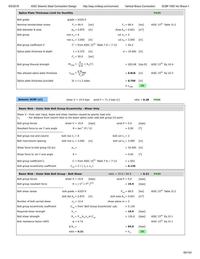
8/5/2019 AISC Seismic Steel Connection Design http://asp.civilbay.com/connect Vertical Brace Connection SCBF HSS Ver Brace-1
65/143
Splice Plate Thickness Limit for Ductility PASS
Bolt grade grade = A325-X
Nominal tensile/shear stress F = 90.0 [ksi] F = 68.0 [ksi] AISC 15 Table J3.2
Bolt diameter & area d = 0.875 [in] Area A = 0.601 [in ]
Bolt group row n = 6 col n = 2
row s = 3.000 [in] col s = 3.000 [in]
Bolt group coefficient C' C' = from AISC 15 Table 7-6 ~ 7-13 = 54.2
Splice plate thickness & depth t = 0.375 [in] d = 19.000 [in]
F = 50.0 [ksi]
Bolt group flexural strength M = F
0.9 ( A C') = 205.08 [kip-ft] AISC 15 Eq 10-4
Max allowed splice plate thickness t = 6 M
F d = 0.818 [in] AISC 15 Eq 10-3
Splice plate thickness provided 2t = t x 2 sides = 0.750 [in]
≤ t OK
Seismic SCBF LC1 shear V = 19.9 kips axial P = 71.3 kips (C) ratio = 0.28 PASS
Beam Web - Outer Side Bolt Group Eccentricity - Shear Only
Shear V - from user input, beam end shear reaction caused by gravity load onlye - hor distance from column face to the beam splice outer side bolt group CG point
Bolt group forces shear V = 19.9 [kips] axial P = 0.0 [kips]
Resultant force to ver Y axis angle θ = tan (P / V) = 0.00 [°]
Bolt group row and column bolt row n = 6 bolt col n = 2
Bolt row/column spacing bolt row s = 3.000 [in] bolt col s = 3.000 [in]
Shear force to bolt group CG ecc e = = 34.500 [in]
Shear force to ver Y axis angle θ = = 0.00 [°]
Bolt group coefficient C C = from AISC 15 Table 7-6 ~ 7-13 = 1.552
Bolt group eccentricity coefficient C = C / ( n x n ) = 0.129
Beam Web - Outer Side Bolt Group - Bolt Shear ratio = 19.9 / 94.9 = 0.21 PASS
Bolt group forces shear V = 19.9 [kips] axial P = 0.0 [kips]
Bolt group resultant force R = ( V + P ) = 19.9 [kips]
Bolt shear stress bolt grade = A325-X F = 68.0 [ksi] AISC 15 Table J3.2
bolt dia d = 0.875 [in] bolt area A = 0.601 [in ]
Number of bolt carried shear n = 12.0 shear plane m = 2
Bolt group eccentricity coefficient C = from 'Bolt Group Eccentricity' calc = 0.129
Required shear strength V = = 19.9 [kips]
Bolt shear strength R = F A n m C = 126.6 [kips] AISC 15 Eq J3-1
Bolt resistance factor-LRFD φ = 0.75 AISC 15 Eq J3-1
φ R = = 94.9 [kips]
ratio = 0.21 > V OK
t vth
b b2
v h
v h
th
y
maxv
bth
maxmax
y2
th
max
x
-1
r c
r c
x
th
ec r c
2 2 0.5
nvth
b b2
s
ec
u
n nv b s ecth
th
n
u

8/5/2019 AISC Seismic Steel Connection Design http://asp.civilbay.com/connect Vertical Brace Connection SCBF HSS Ver Brace-1
66/143
Beam Web - Outer Side Bolt Group - Bolt Bearing ratio = 19.9 / 94.9 = 0.21 PASS
The bolt group is oriented so that the shear force V is in ver. direction and the axial force P is in hor. direction
Bolt group forces shear V = 19.9 [kips] axial P = 0.0 [kips]
Bolt group resultant force R = ( V + P ) = 19.9 [kips]
Single Bolt Shear Strength
Bolt shear stress bolt grade = A325-X F = 68.0 [ksi] AISC 15 Table J3.2
bolt dia d = 0.875 [in] bolt area A = 0.601 [in ]
Single bolt shear strength R = 2 x F A = 81.8 [kips] AISC 15 Eq J3-1
Bolt Bearing/TearOut Strength on Plate
Bolt hole diameter bolt dia d = ⁄ [in] bolt hole dia d = ⁄ [in] AISC 15 Table J3.3
Bolt spacing spacing L = 3.000 [in]
Plate tensile strength F = 65.0 [ksi]
Plate thickness t = 0.650 [in]
Interior Bolt
Bolt hole edge clear distance L = L - d = 2.063 [in]
Bolt tear out/bearing strength R = 1.2 L t F ≤ 2.4 d t m F AISC 15 Eq J3-6a
= 104.6 ≤ 88.7 = 88.7 [kips]
Bolt strength at interior R = min ( R , R ) = 81.8 [kips]
Number of bolt interior n = 12
Bolt group eccentricity coefficient C = from calc in above section = 0.129
Bolt bearing strength for all bolts R = (n R ) C = 126.6 [kips]
Required shear strength V = = 19.9 [kips]
Bolt resistance factor-LRFD φ = 0.75 AISC 15 J3-10
φ R = = 94.9 [kips]
ratio = 0.21 > V OK
Beam Web - Inner Side Bolt Group Eccentricity - Shear Only
Shear V - from user input, beam end shear reaction caused by gravity load onlye - hor distance from column face to the beam splice inner side bolt group CG point
Bolt group forces shear V = 19.9 [kips] axial P = 0.0 [kips]
Resultant force to ver Y axis angle θ = tan (P / V) = 0.00 [°]
Bolt group row and column bolt row n = 6 bolt col n = 2
Bolt row/column spacing bolt row s = 3.000 [in] bolt col s = 3.000 [in]
Shear force to bolt group CG ecc e = = 26.500 [in]
Shear force to ver Y axis angle θ = = 0.00 [°]
Bolt group coefficient C C = from AISC 15 Table 7-6 ~ 7-13 = 2.007
Bolt group eccentricity coefficient C = C / ( n x n ) = 0.167
2 2 0.5
nvth
b b2
n-bolt nv bth
b7
8 h15
16th
s
u
c s h
n-t&b-in c u b uth
n-in n-t&b-in n-bolt
in
ec
n in n-in ec
u
th
n
u
x
-1
r c
r c
x
th
ec r c

8/5/2019 AISC Seismic Steel Connection Design http://asp.civilbay.com/connect Vertical Brace Connection SCBF HSS Ver Brace-1
67/143
Beam Web - Inner Side Bolt Group - Bolt Shear ratio = 19.9 / 122.9 = 0.16 PASS
Bolt group forces shear V = 19.9 [kips] axial P = 0.0 [kips]
Bolt group resultant force R = ( V + P ) = 19.9 [kips]
Bolt shear stress bolt grade = A325-X F = 68.0 [ksi] AISC 15 Table J3.2
bolt dia d = 0.875 [in] bolt area A = 0.601 [in ]
Number of bolt carried shear n = 12.0 shear plane m = 2
Bolt group eccentricity coefficient C = from 'Bolt Group Eccentricity' calc = 0.167
Required shear strength V = = 19.9 [kips]
Bolt shear strength R = F A n m C = 163.9 [kips] AISC 15 Eq J3-1
Bolt resistance factor-LRFD φ = 0.75 AISC 15 Eq J3-1
φ R = = 122.9 [kips]
ratio = 0.16 > V OK
Beam Web - Inner Side Bolt Group - Bolt Bearing ratio = 19.9 / 122.9 = 0.16 PASS
The bolt group is oriented so that the shear force V is in ver. direction and the axial force P is in hor. direction
Bolt group forces shear V = 19.9 [kips] axial P = 0.0 [kips]
Bolt group resultant force R = ( V + P ) = 19.9 [kips]
Single Bolt Shear Strength
Bolt shear stress bolt grade = A325-X F = 68.0 [ksi] AISC 15 Table J3.2
bolt dia d = 0.875 [in] bolt area A = 0.601 [in ]
Single bolt shear strength R = 2 x F A = 81.8 [kips] AISC 15 Eq J3-1
Bolt Bearing/TearOut Strength on Plate
Bolt hole diameter bolt dia d = ⁄ [in] bolt hole dia d = ⁄ [in] AISC 15 Table J3.3
Bolt spacing spacing L = 3.000 [in]
Plate tensile strength F = 65.0 [ksi]
Plate thickness t = 0.650 [in]
Interior Bolt
Bolt hole edge clear distance L = L - d = 2.063 [in]
Bolt tear out/bearing strength R = 1.2 L t F ≤ 2.4 d t m F AISC 15 Eq J3-6a
= 104.6 ≤ 88.7 = 88.7 [kips]
Bolt strength at interior R = min ( R , R ) = 81.8 [kips]
Number of bolt interior n = 12
Bolt group eccentricity coefficient C = from calc in above section = 0.167
Bolt bearing strength for all bolts R = (n R ) C = 163.9 [kips]
Required shear strength V = = 19.9 [kips]
Bolt resistance factor-LRFD φ = 0.75 AISC 15 J3-10
φ R = = 122.9 [kips]
ratio = 0.16 > V OK
2 2 0.5
nvth
b b2
s
ec
u
n nv b s ecth
th
n
u
2 2 0.5
nvth
b b2
n-bolt nv bth
b7
8 h15
16th
s
u
c s h
n-t&b-in c u b uth
n-in n-t&b-in n-bolt
in
ec
n in n-in ec
u
th
n
u

8/5/2019 AISC Seismic Steel Connection Design http://asp.civilbay.com/connect Vertical Brace Connection SCBF HSS Ver Brace-1
68/143
Beam Web - Inner Side Bolt Group Eccentricity - Shear + Axial
Shear V - from user input, beam end shear reaction caused by gravity load onlyAxial P - from gusset interface forces calc , beam member axial load Pe - hor distance from the gusset-beam weld line CG point to the beam splice inner side bolt group CG point
Bolt group forces shear V = 19.9 [kips] axial P = 71.3 [kips]
Bolt group resultant force R = ( V + P ) = 74.0 [kips]
Resultant force to ver Y axis angle θ = tan (P / V) = 74.41 [°]
Bolt group row and column bolt row n = 6 bolt col n = 2
Bolt row/column spacing bolt row s = 3.000 [in] bolt col s = 3.000 [in]
Shear force to bolt group CG ecc e = = 12.125 [in]
Shear force to ver Y axis angle θ = = 74.41 [°]
Bolt group coefficient C C = from AISC 15 Table 7-6 ~ 7-13 = 8.067
Bolt group eccentricity coefficient C = C / ( n x n ) = 0.672
Beam Web - Inner Side Bolt Group - Bolt Shear ratio = 74.0 / 494.6 = 0.15 PASS
Bolt group forces shear V = 19.9 [kips] axial P = 71.3 [kips]
Bolt group resultant force R = ( V + P ) = 74.0 [kips]
Bolt shear stress bolt grade = A325-X F = 68.0 [ksi] AISC 15 Table J3.2
bolt dia d = 0.875 [in] bolt area A = 0.601 [in ]
Number of bolt carried shear n = 12.0 shear plane m = 2
Bolt group eccentricity coefficient C = from 'Bolt Group Eccentricity' calc = 0.672
Required shear strength V = = 74.0 [kips]
Bolt shear strength R = F A n m C = 659.5 [kips] AISC 15 Eq J3-1
Bolt resistance factor-LRFD φ = 0.75 AISC 15 Eq J3-1
φ R = = 494.6 [kips]
ratio = 0.15 > V OK
bm
x
2 2 0.5
-1
r c
r c
x
th
ec r c
2 2 0.5
nvth
b b2
s
ec
u
n nv b s ecth
th
n
u

8/5/2019 AISC Seismic Steel Connection Design http://asp.civilbay.com/connect Vertical Brace Connection SCBF HSS Ver Brace-1
69/143
Beam Web - Inner Side Bolt Group - Bolt Bearing ratio = 74.0 / 482.1 = 0.15 PASS
The bolt group is oriented so that the shear force V is in ver. direction and the axial force P is in hor. direction
Bolt group forces shear V = 19.9 [kips] axial P = 71.3 [kips]
Bolt group resultant force R = ( V + P ) = 74.0 [kips]
Single Bolt Shear Strength
Bolt shear stress bolt grade = A325-X F = 68.0 [ksi] AISC 15 Table J3.2
bolt dia d = 0.875 [in] bolt area A = 0.601 [in ]
Single bolt shear strength R = 2 x F A = 81.8 [kips] AISC 15 Eq J3-1
Bolt Bearing/TearOut Strength on Plate
Bolt hole diameter bolt dia d = ⁄ [in] bolt hole dia d = ⁄ [in] AISC 15 Table J3.3
Bolt spacing & edge distance spacing L = 3.000 [in] edge distance L = 2.000 [in]
Plate tensile strength F = 65.0 [ksi]
Plate thickness t = 0.650 [in]
Interior Bolt
Bolt hole edge clear distance L = L - d = 2.063 [in]
Bolt tear out/bearing strength R = 1.2 L t F ≤ 2.4 d t F AISC 15 Eq J3-6a
= 104.6 ≤ 88.7 = 88.7 [kips]
Bolt strength at interior R = min ( R , R ) = 81.8 [kips]
Edge Bolt
Bolt hole edge clear distance L = L - d / 2 = 1.531 [in]
Bolt tear out/bearing strength R = 1.2 L t F ≤ 2.4 d t F AISC 15 Eq J3-6a
= 77.6 ≤ 88.7 = 77.6 [kips]
Bolt strength at edge R = min ( R , R ) = 77.6 [kips]
Number of bolt interior n = 6 edge n = 6
Bolt group eccentricity coefficient C = from calc in above section = 0.672
Bolt bearing strength for all bolts R = (n R + n R ) C = 642.8 [kips]
Required shear strength V = = 74.0 [kips]
Bolt resistance factor-LRFD φ = 0.75 AISC 15 J3-10
φ R = = 482.1 [kips]
ratio = 0.15 > V OK
2 2 0.5
nvth
b b2
n-bolt nv bth
b7
8 h15
16th
s e
u
c s h
n-t&b-in c u b uth
n-in n-t&b-in n-bolt
c e h
n-t&b-ed c u b uth
n-ed n-t&b-ed n-bolt
in ed
ec
n in n-in ed n-ed ec
u
th
n
u
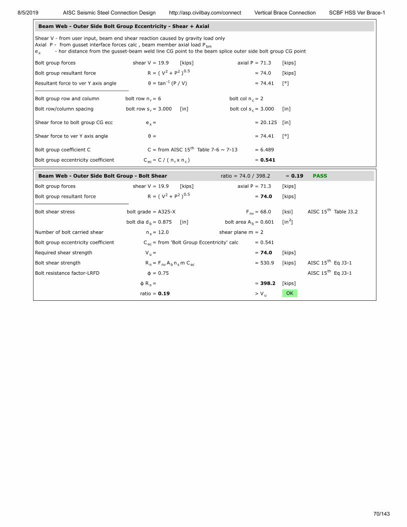
8/5/2019 AISC Seismic Steel Connection Design http://asp.civilbay.com/connect Vertical Brace Connection SCBF HSS Ver Brace-1
70/143
Beam Web - Outer Side Bolt Group Eccentricity - Shear + Axial
Shear V - from user input, beam end shear reaction caused by gravity load onlyAxial P - from gusset interface forces calc , beam member axial load Pe - hor distance from the gusset-beam weld line CG point to the beam splice outer side bolt group CG point
Bolt group forces shear V = 19.9 [kips] axial P = 71.3 [kips]
Bolt group resultant force R = ( V + P ) = 74.0 [kips]
Resultant force to ver Y axis angle θ = tan (P / V) = 74.41 [°]
Bolt group row and column bolt row n = 6 bolt col n = 2
Bolt row/column spacing bolt row s = 3.000 [in] bolt col s = 3.000 [in]
Shear force to bolt group CG ecc e = = 20.125 [in]
Shear force to ver Y axis angle θ = = 74.41 [°]
Bolt group coefficient C C = from AISC 15 Table 7-6 ~ 7-13 = 6.489
Bolt group eccentricity coefficient C = C / ( n x n ) = 0.541
Beam Web - Outer Side Bolt Group - Bolt Shear ratio = 74.0 / 398.2 = 0.19 PASS
Bolt group forces shear V = 19.9 [kips] axial P = 71.3 [kips]
Bolt group resultant force R = ( V + P ) = 74.0 [kips]
Bolt shear stress bolt grade = A325-X F = 68.0 [ksi] AISC 15 Table J3.2
bolt dia d = 0.875 [in] bolt area A = 0.601 [in ]
Number of bolt carried shear n = 12.0 shear plane m = 2
Bolt group eccentricity coefficient C = from 'Bolt Group Eccentricity' calc = 0.541
Required shear strength V = = 74.0 [kips]
Bolt shear strength R = F A n m C = 530.9 [kips] AISC 15 Eq J3-1
Bolt resistance factor-LRFD φ = 0.75 AISC 15 Eq J3-1
φ R = = 398.2 [kips]
ratio = 0.19 > V OK
bm
x
2 2 0.5
-1
r c
r c
x
th
ec r c
2 2 0.5
nvth
b b2
s
ec
u
n nv b s ecth
th
n
u

8/5/2019 AISC Seismic Steel Connection Design http://asp.civilbay.com/connect Vertical Brace Connection SCBF HSS Ver Brace-1
71/143
Beam Web - Outer Side Bolt Group - Bolt Bearing ratio = 74.0 / 388.1 = 0.19 PASS
The bolt group is oriented so that the shear force V is in ver. direction and the axial force P is in hor. direction
Bolt group forces shear V = 19.9 [kips] axial P = 71.3 [kips]
Bolt group resultant force R = ( V + P ) = 74.0 [kips]
Single Bolt Shear Strength
Bolt shear stress bolt grade = A325-X F = 68.0 [ksi] AISC 15 Table J3.2
bolt dia d = 0.875 [in] bolt area A = 0.601 [in ]
Single bolt shear strength R = 2 x F A = 81.8 [kips] AISC 15 Eq J3-1
Bolt Bearing/TearOut Strength on Plate
Bolt hole diameter bolt dia d = ⁄ [in] bolt hole dia d = ⁄ [in] AISC 15 Table J3.3
Bolt spacing & edge distance spacing L = 3.000 [in] edge distance L = 2.000 [in]
Plate tensile strength F = 65.0 [ksi]
Plate thickness t = 0.650 [in]
Interior Bolt
Bolt hole edge clear distance L = L - d = 2.063 [in]
Bolt tear out/bearing strength R = 1.2 L t F ≤ 2.4 d t F AISC 15 Eq J3-6a
= 104.6 ≤ 88.7 = 88.7 [kips]
Bolt strength at interior R = min ( R , R ) = 81.8 [kips]
Edge Bolt
Bolt hole edge clear distance L = L - d / 2 = 1.531 [in]
Bolt tear out/bearing strength R = 1.2 L t F ≤ 2.4 d t F AISC 15 Eq J3-6a
= 77.6 ≤ 88.7 = 77.6 [kips]
Bolt strength at edge R = min ( R , R ) = 77.6 [kips]
Number of bolt interior n = 6 edge n = 6
Bolt group eccentricity coefficient C = from calc in above section = 0.541
Bolt bearing strength for all bolts R = (n R + n R ) C = 517.5 [kips]
Required shear strength V = = 74.0 [kips]
Bolt resistance factor-LRFD φ = 0.75 AISC 15 J3-10
φ R = = 388.1 [kips]
ratio = 0.19 > V OK
Splice Plate - Outer Side Bolt Group Eccentricity - Shear Only
Shear V - from user input, beam end shear reaction caused by gravity load onlye - hor distance from column face to the beam splice outer side bolt group CG point
Bolt group forces shear V = 19.9 [kips] axial P = 0.0 [kips]
Resultant force to ver Y axis angle θ = tan (P / V) = 0.00 [°]
Bolt group row and column bolt row n = 6 bolt col n = 2
Bolt row/column spacing bolt row s = 3.000 [in] bolt col s = 3.000 [in]
Shear force to bolt group CG ecc e = = 34.500 [in]
Shear force to ver Y axis angle θ = = 0.00 [°]
Bolt group coefficient C C = from AISC 15 Table 7-6 ~ 7-13 = 1.552
Bolt group eccentricity coefficient C = C / ( n x n ) = 0.129
2 2 0.5
nvth
b b2
n-bolt nv bth
b7
8 h15
16th
s e
u
c s h
n-t&b-in c u b uth
n-in n-t&b-in n-bolt
c e h
n-t&b-ed c u b uth
n-ed n-t&b-ed n-bolt
in ed
ec
n in n-in ed n-ed ec
u
th
n
u
x
-1
r c
r c
x
th
ec r c

8/5/2019 AISC Seismic Steel Connection Design http://asp.civilbay.com/connect Vertical Brace Connection SCBF HSS Ver Brace-1
72/143
Splice Plate - Outer Side Bolt Group - Bolt Bearing ratio = 10.0 / 47.5 = 0.21 PASS
The bolt group is oriented so that the shear force V is in ver. direction and the axial force P is in hor. direction
Bolt group forces shear V = 10.0 [kips] axial P = 0.0 [kips]
Bolt group resultant force R = ( V + P ) = 10.0 [kips]
Single Bolt Shear Strength
Bolt shear stress bolt grade = A325-X F = 68.0 [ksi] AISC 15 Table J3.2
bolt dia d = 0.875 [in] bolt area A = 0.601 [in ]
Single bolt shear strength R = F A = 40.9 [kips] AISC 15 Eq J3-1
Bolt Bearing/TearOut Strength on Plate
Bolt hole diameter bolt dia d = ⁄ [in] bolt hole dia d = ⁄ [in] AISC 15 Table J3.3
Bolt spacing spacing L = 3.000 [in]
Plate tensile strength F = 65.0 [ksi]
Plate thickness t = 0.375 [in]
Interior Bolt
Bolt hole edge clear distance L = L - d = 2.063 [in]
Bolt tear out/bearing strength R = 1.2 L t F ≤ 2.4 d t m F AISC 15 Eq J3-6a
= 60.3 ≤ 51.2 = 51.2 [kips]
Bolt strength at interior R = min ( R , R ) = 40.9 [kips]
Number of bolt interior n = 12
Bolt group eccentricity coefficient C = from calc in above section = 0.129
Bolt bearing strength for all bolts R = (n R ) C = 63.3 [kips]
Required shear strength V = = 10.0 [kips]
Bolt resistance factor-LRFD φ = 0.75 AISC 15 J3-10
φ R = = 47.5 [kips]
ratio = 0.21 > V OK
2 2 0.5
nvth
b b2
n-bolt nv bth
b7
8 h15
16th
s
u
c s h
n-t&b-in c u b uth
n-in n-t&b-in n-bolt
in
ec
n in n-in ec
u
th
n
u

8/5/2019 AISC Seismic Steel Connection Design http://asp.civilbay.com/connect Vertical Brace Connection SCBF HSS Ver Brace-1
73/143
Splice Plate - Compression Buckling ratio = 35.7 / 256.1 = 0.14 PASS
Plate Compression Check
Plate size width b = 19.000 [in] thickness t = 0.375 [in]
F = 50.0 [ksi] E = 29000 [ksi]
Plate gross area in compression A = b t = 7.125 [in ]
Plate radius of gyration r = t / 12 = 0.108 [in]
Plate effective length factor K = = 1.20 AISC 15 Table C-A-7.1
Plate unbraced length L = = 5.000 [in]
Plate slenderness KL/r = 1.20 x L / r = 55.43
when KL
r > 25 , use Chapter E AISC 15 J4.4 (b)
Elastic buckling stress F = π E
( KL/r ) = 93.17 [ksi] AISC 15 Eq E3-4
when KL
r ≤ 4.71 (
E
F ) = 113.43 AISC 15 E3 (a)
Critical stress F = 0.658 F = 39.94 [ksi] AISC 15 Eq E3-2
Plate compression required P = 0.5 x beam axial compression P = 35.7 [kips]
Plate compression provided R = F x A = 284.6 [kips] AISC 15 Eq E3-1
Resistance factor-LRFD φ = 0.90 AISC 15 E1
φ R = = 256.1 [kips]
ratio = 0.14 > P OK
Splice Plate - Shear Yielding ratio = 19.9 / 427.5 = 0.05 PASS
Splice Plate Shear Yielding
Plate size width b = 19.000 [in] thickness t = 0.375 [in]
Plate yield strength F = 50.0 [ksi]
Plate gross area in shear A = b t x 2 side = 14.250 [in ]
Shear force required V = = 19.9 [kips]
Plate shear yielding strength R = 0.6 F A = 427.5 [kips] AISC 15 Eq J4-3
Resistance factor-LRFD φ = 1.00 AISC 15 Eq J4-3
φ R = = 427.5 [kips]
ratio = 0.05 > V OK
Splice Plate - Flexural Yielding ratio = 54.73 / 253.83 = 0.22 PASS
Plate width & thick width b = 19.000 [in] thick t = 0.375 [in]
yield F = 50.0 [ksi]
Beam end shear reaction caused bygravity load only
V = from user input = 19.9 [kips]
Ecc from column face to outer boltgroup first bolt line
e = = 33.000 [in]
Flexural strength required M = V x e = 54.73 [kip-ft]
Shear plate - plastic modulus Z = ( b x t ) / 4 x 2 side = 67.69 [in ]
Flexural strength available M = φ F Z φ=0.90 = 253.83 [kip-ft]
ratio = 0.22 > M OK
p p
y
g p p2
p √th
u
u
th
e
2
2th
y
0.5 th
cr( F / F )y e y
th
u
n cr gth
th
n
u
p p
y
gv p p2
u
n y gvth
th
n
u
p p
y
r
p p2p
3
c y p
r
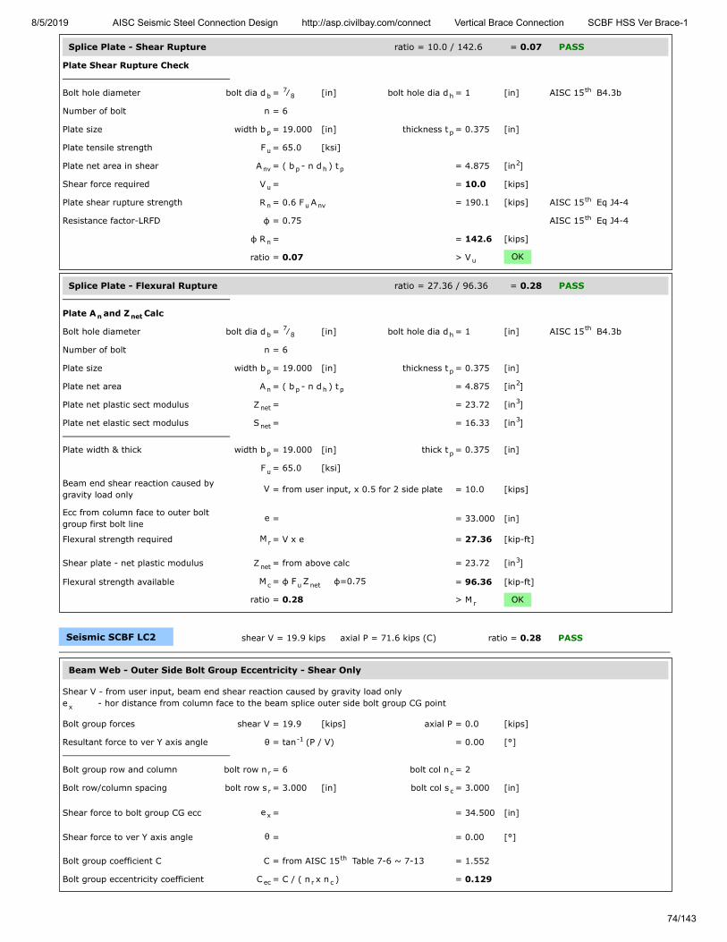
8/5/2019 AISC Seismic Steel Connection Design http://asp.civilbay.com/connect Vertical Brace Connection SCBF HSS Ver Brace-1
74/143
Splice Plate - Shear Rupture ratio = 10.0 / 142.6 = 0.07 PASS
Plate Shear Rupture Check
Bolt hole diameter bolt dia d = ⁄ [in] bolt hole dia d = 1 [in] AISC 15 B4.3b
Number of bolt n = 6
Plate size width b = 19.000 [in] thickness t = 0.375 [in]
Plate tensile strength F = 65.0 [ksi]
Plate net area in shear A = ( b - n d ) t = 4.875 [in ]
Shear force required V = = 10.0 [kips]
Plate shear rupture strength R = 0.6 F A = 190.1 [kips] AISC 15 Eq J4-4
Resistance factor-LRFD φ = 0.75 AISC 15 Eq J4-4
φ R = = 142.6 [kips]
ratio = 0.07 > V OK
Splice Plate - Flexural Rupture ratio = 27.36 / 96.36 = 0.28 PASS
Plate A and Z Calc
Bolt hole diameter bolt dia d = ⁄ [in] bolt hole dia d = 1 [in] AISC 15 B4.3b
Number of bolt n = 6
Plate size width b = 19.000 [in] thickness t = 0.375 [in]
Plate net area A = ( b - n d ) t = 4.875 [in ]
Plate net plastic sect modulus Z = = 23.72 [in ]
Plate net elastic sect modulus S = = 16.33 [in ]
Plate width & thick width b = 19.000 [in] thick t = 0.375 [in]
F = 65.0 [ksi]
Beam end shear reaction caused bygravity load only
V = from user input, x 0.5 for 2 side plate = 10.0 [kips]
Ecc from column face to outer boltgroup first bolt line
e = = 33.000 [in]
Flexural strength required M = V x e = 27.36 [kip-ft]
Shear plate - net plastic modulus Z = from above calc = 23.72 [in ]
Flexural strength available M = φ F Z φ=0.75 = 96.36 [kip-ft]
ratio = 0.28 > M OK
Seismic SCBF LC2 shear V = 19.9 kips axial P = 71.6 kips (C) ratio = 0.28 PASS
Beam Web - Outer Side Bolt Group Eccentricity - Shear Only
Shear V - from user input, beam end shear reaction caused by gravity load onlye - hor distance from column face to the beam splice outer side bolt group CG point
Bolt group forces shear V = 19.9 [kips] axial P = 0.0 [kips]
Resultant force to ver Y axis angle θ = tan (P / V) = 0.00 [°]
Bolt group row and column bolt row n = 6 bolt col n = 2
Bolt row/column spacing bolt row s = 3.000 [in] bolt col s = 3.000 [in]
Shear force to bolt group CG ecc e = = 34.500 [in]
Shear force to ver Y axis angle θ = = 0.00 [°]
Bolt group coefficient C C = from AISC 15 Table 7-6 ~ 7-13 = 1.552
Bolt group eccentricity coefficient C = C / ( n x n ) = 0.129
b7
8 hth
p p
u
nv p h p2
u
n u nvth
th
n
u
n net
b7
8 hth
p p
n p h p2
net3
net3
p p
u
r
net3
c u net
r
x
-1
r c
r c
x
th
ec r c

8/5/2019 AISC Seismic Steel Connection Design http://asp.civilbay.com/connect Vertical Brace Connection SCBF HSS Ver Brace-1
75/143
Beam Web - Outer Side Bolt Group - Bolt Shear ratio = 19.9 / 94.9 = 0.21 PASS
Bolt group forces shear V = 19.9 [kips] axial P = 0.0 [kips]
Bolt group resultant force R = ( V + P ) = 19.9 [kips]
Bolt shear stress bolt grade = A325-X F = 68.0 [ksi] AISC 15 Table J3.2
bolt dia d = 0.875 [in] bolt area A = 0.601 [in ]
Number of bolt carried shear n = 12.0 shear plane m = 2
Bolt group eccentricity coefficient C = from 'Bolt Group Eccentricity' calc = 0.129
Required shear strength V = = 19.9 [kips]
Bolt shear strength R = F A n m C = 126.6 [kips] AISC 15 Eq J3-1
Bolt resistance factor-LRFD φ = 0.75 AISC 15 Eq J3-1
φ R = = 94.9 [kips]
ratio = 0.21 > V OK
Beam Web - Outer Side Bolt Group - Bolt Bearing ratio = 19.9 / 94.9 = 0.21 PASS
The bolt group is oriented so that the shear force V is in ver. direction and the axial force P is in hor. direction
Bolt group forces shear V = 19.9 [kips] axial P = 0.0 [kips]
Bolt group resultant force R = ( V + P ) = 19.9 [kips]
Single Bolt Shear Strength
Bolt shear stress bolt grade = A325-X F = 68.0 [ksi] AISC 15 Table J3.2
bolt dia d = 0.875 [in] bolt area A = 0.601 [in ]
Single bolt shear strength R = 2 x F A = 81.8 [kips] AISC 15 Eq J3-1
Bolt Bearing/TearOut Strength on Plate
Bolt hole diameter bolt dia d = ⁄ [in] bolt hole dia d = ⁄ [in] AISC 15 Table J3.3
Bolt spacing spacing L = 3.000 [in]
Plate tensile strength F = 65.0 [ksi]
Plate thickness t = 0.650 [in]
Interior Bolt
Bolt hole edge clear distance L = L - d = 2.063 [in]
Bolt tear out/bearing strength R = 1.2 L t F ≤ 2.4 d t m F AISC 15 Eq J3-6a
= 104.6 ≤ 88.7 = 88.7 [kips]
Bolt strength at interior R = min ( R , R ) = 81.8 [kips]
Number of bolt interior n = 12
Bolt group eccentricity coefficient C = from calc in above section = 0.129
Bolt bearing strength for all bolts R = (n R ) C = 126.6 [kips]
Required shear strength V = = 19.9 [kips]
Bolt resistance factor-LRFD φ = 0.75 AISC 15 J3-10
φ R = = 94.9 [kips]
ratio = 0.21 > V OK
2 2 0.5
nvth
b b2
s
ec
u
n nv b s ecth
th
n
u
2 2 0.5
nvth
b b2
n-bolt nv bth
b7
8 h15
16th
s
u
c s h
n-t&b-in c u b uth
n-in n-t&b-in n-bolt
in
ec
n in n-in ec
u
th
n
u

8/5/2019 AISC Seismic Steel Connection Design http://asp.civilbay.com/connect Vertical Brace Connection SCBF HSS Ver Brace-1
76/143
Beam Web - Inner Side Bolt Group Eccentricity - Shear Only
Shear V - from user input, beam end shear reaction caused by gravity load onlye - hor distance from column face to the beam splice inner side bolt group CG point
Bolt group forces shear V = 19.9 [kips] axial P = 0.0 [kips]
Resultant force to ver Y axis angle θ = tan (P / V) = 0.00 [°]
Bolt group row and column bolt row n = 6 bolt col n = 2
Bolt row/column spacing bolt row s = 3.000 [in] bolt col s = 3.000 [in]
Shear force to bolt group CG ecc e = = 26.500 [in]
Shear force to ver Y axis angle θ = = 0.00 [°]
Bolt group coefficient C C = from AISC 15 Table 7-6 ~ 7-13 = 2.007
Bolt group eccentricity coefficient C = C / ( n x n ) = 0.167
Beam Web - Inner Side Bolt Group - Bolt Shear ratio = 19.9 / 122.9 = 0.16 PASS
Bolt group forces shear V = 19.9 [kips] axial P = 0.0 [kips]
Bolt group resultant force R = ( V + P ) = 19.9 [kips]
Bolt shear stress bolt grade = A325-X F = 68.0 [ksi] AISC 15 Table J3.2
bolt dia d = 0.875 [in] bolt area A = 0.601 [in ]
Number of bolt carried shear n = 12.0 shear plane m = 2
Bolt group eccentricity coefficient C = from 'Bolt Group Eccentricity' calc = 0.167
Required shear strength V = = 19.9 [kips]
Bolt shear strength R = F A n m C = 163.9 [kips] AISC 15 Eq J3-1
Bolt resistance factor-LRFD φ = 0.75 AISC 15 Eq J3-1
φ R = = 122.9 [kips]
ratio = 0.16 > V OK
x
-1
r c
r c
x
th
ec r c
2 2 0.5
nvth
b b2
s
ec
u
n nv b s ecth
th
n
u

8/5/2019 AISC Seismic Steel Connection Design http://asp.civilbay.com/connect Vertical Brace Connection SCBF HSS Ver Brace-1
77/143
Beam Web - Inner Side Bolt Group - Bolt Bearing ratio = 19.9 / 122.9 = 0.16 PASS
The bolt group is oriented so that the shear force V is in ver. direction and the axial force P is in hor. direction
Bolt group forces shear V = 19.9 [kips] axial P = 0.0 [kips]
Bolt group resultant force R = ( V + P ) = 19.9 [kips]
Single Bolt Shear Strength
Bolt shear stress bolt grade = A325-X F = 68.0 [ksi] AISC 15 Table J3.2
bolt dia d = 0.875 [in] bolt area A = 0.601 [in ]
Single bolt shear strength R = 2 x F A = 81.8 [kips] AISC 15 Eq J3-1
Bolt Bearing/TearOut Strength on Plate
Bolt hole diameter bolt dia d = ⁄ [in] bolt hole dia d = ⁄ [in] AISC 15 Table J3.3
Bolt spacing spacing L = 3.000 [in]
Plate tensile strength F = 65.0 [ksi]
Plate thickness t = 0.650 [in]
Interior Bolt
Bolt hole edge clear distance L = L - d = 2.063 [in]
Bolt tear out/bearing strength R = 1.2 L t F ≤ 2.4 d t m F AISC 15 Eq J3-6a
= 104.6 ≤ 88.7 = 88.7 [kips]
Bolt strength at interior R = min ( R , R ) = 81.8 [kips]
Number of bolt interior n = 12
Bolt group eccentricity coefficient C = from calc in above section = 0.167
Bolt bearing strength for all bolts R = (n R ) C = 163.9 [kips]
Required shear strength V = = 19.9 [kips]
Bolt resistance factor-LRFD φ = 0.75 AISC 15 J3-10
φ R = = 122.9 [kips]
ratio = 0.16 > V OK
Beam Web - Inner Side Bolt Group Eccentricity - Shear + Axial
Shear V - from user input, beam end shear reaction caused by gravity load onlyAxial P - from gusset interface forces calc , beam member axial load Pe - hor distance from the gusset-beam weld line CG point to the beam splice inner side bolt group CG point
Bolt group forces shear V = 19.9 [kips] axial P = 71.6 [kips]
Bolt group resultant force R = ( V + P ) = 74.3 [kips]
Resultant force to ver Y axis angle θ = tan (P / V) = 74.47 [°]
Bolt group row and column bolt row n = 6 bolt col n = 2
Bolt row/column spacing bolt row s = 3.000 [in] bolt col s = 3.000 [in]
Shear force to bolt group CG ecc e = = 12.125 [in]
Shear force to ver Y axis angle θ = = 74.47 [°]
Bolt group coefficient C C = from AISC 15 Table 7-6 ~ 7-13 = 8.077
Bolt group eccentricity coefficient C = C / ( n x n ) = 0.673
2 2 0.5
nvth
b b2
n-bolt nv bth
b7
8 h15
16th
s
u
c s h
n-t&b-in c u b uth
n-in n-t&b-in n-bolt
in
ec
n in n-in ec
u
th
n
u
bm
x
2 2 0.5
-1
r c
r c
x
th
ec r c
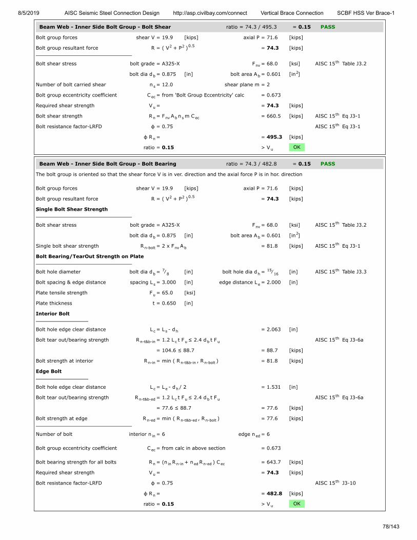
8/5/2019 AISC Seismic Steel Connection Design http://asp.civilbay.com/connect Vertical Brace Connection SCBF HSS Ver Brace-1
78/143
Beam Web - Inner Side Bolt Group - Bolt Shear ratio = 74.3 / 495.3 = 0.15 PASS
Bolt group forces shear V = 19.9 [kips] axial P = 71.6 [kips]
Bolt group resultant force R = ( V + P ) = 74.3 [kips]
Bolt shear stress bolt grade = A325-X F = 68.0 [ksi] AISC 15 Table J3.2
bolt dia d = 0.875 [in] bolt area A = 0.601 [in ]
Number of bolt carried shear n = 12.0 shear plane m = 2
Bolt group eccentricity coefficient C = from 'Bolt Group Eccentricity' calc = 0.673
Required shear strength V = = 74.3 [kips]
Bolt shear strength R = F A n m C = 660.5 [kips] AISC 15 Eq J3-1
Bolt resistance factor-LRFD φ = 0.75 AISC 15 Eq J3-1
φ R = = 495.3 [kips]
ratio = 0.15 > V OK
Beam Web - Inner Side Bolt Group - Bolt Bearing ratio = 74.3 / 482.8 = 0.15 PASS
The bolt group is oriented so that the shear force V is in ver. direction and the axial force P is in hor. direction
Bolt group forces shear V = 19.9 [kips] axial P = 71.6 [kips]
Bolt group resultant force R = ( V + P ) = 74.3 [kips]
Single Bolt Shear Strength
Bolt shear stress bolt grade = A325-X F = 68.0 [ksi] AISC 15 Table J3.2
bolt dia d = 0.875 [in] bolt area A = 0.601 [in ]
Single bolt shear strength R = 2 x F A = 81.8 [kips] AISC 15 Eq J3-1
Bolt Bearing/TearOut Strength on Plate
Bolt hole diameter bolt dia d = ⁄ [in] bolt hole dia d = ⁄ [in] AISC 15 Table J3.3
Bolt spacing & edge distance spacing L = 3.000 [in] edge distance L = 2.000 [in]
Plate tensile strength F = 65.0 [ksi]
Plate thickness t = 0.650 [in]
Interior Bolt
Bolt hole edge clear distance L = L - d = 2.063 [in]
Bolt tear out/bearing strength R = 1.2 L t F ≤ 2.4 d t F AISC 15 Eq J3-6a
= 104.6 ≤ 88.7 = 88.7 [kips]
Bolt strength at interior R = min ( R , R ) = 81.8 [kips]
Edge Bolt
Bolt hole edge clear distance L = L - d / 2 = 1.531 [in]
Bolt tear out/bearing strength R = 1.2 L t F ≤ 2.4 d t F AISC 15 Eq J3-6a
= 77.6 ≤ 88.7 = 77.6 [kips]
Bolt strength at edge R = min ( R , R ) = 77.6 [kips]
Number of bolt interior n = 6 edge n = 6
Bolt group eccentricity coefficient C = from calc in above section = 0.673
Bolt bearing strength for all bolts R = (n R + n R ) C = 643.7 [kips]
Required shear strength V = = 74.3 [kips]
Bolt resistance factor-LRFD φ = 0.75 AISC 15 J3-10
φ R = = 482.8 [kips]
ratio = 0.15 > V OK
2 2 0.5
nvth
b b2
s
ec
u
n nv b s ecth
th
n
u
2 2 0.5
nvth
b b2
n-bolt nv bth
b7
8 h15
16th
s e
u
c s h
n-t&b-in c u b uth
n-in n-t&b-in n-bolt
c e h
n-t&b-ed c u b uth
n-ed n-t&b-ed n-bolt
in ed
ec
n in n-in ed n-ed ec
u
th
n
u

8/5/2019 AISC Seismic Steel Connection Design http://asp.civilbay.com/connect Vertical Brace Connection SCBF HSS Ver Brace-1
79/143
Beam Web - Outer Side Bolt Group Eccentricity - Shear + Axial
Shear V - from user input, beam end shear reaction caused by gravity load onlyAxial P - from gusset interface forces calc , beam member axial load Pe - hor distance from the gusset-beam weld line CG point to the beam splice outer side bolt group CG point
Bolt group forces shear V = 19.9 [kips] axial P = 71.6 [kips]
Bolt group resultant force R = ( V + P ) = 74.3 [kips]
Resultant force to ver Y axis angle θ = tan (P / V) = 74.47 [°]
Bolt group row and column bolt row n = 6 bolt col n = 2
Bolt row/column spacing bolt row s = 3.000 [in] bolt col s = 3.000 [in]
Shear force to bolt group CG ecc e = = 20.125 [in]
Shear force to ver Y axis angle θ = = 74.47 [°]
Bolt group coefficient C C = from AISC 15 Table 7-6 ~ 7-13 = 6.501
Bolt group eccentricity coefficient C = C / ( n x n ) = 0.542
Beam Web - Outer Side Bolt Group - Bolt Shear ratio = 74.3 / 398.9 = 0.19 PASS
Bolt group forces shear V = 19.9 [kips] axial P = 71.6 [kips]
Bolt group resultant force R = ( V + P ) = 74.3 [kips]
Bolt shear stress bolt grade = A325-X F = 68.0 [ksi] AISC 15 Table J3.2
bolt dia d = 0.875 [in] bolt area A = 0.601 [in ]
Number of bolt carried shear n = 12.0 shear plane m = 2
Bolt group eccentricity coefficient C = from 'Bolt Group Eccentricity' calc = 0.542
Required shear strength V = = 74.3 [kips]
Bolt shear strength R = F A n m C = 531.9 [kips] AISC 15 Eq J3-1
Bolt resistance factor-LRFD φ = 0.75 AISC 15 Eq J3-1
φ R = = 398.9 [kips]
ratio = 0.19 > V OK
bm
x
2 2 0.5
-1
r c
r c
x
th
ec r c
2 2 0.5
nvth
b b2
s
ec
u
n nv b s ecth
th
n
u

8/5/2019 AISC Seismic Steel Connection Design http://asp.civilbay.com/connect Vertical Brace Connection SCBF HSS Ver Brace-1
80/143
Beam Web - Outer Side Bolt Group - Bolt Bearing ratio = 74.3 / 388.8 = 0.19 PASS
The bolt group is oriented so that the shear force V is in ver. direction and the axial force P is in hor. direction
Bolt group forces shear V = 19.9 [kips] axial P = 71.6 [kips]
Bolt group resultant force R = ( V + P ) = 74.3 [kips]
Single Bolt Shear Strength
Bolt shear stress bolt grade = A325-X F = 68.0 [ksi] AISC 15 Table J3.2
bolt dia d = 0.875 [in] bolt area A = 0.601 [in ]
Single bolt shear strength R = 2 x F A = 81.8 [kips] AISC 15 Eq J3-1
Bolt Bearing/TearOut Strength on Plate
Bolt hole diameter bolt dia d = ⁄ [in] bolt hole dia d = ⁄ [in] AISC 15 Table J3.3
Bolt spacing & edge distance spacing L = 3.000 [in] edge distance L = 2.000 [in]
Plate tensile strength F = 65.0 [ksi]
Plate thickness t = 0.650 [in]
Interior Bolt
Bolt hole edge clear distance L = L - d = 2.063 [in]
Bolt tear out/bearing strength R = 1.2 L t F ≤ 2.4 d t F AISC 15 Eq J3-6a
= 104.6 ≤ 88.7 = 88.7 [kips]
Bolt strength at interior R = min ( R , R ) = 81.8 [kips]
Edge Bolt
Bolt hole edge clear distance L = L - d / 2 = 1.531 [in]
Bolt tear out/bearing strength R = 1.2 L t F ≤ 2.4 d t F AISC 15 Eq J3-6a
= 77.6 ≤ 88.7 = 77.6 [kips]
Bolt strength at edge R = min ( R , R ) = 77.6 [kips]
Number of bolt interior n = 6 edge n = 6
Bolt group eccentricity coefficient C = from calc in above section = 0.542
Bolt bearing strength for all bolts R = (n R + n R ) C = 518.4 [kips]
Required shear strength V = = 74.3 [kips]
Bolt resistance factor-LRFD φ = 0.75 AISC 15 J3-10
φ R = = 388.8 [kips]
ratio = 0.19 > V OK
Splice Plate - Outer Side Bolt Group Eccentricity - Shear Only
Shear V - from user input, beam end shear reaction caused by gravity load onlye - hor distance from column face to the beam splice outer side bolt group CG point
Bolt group forces shear V = 19.9 [kips] axial P = 0.0 [kips]
Resultant force to ver Y axis angle θ = tan (P / V) = 0.00 [°]
Bolt group row and column bolt row n = 6 bolt col n = 2
Bolt row/column spacing bolt row s = 3.000 [in] bolt col s = 3.000 [in]
Shear force to bolt group CG ecc e = = 34.500 [in]
Shear force to ver Y axis angle θ = = 0.00 [°]
Bolt group coefficient C C = from AISC 15 Table 7-6 ~ 7-13 = 1.552
Bolt group eccentricity coefficient C = C / ( n x n ) = 0.129
2 2 0.5
nvth
b b2
n-bolt nv bth
b7
8 h15
16th
s e
u
c s h
n-t&b-in c u b uth
n-in n-t&b-in n-bolt
c e h
n-t&b-ed c u b uth
n-ed n-t&b-ed n-bolt
in ed
ec
n in n-in ed n-ed ec
u
th
n
u
x
-1
r c
r c
x
th
ec r c

8/5/2019 AISC Seismic Steel Connection Design http://asp.civilbay.com/connect Vertical Brace Connection SCBF HSS Ver Brace-1
81/143
Splice Plate - Outer Side Bolt Group - Bolt Bearing ratio = 10.0 / 47.5 = 0.21 PASS
The bolt group is oriented so that the shear force V is in ver. direction and the axial force P is in hor. direction
Bolt group forces shear V = 10.0 [kips] axial P = 0.0 [kips]
Bolt group resultant force R = ( V + P ) = 10.0 [kips]
Single Bolt Shear Strength
Bolt shear stress bolt grade = A325-X F = 68.0 [ksi] AISC 15 Table J3.2
bolt dia d = 0.875 [in] bolt area A = 0.601 [in ]
Single bolt shear strength R = F A = 40.9 [kips] AISC 15 Eq J3-1
Bolt Bearing/TearOut Strength on Plate
Bolt hole diameter bolt dia d = ⁄ [in] bolt hole dia d = ⁄ [in] AISC 15 Table J3.3
Bolt spacing spacing L = 3.000 [in]
Plate tensile strength F = 65.0 [ksi]
Plate thickness t = 0.375 [in]
Interior Bolt
Bolt hole edge clear distance L = L - d = 2.063 [in]
Bolt tear out/bearing strength R = 1.2 L t F ≤ 2.4 d t m F AISC 15 Eq J3-6a
= 60.3 ≤ 51.2 = 51.2 [kips]
Bolt strength at interior R = min ( R , R ) = 40.9 [kips]
Number of bolt interior n = 12
Bolt group eccentricity coefficient C = from calc in above section = 0.129
Bolt bearing strength for all bolts R = (n R ) C = 63.3 [kips]
Required shear strength V = = 10.0 [kips]
Bolt resistance factor-LRFD φ = 0.75 AISC 15 J3-10
φ R = = 47.5 [kips]
ratio = 0.21 > V OK
2 2 0.5
nvth
b b2
n-bolt nv bth
b7
8 h15
16th
s
u
c s h
n-t&b-in c u b uth
n-in n-t&b-in n-bolt
in
ec
n in n-in ec
u
th
n
u
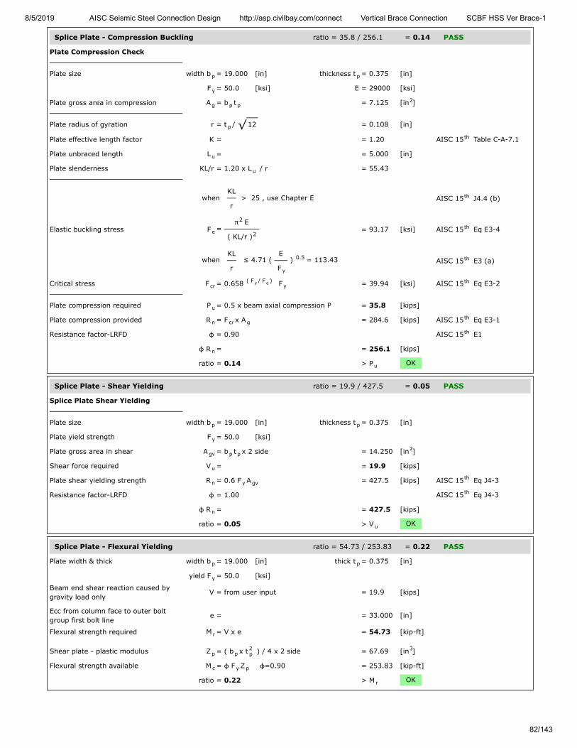
8/5/2019 AISC Seismic Steel Connection Design http://asp.civilbay.com/connect Vertical Brace Connection SCBF HSS Ver Brace-1
82/143
Splice Plate - Compression Buckling ratio = 35.8 / 256.1 = 0.14 PASS
Plate Compression Check
Plate size width b = 19.000 [in] thickness t = 0.375 [in]
F = 50.0 [ksi] E = 29000 [ksi]
Plate gross area in compression A = b t = 7.125 [in ]
Plate radius of gyration r = t / 12 = 0.108 [in]
Plate effective length factor K = = 1.20 AISC 15 Table C-A-7.1
Plate unbraced length L = = 5.000 [in]
Plate slenderness KL/r = 1.20 x L / r = 55.43
when KL
r > 25 , use Chapter E AISC 15 J4.4 (b)
Elastic buckling stress F = π E
( KL/r ) = 93.17 [ksi] AISC 15 Eq E3-4
when KL
r ≤ 4.71 (
E
F ) = 113.43 AISC 15 E3 (a)
Critical stress F = 0.658 F = 39.94 [ksi] AISC 15 Eq E3-2
Plate compression required P = 0.5 x beam axial compression P = 35.8 [kips]
Plate compression provided R = F x A = 284.6 [kips] AISC 15 Eq E3-1
Resistance factor-LRFD φ = 0.90 AISC 15 E1
φ R = = 256.1 [kips]
ratio = 0.14 > P OK
Splice Plate - Shear Yielding ratio = 19.9 / 427.5 = 0.05 PASS
Splice Plate Shear Yielding
Plate size width b = 19.000 [in] thickness t = 0.375 [in]
Plate yield strength F = 50.0 [ksi]
Plate gross area in shear A = b t x 2 side = 14.250 [in ]
Shear force required V = = 19.9 [kips]
Plate shear yielding strength R = 0.6 F A = 427.5 [kips] AISC 15 Eq J4-3
Resistance factor-LRFD φ = 1.00 AISC 15 Eq J4-3
φ R = = 427.5 [kips]
ratio = 0.05 > V OK
Splice Plate - Flexural Yielding ratio = 54.73 / 253.83 = 0.22 PASS
Plate width & thick width b = 19.000 [in] thick t = 0.375 [in]
yield F = 50.0 [ksi]
Beam end shear reaction caused bygravity load only
V = from user input = 19.9 [kips]
Ecc from column face to outer boltgroup first bolt line
e = = 33.000 [in]
Flexural strength required M = V x e = 54.73 [kip-ft]
Shear plate - plastic modulus Z = ( b x t ) / 4 x 2 side = 67.69 [in ]
Flexural strength available M = φ F Z φ=0.90 = 253.83 [kip-ft]
ratio = 0.22 > M OK
p p
y
g p p2
p √th
u
u
th
e
2
2th
y
0.5 th
cr( F / F )y e y
th
u
n cr gth
th
n
u
p p
y
gv p p2
u
n y gvth
th
n
u
p p
y
r
p p2p
3
c y p
r

8/5/2019 AISC Seismic Steel Connection Design http://asp.civilbay.com/connect Vertical Brace Connection SCBF HSS Ver Brace-1
83/143
Splice Plate - Shear Rupture ratio = 10.0 / 142.6 = 0.07 PASS
Plate Shear Rupture Check
Bolt hole diameter bolt dia d = ⁄ [in] bolt hole dia d = 1 [in] AISC 15 B4.3b
Number of bolt n = 6
Plate size width b = 19.000 [in] thickness t = 0.375 [in]
Plate tensile strength F = 65.0 [ksi]
Plate net area in shear A = ( b - n d ) t = 4.875 [in ]
Shear force required V = = 10.0 [kips]
Plate shear rupture strength R = 0.6 F A = 190.1 [kips] AISC 15 Eq J4-4
Resistance factor-LRFD φ = 0.75 AISC 15 Eq J4-4
φ R = = 142.6 [kips]
ratio = 0.07 > V OK
Splice Plate - Flexural Rupture ratio = 27.36 / 96.36 = 0.28 PASS
Plate A and Z Calc
Bolt hole diameter bolt dia d = ⁄ [in] bolt hole dia d = 1 [in] AISC 15 B4.3b
Number of bolt n = 6
Plate size width b = 19.000 [in] thickness t = 0.375 [in]
Plate net area A = ( b - n d ) t = 4.875 [in ]
Plate net plastic sect modulus Z = = 23.72 [in ]
Plate net elastic sect modulus S = = 16.33 [in ]
Plate width & thick width b = 19.000 [in] thick t = 0.375 [in]
F = 65.0 [ksi]
Beam end shear reaction caused bygravity load only
V = from user input, x 0.5 for 2 side plate = 10.0 [kips]
Ecc from column face to outer boltgroup first bolt line
e = = 33.000 [in]
Flexural strength required M = V x e = 27.36 [kip-ft]
Shear plate - net plastic modulus Z = from above calc = 23.72 [in ]
Flexural strength available M = φ F Z φ=0.75 = 96.36 [kip-ft]
ratio = 0.28 > M OK
Seismic - SCBF LC3 & LC4 Gusset Interface Forces Calc
b7
8 hth
p p
u
nv p h p2
u
n u nvth
th
n
u
n net
b7
8 hth
p p
n p h p2
net3
net3
p p
u
r
net3
c u net
r

8/5/2019 AISC Seismic Steel Connection Design http://asp.civilbay.com/connect Vertical Brace Connection SCBF HSS Ver Brace-1
84/143
Brace - SCBF Load Case LC3
Top and bottom brace force Top P = -559.7 [kips] (T) Bot P = 157.3 [kips] (C)
Beam end shear & transfer force Shear R = 19.9 [kips] Transfer A = -27.6 [kips]
Top Brace Interface Forces
Refer to AISC 15 Page 13-4 and Fig. 13-2 for all charts and definitions of variables and symbols shown in calculation below
e = 12.350 [in] e = 6.450 [in]
α = 14.000 [in] β = 9.625 [in]
θ = 45.0 [°]
K = e tanθ - e = 5.900 [in] AISC 15 Eq. 13-16
D = tan θ + (α
β) = 3.116 AISC 15 Eq. 13-24
K' = α ( tan θ + α
β) = 34.364 AISC 15 Eq. 13-23
α = [ K' tan θ + K (α
β) ] / D = 14.000 [in] AISC 15 Eq. 13-21
β = ( K' - K tan θ ) / D = 8.100 [in] AISC 15 Eq. 13-22
r = [ ( e + β ) + ( e + α ) ] = 28.921 [in] AISC 15 Eq. 13-6
Brace axial force P = from seismic brace force calc = -559.7 [kips] in tension
Gusset to Column Interface Forces
Shear force V = ( β / r ) P = -156.8 [kips] AISC 15 Eq. 13-2
Axial force H = ( e / r ) P = -124.8 [kips] AISC 15 Eq. 13-3
Moment M = H ( β - β ) = 15.86 [kip-ft] AISC 15 Eq. 13-19
Gusset to Beam Interface Forces
Shear force H = ( α / r ) P = -270.9 [kips] AISC 15 Eq. 13-5
Axial force V = ( e / r ) P = -239.0 [kips] AISC 15 Eq. 13-4
Moment M = V ( α - α ) = 0.00 [kip-ft] AISC 15 Eq. 13-17
Bottom Brace Interface Forces
Refer to AISC 15 Page 13-4 and Fig. 13-2 for all charts and definitions of variables and symbols shown in calculation below
e = 12.350 [in] e = 6.450 [in]
α = 14.750 [in] β = 10.375 [in]
θ = 45.0 [°]
K = e tanθ - e = 5.900 [in] AISC 15 Eq. 13-16
D = tan θ + (α
β) = 3.021 AISC 15 Eq. 13-24
K' = α ( tan θ + α
β) = 35.720 AISC 15 Eq. 13-23
α = [ K' tan θ + K (α
β) ] / D = 14.750 [in] AISC 15 Eq. 13-21
top bot
b b
th
b c
b cth
2 2 th
th
2 th
th
b2
c2 0.5 th
u
c uth
c c uth
c cth
b uth
b b uth
b bth
th
b c
b cth
2 2 th
th
2 th
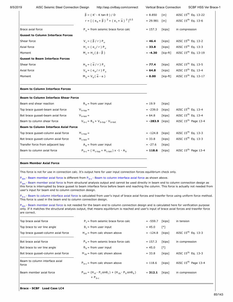
8/5/2019 AISC Seismic Steel Connection Design http://asp.civilbay.com/connect Vertical Brace Connection SCBF HSS Ver Brace-1
85/143
β = ( K' - K tan θ ) / D = 8.850 [in] AISC 15 Eq. 13-22
r = [ ( e + β ) + ( e + α ) ] = 29.981 [in] AISC 15 Eq. 13-6
Brace axial force P = from seismic brace force calc = 157.3 [kips] in compression
Gusset to Column Interface Forces
Shear force V = ( β / r ) P = 46.4 [kips] AISC 15 Eq. 13-2
Axial force H = ( e / r ) P = 33.8 [kips] AISC 15 Eq. 13-3
Moment M = H ( β - β ) = -4.30 [kip-ft] AISC 15 Eq. 13-19
Gusset to Beam Interface Forces
Shear force H = ( α / r ) P = 77.4 [kips] AISC 15 Eq. 13-5
Axial force V = ( e / r ) P = 64.8 [kips] AISC 15 Eq. 13-4
Moment M = V ( α - α ) = 0.00 [kip-ft] AISC 15 Eq. 13-17
Beam to Column Interface Forces
Beam to Column Interface Shear Force
Beam end shear reaction R = from user input = 19.9 [kips]
Top brace gusset-beam axial force V = = -239.0 [kips] AISC 15 Eq. 13-4
Bot brace gusset-beam axial force V = = 64.8 [kips] AISC 15 Eq. 13-4
Beam to column shear force V = R + V - V = -283.9 [kips] AISC 15 Page 13-4
Beam to Column Interface Axial Force
Top brace gusset-column axial force H = = -124.8 [kips] AISC 15 Eq. 13-3
Bot brace gusset-column axial force H = = 33.8 [kips] AISC 15 Eq. 13-3
Transfer force from adjacent bay A = from user input = -27.6 [kips]
Beam to column axial force P = ( H + H ) x -1 - A = 118.6 [kips] AISC 15 Page 13-4
Beam Member Axial Force
This force is not for use in connection calc. It's output here for user input connection forces equilibrium check only.
P - Beam member axial force is different from P - Beam to column interface axial force as shown above.
P - Beam member axial force is from structural analysis output and cannot be used directly in beam end to column connection design asthis force is interrupted by brace gusset to beam interface force before beam end reaching the column. This force is actually not needed fromuser's input for beam end to column connection design.
P - Beam to column interface axial force is calculated from user's input of brace axial forces and trasnfer force using uniform force method.This force is used in the beam end to column connection design.
P - Beam member axial force is not needed for the beam end to column connection design and is calculated here for verification purposeonly. If it matches the structural analysis output, that means equilibrium is reached and user's input of brace axial forces and trasnfer forceare correct.
Top brace axial force P = from seismic brace force calc = -559.7 [kips] in tension
Top brace to ver line angle θ = from user input = 45.0 [°]
Top brace gusset-column axial force H = from calc shown above = -124.8 [kips] AISC 15 Eq. 13-3
Bot brace axial force P = from seismic brace force calc = 157.3 [kips] in compression
Bot brace to ver line angle θ = from user input = 45.0 [°]
Bot brace gusset-column axial force H = from calc shown above = 33.8 [kips] AISC 15 Eq. 13-3
Beam to column interface axialforce
P = from calc shown above = 118.6 [kips] AISC 15 Page 13-4
Beam member axial force P = (H - P sinθ ) + (H - P sinθ ) = 312.1 [kips] in compression
+ P
Brace - SCBF Load Case LC4
th
b2
c2 0.5 th
u
c uth
c c uth
c cth
b uth
b b uth
b bth
b
b-topth
b-botth
b-c b b-top b-botth
c-topth
c-botth
b
b-c c-top c-bot bth
bm b-c
bm
b-c
bm
t
t
ctth
b
b
cbth
b-cth
bm ct t t cb b b
b-c
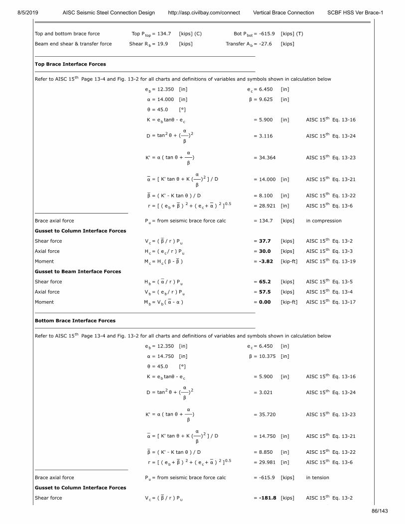
8/5/2019 AISC Seismic Steel Connection Design http://asp.civilbay.com/connect Vertical Brace Connection SCBF HSS Ver Brace-1
86/143
Top and bottom brace force Top P = 134.7 [kips] (C) Bot P = -615.9 [kips] (T)
Beam end shear & transfer force Shear R = 19.9 [kips] Transfer A = -27.6 [kips]
Top Brace Interface Forces
Refer to AISC 15 Page 13-4 and Fig. 13-2 for all charts and definitions of variables and symbols shown in calculation below
e = 12.350 [in] e = 6.450 [in]
α = 14.000 [in] β = 9.625 [in]
θ = 45.0 [°]
K = e tanθ - e = 5.900 [in] AISC 15 Eq. 13-16
D = tan θ + (α
β) = 3.116 AISC 15 Eq. 13-24
K' = α ( tan θ + α
β) = 34.364 AISC 15 Eq. 13-23
α = [ K' tan θ + K (α
β) ] / D = 14.000 [in] AISC 15 Eq. 13-21
β = ( K' - K tan θ ) / D = 8.100 [in] AISC 15 Eq. 13-22
r = [ ( e + β ) + ( e + α ) ] = 28.921 [in] AISC 15 Eq. 13-6
Brace axial force P = from seismic brace force calc = 134.7 [kips] in compression
Gusset to Column Interface Forces
Shear force V = ( β / r ) P = 37.7 [kips] AISC 15 Eq. 13-2
Axial force H = ( e / r ) P = 30.0 [kips] AISC 15 Eq. 13-3
Moment M = H ( β - β ) = -3.82 [kip-ft] AISC 15 Eq. 13-19
Gusset to Beam Interface Forces
Shear force H = ( α / r ) P = 65.2 [kips] AISC 15 Eq. 13-5
Axial force V = ( e / r ) P = 57.5 [kips] AISC 15 Eq. 13-4
Moment M = V ( α - α ) = 0.00 [kip-ft] AISC 15 Eq. 13-17
Bottom Brace Interface Forces
Refer to AISC 15 Page 13-4 and Fig. 13-2 for all charts and definitions of variables and symbols shown in calculation below
e = 12.350 [in] e = 6.450 [in]
α = 14.750 [in] β = 10.375 [in]
θ = 45.0 [°]
K = e tanθ - e = 5.900 [in] AISC 15 Eq. 13-16
D = tan θ + (α
β) = 3.021 AISC 15 Eq. 13-24
K' = α ( tan θ + α
β) = 35.720 AISC 15 Eq. 13-23
α = [ K' tan θ + K (α
β) ] / D = 14.750 [in] AISC 15 Eq. 13-21
β = ( K' - K tan θ ) / D = 8.850 [in] AISC 15 Eq. 13-22
r = [ ( e + β ) + ( e + α ) ] = 29.981 [in] AISC 15 Eq. 13-6
Brace axial force P = from seismic brace force calc = -615.9 [kips] in tension
Gusset to Column Interface Forces
Shear force V = ( β / r ) P = -181.8 [kips] AISC 15 Eq. 13-2
top bot
b b
th
b c
b cth
2 2 th
th
2 th
th
b2
c2 0.5 th
u
c uth
c c uth
c cth
b uth
b b uth
b bth
th
b c
b cth
2 2 th
th
2 th
th
b2
c2 0.5 th
u
c uth
th

8/5/2019 AISC Seismic Steel Connection Design http://asp.civilbay.com/connect Vertical Brace Connection SCBF HSS Ver Brace-1
87/143
Axial force H = ( e / r ) P = -132.5 [kips] AISC 15 Eq. 13-3
Moment M = H ( β - β ) = 16.84 [kip-ft] AISC 15 Eq. 13-19
Gusset to Beam Interface Forces
Shear force H = ( α / r ) P = -303.0 [kips] AISC 15 Eq. 13-5
Axial force V = ( e / r ) P = -253.7 [kips] AISC 15 Eq. 13-4
Moment M = V ( α - α ) = 0.00 [kip-ft] AISC 15 Eq. 13-17
Beam to Column Interface Forces
Beam to Column Interface Shear Force
Beam end shear reaction R = from user input = 19.9 [kips]
Top brace gusset-beam axial force V = = 57.5 [kips] AISC 15 Eq. 13-4
Bot brace gusset-beam axial force V = = -253.7 [kips] AISC 15 Eq. 13-4
Beam to column shear force V = R + V - V = 331.1 [kips] AISC 15 Page 13-4
Beam to Column Interface Axial Force
Top brace gusset-column axial force H = = 30.0 [kips] AISC 15 Eq. 13-3
Bot brace gusset-column axial force H = = -132.5 [kips] AISC 15 Eq. 13-3
Transfer force from adjacent bay A = from user input = -27.6 [kips]
Beam to column axial force P = ( H + H ) x -1 - A = 130.1 [kips] AISC 15 Page 13-4
Beam Member Axial Force
This force is not for use in connection calc. It's output here for user input connection forces equilibrium check only.
P - Beam member axial force is different from P - Beam to column interface axial force as shown above.
P - Beam member axial force is from structural analysis output and cannot be used directly in beam end to column connection design asthis force is interrupted by brace gusset to beam interface force before beam end reaching the column. This force is actually not needed fromuser's input for beam end to column connection design.
P - Beam to column interface axial force is calculated from user's input of brace axial forces and trasnfer force using uniform force method.This force is used in the beam end to column connection design.
P - Beam member axial force is not needed for the beam end to column connection design and is calculated here for verification purposeonly. If it matches the structural analysis output, that means equilibrium is reached and user's input of brace axial forces and trasnfer forceare correct.
Top brace axial force P = from seismic brace force calc = 134.7 [kips] in compression
Top brace to ver line angle θ = from user input = 45.0 [°]
Top brace gusset-column axial force H = from calc shown above = 30.0 [kips] AISC 15 Eq. 13-3
Bot brace axial force P = from seismic brace force calc = -615.9 [kips] in tension
Bot brace to ver line angle θ = from user input = 45.0 [°]
Bot brace gusset-column axial force H = from calc shown above = -132.5 [kips] AISC 15 Eq. 13-3
Beam to column interface axialforce
P = from calc shown above = 130.1 [kips] AISC 15 Page 13-4
Beam member axial force P = (H - P sinθ ) + (H - P sinθ ) = 312.7 [kips] in compression
+ P
Top Brace - Gusset to Column Direct Weld Connection Code=AISC 360-16 LRFD
Result Summary geometries & weld limitations = PASS limit states max ratio = 0.82 PASS
c c uth
c cth
b uth
b b uth
b bth
b
b-topth
b-botth
b-c b b-top b-botth
c-topth
c-botth
b
b-c c-top c-bot bth
bm b-c
bm
b-c
bm
t
t
ctth
b
b
cbth
b-cth
bm ct t t cb b b
b-c
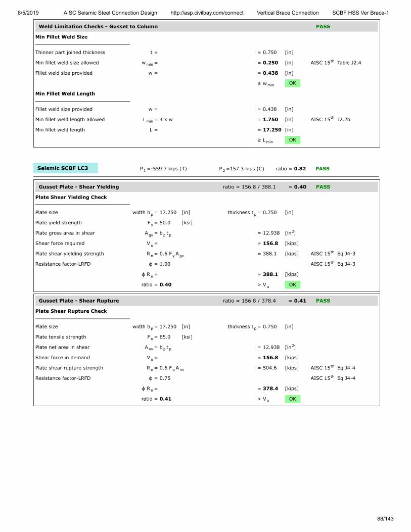
8/5/2019 AISC Seismic Steel Connection Design http://asp.civilbay.com/connect Vertical Brace Connection SCBF HSS Ver Brace-1
88/143
Weld Limitation Checks - Gusset to Column PASS
Min Fillet Weld Size
Thinner part joined thickness t = = 0.750 [in]
Min fillet weld size allowed w = = 0.250 [in] AISC 15 Table J2.4
Fillet weld size provided w = = 0.438 [in]
≥ w OK
Min Fillet Weld Length
Fillet weld size provided w = = 0.438 [in]
Min fillet weld length allowed L = 4 x w = 1.750 [in] AISC 15 J2.2b
Min fillet weld length L = = 17.250 [in]
≥ L OK
Seismic SCBF LC3 P =-559.7 kips (T) P =157.3 kips (C) ratio = 0.82 PASS
Gusset Plate - Shear Yielding ratio = 156.8 / 388.1 = 0.40 PASS
Plate Shear Yielding Check
Plate size width b = 17.250 [in] thickness t = 0.750 [in]
Plate yield strength F = 50.0 [ksi]
Plate gross area in shear A = b t = 12.938 [in ]
Shear force required V = = 156.8 [kips]
Plate shear yielding strength R = 0.6 F A = 388.1 [kips] AISC 15 Eq J4-3
Resistance factor-LRFD φ = 1.00 AISC 15 Eq J4-3
φ R = = 388.1 [kips]
ratio = 0.40 > V OK
Gusset Plate - Shear Rupture ratio = 156.8 / 378.4 = 0.41 PASS
Plate Shear Rupture Check
Plate size width b = 17.250 [in] thickness t = 0.750 [in]
Plate tensile strength F = 65.0 [ksi]
Plate net area in shear A = b t = 12.938 [in ]
Shear force in demand V = = 156.8 [kips]
Plate shear rupture strength R = 0.6 F A = 504.6 [kips] AISC 15 Eq J4-4
Resistance factor-LRFD φ = 0.75 AISC 15 Eq J4-4
φ R = = 378.4 [kips]
ratio = 0.41 > V OK
minth
min
minth
min
1 2
p p
y
gv p p2
u
n y gvth
th
n
u
p p
u
nv p p2
u
n u nvth
th
n
u

8/5/2019 AISC Seismic Steel Connection Design http://asp.civilbay.com/connect Vertical Brace Connection SCBF HSS Ver Brace-1
89/143
Gusset Plate - Axial Tensile Yield ratio = 124.8 / 582.2 = 0.21 PASS
Plate Tensile Yielding Check
Plate size width b = 17.250 [in] thickness t = 0.750 [in]
Plate yield strength F = 50.0 [ksi]
Plate gross area in shear A = b t = 12.938 [in ]
Tensile force required P = = 124.8 [kips]
Plate tensile yielding strength R = F A = 646.9 [kips] AISC 15 Eq J4-1
Resistance factor-LRFD φ = 0.90 AISC 15 Eq J4-1
φ R = = 582.2 [kips]
ratio = 0.21 > P OK
Gusset Plate - Axial Tensile Rupture ratio = 124.8 / 630.7 = 0.20 PASS
Plate Tensile Rupture Check
Plate size width b = 17.250 [in] thickness t = 0.750 [in]
Plate tensile strength F = 65.0 [ksi]
Plate net area in tension A = b t = 12.938 [in ]
Tensile force required P = = 124.8 [kips]
Plate tensile rupture strength R = F A = 840.9 [kips] AISC 15 Eq J4-2
Resistance factor-LRFD φ = 0.75 AISC 15 Eq J4-2
φ R = = 630.7 [kips] AISC 15 Eq J4-2
ratio = 0.20 > P OK
Gusset Plate - Flexural Yield Interact ratio = = 0.25 PASS
Gusset plate width b = 17.250 [in] thick t = 0.750 [in]
yield F = 50.0 [ksi]
Shear plate - gross area A = b x t = 12.938 [in ]
Shear plate - plastic modulus Z = ( b x t ) / 4 = 55.79 [in ]
Flexural strength available M = φ F Z φ=0.90 = 209.22 [kip-ft]
Flexural strength required M = from gusset interface forces calc = 15.86 [kip-ft]
Axial strength available P = from axial tensile yield check = 582.2 [kips]
Axial strength required P = from gusset interface forces calc = -124.8 [kips]
Shear strength available V = from shear yielding check = 388.1 [kips]
Shear strength required V = from gusset interface forces calc = 156.8 [kips]
Flexural yield interaction ratio = ( V
V) + (
P
P +
M
M ) = 0.25 AISC 15 Eq 10-5
< 1.0 OK
p p
y
g p p2
u
n y gth
th
n
u
p p
u
nt p p2
u
n u ntth
th
nth
u
p p
y
g p p2
p p2p
3
c y p
r
c
r
c
r
r
c
2 r
c
r
c
2 th

8/5/2019 AISC Seismic Steel Connection Design http://asp.civilbay.com/connect Vertical Brace Connection SCBF HSS Ver Brace-1
90/143
Gusset Plate - Flexural Rupture Interact ratio = = 0.24 PASS
Gusset plate width b = 17.250 [in] thick t = 0.750 [in]
tensile F = 65.0 [ksi]
Net area of plate A = b x t = 12.938 [in ]
Plastic modulus of net section Z = ( b x t ) / 4 = 55.79 [in ]
Flexural strength available M = φ F Z φ=0.75 = 226.66 [kip-ft]
Flexural strength required M = from gusset interface forces calc = 15.86 [kip-ft]
Axial strength available P = from axial tensile rupture check = 630.7 [kips]
Axial strength required P = from gusset interface forces calc = -124.8 [kips]
Shear strength available V = from shear rupture check = 378.4 [kips]
Shear strength required V = from gusset interface forces calc = 156.8 [kips]
Flexural rupture interaction ratio = ( V
V) + (
P
P +
M
M ) = 0.24 AISC 15 Eq 10-5
< 1.0 OK
Gusset to Column Weld Strength ratio = 14.33 / 17.55 = 0.82 PASS
Gusset to Column Interface - Forces
shear V = 156.8 [kips] axial H = -124.8 [kips] in tension
moment M = 15.86 [kip-ft]
Gusset to Column Interface - Weld Length
Gusset-column fillet weld length L = from user input = 17.250 [in]
Gusset to Column Interface - Combined Weld Stress
Weld stress from axial force f = H / L = -7.235 [kip/in] in tension
Weld stress from shear force f = V / L = 9.090 [kip/in]
Weld stress from moment force f = M
L / 6 = 3.838 [kip/in]
Weld stress combined - max f = [ (f - f ) + f ] = 14.326 [kip/in] AISC 15 Eq 8-11
Weld resultant load angle θ = tan [( f - f ) / f ] = 50.6 [°]
Fillet Weld Strength Calc
Fillet weld leg size w = ⁄ [in] load angle θ = 50.6 [°]
Electrode strength F = 70.0 [ksi] strength coeff C = 1.00 AISC 15 Table 8-3
Number of weld line n = 2 for double fillet
Load angle coefficient C = ( 1 + 0.5 sin θ ) = 1.34 AISC 15 Page 8-9
Fillet weld shear strength R = 0.6 (C x 70 ksi) 0.707 w n C = 34.810 [kip/in] AISC 15 Eq 8-1
Base metal - gusset plate thickness t = 0.750 [in] tensile F = 65.0 [ksi]
Base metal - gusset plate is in shear, shear rupture as per AISC 15 Eq J4-4 is checked AISC 15 J2.4
Base metal shear rupture R = 0.6 F t = 29.250 [kip/in] AISC 15 Eq J4-4
Double fillet linear shear strength R = min ( R , R ) = 29.250 [kip/in] AISC 15 Eq 9-2
Resistance factor-LRFD φ = 0.75 AISC 15 Eq 8-1
φ R = = 21.938 [kip/in]
When gusset plate is directly welded to beam or column, apply 1.25 ductility factorto allow adequate force redistribution in the weld group AISC 15 Page 13-11
Weld strength used for design afterapplying ductility factor
φ R = φ R x ( 1/1.25 ) = 17.550 [kip/in]
ratio = 0.82 > f OK
p p
u
n p p2
net p2p
3
c u net
r
c
r
c
r
r
c
2 r
c
r
c
2 th
c c
c
wc
a c wc
v c wc
b 2
max a b2 2
v0.5 th
-1b a v
716
EXX 1th
21.5 th
n-w 1 2th
u
th th
n-b uth
n n-w n-bth
th
n
th
n n
max

8/5/2019 AISC Seismic Steel Connection Design http://asp.civilbay.com/connect Vertical Brace Connection SCBF HSS Ver Brace-1
91/143
Column Web Local Yielding ratio = 168.9 / 768.6 = 0.22 PASS
Gusset Edge Equivalent Normal Force
Refer to AISC DG29 Fig. B-1 for formula below to calculate gusset edge equivalent normal force
Gusset edge axial force N = = -124.8 [kips]
Gusset edge moment force M = = 15.86 [kip-ft]
Gusset edge interface length L = = 17.250 [in]
Gusset edge equivalent normalforce
N = N - 4 ML = -168.9 [kips] AISC DG29 Fig B-1
Concentrated force from gusset P = = 168.9 [kips]
Column section d = 12.900 [in] t = 0.990 [in]
t = 0.610 [in] k = 1.590 [in]
yield F = 50.0 [ksi]
Length of bearing l = Gusset/Column interface length = 17.250 [in]
Column web local yielding strength R = F t ( 5 k + l ) = 768.6 [kips] AISC 15 Eq J10-2
Resistance factor-LRFD φ = 1.00
φ R = = 768.6 [kips]
ratio = 0.22 > P OK
Column Web Shear Strength ratio = 124.8 / 236.1 = 0.53 PASS
W Shape Column Shear Strength Check
W sect W12X106 d = 12.900 [in] t = 0.610 [in]
F = 50.0 [ksi]
Gusset to column axial force V = from gusset interface force calc = 124.8 [kips]
Column shear strength R = 0.6 F d t = 236.1 [kips] AISC 15 Eq J4-3
Resistance factor-LRFD φ = 1.00 AISC 15 Eq J4-3
φ R = = 236.1 [kips]
ratio = 0.53 > V OK
Seismic SCBF LC4 P =134.7 kips (C) P =-615.9 kips (T) ratio = 0.14 PASS
Gusset Plate - Shear Yielding ratio = 37.7 / 388.1 = 0.10 PASS
Plate Shear Yielding Check
Plate size width b = 17.250 [in] thickness t = 0.750 [in]
Plate yield strength F = 50.0 [ksi]
Plate gross area in shear A = b t = 12.938 [in ]
Shear force required V = = 37.7 [kips]
Plate shear yielding strength R = 0.6 F A = 388.1 [kips] AISC 15 Eq J4-3
Resistance factor-LRFD φ = 1.00 AISC 15 Eq J4-3
φ R = = 388.1 [kips]
ratio = 0.10 > V OK
e
u
f
w
y
b
n y w bth
n
u
w
y
u
n y wth
th
n
u
1 2
p p
y
gv p p2
u
n y gvth
th
n
u

8/5/2019 AISC Seismic Steel Connection Design http://asp.civilbay.com/connect Vertical Brace Connection SCBF HSS Ver Brace-1
92/143
Gusset Plate - Shear Rupture ratio = 37.7 / 378.4 = 0.10 PASS
Plate Shear Rupture Check
Plate size width b = 17.250 [in] thickness t = 0.750 [in]
Plate tensile strength F = 65.0 [ksi]
Plate net area in shear A = b t = 12.938 [in ]
Shear force in demand V = = 37.7 [kips]
Plate shear rupture strength R = 0.6 F A = 504.6 [kips] AISC 15 Eq J4-4
Resistance factor-LRFD φ = 0.75 AISC 15 Eq J4-4
φ R = = 378.4 [kips]
ratio = 0.10 > V OK
Gusset Plate - Axial Yield ratio = 30.0 / 582.2 = 0.05 PASS
Plate Tensile Yielding Check
Plate size width b = 17.250 [in] thickness t = 0.750 [in]
Plate yield strength F = 50.0 [ksi]
Plate gross area in shear A = b t = 12.938 [in ]
Tensile force required P = = 30.0 [kips]
Plate tensile yielding strength R = F A = 646.9 [kips] AISC 15 Eq J4-1
Resistance factor-LRFD φ = 0.90 AISC 15 Eq J4-1
φ R = = 582.2 [kips]
ratio = 0.05 > P OK
Gusset Plate - Flexural Yield Interact ratio = = 0.01 PASS
Gusset plate width b = 17.250 [in] thick t = 0.750 [in]
yield F = 50.0 [ksi]
Shear plate - gross area A = b x t = 12.938 [in ]
Shear plate - plastic modulus Z = ( b x t ) / 4 = 55.79 [in ]
Flexural strength available M = φ F Z φ=0.90 = 209.22 [kip-ft]
Flexural strength required M = from gusset interface forces calc = 3.82 [kip-ft]
Axial strength available P = from axial tensile yield check = 582.2 [kips]
Axial strength required P = from gusset interface forces calc = 30.0 [kips]
Shear strength available V = from shear yielding check = 388.1 [kips]
Shear strength required V = from gusset interface forces calc = 37.7 [kips]
Flexural yield interaction ratio = ( V
V) + (
P
P +
M
M ) = 0.01 AISC 15 Eq 10-5
< 1.0 OK
p p
u
nv p p2
u
n u nvth
th
n
u
p p
y
g p p2
u
n y gth
th
n
u
p p
y
g p p2
p p2p
3
c y p
r
c
r
c
r
r
c
2 r
c
r
c
2 th

8/5/2019 AISC Seismic Steel Connection Design http://asp.civilbay.com/connect Vertical Brace Connection SCBF HSS Ver Brace-1
93/143
Gusset Plate - Flexural Rupture Interact ratio = = 0.01 PASS
Gusset plate width b = 17.250 [in] thick t = 0.750 [in]
tensile F = 65.0 [ksi]
Net area of plate A = b x t = 12.938 [in ]
Plastic modulus of net section Z = ( b x t ) / 4 = 55.79 [in ]
Flexural strength available M = φ F Z φ=0.75 = 226.66 [kip-ft]
Flexural strength required M = from gusset interface forces calc = 3.82 [kip-ft]
Shear strength available V = from shear rupture check = 378.4 [kips]
Shear strength required V = from gusset interface forces calc = 37.7 [kips]
Flexural rupture interaction ratio = ( V
V) + (
M
M ) = 0.01 AISC 15 Eq 10-5
< 1.0 OK
Gusset to Column Weld Strength ratio = 2.19 / 15.59 = 0.14 PASS
Gusset to Column Interface - Forces
shear V = 37.7 [kips] axial H = 30.0 [kips] in compression
moment M = 3.82 [kip-ft]
Gusset to Column Interface - Weld Length
Gusset-column fillet weld length L = from user input = 17.250 [in]
Gusset to Column Interface - Combined Weld Stress
Weld stress from axial force f = H / L = 1.739 [kip/in] in compression
Weld stress from shear force f = V / L = 2.186 [kip/in]
Weld stress from moment force f = M
L / 6 = 0.924 [kip/in]
Weld stress combined - max f = f = 2.186 [kip/in] AISC 15 Eq 8-11
Weld resultant load angle θ = weld only has shear component = 0.0 [°]
Fillet Weld Strength Calc
Fillet weld leg size w = ⁄ [in] load angle θ = 0.0 [°]
Electrode strength F = 70.0 [ksi] strength coeff C = 1.00 AISC 15 Table 8-3
Number of weld line n = 2 for double fillet
Load angle coefficient C = ( 1 + 0.5 sin θ ) = 1.00 AISC 15 Page 8-9
Fillet weld shear strength R = 0.6 (C x 70 ksi) 0.707 w n C = 25.982 [kip/in] AISC 15 Eq 8-1
Base metal - gusset plate thickness t = 0.750 [in] tensile F = 65.0 [ksi]
Base metal - gusset plate is in shear, shear rupture as per AISC 15 Eq J4-4 is checked AISC 15 J2.4
Base metal shear rupture R = 0.6 F t = 29.250 [kip/in] AISC 15 Eq J4-4
Double fillet linear shear strength R = min ( R , R ) = 25.982 [kip/in] AISC 15 Eq 9-2
Resistance factor-LRFD φ = 0.75 AISC 15 Eq 8-1
φ R = = 19.487 [kip/in]
When gusset plate is directly welded to beam or column, apply 1.25 ductility factorto allow adequate force redistribution in the weld group AISC 15 Page 13-11
Weld strength used for design afterapplying ductility factor
φ R = φ R x ( 1/1.25 ) = 15.589 [kip/in]
ratio = 0.14 > f OK
p p
u
n p p2
net p2p
3
c u net
r
c
r
r
c
2 r
c
2 th
c c
c
wc
a c wc
v c wc
b 2
max vth
716
EXX 1th
21.5 th
n-w 1 2th
u
th th
n-b uth
n n-w n-bth
th
n
th
n n
max
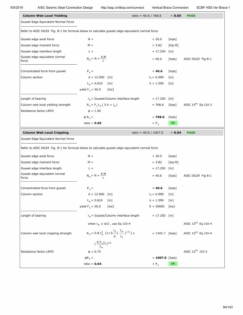
8/5/2019 AISC Seismic Steel Connection Design http://asp.civilbay.com/connect Vertical Brace Connection SCBF HSS Ver Brace-1
94/143
Column Web Local Yielding ratio = 40.6 / 768.6 = 0.05 PASS
Gusset Edge Equivalent Normal Force
Refer to AISC DG29 Fig. B-1 for formula below to calculate gusset edge equivalent normal force
Gusset edge axial force N = = 30.0 [kips]
Gusset edge moment force M = = 3.82 [kip-ft]
Gusset edge interface length L = = 17.250 [in]
Gusset edge equivalent normalforce
N = N + 4 ML = 40.6 [kips] AISC DG29 Fig B-1
Concentrated force from gusset P = = 40.6 [kips]
Column section d = 12.900 [in] t = 0.990 [in]
t = 0.610 [in] k = 1.590 [in]
yield F = 50.0 [ksi]
Length of bearing l = Gusset/Column interface length = 17.250 [in]
Column web local yielding strength R = F t ( 5 k + l ) = 768.6 [kips] AISC 15 Eq J10-2
Resistance factor-LRFD φ = 1.00
φ R = = 768.6 [kips]
ratio = 0.05 > P OK
Column Web Local Crippling ratio = 40.6 / 1007.0 = 0.04 PASS
Gusset Edge Equivalent Normal Force
Refer to AISC DG29 Fig. B-1 for formula below to calculate gusset edge equivalent normal force
Gusset edge axial force N = = 30.0 [kips]
Gusset edge moment force M = = 3.82 [kip-ft]
Gusset edge interface length L = = 17.250 [in]
Gusset edge equivalent normalforce
N = N + 4 ML
= 40.6 [kips] AISC DG29 Fig B-1
Concentrated force from gusset P = = 40.6 [kips]
Column section d = 12.900 [in] t = 0.990 [in]
t = 0.610 [in] k = 1.590 [in]
yield F = 50.0 [ksi] E = 29000 [ksi]
Length of bearing l = Gusset/Column interface length = 17.250 [in]
when l ≥ d/2 , use Eq J10-4 AISC 15 Eq J10-4
Column web local crippling strength R = 0.8 t [1+3l
d(
t
t ) ] x = 1342.7 [kips] AISC 15 Eq J10-4
( E F tt
)
Resistance factor-LRFD φ = 0.75 AISC 15 J10.3
φR = = 1007.0 [kips]
ratio = 0.04 > P OK
e
u
f
w
y
b
n y w bth
n
u
e
u
f
w
y
b
Nth
n2w
b w
f
1.5 th
y f
w
0.5
th
n
u
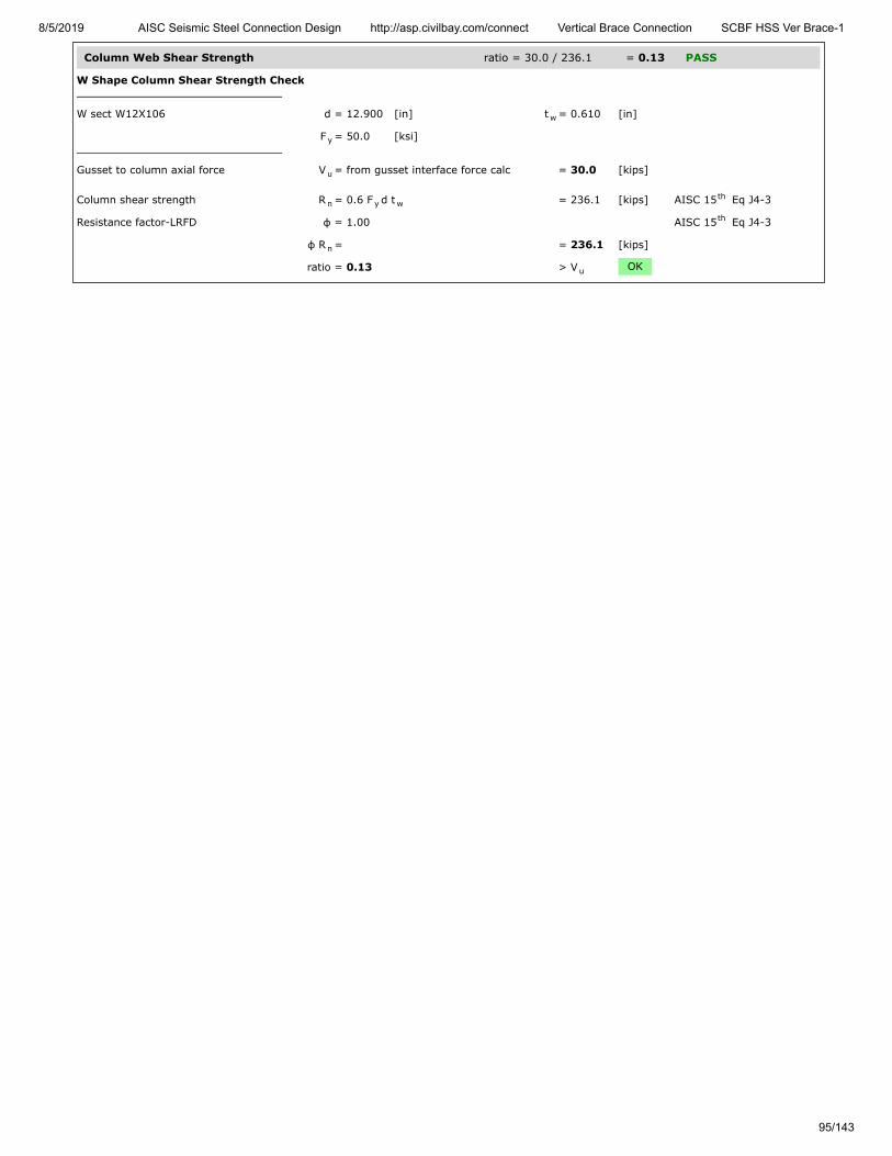
8/5/2019 AISC Seismic Steel Connection Design http://asp.civilbay.com/connect Vertical Brace Connection SCBF HSS Ver Brace-1
95/143
Column Web Shear Strength ratio = 30.0 / 236.1 = 0.13 PASS
W Shape Column Shear Strength Check
W sect W12X106 d = 12.900 [in] t = 0.610 [in]
F = 50.0 [ksi]
Gusset to column axial force V = from gusset interface force calc = 30.0 [kips]
Column shear strength R = 0.6 F d t = 236.1 [kips] AISC 15 Eq J4-3
Resistance factor-LRFD φ = 1.00 AISC 15 Eq J4-3
φ R = = 236.1 [kips]
ratio = 0.13 > V OK
w
y
u
n y wth
th
n
u

8/5/2019 AISC Seismic Steel Connection Design http://asp.civilbay.com/connect Vertical Brace Connection SCBF HSS Ver Brace-1
96/143
Top Brace - Gusset to Beam Direct Weld Connection Code=AISC 360-16 LRFD
Result Summary geometries & weld limitations = PASS limit states max ratio = 0.79 PASS
Brace Weld Limitation Checks - Gusset to Beam PASS
Min Fillet Weld Size
Thinner part joined thickness t = = 0.750 [in]
Min fillet weld size allowed w = = 0.250 [in] AISC 15 Table J2.4
Fillet weld size provided w = = 0.438 [in]
≥ w OK
Min Fillet Weld Length
Fillet weld size provided w = = 0.438 [in]
Min fillet weld length allowed L = 4 x w = 1.750 [in] AISC 15 J2.2b
Min fillet weld length L = = 26.000 [in]
≥ L OK
Seismic SCBF LC3 P =-559.7 kips (T) P =157.3 kips (C) ratio = 0.79 PASS
Gusset Plate - Shear Yielding ratio = 270.9 / 585.0 = 0.46 PASS
Plate Shear Yielding Check
Plate size width b = 26.000 [in] thickness t = 0.750 [in]
Plate yield strength F = 50.0 [ksi]
Plate gross area in shear A = b t = 19.500 [in ]
Shear force required V = = 270.9 [kips]
Plate shear yielding strength R = 0.6 F A = 585.0 [kips] AISC 15 Eq J4-3
Resistance factor-LRFD φ = 1.00 AISC 15 Eq J4-3
φ R = = 585.0 [kips]
ratio = 0.46 > V OK
Gusset Plate - Shear Rupture ratio = 270.9 / 570.4 = 0.47 PASS
Plate Shear Rupture Check
Plate size width b = 26.000 [in] thickness t = 0.750 [in]
Plate tensile strength F = 65.0 [ksi]
Plate net area in shear A = b t = 19.500 [in ]
Shear force in demand V = = 270.9 [kips]
Plate shear rupture strength R = 0.6 F A = 760.5 [kips] AISC 15 Eq J4-4
Resistance factor-LRFD φ = 0.75 AISC 15 Eq J4-4
φ R = = 570.4 [kips]
ratio = 0.47 > V OK
minth
min
minth
min
1 2
p p
y
gv p p2
u
n y gvth
th
n
u
p p
u
nv p p2
u
n u nvth
th
n
u
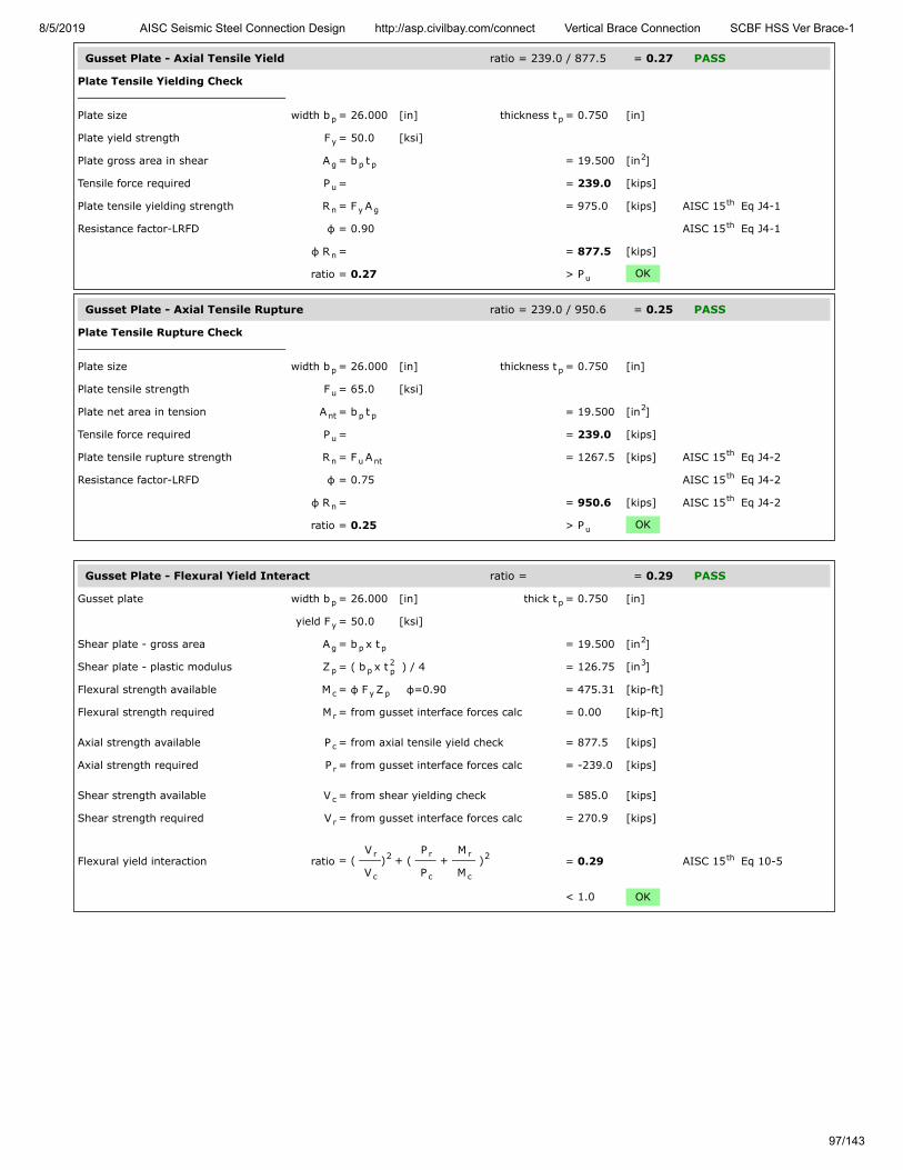
8/5/2019 AISC Seismic Steel Connection Design http://asp.civilbay.com/connect Vertical Brace Connection SCBF HSS Ver Brace-1
97/143
Gusset Plate - Axial Tensile Yield ratio = 239.0 / 877.5 = 0.27 PASS
Plate Tensile Yielding Check
Plate size width b = 26.000 [in] thickness t = 0.750 [in]
Plate yield strength F = 50.0 [ksi]
Plate gross area in shear A = b t = 19.500 [in ]
Tensile force required P = = 239.0 [kips]
Plate tensile yielding strength R = F A = 975.0 [kips] AISC 15 Eq J4-1
Resistance factor-LRFD φ = 0.90 AISC 15 Eq J4-1
φ R = = 877.5 [kips]
ratio = 0.27 > P OK
Gusset Plate - Axial Tensile Rupture ratio = 239.0 / 950.6 = 0.25 PASS
Plate Tensile Rupture Check
Plate size width b = 26.000 [in] thickness t = 0.750 [in]
Plate tensile strength F = 65.0 [ksi]
Plate net area in tension A = b t = 19.500 [in ]
Tensile force required P = = 239.0 [kips]
Plate tensile rupture strength R = F A = 1267.5 [kips] AISC 15 Eq J4-2
Resistance factor-LRFD φ = 0.75 AISC 15 Eq J4-2
φ R = = 950.6 [kips] AISC 15 Eq J4-2
ratio = 0.25 > P OK
Gusset Plate - Flexural Yield Interact ratio = = 0.29 PASS
Gusset plate width b = 26.000 [in] thick t = 0.750 [in]
yield F = 50.0 [ksi]
Shear plate - gross area A = b x t = 19.500 [in ]
Shear plate - plastic modulus Z = ( b x t ) / 4 = 126.75 [in ]
Flexural strength available M = φ F Z φ=0.90 = 475.31 [kip-ft]
Flexural strength required M = from gusset interface forces calc = 0.00 [kip-ft]
Axial strength available P = from axial tensile yield check = 877.5 [kips]
Axial strength required P = from gusset interface forces calc = -239.0 [kips]
Shear strength available V = from shear yielding check = 585.0 [kips]
Shear strength required V = from gusset interface forces calc = 270.9 [kips]
Flexural yield interaction ratio = ( V
V) + (
P
P +
M
M ) = 0.29 AISC 15 Eq 10-5
< 1.0 OK
p p
y
g p p2
u
n y gth
th
n
u
p p
u
nt p p2
u
n u ntth
th
nth
u
p p
y
g p p2
p p2p
3
c y p
r
c
r
c
r
r
c
2 r
c
r
c
2 th
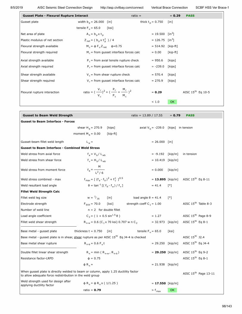
8/5/2019 AISC Seismic Steel Connection Design http://asp.civilbay.com/connect Vertical Brace Connection SCBF HSS Ver Brace-1
98/143
Gusset Plate - Flexural Rupture Interact ratio = = 0.29 PASS
Gusset plate width b = 26.000 [in] thick t = 0.750 [in]
tensile F = 65.0 [ksi]
Net area of plate A = b x t = 19.500 [in ]
Plastic modulus of net section Z = ( b x t ) / 4 = 126.75 [in ]
Flexural strength available M = φ F Z φ=0.75 = 514.92 [kip-ft]
Flexural strength required M = from gusset interface forces calc = 0.00 [kip-ft]
Axial strength available P = from axial tensile rupture check = 950.6 [kips]
Axial strength required P = from gusset interface forces calc = -239.0 [kips]
Shear strength available V = from shear rupture check = 570.4 [kips]
Shear strength required V = from gusset interface forces calc = 270.9 [kips]
Flexural rupture interaction ratio = ( V
V) + (
P
P +
M
M ) = 0.29 AISC 15 Eq 10-5
< 1.0 OK
Gusset to Beam Weld Strength ratio = 13.89 / 17.55 = 0.79 PASS
Gusset to Beam Interface - Forces
shear H = 270.9 [kips] axial V = -239.0 [kips] in tension
moment M = 0.00 [kip-ft]
Gusset-beam fillet weld length L = = 26.000 [in]
Gusset to Beam Interface - Combined Weld Stress
Weld stress from axial force f = V / L = -9.192 [kip/in] in tension
Weld stress from shear force f = H / L = 10.419 [kip/in]
Weld stress from moment force f = M
L / 6 = 0.000 [kip/in]
Weld stress combined - max f = [ (f - f ) + f ] = 13.895 [kip/in] AISC 15 Eq 8-11
Weld resultant load angle θ = tan [( f - f ) / f ] = 41.4 [°]
Fillet Weld Strength Calc
Fillet weld leg size w = ⁄ [in] load angle θ = 41.4 [°]
Electrode strength F = 70.0 [ksi] strength coeff C = 1.00 AISC 15 Table 8-3
Number of weld line n = 2 for double fillet
Load angle coefficient C = ( 1 + 0.5 sin θ ) = 1.27 AISC 15 Page 8-9
Fillet weld shear strength R = 0.6 (C x 70 ksi) 0.707 w n C = 32.973 [kip/in] AISC 15 Eq 8-1
Base metal - gusset plate thickness t = 0.750 [in] tensile F = 65.0 [ksi]
Base metal - gusset plate is in shear, shear rupture as per AISC 15 Eq J4-4 is checked AISC 15 J2.4
Base metal shear rupture R = 0.6 F t = 29.250 [kip/in] AISC 15 Eq J4-4
Double fillet linear shear strength R = min ( R , R ) = 29.250 [kip/in] AISC 15 Eq 9-2
Resistance factor-LRFD φ = 0.75 AISC 15 Eq 8-1
φ R = = 21.938 [kip/in]
When gusset plate is directly welded to beam or column, apply 1.25 ductility factorto allow adequate force redistribution in the weld group AISC 15 Page 13-11
Weld strength used for design afterapplying ductility factor
φ R = φ R x ( 1/1.25 ) = 17.550 [kip/in]
ratio = 0.79 > f OK
p p
u
n p p2
net p2p
3
c u net
r
c
r
c
r
r
c
2 r
c
r
c
2 th
b b
b
w
a b wb
v b wb
b 2
max a b2 2
v0.5 th
-1b a v
716
EXX 1th
21.5 th
n-w 1 2th
u
th th
n-b uth
n n-w n-bth
th
n
th
n n
max
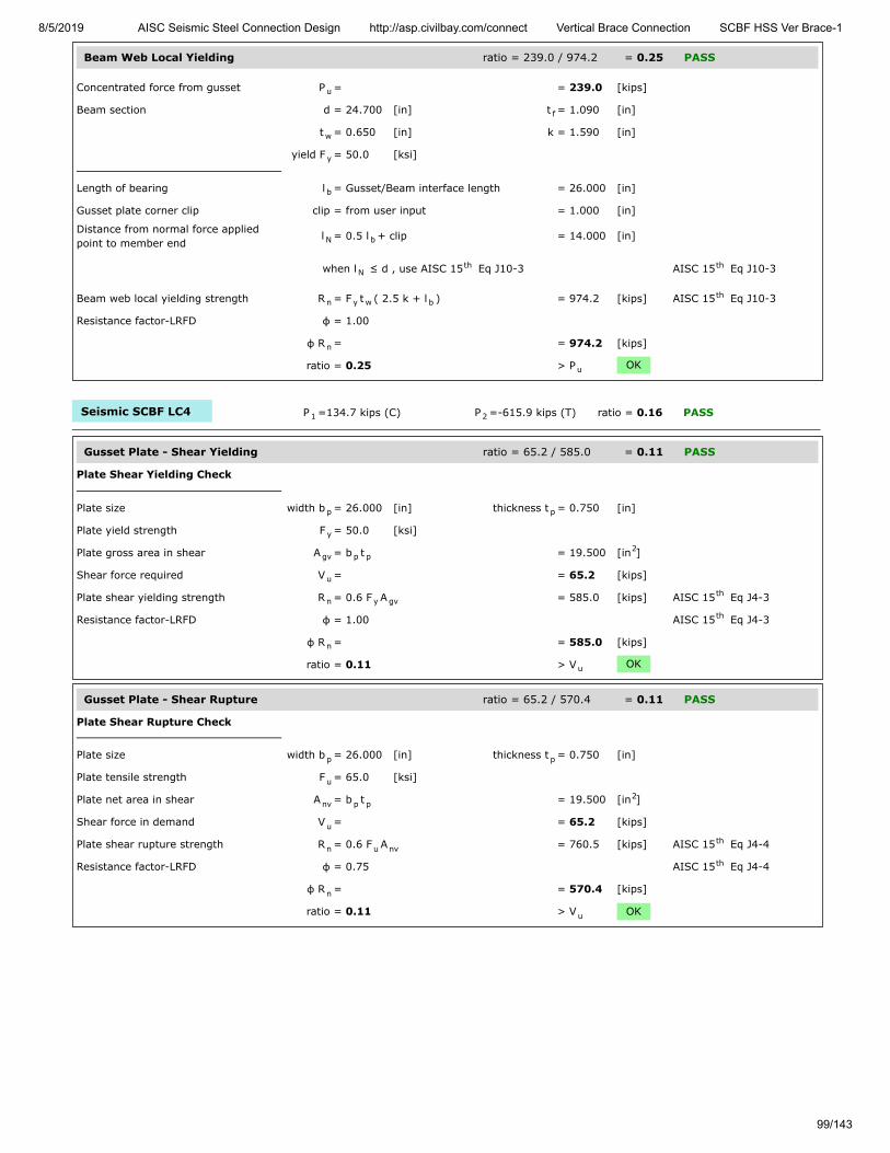
8/5/2019 AISC Seismic Steel Connection Design http://asp.civilbay.com/connect Vertical Brace Connection SCBF HSS Ver Brace-1
99/143
Beam Web Local Yielding ratio = 239.0 / 974.2 = 0.25 PASS
Concentrated force from gusset P = = 239.0 [kips]
Beam section d = 24.700 [in] t = 1.090 [in]
t = 0.650 [in] k = 1.590 [in]
yield F = 50.0 [ksi]
Length of bearing l = Gusset/Beam interface length = 26.000 [in]
Gusset plate corner clip clip = from user input = 1.000 [in]
Distance from normal force appliedpoint to member end
l = 0.5 l + clip = 14.000 [in]
when l ≤ d , use AISC 15 Eq J10-3 AISC 15 Eq J10-3
Beam web local yielding strength R = F t ( 2.5 k + l ) = 974.2 [kips] AISC 15 Eq J10-3
Resistance factor-LRFD φ = 1.00
φ R = = 974.2 [kips]
ratio = 0.25 > P OK
Seismic SCBF LC4 P =134.7 kips (C) P =-615.9 kips (T) ratio = 0.16 PASS
Gusset Plate - Shear Yielding ratio = 65.2 / 585.0 = 0.11 PASS
Plate Shear Yielding Check
Plate size width b = 26.000 [in] thickness t = 0.750 [in]
Plate yield strength F = 50.0 [ksi]
Plate gross area in shear A = b t = 19.500 [in ]
Shear force required V = = 65.2 [kips]
Plate shear yielding strength R = 0.6 F A = 585.0 [kips] AISC 15 Eq J4-3
Resistance factor-LRFD φ = 1.00 AISC 15 Eq J4-3
φ R = = 585.0 [kips]
ratio = 0.11 > V OK
Gusset Plate - Shear Rupture ratio = 65.2 / 570.4 = 0.11 PASS
Plate Shear Rupture Check
Plate size width b = 26.000 [in] thickness t = 0.750 [in]
Plate tensile strength F = 65.0 [ksi]
Plate net area in shear A = b t = 19.500 [in ]
Shear force in demand V = = 65.2 [kips]
Plate shear rupture strength R = 0.6 F A = 760.5 [kips] AISC 15 Eq J4-4
Resistance factor-LRFD φ = 0.75 AISC 15 Eq J4-4
φ R = = 570.4 [kips]
ratio = 0.11 > V OK
u
f
w
y
b
N b
Nth th
n y w bth
n
u
1 2
p p
y
gv p p2
u
n y gvth
th
n
u
p p
u
nv p p2
u
n u nvth
th
n
u
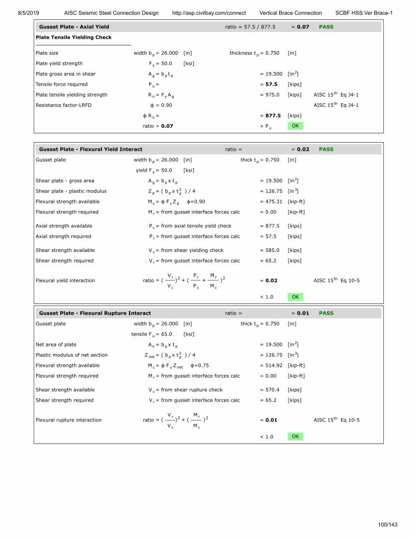
8/5/2019 AISC Seismic Steel Connection Design http://asp.civilbay.com/connect Vertical Brace Connection SCBF HSS Ver Brace-1
100/143
Gusset Plate - Axial Yield ratio = 57.5 / 877.5 = 0.07 PASS
Plate Tensile Yielding Check
Plate size width b = 26.000 [in] thickness t = 0.750 [in]
Plate yield strength F = 50.0 [ksi]
Plate gross area in shear A = b t = 19.500 [in ]
Tensile force required P = = 57.5 [kips]
Plate tensile yielding strength R = F A = 975.0 [kips] AISC 15 Eq J4-1
Resistance factor-LRFD φ = 0.90 AISC 15 Eq J4-1
φ R = = 877.5 [kips]
ratio = 0.07 > P OK
Gusset Plate - Flexural Yield Interact ratio = = 0.02 PASS
Gusset plate width b = 26.000 [in] thick t = 0.750 [in]
yield F = 50.0 [ksi]
Shear plate - gross area A = b x t = 19.500 [in ]
Shear plate - plastic modulus Z = ( b x t ) / 4 = 126.75 [in ]
Flexural strength available M = φ F Z φ=0.90 = 475.31 [kip-ft]
Flexural strength required M = from gusset interface forces calc = 0.00 [kip-ft]
Axial strength available P = from axial tensile yield check = 877.5 [kips]
Axial strength required P = from gusset interface forces calc = 57.5 [kips]
Shear strength available V = from shear yielding check = 585.0 [kips]
Shear strength required V = from gusset interface forces calc = 65.2 [kips]
Flexural yield interaction ratio = ( V
V) + (
P
P +
M
M ) = 0.02 AISC 15 Eq 10-5
< 1.0 OK
Gusset Plate - Flexural Rupture Interact ratio = = 0.01 PASS
Gusset plate width b = 26.000 [in] thick t = 0.750 [in]
tensile F = 65.0 [ksi]
Net area of plate A = b x t = 19.500 [in ]
Plastic modulus of net section Z = ( b x t ) / 4 = 126.75 [in ]
Flexural strength available M = φ F Z φ=0.75 = 514.92 [kip-ft]
Flexural strength required M = from gusset interface forces calc = 0.00 [kip-ft]
Shear strength available V = from shear rupture check = 570.4 [kips]
Shear strength required V = from gusset interface forces calc = 65.2 [kips]
Flexural rupture interaction ratio = ( V
V) + (
M
M ) = 0.01 AISC 15 Eq 10-5
< 1.0 OK
p p
y
g p p2
u
n y gth
th
n
u
p p
y
g p p2
p p2p
3
c y p
r
c
r
c
r
r
c
2 r
c
r
c
2 th
p p
u
n p p2
net p2p
3
c u net
r
c
r
r
c
2 r
c
2 th

8/5/2019 AISC Seismic Steel Connection Design http://asp.civilbay.com/connect Vertical Brace Connection SCBF HSS Ver Brace-1
101/143
Gusset to Beam Weld Strength ratio = 2.51 / 15.59 = 0.16 PASS
Gusset to Beam Interface - Forces
shear H = 65.2 [kips] axial V = 57.5 [kips] in compression
moment M = 0.00 [kip-ft]
Gusset-beam fillet weld length L = = 26.000 [in]
Gusset to Beam Interface - Combined Weld Stress
Weld stress from axial force f = V / L = 0.000 [kip/in] in compression
Weld stress from shear force f = H / L = 2.508 [kip/in]
Weld stress from moment force f = M
L / 6 = 0.000 [kip/in]
Weld stress combined - max f = f = 2.508 [kip/in] AISC 15 Eq 8-11
Weld resultant load angle θ = weld only has shear component = 0.0 [°]
Fillet Weld Strength Calc
Fillet weld leg size w = ⁄ [in] load angle θ = 0.0 [°]
Electrode strength F = 70.0 [ksi] strength coeff C = 1.00 AISC 15 Table 8-3
Number of weld line n = 2 for double fillet
Load angle coefficient C = ( 1 + 0.5 sin θ ) = 1.00 AISC 15 Page 8-9
Fillet weld shear strength R = 0.6 (C x 70 ksi) 0.707 w n C = 25.982 [kip/in] AISC 15 Eq 8-1
Base metal - gusset plate thickness t = 0.750 [in] tensile F = 65.0 [ksi]
Base metal - gusset plate is in shear, shear rupture as per AISC 15 Eq J4-4 is checked AISC 15 J2.4
Base metal shear rupture R = 0.6 F t = 29.250 [kip/in] AISC 15 Eq J4-4
Double fillet linear shear strength R = min ( R , R ) = 25.982 [kip/in] AISC 15 Eq 9-2
Resistance factor-LRFD φ = 0.75 AISC 15 Eq 8-1
φ R = = 19.487 [kip/in]
When gusset plate is directly welded to beam or column, apply 1.25 ductility factorto allow adequate force redistribution in the weld group AISC 15 Page 13-11
Weld strength used for design afterapplying ductility factor
φ R = φ R x ( 1/1.25 ) = 15.589 [kip/in]
ratio = 0.16 > f OK
Beam Web Local Yielding ratio = 57.5 / 974.2 = 0.06 PASS
Concentrated force from gusset P = = 57.5 [kips]
Beam section d = 24.700 [in] t = 1.090 [in]
t = 0.650 [in] k = 1.590 [in]
yield F = 50.0 [ksi]
Length of bearing l = Gusset/Beam interface length = 26.000 [in]
Gusset plate corner clip clip = from user input = 1.000 [in]
Distance from normal force appliedpoint to member end
l = 0.5 l + clip = 14.000 [in]
when l ≤ d , use AISC 15 Eq J10-3 AISC 15 Eq J10-3
Beam web local yielding strength R = F t ( 2.5 k + l ) = 974.2 [kips] AISC 15 Eq J10-3
Resistance factor-LRFD φ = 1.00
φ R = = 974.2 [kips]
ratio = 0.06 > P OK
b b
b
w
a b wb
v b wb
b 2
max vth
716
EXX 1th
21.5 th
n-w 1 2th
u
th th
n-b uth
n n-w n-bth
th
n
th
n n
max
u
f
w
y
b
N b
Nth th
n y w bth
n
u
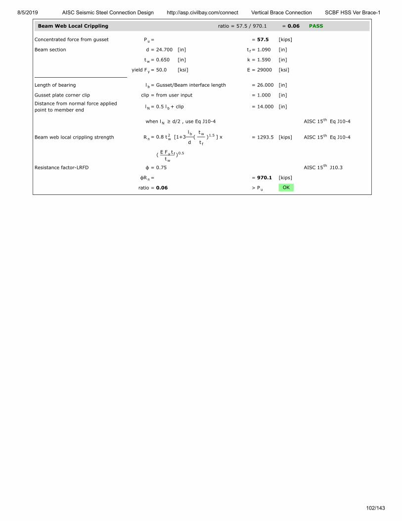
8/5/2019 AISC Seismic Steel Connection Design http://asp.civilbay.com/connect Vertical Brace Connection SCBF HSS Ver Brace-1
102/143
Beam Web Local Crippling ratio = 57.5 / 970.1 = 0.06 PASS
Concentrated force from gusset P = = 57.5 [kips]
Beam section d = 24.700 [in] t = 1.090 [in]
t = 0.650 [in] k = 1.590 [in]
yield F = 50.0 [ksi] E = 29000 [ksi]
Length of bearing l = Gusset/Beam interface length = 26.000 [in]
Gusset plate corner clip clip = from user input = 1.000 [in]
Distance from normal force appliedpoint to member end
l = 0.5 l + clip = 14.000 [in]
when l ≥ d/2 , use Eq J10-4 AISC 15 Eq J10-4
Beam web local crippling strength R = 0.8 t [1+3l
d(
t
t ) ] x = 1293.5 [kips] AISC 15 Eq J10-4
( E F tt
)
Resistance factor-LRFD φ = 0.75 AISC 15 J10.3
φR = = 970.1 [kips]
ratio = 0.06 > P OK
u
f
w
y
b
N b
Nth
n2w
b w
f
1.5 th
y f
w
0.5
th
n
u

8/5/2019 AISC Seismic Steel Connection Design http://asp.civilbay.com/connect Vertical Brace Connection SCBF HSS Ver Brace-1
103/143
Bot Brace - Gusset to Column Direct Weld Connection Code=AISC 360-16 LRFD
Result Summary geometries & weld limitations = PASS limit states max ratio = 0.98 PASS
Weld Limitation Checks - Gusset to Column PASS
Min Fillet Weld Size
Thinner part joined thickness t = = 0.750 [in]
Min fillet weld size allowed w = = 0.250 [in] AISC 15 Table J2.4
Fillet weld size provided w = = 0.313 [in]
≥ w OK
Min Fillet Weld Length
Fillet weld size provided w = = 0.313 [in]
Min fillet weld length allowed L = 4 x w = 1.250 [in] AISC 15 J2.2b
Min fillet weld length L = = 18.750 [in]
≥ L OK
Seismic SCBF LC3 P =-559.7 kips (T) P =157.3 kips (C) ratio = 0.22 PASS
Gusset Plate - Shear Yielding ratio = 46.4 / 421.9 = 0.11 PASS
Plate Shear Yielding Check
Plate size width b = 18.750 [in] thickness t = 0.750 [in]
Plate yield strength F = 50.0 [ksi]
Plate gross area in shear A = b t = 14.063 [in ]
Shear force required V = = 46.4 [kips]
Plate shear yielding strength R = 0.6 F A = 421.9 [kips] AISC 15 Eq J4-3
Resistance factor-LRFD φ = 1.00 AISC 15 Eq J4-3
φ R = = 421.9 [kips]
ratio = 0.11 > V OK
Gusset Plate - Shear Rupture ratio = 46.4 / 411.3 = 0.11 PASS
Plate Shear Rupture Check
Plate size width b = 18.750 [in] thickness t = 0.750 [in]
Plate tensile strength F = 65.0 [ksi]
Plate net area in shear A = b t = 14.063 [in ]
Shear force in demand V = = 46.4 [kips]
Plate shear rupture strength R = 0.6 F A = 548.4 [kips] AISC 15 Eq J4-4
Resistance factor-LRFD φ = 0.75 AISC 15 Eq J4-4
φ R = = 411.3 [kips]
ratio = 0.11 > V OK
minth
min
minth
min
1 2
p p
y
gv p p2
u
n y gvth
th
n
u
p p
u
nv p p2
u
n u nvth
th
n
u

8/5/2019 AISC Seismic Steel Connection Design http://asp.civilbay.com/connect Vertical Brace Connection SCBF HSS Ver Brace-1
104/143
Gusset Plate - Axial Tensile Yield ratio = 33.8 / 632.8 = 0.05 PASS
Plate Tensile Yielding Check
Plate size width b = 18.750 [in] thickness t = 0.750 [in]
Plate yield strength F = 50.0 [ksi]
Plate gross area in shear A = b t = 14.063 [in ]
Tensile force required P = = 33.8 [kips]
Plate tensile yielding strength R = F A = 703.1 [kips] AISC 15 Eq J4-1
Resistance factor-LRFD φ = 0.90 AISC 15 Eq J4-1
φ R = = 632.8 [kips]
ratio = 0.05 > P OK
Gusset Plate - Axial Tensile Rupture ratio = 33.8 / 685.5 = 0.05 PASS
Plate Tensile Rupture Check
Plate size width b = 18.750 [in] thickness t = 0.750 [in]
Plate tensile strength F = 65.0 [ksi]
Plate net area in tension A = b t = 14.063 [in ]
Tensile force required P = = 33.8 [kips]
Plate tensile rupture strength R = F A = 914.1 [kips] AISC 15 Eq J4-2
Resistance factor-LRFD φ = 0.75 AISC 15 Eq J4-2
φ R = = 685.5 [kips] AISC 15 Eq J4-2
ratio = 0.05 > P OK
Gusset Plate - Flexural Yield Interact ratio = = 0.01 PASS
Gusset plate width b = 18.750 [in] thick t = 0.750 [in]
yield F = 50.0 [ksi]
Shear plate - gross area A = b x t = 14.063 [in ]
Shear plate - plastic modulus Z = ( b x t ) / 4 = 65.92 [in ]
Flexural strength available M = φ F Z φ=0.90 = 247.19 [kip-ft]
Flexural strength required M = from gusset interface forces calc = 4.30 [kip-ft]
Axial strength available P = from axial tensile yield check = 632.8 [kips]
Axial strength required P = from gusset interface forces calc = 33.8 [kips]
Shear strength available V = from shear yielding check = 421.9 [kips]
Shear strength required V = from gusset interface forces calc = 46.4 [kips]
Flexural yield interaction ratio = ( V
V) + (
P
P +
M
M ) = 0.01 AISC 15 Eq 10-5
< 1.0 OK
p p
y
g p p2
u
n y gth
th
n
u
p p
u
nt p p2
u
n u ntth
th
nth
u
p p
y
g p p2
p p2p
3
c y p
r
c
r
c
r
r
c
2 r
c
r
c
2 th

8/5/2019 AISC Seismic Steel Connection Design http://asp.civilbay.com/connect Vertical Brace Connection SCBF HSS Ver Brace-1
105/143
Gusset Plate - Flexural Rupture Interact ratio = = 0.01 PASS
Gusset plate width b = 18.750 [in] thick t = 0.750 [in]
tensile F = 65.0 [ksi]
Net area of plate A = b x t = 14.063 [in ]
Plastic modulus of net section Z = ( b x t ) / 4 = 65.92 [in ]
Flexural strength available M = φ F Z φ=0.75 = 267.79 [kip-ft]
Flexural strength required M = from gusset interface forces calc = 4.30 [kip-ft]
Axial strength available P = from axial tensile rupture check = 685.5 [kips]
Axial strength required P = from gusset interface forces calc = 33.8 [kips]
Shear strength available V = from shear rupture check = 411.3 [kips]
Shear strength required V = from gusset interface forces calc = 46.4 [kips]
Flexural rupture interaction ratio = ( V
V) + (
P
P +
M
M ) = 0.01 AISC 15 Eq 10-5
< 1.0 OK
Gusset to Column Weld Strength ratio = 2.47 / 11.14 = 0.22 PASS
Gusset to Column Interface - Forces
shear V = 46.4 [kips] axial H = 33.8 [kips] in compression
moment M = 4.30 [kip-ft]
Gusset to Column Interface - Weld Length
Gusset-column fillet weld length L = from user input = 18.750 [in]
Gusset to Column Interface - Combined Weld Stress
Weld stress from axial force f = H / L = 1.803 [kip/in] in compression
Weld stress from shear force f = V / L = 2.475 [kip/in]
Weld stress from moment force f = M
L / 6 = 0.881 [kip/in]
Weld stress combined - max f = f = 2.475 [kip/in] AISC 15 Eq 8-11
Weld resultant load angle θ = weld only has shear component = 0.0 [°]
Fillet Weld Strength Calc
Fillet weld leg size w = ⁄ [in] load angle θ = 0.0 [°]
Electrode strength F = 70.0 [ksi] strength coeff C = 1.00 AISC 15 Table 8-3
Number of weld line n = 2 for double fillet
Load angle coefficient C = ( 1 + 0.5 sin θ ) = 1.00 AISC 15 Page 8-9
Fillet weld shear strength R = 0.6 (C x 70 ksi) 0.707 w n C = 18.559 [kip/in] AISC 15 Eq 8-1
Base metal - gusset plate thickness t = 0.750 [in] tensile F = 65.0 [ksi]
Base metal - gusset plate is in shear, shear rupture as per AISC 15 Eq J4-4 is checked AISC 15 J2.4
Base metal shear rupture R = 0.6 F t = 29.250 [kip/in] AISC 15 Eq J4-4
Double fillet linear shear strength R = min ( R , R ) = 18.559 [kip/in] AISC 15 Eq 9-2
Resistance factor-LRFD φ = 0.75 AISC 15 Eq 8-1
φ R = = 13.919 [kip/in]
When gusset plate is directly welded to beam or column, apply 1.25 ductility factorto allow adequate force redistribution in the weld group AISC 15 Page 13-11
Weld strength used for design afterapplying ductility factor
φ R = φ R x ( 1/1.25 ) = 11.135 [kip/in]
ratio = 0.22 > f OK
p p
u
n p p2
net p2p
3
c u net
r
c
r
c
r
r
c
2 r
c
r
c
2 th
c c
c
wc
a c wc
v c wc
b 2
max vth
516
EXX 1th
21.5 th
n-w 1 2th
u
th th
n-b uth
n n-w n-bth
th
n
th
n n
max

8/5/2019 AISC Seismic Steel Connection Design http://asp.civilbay.com/connect Vertical Brace Connection SCBF HSS Ver Brace-1
106/143
Column Web Local Yielding ratio = 44.8 / 814.4 = 0.06 PASS
Gusset Edge Equivalent Normal Force
Refer to AISC DG29 Fig. B-1 for formula below to calculate gusset edge equivalent normal force
Gusset edge axial force N = = 33.8 [kips]
Gusset edge moment force M = = 4.30 [kip-ft]
Gusset edge interface length L = = 18.750 [in]
Gusset edge equivalent normalforce
N = N + 4 ML = 44.8 [kips] AISC DG29 Fig B-1
Concentrated force from gusset P = = 44.8 [kips]
Column section d = 12.900 [in] t = 0.990 [in]
t = 0.610 [in] k = 1.590 [in]
yield F = 50.0 [ksi]
Length of bearing l = Gusset/Column interface length = 18.750 [in]
Column web local yielding strength R = F t ( 5 k + l ) = 814.4 [kips] AISC 15 Eq J10-2
Resistance factor-LRFD φ = 1.00
φ R = = 814.4 [kips]
ratio = 0.06 > P OK
Column Web Local Crippling ratio = 44.8 / 1064.8 = 0.04 PASS
Gusset Edge Equivalent Normal Force
Refer to AISC DG29 Fig. B-1 for formula below to calculate gusset edge equivalent normal force
Gusset edge axial force N = = 33.8 [kips]
Gusset edge moment force M = = 4.30 [kip-ft]
Gusset edge interface length L = = 18.750 [in]
Gusset edge equivalent normalforce
N = N + 4 ML
= 44.8 [kips] AISC DG29 Fig B-1
Concentrated force from gusset P = = 44.8 [kips]
Column section d = 12.900 [in] t = 0.990 [in]
t = 0.610 [in] k = 1.590 [in]
yield F = 50.0 [ksi] E = 29000 [ksi]
Length of bearing l = Gusset/Column interface length = 18.750 [in]
when l ≥ d/2 , use Eq J10-4 AISC 15 Eq J10-4
Column web local crippling strength R = 0.8 t [1+3l
d(
t
t ) ] x = 1419.7 [kips] AISC 15 Eq J10-4
( E F tt
)
Resistance factor-LRFD φ = 0.75 AISC 15 J10.3
φR = = 1064.8 [kips]
ratio = 0.04 > P OK
e
u
f
w
y
b
n y w bth
n
u
e
u
f
w
y
b
Nth
n2w
b w
f
1.5 th
y f
w
0.5
th
n
u

8/5/2019 AISC Seismic Steel Connection Design http://asp.civilbay.com/connect Vertical Brace Connection SCBF HSS Ver Brace-1
107/143
Column Web Shear Strength ratio = 33.8 / 236.1 = 0.14 PASS
W Shape Column Shear Strength Check
W sect W12X106 d = 12.900 [in] t = 0.610 [in]
F = 50.0 [ksi]
Gusset to column axial force V = from gusset interface force calc = 33.8 [kips]
Column shear strength R = 0.6 F d t = 236.1 [kips] AISC 15 Eq J4-3
Resistance factor-LRFD φ = 1.00 AISC 15 Eq J4-3
φ R = = 236.1 [kips]
ratio = 0.14 > V OK
Seismic SCBF LC4 P =134.7 kips (C) P =-615.9 kips (T) ratio = 0.98 PASS
Gusset Plate - Shear Yielding ratio = 181.8 / 421.9 = 0.43 PASS
Plate Shear Yielding Check
Plate size width b = 18.750 [in] thickness t = 0.750 [in]
Plate yield strength F = 50.0 [ksi]
Plate gross area in shear A = b t = 14.063 [in ]
Shear force required V = = 181.8 [kips]
Plate shear yielding strength R = 0.6 F A = 421.9 [kips] AISC 15 Eq J4-3
Resistance factor-LRFD φ = 1.00 AISC 15 Eq J4-3
φ R = = 421.9 [kips]
ratio = 0.43 > V OK
Gusset Plate - Shear Rupture ratio = 181.8 / 411.3 = 0.44 PASS
Plate Shear Rupture Check
Plate size width b = 18.750 [in] thickness t = 0.750 [in]
Plate tensile strength F = 65.0 [ksi]
Plate net area in shear A = b t = 14.063 [in ]
Shear force in demand V = = 181.8 [kips]
Plate shear rupture strength R = 0.6 F A = 548.4 [kips] AISC 15 Eq J4-4
Resistance factor-LRFD φ = 0.75 AISC 15 Eq J4-4
φ R = = 411.3 [kips]
ratio = 0.44 > V OK
Gusset Plate - Axial Yield ratio = 132.5 / 632.8 = 0.21 PASS
Plate Tensile Yielding Check
Plate size width b = 18.750 [in] thickness t = 0.750 [in]
Plate yield strength F = 50.0 [ksi]
Plate gross area in shear A = b t = 14.063 [in ]
Tensile force required P = = 132.5 [kips]
Plate tensile yielding strength R = F A = 703.1 [kips] AISC 15 Eq J4-1
Resistance factor-LRFD φ = 0.90 AISC 15 Eq J4-1
φ R = = 632.8 [kips]
ratio = 0.21 > P OK
w
y
u
n y wth
th
n
u
1 2
p p
y
gv p p2
u
n y gvth
th
n
u
p p
u
nv p p2
u
n u nvth
th
n
u
p p
y
g p p2
u
n y gth
th
n
u

8/5/2019 AISC Seismic Steel Connection Design http://asp.civilbay.com/connect Vertical Brace Connection SCBF HSS Ver Brace-1
108/143
Gusset Plate - Flexural Yield Interact ratio = = 0.26 PASS
Gusset plate width b = 18.750 [in] thick t = 0.750 [in]
yield F = 50.0 [ksi]
Shear plate - gross area A = b x t = 14.063 [in ]
Shear plate - plastic modulus Z = ( b x t ) / 4 = 65.92 [in ]
Flexural strength available M = φ F Z φ=0.90 = 247.19 [kip-ft]
Flexural strength required M = from gusset interface forces calc = 16.84 [kip-ft]
Axial strength available P = from axial tensile yield check = 632.8 [kips]
Axial strength required P = from gusset interface forces calc = -132.5 [kips]
Shear strength available V = from shear yielding check = 421.9 [kips]
Shear strength required V = from gusset interface forces calc = 181.8 [kips]
Flexural yield interaction ratio = ( V
V) + (
P
P +
M
M ) = 0.26 AISC 15 Eq 10-5
< 1.0 OK
Gusset Plate - Flexural Rupture Interact ratio = = 0.20 PASS
Gusset plate width b = 18.750 [in] thick t = 0.750 [in]
tensile F = 65.0 [ksi]
Net area of plate A = b x t = 14.063 [in ]
Plastic modulus of net section Z = ( b x t ) / 4 = 65.92 [in ]
Flexural strength available M = φ F Z φ=0.75 = 267.79 [kip-ft]
Flexural strength required M = from gusset interface forces calc = 16.84 [kip-ft]
Shear strength available V = from shear rupture check = 411.3 [kips]
Shear strength required V = from gusset interface forces calc = 181.8 [kips]
Flexural rupture interaction ratio = ( V
V) + (
M
M ) = 0.20 AISC 15 Eq 10-5
< 1.0 OK
p p
y
g p p2
p p2p
3
c y p
r
c
r
c
r
r
c
2 r
c
r
c
2 th
p p
u
n p p2
net p2p
3
c u net
r
c
r
r
c
2 r
c
2 th

8/5/2019 AISC Seismic Steel Connection Design http://asp.civilbay.com/connect Vertical Brace Connection SCBF HSS Ver Brace-1
109/143
Gusset to Column Weld Strength ratio = 14.30 / 14.64 = 0.98 PASS
Gusset to Column Interface - Forces
shear V = 181.8 [kips] axial H = -132.5 [kips] in tension
moment M = 16.84 [kip-ft]
Gusset to Column Interface - Weld Length
Gusset-column fillet weld length L = from user input = 18.750 [in]
Gusset to Column Interface - Combined Weld Stress
Weld stress from axial force f = H / L = -7.067 [kip/in] in tension
Weld stress from shear force f = V / L = 9.696 [kip/in]
Weld stress from moment force f = M
L / 6 = 3.449 [kip/in]
Weld stress combined - max f = [ (f - f ) + f ] = 14.303 [kip/in] AISC 15 Eq 8-11
Weld resultant load angle θ = tan [( f - f ) / f ] = 47.3 [°]
Fillet Weld Strength Calc
Fillet weld leg size w = ⁄ [in] load angle θ = 47.3 [°]
Electrode strength F = 70.0 [ksi] strength coeff C = 1.00 AISC 15 Table 8-3
Number of weld line n = 2 for double fillet
Load angle coefficient C = ( 1 + 0.5 sin θ ) = 1.32 AISC 15 Page 8-9
Fillet weld shear strength R = 0.6 (C x 70 ksi) 0.707 w n C = 24.408 [kip/in] AISC 15 Eq 8-1
Base metal - gusset plate thickness t = 0.750 [in] tensile F = 65.0 [ksi]
Base metal - gusset plate is in shear, shear rupture as per AISC 15 Eq J4-4 is checked AISC 15 J2.4
Base metal shear rupture R = 0.6 F t = 29.250 [kip/in] AISC 15 Eq J4-4
Double fillet linear shear strength R = min ( R , R ) = 24.408 [kip/in] AISC 15 Eq 9-2
Resistance factor-LRFD φ = 0.75 AISC 15 Eq 8-1
φ R = = 18.306 [kip/in]
When gusset plate is directly welded to beam or column, apply 1.25 ductility factorto allow adequate force redistribution in the weld group AISC 15 Page 13-11
Weld strength used for design afterapplying ductility factor
φ R = φ R x ( 1/1.25 ) = 14.645 [kip/in]
ratio = 0.98 > f OK
c c
c
wc
a c wc
v c wc
b 2
max a b2 2
v0.5 th
-1b a v
516
EXX 1th
21.5 th
n-w 1 2th
u
th th
n-b uth
n n-w n-bth
th
n
th
n n
max
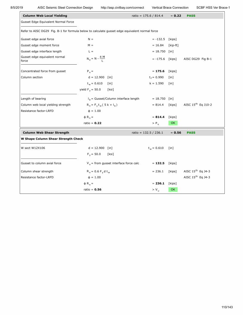
8/5/2019 AISC Seismic Steel Connection Design http://asp.civilbay.com/connect Vertical Brace Connection SCBF HSS Ver Brace-1
110/143
Column Web Local Yielding ratio = 175.6 / 814.4 = 0.22 PASS
Gusset Edge Equivalent Normal Force
Refer to AISC DG29 Fig. B-1 for formula below to calculate gusset edge equivalent normal force
Gusset edge axial force N = = -132.5 [kips]
Gusset edge moment force M = = 16.84 [kip-ft]
Gusset edge interface length L = = 18.750 [in]
Gusset edge equivalent normalforce
N = N - 4 ML = -175.6 [kips] AISC DG29 Fig B-1
Concentrated force from gusset P = = 175.6 [kips]
Column section d = 12.900 [in] t = 0.990 [in]
t = 0.610 [in] k = 1.590 [in]
yield F = 50.0 [ksi]
Length of bearing l = Gusset/Column interface length = 18.750 [in]
Column web local yielding strength R = F t ( 5 k + l ) = 814.4 [kips] AISC 15 Eq J10-2
Resistance factor-LRFD φ = 1.00
φ R = = 814.4 [kips]
ratio = 0.22 > P OK
Column Web Shear Strength ratio = 132.5 / 236.1 = 0.56 PASS
W Shape Column Shear Strength Check
W sect W12X106 d = 12.900 [in] t = 0.610 [in]
F = 50.0 [ksi]
Gusset to column axial force V = from gusset interface force calc = 132.5 [kips]
Column shear strength R = 0.6 F d t = 236.1 [kips] AISC 15 Eq J4-3
Resistance factor-LRFD φ = 1.00 AISC 15 Eq J4-3
φ R = = 236.1 [kips]
ratio = 0.56 > V OK
e
u
f
w
y
b
n y w bth
n
u
w
y
u
n y wth
th
n
u

8/5/2019 AISC Seismic Steel Connection Design http://asp.civilbay.com/connect Vertical Brace Connection SCBF HSS Ver Brace-1
111/143
Bot Brace - Gusset to Beam Direct Weld Connection Code=AISC 360-16 LRFD
Result Summary geometries & weld limitations = PASS limit states max ratio = 0.82 PASS
Brace Weld Limitation Checks - Gusset to Beam PASS
Min Fillet Weld Size
Thinner part joined thickness t = = 0.750 [in]
Min fillet weld size allowed w = = 0.250 [in] AISC 15 Table J2.4
Fillet weld size provided w = = 0.438 [in]
≥ w OK
Min Fillet Weld Length
Fillet weld size provided w = = 0.438 [in]
Min fillet weld length allowed L = 4 x w = 1.750 [in] AISC 15 J2.2b
Min fillet weld length L = = 27.500 [in]
≥ L OK
Seismic SCBF LC3 P =-559.7 kips (T) P =157.3 kips (C) ratio = 0.18 PASS
Gusset Plate - Shear Yielding ratio = 77.4 / 618.8 = 0.13 PASS
Plate Shear Yielding Check
Plate size width b = 27.500 [in] thickness t = 0.750 [in]
Plate yield strength F = 50.0 [ksi]
Plate gross area in shear A = b t = 20.625 [in ]
Shear force required V = = 77.4 [kips]
Plate shear yielding strength R = 0.6 F A = 618.8 [kips] AISC 15 Eq J4-3
Resistance factor-LRFD φ = 1.00 AISC 15 Eq J4-3
φ R = = 618.8 [kips]
ratio = 0.13 > V OK
Gusset Plate - Shear Rupture ratio = 77.4 / 603.3 = 0.13 PASS
Plate Shear Rupture Check
Plate size width b = 27.500 [in] thickness t = 0.750 [in]
Plate tensile strength F = 65.0 [ksi]
Plate net area in shear A = b t = 20.625 [in ]
Shear force in demand V = = 77.4 [kips]
Plate shear rupture strength R = 0.6 F A = 804.4 [kips] AISC 15 Eq J4-4
Resistance factor-LRFD φ = 0.75 AISC 15 Eq J4-4
φ R = = 603.3 [kips]
ratio = 0.13 > V OK
minth
min
minth
min
1 2
p p
y
gv p p2
u
n y gvth
th
n
u
p p
u
nv p p2
u
n u nvth
th
n
u

8/5/2019 AISC Seismic Steel Connection Design http://asp.civilbay.com/connect Vertical Brace Connection SCBF HSS Ver Brace-1
112/143
Gusset Plate - Axial Tensile Yield ratio = 64.8 / 928.1 = 0.07 PASS
Plate Tensile Yielding Check
Plate size width b = 27.500 [in] thickness t = 0.750 [in]
Plate yield strength F = 50.0 [ksi]
Plate gross area in shear A = b t = 20.625 [in ]
Tensile force required P = = 64.8 [kips]
Plate tensile yielding strength R = F A = 1031.3 [kips] AISC 15 Eq J4-1
Resistance factor-LRFD φ = 0.90 AISC 15 Eq J4-1
φ R = = 928.1 [kips]
ratio = 0.07 > P OK
Gusset Plate - Flexural Yield Interact ratio = = 0.02 PASS
Gusset plate width b = 27.500 [in] thick t = 0.750 [in]
yield F = 50.0 [ksi]
Shear plate - gross area A = b x t = 20.625 [in ]
Shear plate - plastic modulus Z = ( b x t ) / 4 = 141.80 [in ]
Flexural strength available M = φ F Z φ=0.90 = 531.74 [kip-ft]
Flexural strength required M = from gusset interface forces calc = 0.00 [kip-ft]
Axial strength available P = from axial tensile yield check = 928.1 [kips]
Axial strength required P = from gusset interface forces calc = 64.8 [kips]
Shear strength available V = from shear yielding check = 618.8 [kips]
Shear strength required V = from gusset interface forces calc = 77.4 [kips]
Flexural yield interaction ratio = ( V
V) + (
P
P +
M
M ) = 0.02 AISC 15 Eq 10-5
< 1.0 OK
Gusset Plate - Flexural Rupture Interact ratio = = 0.02 PASS
Gusset plate width b = 27.500 [in] thick t = 0.750 [in]
tensile F = 65.0 [ksi]
Net area of plate A = b x t = 20.625 [in ]
Plastic modulus of net section Z = ( b x t ) / 4 = 141.80 [in ]
Flexural strength available M = φ F Z φ=0.75 = 576.05 [kip-ft]
Flexural strength required M = from gusset interface forces calc = 0.00 [kip-ft]
Shear strength available V = from shear rupture check = 603.3 [kips]
Shear strength required V = from gusset interface forces calc = 77.4 [kips]
Flexural rupture interaction ratio = ( V
V) + (
M
M ) = 0.02 AISC 15 Eq 10-5
< 1.0 OK
p p
y
g p p2
u
n y gth
th
n
u
p p
y
g p p2
p p2p
3
c y p
r
c
r
c
r
r
c
2 r
c
r
c
2 th
p p
u
n p p2
net p2p
3
c u net
r
c
r
r
c
2 r
c
2 th

8/5/2019 AISC Seismic Steel Connection Design http://asp.civilbay.com/connect Vertical Brace Connection SCBF HSS Ver Brace-1
113/143
Gusset to Beam Weld Strength ratio = 2.81 / 15.59 = 0.18 PASS
Gusset to Beam Interface - Forces
shear H = 77.4 [kips] axial V = 64.8 [kips] in compression
moment M = 0.00 [kip-ft]
Gusset-beam fillet weld length L = = 27.500 [in]
Gusset to Beam Interface - Combined Weld Stress
Weld stress from axial force f = V / L = 0.000 [kip/in] in compression
Weld stress from shear force f = H / L = 2.815 [kip/in]
Weld stress from moment force f = M
L / 6 = 0.000 [kip/in]
Weld stress combined - max f = f = 2.815 [kip/in] AISC 15 Eq 8-11
Weld resultant load angle θ = weld only has shear component = 0.0 [°]
Fillet Weld Strength Calc
Fillet weld leg size w = ⁄ [in] load angle θ = 0.0 [°]
Electrode strength F = 70.0 [ksi] strength coeff C = 1.00 AISC 15 Table 8-3
Number of weld line n = 2 for double fillet
Load angle coefficient C = ( 1 + 0.5 sin θ ) = 1.00 AISC 15 Page 8-9
Fillet weld shear strength R = 0.6 (C x 70 ksi) 0.707 w n C = 25.982 [kip/in] AISC 15 Eq 8-1
Base metal - gusset plate thickness t = 0.750 [in] tensile F = 65.0 [ksi]
Base metal - gusset plate is in shear, shear rupture as per AISC 15 Eq J4-4 is checked AISC 15 J2.4
Base metal shear rupture R = 0.6 F t = 29.250 [kip/in] AISC 15 Eq J4-4
Double fillet linear shear strength R = min ( R , R ) = 25.982 [kip/in] AISC 15 Eq 9-2
Resistance factor-LRFD φ = 0.75 AISC 15 Eq 8-1
φ R = = 19.487 [kip/in]
When gusset plate is directly welded to beam or column, apply 1.25 ductility factorto allow adequate force redistribution in the weld group AISC 15 Page 13-11
Weld strength used for design afterapplying ductility factor
φ R = φ R x ( 1/1.25 ) = 15.589 [kip/in]
ratio = 0.18 > f OK
Beam Web Local Yielding ratio = 64.8 / 1022.9 = 0.06 PASS
Concentrated force from gusset P = = 64.8 [kips]
Beam section d = 24.700 [in] t = 1.090 [in]
t = 0.650 [in] k = 1.590 [in]
yield F = 50.0 [ksi]
Length of bearing l = Gusset/Beam interface length = 27.500 [in]
Gusset plate corner clip clip = from user input = 1.000 [in]
Distance from normal force appliedpoint to member end
l = 0.5 l + clip = 14.750 [in]
when l ≤ d , use AISC 15 Eq J10-3 AISC 15 Eq J10-3
Beam web local yielding strength R = F t ( 2.5 k + l ) = 1022.9 [kips] AISC 15 Eq J10-3
Resistance factor-LRFD φ = 1.00
φ R = = 1022.9 [kips]
ratio = 0.06 > P OK
b b
b
w
a b wb
v b wb
b 2
max vth
716
EXX 1th
21.5 th
n-w 1 2th
u
th th
n-b uth
n n-w n-bth
th
n
th
n n
max
u
f
w
y
b
N b
Nth th
n y w bth
n
u

8/5/2019 AISC Seismic Steel Connection Design http://asp.civilbay.com/connect Vertical Brace Connection SCBF HSS Ver Brace-1
114/143
Beam Web Local Crippling ratio = 64.8 / 1003.3 = 0.06 PASS
Concentrated force from gusset P = = 64.8 [kips]
Beam section d = 24.700 [in] t = 1.090 [in]
t = 0.650 [in] k = 1.590 [in]
yield F = 50.0 [ksi] E = 29000 [ksi]
Length of bearing l = Gusset/Beam interface length = 27.500 [in]
Gusset plate corner clip clip = from user input = 1.000 [in]
Distance from normal force appliedpoint to member end
l = 0.5 l + clip = 14.750 [in]
when l ≥ d/2 , use Eq J10-4 AISC 15 Eq J10-4
Beam web local crippling strength R = 0.8 t [1+3l
d(
t
t ) ] x = 1337.7 [kips] AISC 15 Eq J10-4
( E F tt
)
Resistance factor-LRFD φ = 0.75 AISC 15 J10.3
φR = = 1003.3 [kips]
ratio = 0.06 > P OK
Seismic SCBF LC4 P =134.7 kips (C) P =-615.9 kips (T) ratio = 0.82 PASS
Gusset Plate - Shear Yielding ratio = 303.0 / 618.8 = 0.49 PASS
Plate Shear Yielding Check
Plate size width b = 27.500 [in] thickness t = 0.750 [in]
Plate yield strength F = 50.0 [ksi]
Plate gross area in shear A = b t = 20.625 [in ]
Shear force required V = = 303.0 [kips]
Plate shear yielding strength R = 0.6 F A = 618.8 [kips] AISC 15 Eq J4-3
Resistance factor-LRFD φ = 1.00 AISC 15 Eq J4-3
φ R = = 618.8 [kips]
ratio = 0.49 > V OK
Gusset Plate - Shear Rupture ratio = 303.0 / 603.3 = 0.50 PASS
Plate Shear Rupture Check
Plate size width b = 27.500 [in] thickness t = 0.750 [in]
Plate tensile strength F = 65.0 [ksi]
Plate net area in shear A = b t = 20.625 [in ]
Shear force in demand V = = 303.0 [kips]
Plate shear rupture strength R = 0.6 F A = 804.4 [kips] AISC 15 Eq J4-4
Resistance factor-LRFD φ = 0.75 AISC 15 Eq J4-4
φ R = = 603.3 [kips]
ratio = 0.50 > V OK
u
f
w
y
b
N b
Nth
n2w
b w
f
1.5 th
y f
w
0.5
th
n
u
1 2
p p
y
gv p p2
u
n y gvth
th
n
u
p p
u
nv p p2
u
n u nvth
th
n
u

8/5/2019 AISC Seismic Steel Connection Design http://asp.civilbay.com/connect Vertical Brace Connection SCBF HSS Ver Brace-1
115/143
Gusset Plate - Axial Yield ratio = 253.7 / 928.1 = 0.27 PASS
Plate Tensile Yielding Check
Plate size width b = 27.500 [in] thickness t = 0.750 [in]
Plate yield strength F = 50.0 [ksi]
Plate gross area in shear A = b t = 20.625 [in ]
Tensile force required P = = 253.7 [kips]
Plate tensile yielding strength R = F A = 1031.3 [kips] AISC 15 Eq J4-1
Resistance factor-LRFD φ = 0.90 AISC 15 Eq J4-1
φ R = = 928.1 [kips]
ratio = 0.27 > P OK
Gusset Plate - Axial Tensile Rupture ratio = 253.7 / 1005.5 = 0.25 PASS
Plate Tensile Rupture Check
Plate size width b = 27.500 [in] thickness t = 0.750 [in]
Plate tensile strength F = 65.0 [ksi]
Plate net area in tension A = b t = 20.625 [in ]
Tensile force required P = = 253.7 [kips]
Plate tensile rupture strength R = F A = 1340.6 [kips] AISC 15 Eq J4-2
Resistance factor-LRFD φ = 0.75 AISC 15 Eq J4-2
φ R = = 1005.5 [kips] AISC 15 Eq J4-2
ratio = 0.25 > P OK
Gusset Plate - Flexural Yield Interact ratio = = 0.31 PASS
Gusset plate width b = 27.500 [in] thick t = 0.750 [in]
yield F = 50.0 [ksi]
Shear plate - gross area A = b x t = 20.625 [in ]
Shear plate - plastic modulus Z = ( b x t ) / 4 = 141.80 [in ]
Flexural strength available M = φ F Z φ=0.90 = 531.74 [kip-ft]
Flexural strength required M = from gusset interface forces calc = 0.00 [kip-ft]
Axial strength available P = from axial tensile yield check = 928.1 [kips]
Axial strength required P = from gusset interface forces calc = -253.7 [kips]
Shear strength available V = from shear yielding check = 618.8 [kips]
Shear strength required V = from gusset interface forces calc = 303.0 [kips]
Flexural yield interaction ratio = ( V
V) + (
P
P +
M
M ) = 0.31 AISC 15 Eq 10-5
< 1.0 OK
p p
y
g p p2
u
n y gth
th
n
u
p p
u
nt p p2
u
n u ntth
th
nth
u
p p
y
g p p2
p p2p
3
c y p
r
c
r
c
r
r
c
2 r
c
r
c
2 th

8/5/2019 AISC Seismic Steel Connection Design http://asp.civilbay.com/connect Vertical Brace Connection SCBF HSS Ver Brace-1
116/143
Gusset Plate - Flexural Rupture Interact ratio = = 0.32 PASS
Gusset plate width b = 27.500 [in] thick t = 0.750 [in]
tensile F = 65.0 [ksi]
Net area of plate A = b x t = 20.625 [in ]
Plastic modulus of net section Z = ( b x t ) / 4 = 141.80 [in ]
Flexural strength available M = φ F Z φ=0.75 = 576.05 [kip-ft]
Flexural strength required M = from gusset interface forces calc = 0.00 [kip-ft]
Axial strength available P = from axial tensile rupture check = 1005.5 [kips]
Axial strength required P = from gusset interface forces calc = -253.7 [kips]
Shear strength available V = from shear rupture check = 603.3 [kips]
Shear strength required V = from gusset interface forces calc = 303.0 [kips]
Flexural rupture interaction ratio = ( V
V) + (
P
P +
M
M ) = 0.32 AISC 15 Eq 10-5
< 1.0 OK
Gusset to Beam Weld Strength ratio = 14.37 / 17.55 = 0.82 PASS
Gusset to Beam Interface - Forces
shear H = 303.0 [kips] axial V = -253.7 [kips] in tension
moment M = 0.00 [kip-ft]
Gusset-beam fillet weld length L = = 27.500 [in]
Gusset to Beam Interface - Combined Weld Stress
Weld stress from axial force f = V / L = -9.225 [kip/in] in tension
Weld stress from shear force f = H / L = 11.018 [kip/in]
Weld stress from moment force f = M
L / 6 = 0.000 [kip/in]
Weld stress combined - max f = [ (f - f ) + f ] = 14.370 [kip/in] AISC 15 Eq 8-11
Weld resultant load angle θ = tan [( f - f ) / f ] = 39.9 [°]
Fillet Weld Strength Calc
Fillet weld leg size w = ⁄ [in] load angle θ = 39.9 [°]
Electrode strength F = 70.0 [ksi] strength coeff C = 1.00 AISC 15 Table 8-3
Number of weld line n = 2 for double fillet
Load angle coefficient C = ( 1 + 0.5 sin θ ) = 1.26 AISC 15 Page 8-9
Fillet weld shear strength R = 0.6 (C x 70 ksi) 0.707 w n C = 32.665 [kip/in] AISC 15 Eq 8-1
Base metal - gusset plate thickness t = 0.750 [in] tensile F = 65.0 [ksi]
Base metal - gusset plate is in shear, shear rupture as per AISC 15 Eq J4-4 is checked AISC 15 J2.4
Base metal shear rupture R = 0.6 F t = 29.250 [kip/in] AISC 15 Eq J4-4
Double fillet linear shear strength R = min ( R , R ) = 29.250 [kip/in] AISC 15 Eq 9-2
Resistance factor-LRFD φ = 0.75 AISC 15 Eq 8-1
φ R = = 21.938 [kip/in]
When gusset plate is directly welded to beam or column, apply 1.25 ductility factorto allow adequate force redistribution in the weld group AISC 15 Page 13-11
Weld strength used for design afterapplying ductility factor
φ R = φ R x ( 1/1.25 ) = 17.550 [kip/in]
ratio = 0.82 > f OK
p p
u
n p p2
net p2p
3
c u net
r
c
r
c
r
r
c
2 r
c
r
c
2 th
b b
b
w
a b wb
v b wb
b 2
max a b2 2
v0.5 th
-1b a v
716
EXX 1th
21.5 th
n-w 1 2th
u
th th
n-b uth
n n-w n-bth
th
n
th
n n
max

8/5/2019 AISC Seismic Steel Connection Design http://asp.civilbay.com/connect Vertical Brace Connection SCBF HSS Ver Brace-1
117/143
Beam Web Local Yielding ratio = 253.7 / 1022.9 = 0.25 PASS
Concentrated force from gusset P = = 253.7 [kips]
Beam section d = 24.700 [in] t = 1.090 [in]
t = 0.650 [in] k = 1.590 [in]
yield F = 50.0 [ksi]
Length of bearing l = Gusset/Beam interface length = 27.500 [in]
Gusset plate corner clip clip = from user input = 1.000 [in]
Distance from normal force appliedpoint to member end
l = 0.5 l + clip = 14.750 [in]
when l ≤ d , use AISC 15 Eq J10-3 AISC 15 Eq J10-3
Beam web local yielding strength R = F t ( 2.5 k + l ) = 1022.9 [kips] AISC 15 Eq J10-3
Resistance factor-LRFD φ = 1.00
φ R = = 1022.9 [kips]
ratio = 0.25 > P OK
u
f
w
y
b
N b
Nth th
n y w bth
n
u
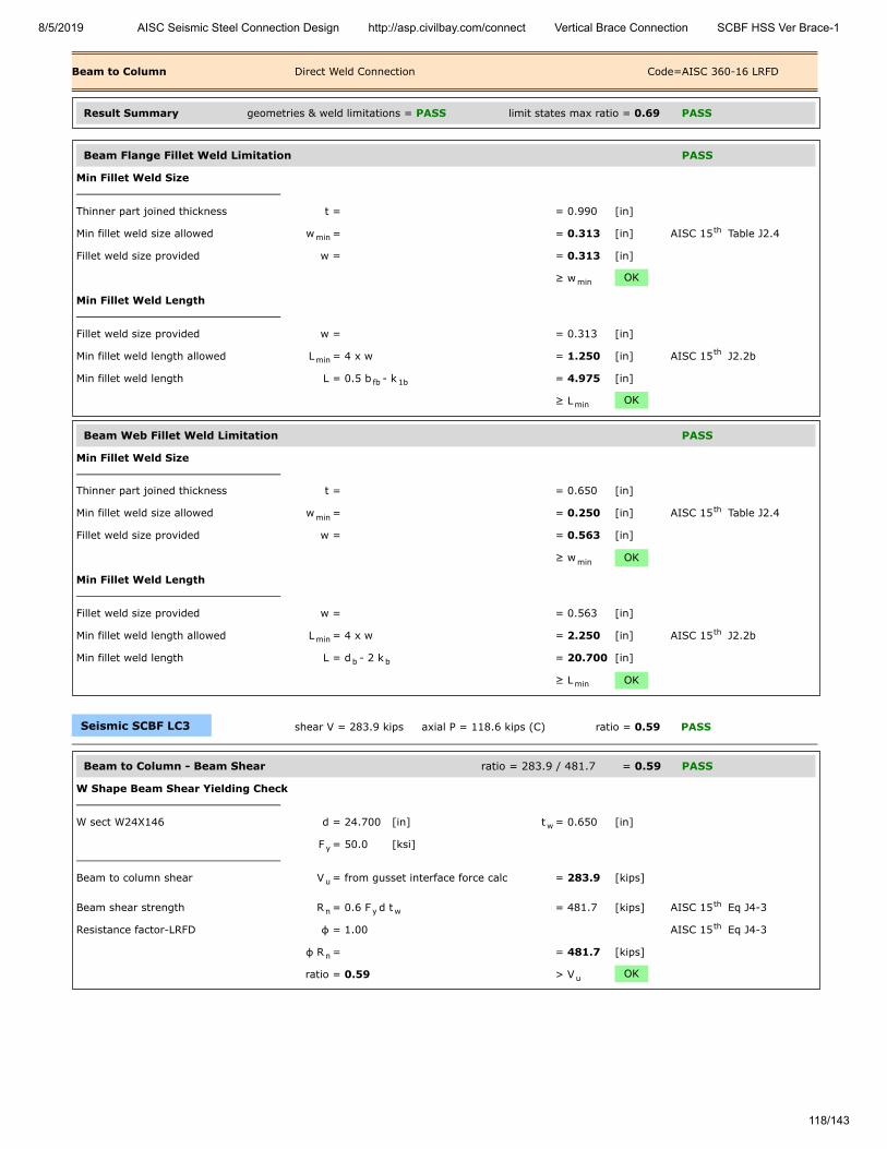
8/5/2019 AISC Seismic Steel Connection Design http://asp.civilbay.com/connect Vertical Brace Connection SCBF HSS Ver Brace-1
118/143
Beam to Column Direct Weld Connection Code=AISC 360-16 LRFD
Result Summary geometries & weld limitations = PASS limit states max ratio = 0.69 PASS
Beam Flange Fillet Weld Limitation PASS
Min Fillet Weld Size
Thinner part joined thickness t = = 0.990 [in]
Min fillet weld size allowed w = = 0.313 [in] AISC 15 Table J2.4
Fillet weld size provided w = = 0.313 [in]
≥ w OK
Min Fillet Weld Length
Fillet weld size provided w = = 0.313 [in]
Min fillet weld length allowed L = 4 x w = 1.250 [in] AISC 15 J2.2b
Min fillet weld length L = 0.5 b - k = 4.975 [in]
≥ L OK
Beam Web Fillet Weld Limitation PASS
Min Fillet Weld Size
Thinner part joined thickness t = = 0.650 [in]
Min fillet weld size allowed w = = 0.250 [in] AISC 15 Table J2.4
Fillet weld size provided w = = 0.563 [in]
≥ w OK
Min Fillet Weld Length
Fillet weld size provided w = = 0.563 [in]
Min fillet weld length allowed L = 4 x w = 2.250 [in] AISC 15 J2.2b
Min fillet weld length L = d - 2 k = 20.700 [in]
≥ L OK
Seismic SCBF LC3 shear V = 283.9 kips axial P = 118.6 kips (C) ratio = 0.59 PASS
Beam to Column - Beam Shear ratio = 283.9 / 481.7 = 0.59 PASS
W Shape Beam Shear Yielding Check
W sect W24X146 d = 24.700 [in] t = 0.650 [in]
F = 50.0 [ksi]
Beam to column shear V = from gusset interface force calc = 283.9 [kips]
Beam shear strength R = 0.6 F d t = 481.7 [kips] AISC 15 Eq J4-3
Resistance factor-LRFD φ = 1.00 AISC 15 Eq J4-3
φ R = = 481.7 [kips]
ratio = 0.59 > V OK
minth
min
minth
fb 1b
min
minth
min
minth
b b
min
w
y
u
n y wth
th
n
u

8/5/2019 AISC Seismic Steel Connection Design http://asp.civilbay.com/connect Vertical Brace Connection SCBF HSS Ver Brace-1
119/143
Beam to Column - Beam Stub Compressive Strength ratio = 118.6 / 1935.0 = 0.06 PASS
W Shape Compression Check
W sect W24X146 A = 43.000 [in ] r = 3.022 [in]
F = 50.0 [ksi]
W sect effective length factor K = = 1.00
W sect unbraced length L = = 30.000 [in]
W sect slenderness KL/r = 1.00 x L / r = 9.93
Compression force on W sect P = = 118.6 [kips]
when KL
r ≤ 25 AISC 15 J4.4 (a)
W sect compression provided R = F x A = 2150.0 [kips] AISC 15 Eq J4-6
Resistance factor-LRFD φ = 0.90 AISC 15 J4.4 (a)
φ R = = 1935.0 [kips]
ratio = 0.06 > P OK
Beam W Shape Axial Force Distribution
W Shape Beam Axial Force Distribution
W sect W24X146 d = 24.700 [in] b = 12.900 [in]
t = 1.090 [in] t = 0.650 [in]
A = 43.000 [in ]
W shape one side flange area A = b t = 14.061 [in ]
W shape web area A = A- 2 A = 14.878 [in ]
W shape axial force P = = 118.6 [kips]
Axial force on flange P = AA
P = 38.8 [kips]
Axial force on web P = AA
P = 41.0 [kips]
Beam to Column - W Shape Flange Weld ratio = NA = 0.00 PASS
Beam flange tensile force P = from beam axial force distribution calc = 38.8 [kips]
Beam flange force is in compression, the flange weld check is not needed
2y
y
y
u
th
n yth
th
n
u
f
f w
2
f f f2
w f2
ff
ww
u

8/5/2019 AISC Seismic Steel Connection Design http://asp.civilbay.com/connect Vertical Brace Connection SCBF HSS Ver Brace-1
120/143
Beam to Column - W Shape Web Weld ratio = 13.71 / 25.05 = 0.55 PASS
Beam section W24X146 d = 24.700 [in] k = 2.000 [in]
Fillet weld length on beam web L = d - 2 k = 20.700 [in]
Weld Group Forces
Weld group forces shear V = 283.9 [kips] axial P = 41.0 [kips] in compression
Beam web fillet weld size w = = 0.563 [in]
Combined Weld Stress
Weld stress from axial force f = P / L = 0.000 [kip/in] in compression
Weld stress from shear force f = V / L = 13.715 [kip/in]
Weld stress combined - max f = f = 13.715 [kip/in] AISC 15 Eq 8-11
Weld stress load angle θ = = 0.0 [°]
Fillet Weld Strength Calc
Fillet weld leg size w = ⁄ [in] load angle θ = 0.0 [°]
Electrode strength F = 70.0 [ksi] strength coeff C = 1.00 AISC 15 Table 8-3
Number of weld line n = 2 for double fillet
Load angle coefficient C = ( 1 + 0.5 sin θ ) = 1.00 AISC 15 Page 8-9
Fillet weld shear strength R = 0.6 (C x 70 ksi) 0.707 w n C = 33.406 [kip/in] AISC 15 Eq 8-1
Base metal - beam web thickness t = 0.650 [in] tensile F = 65.0 [ksi]
Base metal - beam web is in tension, tensile rupture as per AISC 15 Eq J4-2 is checked AISC 15 J2.4
Base metal tensile rupture R = F t = 42.250 [kip/in] AISC 15 Eq J4-2
Double fillet linear shear strength R = min ( R , R ) = 33.406 [kip/in] AISC 15 Eq 9-2
Resistance factor-LRFD φ = 0.75 AISC 15 Eq 8-1
φ R = = 25.054 [kip/in]
ratio = 0.55 > f OK
Column Web Local Yielding - Beam Flange ratio = 38.8 / 275.7 = 0.14 PASS
Column Web Local Yielding at Beam Flange Location
Column sect W12X106 k = 1.590 [in] t = 0.610 [in]
F = 50.0 [ksi]
Beam section W24X146 t = 1.090 [in]
Beam flange force P = from beam axial force distribution calc = 38.8 [kips]
Column web local yielding strength R = F t (5 k + t ) = 275.7 [kips] AISC 15 Eq 4-2
Resistance factor-LRFD φ = 1.00 AISC 15 Eq 4-2
φ R = = 275.7 [kips]
ratio = 0.14 > P OK
b b
b b
a
v
max vth
916
EXX 1th
21.5 th
n-w 1 2th
u
th th
n-b uth
n n-w n-bth
th
n
max
c wc
yc
fb
u
n yc wc c fbth
th
n
u
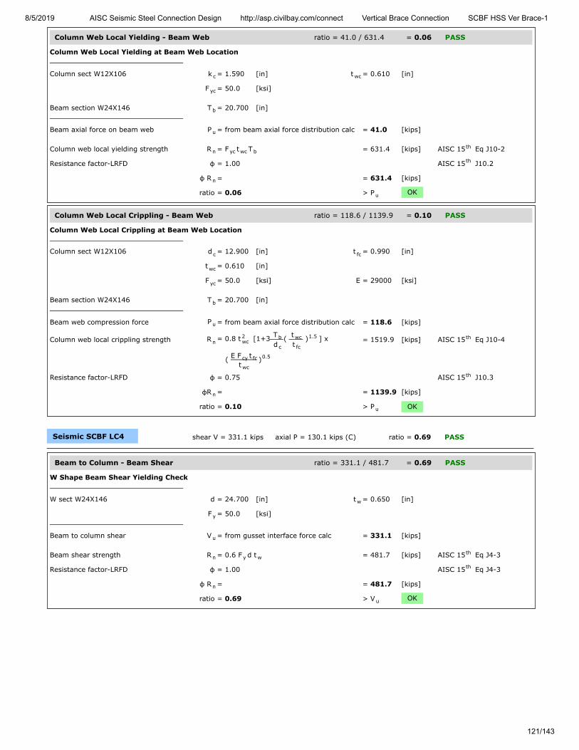
8/5/2019 AISC Seismic Steel Connection Design http://asp.civilbay.com/connect Vertical Brace Connection SCBF HSS Ver Brace-1
121/143
Column Web Local Yielding - Beam Web ratio = 41.0 / 631.4 = 0.06 PASS
Column Web Local Yielding at Beam Web Location
Column sect W12X106 k = 1.590 [in] t = 0.610 [in]
F = 50.0 [ksi]
Beam section W24X146 T = 20.700 [in]
Beam axial force on beam web P = from beam axial force distribution calc = 41.0 [kips]
Column web local yielding strength R = F t T = 631.4 [kips] AISC 15 Eq J10-2
Resistance factor-LRFD φ = 1.00 AISC 15 J10.2
φ R = = 631.4 [kips]
ratio = 0.06 > P OK
Column Web Local Crippling - Beam Web ratio = 118.6 / 1139.9 = 0.10 PASS
Column Web Local Crippling at Beam Web Location
Column sect W12X106 d = 12.900 [in] t = 0.990 [in]
t = 0.610 [in]
F = 50.0 [ksi] E = 29000 [ksi]
Beam section W24X146 T = 20.700 [in]
Beam web compression force P = from beam axial force distribution calc = 118.6 [kips]
Column web local crippling strength R = 0.8 t [1+3 Td
( tt
) ] x = 1519.9 [kips] AISC 15 Eq J10-4
( E F tt
)
Resistance factor-LRFD φ = 0.75 AISC 15 J10.3
φR = = 1139.9 [kips]
ratio = 0.10 > P OK
Seismic SCBF LC4 shear V = 331.1 kips axial P = 130.1 kips (C) ratio = 0.69 PASS
Beam to Column - Beam Shear ratio = 331.1 / 481.7 = 0.69 PASS
W Shape Beam Shear Yielding Check
W sect W24X146 d = 24.700 [in] t = 0.650 [in]
F = 50.0 [ksi]
Beam to column shear V = from gusset interface force calc = 331.1 [kips]
Beam shear strength R = 0.6 F d t = 481.7 [kips] AISC 15 Eq J4-3
Resistance factor-LRFD φ = 1.00 AISC 15 Eq J4-3
φ R = = 481.7 [kips]
ratio = 0.69 > V OK
c wc
yc
b
u
n yc wc bth
th
n
u
c fc
wc
yc
b
u
n2wc
b
c
wc
fc
1.5 th
cy fc
wc
0.5
th
n
u
w
y
u
n y wth
th
n
u

8/5/2019 AISC Seismic Steel Connection Design http://asp.civilbay.com/connect Vertical Brace Connection SCBF HSS Ver Brace-1
122/143
Beam to Column - Beam Stub Compressive Strength ratio = 130.1 / 1935.0 = 0.07 PASS
W Shape Compression Check
W sect W24X146 A = 43.000 [in ] r = 3.022 [in]
F = 50.0 [ksi]
W sect effective length factor K = = 1.00
W sect unbraced length L = = 30.000 [in]
W sect slenderness KL/r = 1.00 x L / r = 9.93
Compression force on W sect P = = 130.1 [kips]
when KL
r ≤ 25 AISC 15 J4.4 (a)
W sect compression provided R = F x A = 2150.0 [kips] AISC 15 Eq J4-6
Resistance factor-LRFD φ = 0.90 AISC 15 J4.4 (a)
φ R = = 1935.0 [kips]
ratio = 0.07 > P OK
Beam W Shape Axial Force Distribution
W Shape Beam Axial Force Distribution
W sect W24X146 d = 24.700 [in] b = 12.900 [in]
t = 1.090 [in] t = 0.650 [in]
A = 43.000 [in ]
W shape one side flange area A = b t = 14.061 [in ]
W shape web area A = A- 2 A = 14.878 [in ]
W shape axial force P = = 130.1 [kips]
Axial force on flange P = AA
P = 42.5 [kips]
Axial force on web P = AA
P = 45.0 [kips]
Beam to Column - W Shape Flange Weld ratio = NA = 0.00 PASS
Beam flange tensile force P = from beam axial force distribution calc = 42.5 [kips]
Beam flange force is in compression, the flange weld check is not needed
2y
y
y
u
th
n yth
th
n
u
f
f w
2
f f f2
w f2
ff
ww
u
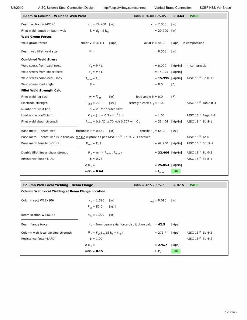
8/5/2019 AISC Seismic Steel Connection Design http://asp.civilbay.com/connect Vertical Brace Connection SCBF HSS Ver Brace-1
123/143
Beam to Column - W Shape Web Weld ratio = 16.00 / 25.05 = 0.64 PASS
Beam section W24X146 d = 24.700 [in] k = 2.000 [in]
Fillet weld length on beam web L = d - 2 k = 20.700 [in]
Weld Group Forces
Weld group forces shear V = 331.1 [kips] axial P = 45.0 [kips] in compression
Beam web fillet weld size w = = 0.563 [in]
Combined Weld Stress
Weld stress from axial force f = P / L = 0.000 [kip/in] in compression
Weld stress from shear force f = V / L = 15.995 [kip/in]
Weld stress combined - max f = f = 15.995 [kip/in] AISC 15 Eq 8-11
Weld stress load angle θ = = 0.0 [°]
Fillet Weld Strength Calc
Fillet weld leg size w = ⁄ [in] load angle θ = 0.0 [°]
Electrode strength F = 70.0 [ksi] strength coeff C = 1.00 AISC 15 Table 8-3
Number of weld line n = 2 for double fillet
Load angle coefficient C = ( 1 + 0.5 sin θ ) = 1.00 AISC 15 Page 8-9
Fillet weld shear strength R = 0.6 (C x 70 ksi) 0.707 w n C = 33.406 [kip/in] AISC 15 Eq 8-1
Base metal - beam web thickness t = 0.650 [in] tensile F = 65.0 [ksi]
Base metal - beam web is in tension, tensile rupture as per AISC 15 Eq J4-2 is checked AISC 15 J2.4
Base metal tensile rupture R = F t = 42.250 [kip/in] AISC 15 Eq J4-2
Double fillet linear shear strength R = min ( R , R ) = 33.406 [kip/in] AISC 15 Eq 9-2
Resistance factor-LRFD φ = 0.75 AISC 15 Eq 8-1
φ R = = 25.054 [kip/in]
ratio = 0.64 > f OK
Column Web Local Yielding - Beam Flange ratio = 42.5 / 275.7 = 0.15 PASS
Column Web Local Yielding at Beam Flange Location
Column sect W12X106 k = 1.590 [in] t = 0.610 [in]
F = 50.0 [ksi]
Beam section W24X146 t = 1.090 [in]
Beam flange force P = from beam axial force distribution calc = 42.5 [kips]
Column web local yielding strength R = F t (5 k + t ) = 275.7 [kips] AISC 15 Eq 4-2
Resistance factor-LRFD φ = 1.00 AISC 15 Eq 4-2
φ R = = 275.7 [kips]
ratio = 0.15 > P OK
b b
b b
a
v
max vth
916
EXX 1th
21.5 th
n-w 1 2th
u
th th
n-b uth
n n-w n-bth
th
n
max
c wc
yc
fb
u
n yc wc c fbth
th
n
u

8/5/2019 AISC Seismic Steel Connection Design http://asp.civilbay.com/connect Vertical Brace Connection SCBF HSS Ver Brace-1
124/143
Column Web Local Yielding - Beam Web ratio = 45.0 / 631.4 = 0.07 PASS
Column Web Local Yielding at Beam Web Location
Column sect W12X106 k = 1.590 [in] t = 0.610 [in]
F = 50.0 [ksi]
Beam section W24X146 T = 20.700 [in]
Beam axial force on beam web P = from beam axial force distribution calc = 45.0 [kips]
Column web local yielding strength R = F t T = 631.4 [kips] AISC 15 Eq J10-2
Resistance factor-LRFD φ = 1.00 AISC 15 J10.2
φ R = = 631.4 [kips]
ratio = 0.07 > P OK
Column Web Local Crippling - Beam Web ratio = 130.1 / 1139.9 = 0.11 PASS
Column Web Local Crippling at Beam Web Location
Column sect W12X106 d = 12.900 [in] t = 0.990 [in]
t = 0.610 [in]
F = 50.0 [ksi] E = 29000 [ksi]
Beam section W24X146 T = 20.700 [in]
Beam web compression force P = from beam axial force distribution calc = 130.1 [kips]
Column web local crippling strength R = 0.8 t [1+3 Td
( tt
) ] x = 1519.9 [kips] AISC 15 Eq J10-4
( E F tt
)
Resistance factor-LRFD φ = 0.75 AISC 15 J10.3
φR = = 1139.9 [kips]
ratio = 0.11 > P OK
Beam Splice Calculation Brace Seismic System = SCBF Code=AISC 360-16 LRFD
Result Summary geometries & weld limitations = PASS limit states max ratio = 0.61 PASS
Min Clearance Gap Between Beam Stub & Beam PASS
Refer to AISC Seismic Design Manual 2nd Ed Page 5-235, in order to prevent binding at a 0.025 rad storey drift,the clearance between beam stub and beam at the splice must be at least (0.5 beam depth x 0.025 rad)
Beam sect W24X146 depth d = = 24.700 [in]
Min required gap between beamstub and beam
c = 0.5 d x 0.025 rad = 0.309 [in]
Actual gap between beam stub andbeam
c = from user input = 1.000 [in]
≥ c OK
c wc
yc
b
u
n yc wc bth
th
n
u
c fc
wc
yc
b
u
n2wc
b
c
wc
fc
1.5 th
cy fc
wc
0.5
th
n
u
min
min

8/5/2019 AISC Seismic Steel Connection Design http://asp.civilbay.com/connect Vertical Brace Connection SCBF HSS Ver Brace-1
125/143
Splice Plate Thickness Limit for Ductility PASS
Bolt grade grade = A325-X
Nominal tensile/shear stress F = 90.0 [ksi] F = 68.0 [ksi] AISC 15 Table J3.2
Bolt diameter & area d = 0.875 [in] Area A = 0.601 [in ]
Bolt group row n = 6 col n = 2
row s = 3.000 [in] col s = 3.000 [in]
Bolt group coefficient C' C' = from AISC 15 Table 7-6 ~ 7-13 = 54.2
Splice plate thickness & depth t = 0.375 [in] d = 19.000 [in]
F = 50.0 [ksi]
Bolt group flexural strength M = F
0.9 ( A C') = 205.08 [kip-ft] AISC 15 Eq 10-4
Max allowed splice plate thickness t = 6 M
F d = 0.818 [in] AISC 15 Eq 10-3
Splice plate thickness provided 2t = t x 2 sides = 0.750 [in]
≤ t OK
Seismic SCBF LC3 shear V = 19.9 kips axial P = 312.1 kips (C) ratio = 0.61 PASS
Beam Web - Outer Side Bolt Group Eccentricity - Shear Only
Shear V - from user input, beam end shear reaction caused by gravity load onlye - hor distance from column face to the beam splice outer side bolt group CG point
Bolt group forces shear V = 19.9 [kips] axial P = 0.0 [kips]
Resultant force to ver Y axis angle θ = tan (P / V) = 0.00 [°]
Bolt group row and column bolt row n = 6 bolt col n = 2
Bolt row/column spacing bolt row s = 3.000 [in] bolt col s = 3.000 [in]
Shear force to bolt group CG ecc e = = 34.500 [in]
Shear force to ver Y axis angle θ = = 0.00 [°]
Bolt group coefficient C C = from AISC 15 Table 7-6 ~ 7-13 = 1.552
Bolt group eccentricity coefficient C = C / ( n x n ) = 0.129
Beam Web - Outer Side Bolt Group - Bolt Shear ratio = 19.9 / 94.9 = 0.21 PASS
Bolt group forces shear V = 19.9 [kips] axial P = 0.0 [kips]
Bolt group resultant force R = ( V + P ) = 19.9 [kips]
Bolt shear stress bolt grade = A325-X F = 68.0 [ksi] AISC 15 Table J3.2
bolt dia d = 0.875 [in] bolt area A = 0.601 [in ]
Number of bolt carried shear n = 12.0 shear plane m = 2
Bolt group eccentricity coefficient C = from 'Bolt Group Eccentricity' calc = 0.129
Required shear strength V = = 19.9 [kips]
Bolt shear strength R = F A n m C = 126.6 [kips] AISC 15 Eq J3-1
Bolt resistance factor-LRFD φ = 0.75 AISC 15 Eq J3-1
φ R = = 94.9 [kips]
ratio = 0.21 > V OK
t vth
b b2
v h
v h
th
y
maxv
bth
maxmax
y2
th
max
x
-1
r c
r c
x
th
ec r c
2 2 0.5
nvth
b b2
s
ec
u
n nv b s ecth
th
n
u
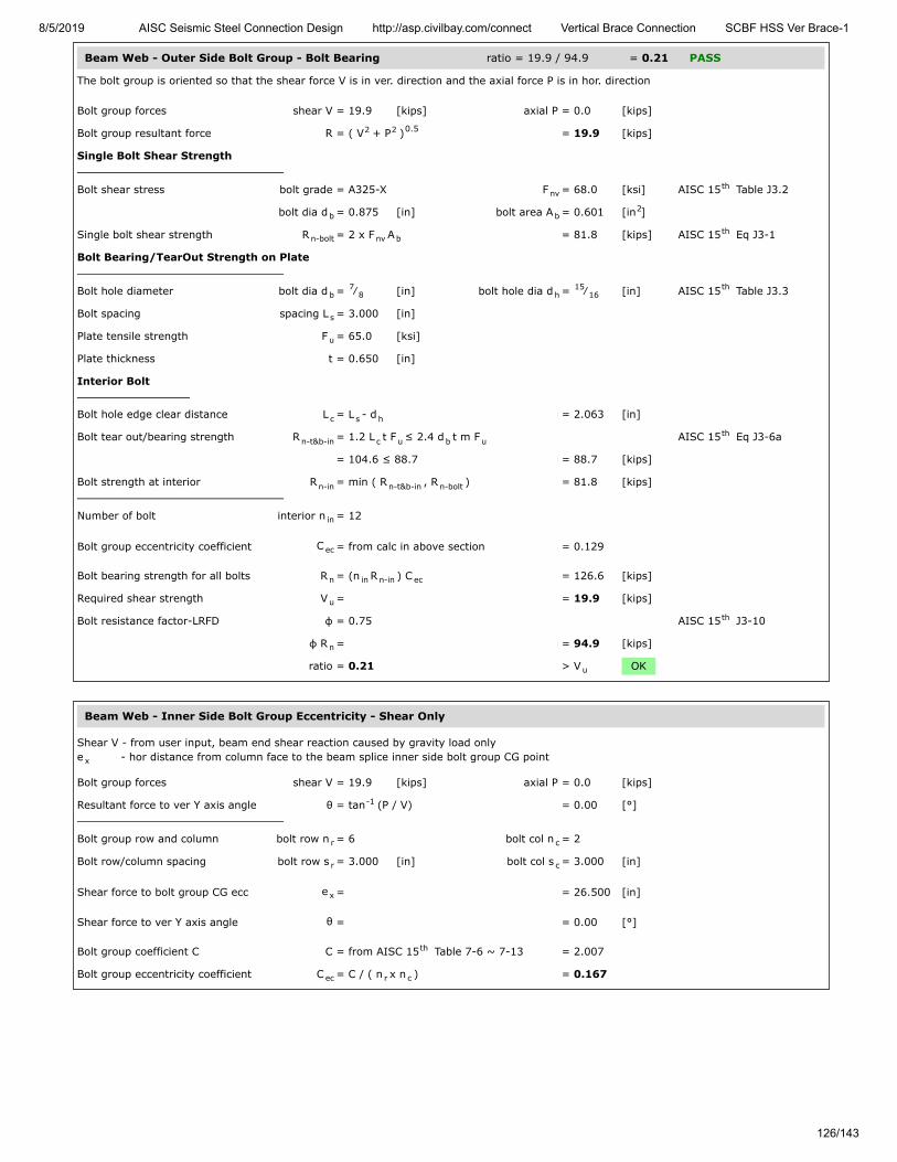
8/5/2019 AISC Seismic Steel Connection Design http://asp.civilbay.com/connect Vertical Brace Connection SCBF HSS Ver Brace-1
126/143
Beam Web - Outer Side Bolt Group - Bolt Bearing ratio = 19.9 / 94.9 = 0.21 PASS
The bolt group is oriented so that the shear force V is in ver. direction and the axial force P is in hor. direction
Bolt group forces shear V = 19.9 [kips] axial P = 0.0 [kips]
Bolt group resultant force R = ( V + P ) = 19.9 [kips]
Single Bolt Shear Strength
Bolt shear stress bolt grade = A325-X F = 68.0 [ksi] AISC 15 Table J3.2
bolt dia d = 0.875 [in] bolt area A = 0.601 [in ]
Single bolt shear strength R = 2 x F A = 81.8 [kips] AISC 15 Eq J3-1
Bolt Bearing/TearOut Strength on Plate
Bolt hole diameter bolt dia d = ⁄ [in] bolt hole dia d = ⁄ [in] AISC 15 Table J3.3
Bolt spacing spacing L = 3.000 [in]
Plate tensile strength F = 65.0 [ksi]
Plate thickness t = 0.650 [in]
Interior Bolt
Bolt hole edge clear distance L = L - d = 2.063 [in]
Bolt tear out/bearing strength R = 1.2 L t F ≤ 2.4 d t m F AISC 15 Eq J3-6a
= 104.6 ≤ 88.7 = 88.7 [kips]
Bolt strength at interior R = min ( R , R ) = 81.8 [kips]
Number of bolt interior n = 12
Bolt group eccentricity coefficient C = from calc in above section = 0.129
Bolt bearing strength for all bolts R = (n R ) C = 126.6 [kips]
Required shear strength V = = 19.9 [kips]
Bolt resistance factor-LRFD φ = 0.75 AISC 15 J3-10
φ R = = 94.9 [kips]
ratio = 0.21 > V OK
Beam Web - Inner Side Bolt Group Eccentricity - Shear Only
Shear V - from user input, beam end shear reaction caused by gravity load onlye - hor distance from column face to the beam splice inner side bolt group CG point
Bolt group forces shear V = 19.9 [kips] axial P = 0.0 [kips]
Resultant force to ver Y axis angle θ = tan (P / V) = 0.00 [°]
Bolt group row and column bolt row n = 6 bolt col n = 2
Bolt row/column spacing bolt row s = 3.000 [in] bolt col s = 3.000 [in]
Shear force to bolt group CG ecc e = = 26.500 [in]
Shear force to ver Y axis angle θ = = 0.00 [°]
Bolt group coefficient C C = from AISC 15 Table 7-6 ~ 7-13 = 2.007
Bolt group eccentricity coefficient C = C / ( n x n ) = 0.167
2 2 0.5
nvth
b b2
n-bolt nv bth
b7
8 h15
16th
s
u
c s h
n-t&b-in c u b uth
n-in n-t&b-in n-bolt
in
ec
n in n-in ec
u
th
n
u
x
-1
r c
r c
x
th
ec r c
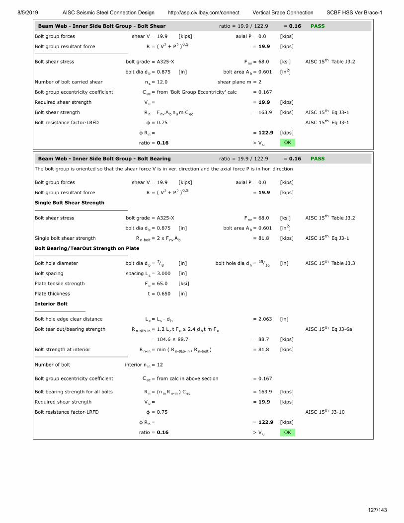
8/5/2019 AISC Seismic Steel Connection Design http://asp.civilbay.com/connect Vertical Brace Connection SCBF HSS Ver Brace-1
127/143
Beam Web - Inner Side Bolt Group - Bolt Shear ratio = 19.9 / 122.9 = 0.16 PASS
Bolt group forces shear V = 19.9 [kips] axial P = 0.0 [kips]
Bolt group resultant force R = ( V + P ) = 19.9 [kips]
Bolt shear stress bolt grade = A325-X F = 68.0 [ksi] AISC 15 Table J3.2
bolt dia d = 0.875 [in] bolt area A = 0.601 [in ]
Number of bolt carried shear n = 12.0 shear plane m = 2
Bolt group eccentricity coefficient C = from 'Bolt Group Eccentricity' calc = 0.167
Required shear strength V = = 19.9 [kips]
Bolt shear strength R = F A n m C = 163.9 [kips] AISC 15 Eq J3-1
Bolt resistance factor-LRFD φ = 0.75 AISC 15 Eq J3-1
φ R = = 122.9 [kips]
ratio = 0.16 > V OK
Beam Web - Inner Side Bolt Group - Bolt Bearing ratio = 19.9 / 122.9 = 0.16 PASS
The bolt group is oriented so that the shear force V is in ver. direction and the axial force P is in hor. direction
Bolt group forces shear V = 19.9 [kips] axial P = 0.0 [kips]
Bolt group resultant force R = ( V + P ) = 19.9 [kips]
Single Bolt Shear Strength
Bolt shear stress bolt grade = A325-X F = 68.0 [ksi] AISC 15 Table J3.2
bolt dia d = 0.875 [in] bolt area A = 0.601 [in ]
Single bolt shear strength R = 2 x F A = 81.8 [kips] AISC 15 Eq J3-1
Bolt Bearing/TearOut Strength on Plate
Bolt hole diameter bolt dia d = ⁄ [in] bolt hole dia d = ⁄ [in] AISC 15 Table J3.3
Bolt spacing spacing L = 3.000 [in]
Plate tensile strength F = 65.0 [ksi]
Plate thickness t = 0.650 [in]
Interior Bolt
Bolt hole edge clear distance L = L - d = 2.063 [in]
Bolt tear out/bearing strength R = 1.2 L t F ≤ 2.4 d t m F AISC 15 Eq J3-6a
= 104.6 ≤ 88.7 = 88.7 [kips]
Bolt strength at interior R = min ( R , R ) = 81.8 [kips]
Number of bolt interior n = 12
Bolt group eccentricity coefficient C = from calc in above section = 0.167
Bolt bearing strength for all bolts R = (n R ) C = 163.9 [kips]
Required shear strength V = = 19.9 [kips]
Bolt resistance factor-LRFD φ = 0.75 AISC 15 J3-10
φ R = = 122.9 [kips]
ratio = 0.16 > V OK
2 2 0.5
nvth
b b2
s
ec
u
n nv b s ecth
th
n
u
2 2 0.5
nvth
b b2
n-bolt nv bth
b7
8 h15
16th
s
u
c s h
n-t&b-in c u b uth
n-in n-t&b-in n-bolt
in
ec
n in n-in ec
u
th
n
u

8/5/2019 AISC Seismic Steel Connection Design http://asp.civilbay.com/connect Vertical Brace Connection SCBF HSS Ver Brace-1
128/143
Beam Web - Inner Side Bolt Group Eccentricity - Shear + Axial
Shear V - from user input, beam end shear reaction caused by gravity load onlyAxial P - from gusset interface forces calc , beam member axial load Pe - hor distance from the gusset-beam weld line CG point to the beam splice inner side bolt group CG point
Bolt group forces shear V = 19.9 [kips] axial P = 312.1 [kips]
Bolt group resultant force R = ( V + P ) = 312.7 [kips]
Resultant force to ver Y axis angle θ = tan (P / V) = 86.35 [°]
Bolt group row and column bolt row n = 6 bolt col n = 2
Bolt row/column spacing bolt row s = 3.000 [in] bolt col s = 3.000 [in]
Shear force to bolt group CG ecc e = = 12.125 [in]
Shear force to ver Y axis angle θ = = 86.35 [°]
Bolt group coefficient C C = from AISC 15 Table 7-6 ~ 7-13 = 10.595
Bolt group eccentricity coefficient C = C / ( n x n ) = 0.883
Beam Web - Inner Side Bolt Group - Bolt Shear ratio = 312.7 / 649.9 = 0.48 PASS
Bolt group forces shear V = 19.9 [kips] axial P = 312.1 [kips]
Bolt group resultant force R = ( V + P ) = 312.7 [kips]
Bolt shear stress bolt grade = A325-X F = 68.0 [ksi] AISC 15 Table J3.2
bolt dia d = 0.875 [in] bolt area A = 0.601 [in ]
Number of bolt carried shear n = 12.0 shear plane m = 2
Bolt group eccentricity coefficient C = from 'Bolt Group Eccentricity' calc = 0.883
Required shear strength V = = 312.7 [kips]
Bolt shear strength R = F A n m C = 866.5 [kips] AISC 15 Eq J3-1
Bolt resistance factor-LRFD φ = 0.75 AISC 15 Eq J3-1
φ R = = 649.9 [kips]
ratio = 0.48 > V OK
bm
x
2 2 0.5
-1
r c
r c
x
th
ec r c
2 2 0.5
nvth
b b2
s
ec
u
n nv b s ecth
th
n
u
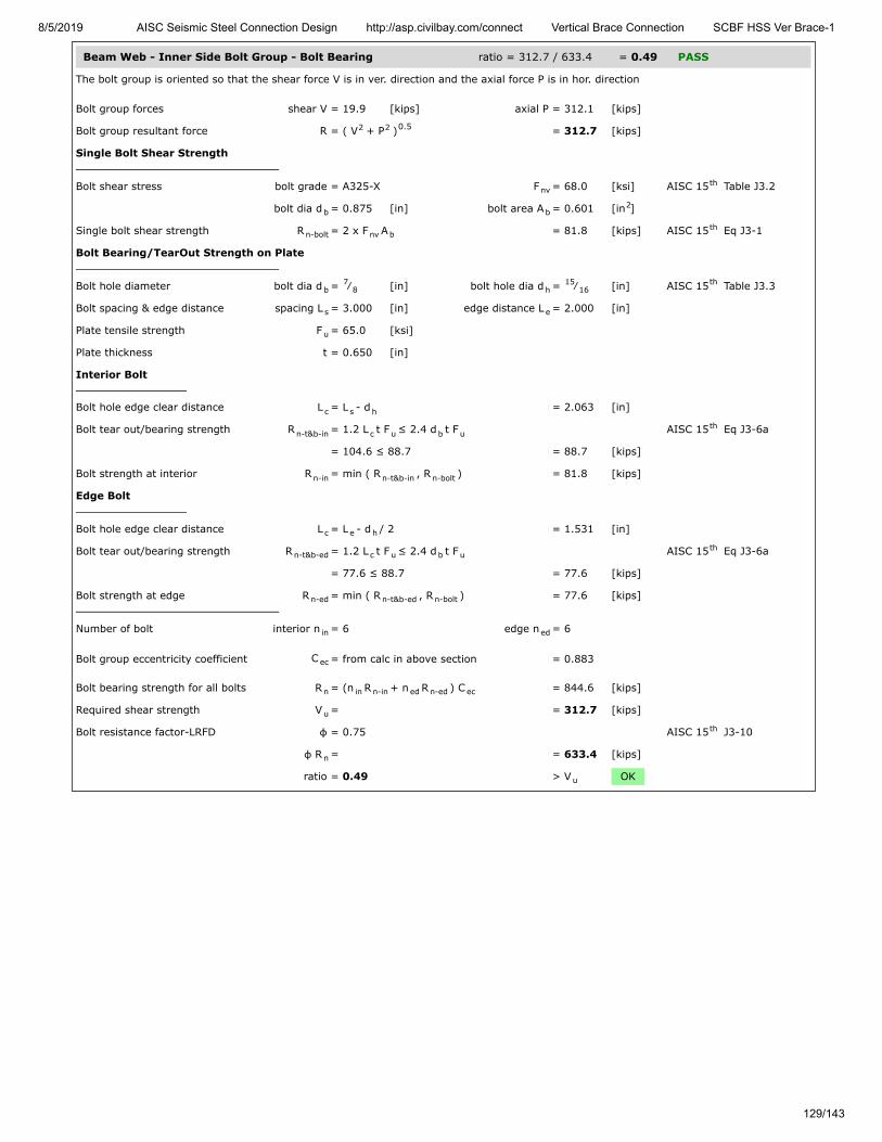
8/5/2019 AISC Seismic Steel Connection Design http://asp.civilbay.com/connect Vertical Brace Connection SCBF HSS Ver Brace-1
129/143
Beam Web - Inner Side Bolt Group - Bolt Bearing ratio = 312.7 / 633.4 = 0.49 PASS
The bolt group is oriented so that the shear force V is in ver. direction and the axial force P is in hor. direction
Bolt group forces shear V = 19.9 [kips] axial P = 312.1 [kips]
Bolt group resultant force R = ( V + P ) = 312.7 [kips]
Single Bolt Shear Strength
Bolt shear stress bolt grade = A325-X F = 68.0 [ksi] AISC 15 Table J3.2
bolt dia d = 0.875 [in] bolt area A = 0.601 [in ]
Single bolt shear strength R = 2 x F A = 81.8 [kips] AISC 15 Eq J3-1
Bolt Bearing/TearOut Strength on Plate
Bolt hole diameter bolt dia d = ⁄ [in] bolt hole dia d = ⁄ [in] AISC 15 Table J3.3
Bolt spacing & edge distance spacing L = 3.000 [in] edge distance L = 2.000 [in]
Plate tensile strength F = 65.0 [ksi]
Plate thickness t = 0.650 [in]
Interior Bolt
Bolt hole edge clear distance L = L - d = 2.063 [in]
Bolt tear out/bearing strength R = 1.2 L t F ≤ 2.4 d t F AISC 15 Eq J3-6a
= 104.6 ≤ 88.7 = 88.7 [kips]
Bolt strength at interior R = min ( R , R ) = 81.8 [kips]
Edge Bolt
Bolt hole edge clear distance L = L - d / 2 = 1.531 [in]
Bolt tear out/bearing strength R = 1.2 L t F ≤ 2.4 d t F AISC 15 Eq J3-6a
= 77.6 ≤ 88.7 = 77.6 [kips]
Bolt strength at edge R = min ( R , R ) = 77.6 [kips]
Number of bolt interior n = 6 edge n = 6
Bolt group eccentricity coefficient C = from calc in above section = 0.883
Bolt bearing strength for all bolts R = (n R + n R ) C = 844.6 [kips]
Required shear strength V = = 312.7 [kips]
Bolt resistance factor-LRFD φ = 0.75 AISC 15 J3-10
φ R = = 633.4 [kips]
ratio = 0.49 > V OK
2 2 0.5
nvth
b b2
n-bolt nv bth
b7
8 h15
16th
s e
u
c s h
n-t&b-in c u b uth
n-in n-t&b-in n-bolt
c e h
n-t&b-ed c u b uth
n-ed n-t&b-ed n-bolt
in ed
ec
n in n-in ed n-ed ec
u
th
n
u

8/5/2019 AISC Seismic Steel Connection Design http://asp.civilbay.com/connect Vertical Brace Connection SCBF HSS Ver Brace-1
130/143
Beam Web - Outer Side Bolt Group Eccentricity - Shear + Axial
Shear V - from user input, beam end shear reaction caused by gravity load onlyAxial P - from gusset interface forces calc , beam member axial load Pe - hor distance from the gusset-beam weld line CG point to the beam splice outer side bolt group CG point
Bolt group forces shear V = 19.9 [kips] axial P = 312.1 [kips]
Bolt group resultant force R = ( V + P ) = 312.7 [kips]
Resultant force to ver Y axis angle θ = tan (P / V) = 86.35 [°]
Bolt group row and column bolt row n = 6 bolt col n = 2
Bolt row/column spacing bolt row s = 3.000 [in] bolt col s = 3.000 [in]
Shear force to bolt group CG ecc e = = 20.125 [in]
Shear force to ver Y axis angle θ = = 86.35 [°]
Bolt group coefficient C C = from AISC 15 Table 7-6 ~ 7-13 = 9.943
Bolt group eccentricity coefficient C = C / ( n x n ) = 0.829
Beam Web - Outer Side Bolt Group - Bolt Shear ratio = 312.7 / 610.2 = 0.51 PASS
Bolt group forces shear V = 19.9 [kips] axial P = 312.1 [kips]
Bolt group resultant force R = ( V + P ) = 312.7 [kips]
Bolt shear stress bolt grade = A325-X F = 68.0 [ksi] AISC 15 Table J3.2
bolt dia d = 0.875 [in] bolt area A = 0.601 [in ]
Number of bolt carried shear n = 12.0 shear plane m = 2
Bolt group eccentricity coefficient C = from 'Bolt Group Eccentricity' calc = 0.829
Required shear strength V = = 312.7 [kips]
Bolt shear strength R = F A n m C = 813.5 [kips] AISC 15 Eq J3-1
Bolt resistance factor-LRFD φ = 0.75 AISC 15 Eq J3-1
φ R = = 610.2 [kips]
ratio = 0.51 > V OK
bm
x
2 2 0.5
-1
r c
r c
x
th
ec r c
2 2 0.5
nvth
b b2
s
ec
u
n nv b s ecth
th
n
u
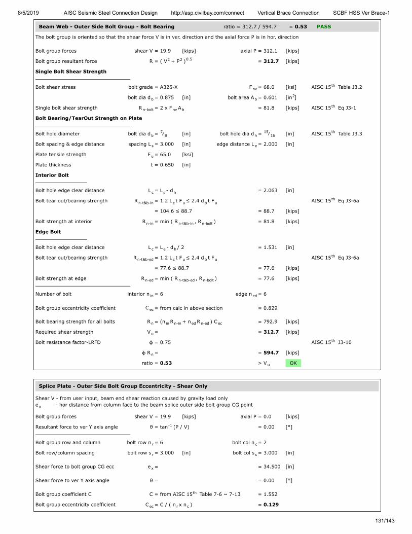
8/5/2019 AISC Seismic Steel Connection Design http://asp.civilbay.com/connect Vertical Brace Connection SCBF HSS Ver Brace-1
131/143
Beam Web - Outer Side Bolt Group - Bolt Bearing ratio = 312.7 / 594.7 = 0.53 PASS
The bolt group is oriented so that the shear force V is in ver. direction and the axial force P is in hor. direction
Bolt group forces shear V = 19.9 [kips] axial P = 312.1 [kips]
Bolt group resultant force R = ( V + P ) = 312.7 [kips]
Single Bolt Shear Strength
Bolt shear stress bolt grade = A325-X F = 68.0 [ksi] AISC 15 Table J3.2
bolt dia d = 0.875 [in] bolt area A = 0.601 [in ]
Single bolt shear strength R = 2 x F A = 81.8 [kips] AISC 15 Eq J3-1
Bolt Bearing/TearOut Strength on Plate
Bolt hole diameter bolt dia d = ⁄ [in] bolt hole dia d = ⁄ [in] AISC 15 Table J3.3
Bolt spacing & edge distance spacing L = 3.000 [in] edge distance L = 2.000 [in]
Plate tensile strength F = 65.0 [ksi]
Plate thickness t = 0.650 [in]
Interior Bolt
Bolt hole edge clear distance L = L - d = 2.063 [in]
Bolt tear out/bearing strength R = 1.2 L t F ≤ 2.4 d t F AISC 15 Eq J3-6a
= 104.6 ≤ 88.7 = 88.7 [kips]
Bolt strength at interior R = min ( R , R ) = 81.8 [kips]
Edge Bolt
Bolt hole edge clear distance L = L - d / 2 = 1.531 [in]
Bolt tear out/bearing strength R = 1.2 L t F ≤ 2.4 d t F AISC 15 Eq J3-6a
= 77.6 ≤ 88.7 = 77.6 [kips]
Bolt strength at edge R = min ( R , R ) = 77.6 [kips]
Number of bolt interior n = 6 edge n = 6
Bolt group eccentricity coefficient C = from calc in above section = 0.829
Bolt bearing strength for all bolts R = (n R + n R ) C = 792.9 [kips]
Required shear strength V = = 312.7 [kips]
Bolt resistance factor-LRFD φ = 0.75 AISC 15 J3-10
φ R = = 594.7 [kips]
ratio = 0.53 > V OK
Splice Plate - Outer Side Bolt Group Eccentricity - Shear Only
Shear V - from user input, beam end shear reaction caused by gravity load onlye - hor distance from column face to the beam splice outer side bolt group CG point
Bolt group forces shear V = 19.9 [kips] axial P = 0.0 [kips]
Resultant force to ver Y axis angle θ = tan (P / V) = 0.00 [°]
Bolt group row and column bolt row n = 6 bolt col n = 2
Bolt row/column spacing bolt row s = 3.000 [in] bolt col s = 3.000 [in]
Shear force to bolt group CG ecc e = = 34.500 [in]
Shear force to ver Y axis angle θ = = 0.00 [°]
Bolt group coefficient C C = from AISC 15 Table 7-6 ~ 7-13 = 1.552
Bolt group eccentricity coefficient C = C / ( n x n ) = 0.129
2 2 0.5
nvth
b b2
n-bolt nv bth
b7
8 h15
16th
s e
u
c s h
n-t&b-in c u b uth
n-in n-t&b-in n-bolt
c e h
n-t&b-ed c u b uth
n-ed n-t&b-ed n-bolt
in ed
ec
n in n-in ed n-ed ec
u
th
n
u
x
-1
r c
r c
x
th
ec r c

8/5/2019 AISC Seismic Steel Connection Design http://asp.civilbay.com/connect Vertical Brace Connection SCBF HSS Ver Brace-1
132/143
Splice Plate - Outer Side Bolt Group - Bolt Bearing ratio = 10.0 / 47.5 = 0.21 PASS
The bolt group is oriented so that the shear force V is in ver. direction and the axial force P is in hor. direction
Bolt group forces shear V = 10.0 [kips] axial P = 0.0 [kips]
Bolt group resultant force R = ( V + P ) = 10.0 [kips]
Single Bolt Shear Strength
Bolt shear stress bolt grade = A325-X F = 68.0 [ksi] AISC 15 Table J3.2
bolt dia d = 0.875 [in] bolt area A = 0.601 [in ]
Single bolt shear strength R = F A = 40.9 [kips] AISC 15 Eq J3-1
Bolt Bearing/TearOut Strength on Plate
Bolt hole diameter bolt dia d = ⁄ [in] bolt hole dia d = ⁄ [in] AISC 15 Table J3.3
Bolt spacing spacing L = 3.000 [in]
Plate tensile strength F = 65.0 [ksi]
Plate thickness t = 0.375 [in]
Interior Bolt
Bolt hole edge clear distance L = L - d = 2.063 [in]
Bolt tear out/bearing strength R = 1.2 L t F ≤ 2.4 d t m F AISC 15 Eq J3-6a
= 60.3 ≤ 51.2 = 51.2 [kips]
Bolt strength at interior R = min ( R , R ) = 40.9 [kips]
Number of bolt interior n = 12
Bolt group eccentricity coefficient C = from calc in above section = 0.129
Bolt bearing strength for all bolts R = (n R ) C = 63.3 [kips]
Required shear strength V = = 10.0 [kips]
Bolt resistance factor-LRFD φ = 0.75 AISC 15 J3-10
φ R = = 47.5 [kips]
ratio = 0.21 > V OK
2 2 0.5
nvth
b b2
n-bolt nv bth
b7
8 h15
16th
s
u
c s h
n-t&b-in c u b uth
n-in n-t&b-in n-bolt
in
ec
n in n-in ec
u
th
n
u

8/5/2019 AISC Seismic Steel Connection Design http://asp.civilbay.com/connect Vertical Brace Connection SCBF HSS Ver Brace-1
133/143
Splice Plate - Compression Buckling ratio = 156.1 / 256.1 = 0.61 PASS
Plate Compression Check
Plate size width b = 19.000 [in] thickness t = 0.375 [in]
F = 50.0 [ksi] E = 29000 [ksi]
Plate gross area in compression A = b t = 7.125 [in ]
Plate radius of gyration r = t / 12 = 0.108 [in]
Plate effective length factor K = = 1.20 AISC 15 Table C-A-7.1
Plate unbraced length L = = 5.000 [in]
Plate slenderness KL/r = 1.20 x L / r = 55.43
when KL
r > 25 , use Chapter E AISC 15 J4.4 (b)
Elastic buckling stress F = π E
( KL/r ) = 93.17 [ksi] AISC 15 Eq E3-4
when KL
r ≤ 4.71 (
E
F ) = 113.43 AISC 15 E3 (a)
Critical stress F = 0.658 F = 39.94 [ksi] AISC 15 Eq E3-2
Plate compression required P = 0.5 x beam axial compression P = 156.1 [kips]
Plate compression provided R = F x A = 284.6 [kips] AISC 15 Eq E3-1
Resistance factor-LRFD φ = 0.90 AISC 15 E1
φ R = = 256.1 [kips]
ratio = 0.61 > P OK
Splice Plate - Shear Yielding ratio = 19.9 / 427.5 = 0.05 PASS
Splice Plate Shear Yielding
Plate size width b = 19.000 [in] thickness t = 0.375 [in]
Plate yield strength F = 50.0 [ksi]
Plate gross area in shear A = b t x 2 side = 14.250 [in ]
Shear force required V = = 19.9 [kips]
Plate shear yielding strength R = 0.6 F A = 427.5 [kips] AISC 15 Eq J4-3
Resistance factor-LRFD φ = 1.00 AISC 15 Eq J4-3
φ R = = 427.5 [kips]
ratio = 0.05 > V OK
Splice Plate - Flexural Yielding ratio = 54.73 / 253.83 = 0.22 PASS
Plate width & thick width b = 19.000 [in] thick t = 0.375 [in]
yield F = 50.0 [ksi]
Beam end shear reaction caused bygravity load only
V = from user input = 19.9 [kips]
Ecc from column face to outer boltgroup first bolt line
e = = 33.000 [in]
Flexural strength required M = V x e = 54.73 [kip-ft]
Shear plate - plastic modulus Z = ( b x t ) / 4 x 2 side = 67.69 [in ]
Flexural strength available M = φ F Z φ=0.90 = 253.83 [kip-ft]
ratio = 0.22 > M OK
p p
y
g p p2
p √th
u
u
th
e
2
2th
y
0.5 th
cr( F / F )y e y
th
u
n cr gth
th
n
u
p p
y
gv p p2
u
n y gvth
th
n
u
p p
y
r
p p2p
3
c y p
r

8/5/2019 AISC Seismic Steel Connection Design http://asp.civilbay.com/connect Vertical Brace Connection SCBF HSS Ver Brace-1
134/143
Splice Plate - Shear Rupture ratio = 10.0 / 142.6 = 0.07 PASS
Plate Shear Rupture Check
Bolt hole diameter bolt dia d = ⁄ [in] bolt hole dia d = 1 [in] AISC 15 B4.3b
Number of bolt n = 6
Plate size width b = 19.000 [in] thickness t = 0.375 [in]
Plate tensile strength F = 65.0 [ksi]
Plate net area in shear A = ( b - n d ) t = 4.875 [in ]
Shear force required V = = 10.0 [kips]
Plate shear rupture strength R = 0.6 F A = 190.1 [kips] AISC 15 Eq J4-4
Resistance factor-LRFD φ = 0.75 AISC 15 Eq J4-4
φ R = = 142.6 [kips]
ratio = 0.07 > V OK
Splice Plate - Flexural Rupture ratio = 27.36 / 96.36 = 0.28 PASS
Plate A and Z Calc
Bolt hole diameter bolt dia d = ⁄ [in] bolt hole dia d = 1 [in] AISC 15 B4.3b
Number of bolt n = 6
Plate size width b = 19.000 [in] thickness t = 0.375 [in]
Plate net area A = ( b - n d ) t = 4.875 [in ]
Plate net plastic sect modulus Z = = 23.72 [in ]
Plate net elastic sect modulus S = = 16.33 [in ]
Plate width & thick width b = 19.000 [in] thick t = 0.375 [in]
F = 65.0 [ksi]
Beam end shear reaction caused bygravity load only
V = from user input, x 0.5 for 2 side plate = 10.0 [kips]
Ecc from column face to outer boltgroup first bolt line
e = = 33.000 [in]
Flexural strength required M = V x e = 27.36 [kip-ft]
Shear plate - net plastic modulus Z = from above calc = 23.72 [in ]
Flexural strength available M = φ F Z φ=0.75 = 96.36 [kip-ft]
ratio = 0.28 > M OK
Seismic SCBF LC4 shear V = 19.9 kips axial P = 312.7 kips (C) ratio = 0.61 PASS
Beam Web - Outer Side Bolt Group Eccentricity - Shear Only
Shear V - from user input, beam end shear reaction caused by gravity load onlye - hor distance from column face to the beam splice outer side bolt group CG point
Bolt group forces shear V = 19.9 [kips] axial P = 0.0 [kips]
Resultant force to ver Y axis angle θ = tan (P / V) = 0.00 [°]
Bolt group row and column bolt row n = 6 bolt col n = 2
Bolt row/column spacing bolt row s = 3.000 [in] bolt col s = 3.000 [in]
Shear force to bolt group CG ecc e = = 34.500 [in]
Shear force to ver Y axis angle θ = = 0.00 [°]
Bolt group coefficient C C = from AISC 15 Table 7-6 ~ 7-13 = 1.552
Bolt group eccentricity coefficient C = C / ( n x n ) = 0.129
b7
8 hth
p p
u
nv p h p2
u
n u nvth
th
n
u
n net
b7
8 hth
p p
n p h p2
net3
net3
p p
u
r
net3
c u net
r
x
-1
r c
r c
x
th
ec r c
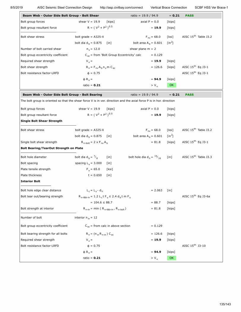
8/5/2019 AISC Seismic Steel Connection Design http://asp.civilbay.com/connect Vertical Brace Connection SCBF HSS Ver Brace-1
135/143
Beam Web - Outer Side Bolt Group - Bolt Shear ratio = 19.9 / 94.9 = 0.21 PASS
Bolt group forces shear V = 19.9 [kips] axial P = 0.0 [kips]
Bolt group resultant force R = ( V + P ) = 19.9 [kips]
Bolt shear stress bolt grade = A325-X F = 68.0 [ksi] AISC 15 Table J3.2
bolt dia d = 0.875 [in] bolt area A = 0.601 [in ]
Number of bolt carried shear n = 12.0 shear plane m = 2
Bolt group eccentricity coefficient C = from 'Bolt Group Eccentricity' calc = 0.129
Required shear strength V = = 19.9 [kips]
Bolt shear strength R = F A n m C = 126.6 [kips] AISC 15 Eq J3-1
Bolt resistance factor-LRFD φ = 0.75 AISC 15 Eq J3-1
φ R = = 94.9 [kips]
ratio = 0.21 > V OK
Beam Web - Outer Side Bolt Group - Bolt Bearing ratio = 19.9 / 94.9 = 0.21 PASS
The bolt group is oriented so that the shear force V is in ver. direction and the axial force P is in hor. direction
Bolt group forces shear V = 19.9 [kips] axial P = 0.0 [kips]
Bolt group resultant force R = ( V + P ) = 19.9 [kips]
Single Bolt Shear Strength
Bolt shear stress bolt grade = A325-X F = 68.0 [ksi] AISC 15 Table J3.2
bolt dia d = 0.875 [in] bolt area A = 0.601 [in ]
Single bolt shear strength R = 2 x F A = 81.8 [kips] AISC 15 Eq J3-1
Bolt Bearing/TearOut Strength on Plate
Bolt hole diameter bolt dia d = ⁄ [in] bolt hole dia d = ⁄ [in] AISC 15 Table J3.3
Bolt spacing spacing L = 3.000 [in]
Plate tensile strength F = 65.0 [ksi]
Plate thickness t = 0.650 [in]
Interior Bolt
Bolt hole edge clear distance L = L - d = 2.063 [in]
Bolt tear out/bearing strength R = 1.2 L t F ≤ 2.4 d t m F AISC 15 Eq J3-6a
= 104.6 ≤ 88.7 = 88.7 [kips]
Bolt strength at interior R = min ( R , R ) = 81.8 [kips]
Number of bolt interior n = 12
Bolt group eccentricity coefficient C = from calc in above section = 0.129
Bolt bearing strength for all bolts R = (n R ) C = 126.6 [kips]
Required shear strength V = = 19.9 [kips]
Bolt resistance factor-LRFD φ = 0.75 AISC 15 J3-10
φ R = = 94.9 [kips]
ratio = 0.21 > V OK
2 2 0.5
nvth
b b2
s
ec
u
n nv b s ecth
th
n
u
2 2 0.5
nvth
b b2
n-bolt nv bth
b7
8 h15
16th
s
u
c s h
n-t&b-in c u b uth
n-in n-t&b-in n-bolt
in
ec
n in n-in ec
u
th
n
u
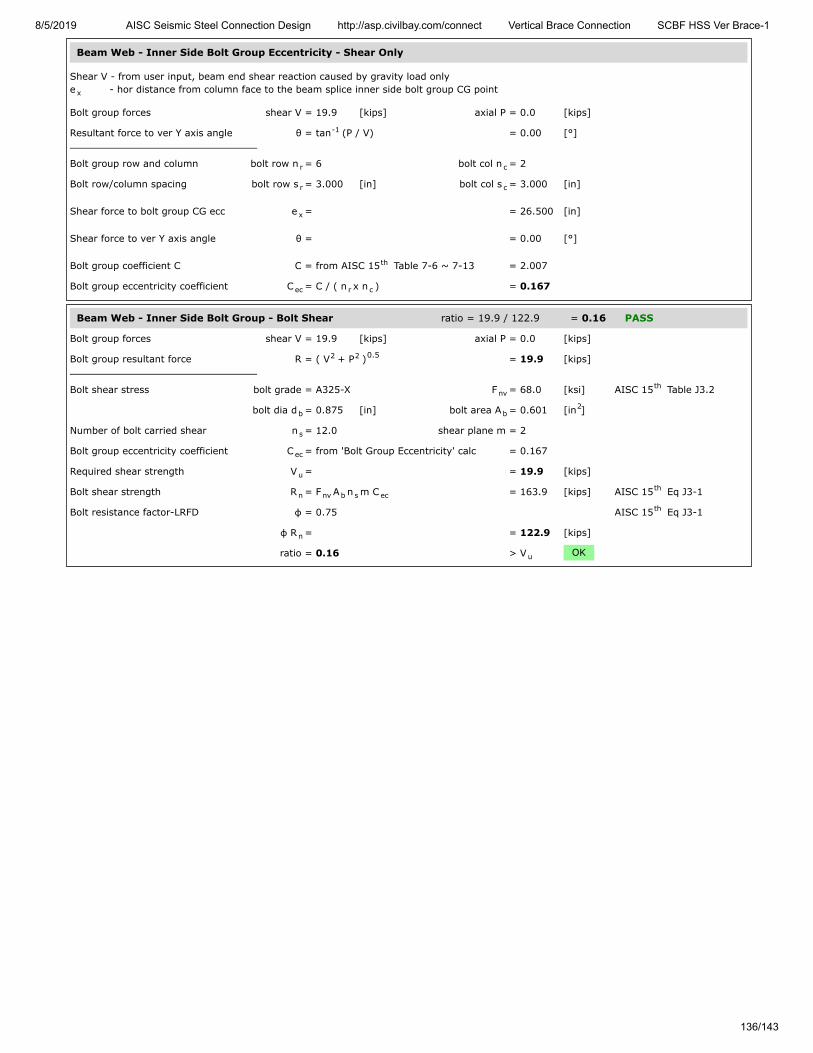
8/5/2019 AISC Seismic Steel Connection Design http://asp.civilbay.com/connect Vertical Brace Connection SCBF HSS Ver Brace-1
136/143
Beam Web - Inner Side Bolt Group Eccentricity - Shear Only
Shear V - from user input, beam end shear reaction caused by gravity load onlye - hor distance from column face to the beam splice inner side bolt group CG point
Bolt group forces shear V = 19.9 [kips] axial P = 0.0 [kips]
Resultant force to ver Y axis angle θ = tan (P / V) = 0.00 [°]
Bolt group row and column bolt row n = 6 bolt col n = 2
Bolt row/column spacing bolt row s = 3.000 [in] bolt col s = 3.000 [in]
Shear force to bolt group CG ecc e = = 26.500 [in]
Shear force to ver Y axis angle θ = = 0.00 [°]
Bolt group coefficient C C = from AISC 15 Table 7-6 ~ 7-13 = 2.007
Bolt group eccentricity coefficient C = C / ( n x n ) = 0.167
Beam Web - Inner Side Bolt Group - Bolt Shear ratio = 19.9 / 122.9 = 0.16 PASS
Bolt group forces shear V = 19.9 [kips] axial P = 0.0 [kips]
Bolt group resultant force R = ( V + P ) = 19.9 [kips]
Bolt shear stress bolt grade = A325-X F = 68.0 [ksi] AISC 15 Table J3.2
bolt dia d = 0.875 [in] bolt area A = 0.601 [in ]
Number of bolt carried shear n = 12.0 shear plane m = 2
Bolt group eccentricity coefficient C = from 'Bolt Group Eccentricity' calc = 0.167
Required shear strength V = = 19.9 [kips]
Bolt shear strength R = F A n m C = 163.9 [kips] AISC 15 Eq J3-1
Bolt resistance factor-LRFD φ = 0.75 AISC 15 Eq J3-1
φ R = = 122.9 [kips]
ratio = 0.16 > V OK
x
-1
r c
r c
x
th
ec r c
2 2 0.5
nvth
b b2
s
ec
u
n nv b s ecth
th
n
u

8/5/2019 AISC Seismic Steel Connection Design http://asp.civilbay.com/connect Vertical Brace Connection SCBF HSS Ver Brace-1
137/143
Beam Web - Inner Side Bolt Group - Bolt Bearing ratio = 19.9 / 122.9 = 0.16 PASS
The bolt group is oriented so that the shear force V is in ver. direction and the axial force P is in hor. direction
Bolt group forces shear V = 19.9 [kips] axial P = 0.0 [kips]
Bolt group resultant force R = ( V + P ) = 19.9 [kips]
Single Bolt Shear Strength
Bolt shear stress bolt grade = A325-X F = 68.0 [ksi] AISC 15 Table J3.2
bolt dia d = 0.875 [in] bolt area A = 0.601 [in ]
Single bolt shear strength R = 2 x F A = 81.8 [kips] AISC 15 Eq J3-1
Bolt Bearing/TearOut Strength on Plate
Bolt hole diameter bolt dia d = ⁄ [in] bolt hole dia d = ⁄ [in] AISC 15 Table J3.3
Bolt spacing spacing L = 3.000 [in]
Plate tensile strength F = 65.0 [ksi]
Plate thickness t = 0.650 [in]
Interior Bolt
Bolt hole edge clear distance L = L - d = 2.063 [in]
Bolt tear out/bearing strength R = 1.2 L t F ≤ 2.4 d t m F AISC 15 Eq J3-6a
= 104.6 ≤ 88.7 = 88.7 [kips]
Bolt strength at interior R = min ( R , R ) = 81.8 [kips]
Number of bolt interior n = 12
Bolt group eccentricity coefficient C = from calc in above section = 0.167
Bolt bearing strength for all bolts R = (n R ) C = 163.9 [kips]
Required shear strength V = = 19.9 [kips]
Bolt resistance factor-LRFD φ = 0.75 AISC 15 J3-10
φ R = = 122.9 [kips]
ratio = 0.16 > V OK
Beam Web - Inner Side Bolt Group Eccentricity - Shear + Axial
Shear V - from user input, beam end shear reaction caused by gravity load onlyAxial P - from gusset interface forces calc , beam member axial load Pe - hor distance from the gusset-beam weld line CG point to the beam splice inner side bolt group CG point
Bolt group forces shear V = 19.9 [kips] axial P = 312.7 [kips]
Bolt group resultant force R = ( V + P ) = 313.3 [kips]
Resultant force to ver Y axis angle θ = tan (P / V) = 86.36 [°]
Bolt group row and column bolt row n = 6 bolt col n = 2
Bolt row/column spacing bolt row s = 3.000 [in] bolt col s = 3.000 [in]
Shear force to bolt group CG ecc e = = 12.125 [in]
Shear force to ver Y axis angle θ = = 86.36 [°]
Bolt group coefficient C C = from AISC 15 Table 7-6 ~ 7-13 = 10.597
Bolt group eccentricity coefficient C = C / ( n x n ) = 0.883
2 2 0.5
nvth
b b2
n-bolt nv bth
b7
8 h15
16th
s
u
c s h
n-t&b-in c u b uth
n-in n-t&b-in n-bolt
in
ec
n in n-in ec
u
th
n
u
bm
x
2 2 0.5
-1
r c
r c
x
th
ec r c

8/5/2019 AISC Seismic Steel Connection Design http://asp.civilbay.com/connect Vertical Brace Connection SCBF HSS Ver Brace-1
138/143
Beam Web - Inner Side Bolt Group - Bolt Shear ratio = 313.3 / 649.9 = 0.48 PASS
Bolt group forces shear V = 19.9 [kips] axial P = 312.7 [kips]
Bolt group resultant force R = ( V + P ) = 313.3 [kips]
Bolt shear stress bolt grade = A325-X F = 68.0 [ksi] AISC 15 Table J3.2
bolt dia d = 0.875 [in] bolt area A = 0.601 [in ]
Number of bolt carried shear n = 12.0 shear plane m = 2
Bolt group eccentricity coefficient C = from 'Bolt Group Eccentricity' calc = 0.883
Required shear strength V = = 313.3 [kips]
Bolt shear strength R = F A n m C = 866.5 [kips] AISC 15 Eq J3-1
Bolt resistance factor-LRFD φ = 0.75 AISC 15 Eq J3-1
φ R = = 649.9 [kips]
ratio = 0.48 > V OK
Beam Web - Inner Side Bolt Group - Bolt Bearing ratio = 313.3 / 633.4 = 0.49 PASS
The bolt group is oriented so that the shear force V is in ver. direction and the axial force P is in hor. direction
Bolt group forces shear V = 19.9 [kips] axial P = 312.7 [kips]
Bolt group resultant force R = ( V + P ) = 313.3 [kips]
Single Bolt Shear Strength
Bolt shear stress bolt grade = A325-X F = 68.0 [ksi] AISC 15 Table J3.2
bolt dia d = 0.875 [in] bolt area A = 0.601 [in ]
Single bolt shear strength R = 2 x F A = 81.8 [kips] AISC 15 Eq J3-1
Bolt Bearing/TearOut Strength on Plate
Bolt hole diameter bolt dia d = ⁄ [in] bolt hole dia d = ⁄ [in] AISC 15 Table J3.3
Bolt spacing & edge distance spacing L = 3.000 [in] edge distance L = 2.000 [in]
Plate tensile strength F = 65.0 [ksi]
Plate thickness t = 0.650 [in]
Interior Bolt
Bolt hole edge clear distance L = L - d = 2.063 [in]
Bolt tear out/bearing strength R = 1.2 L t F ≤ 2.4 d t F AISC 15 Eq J3-6a
= 104.6 ≤ 88.7 = 88.7 [kips]
Bolt strength at interior R = min ( R , R ) = 81.8 [kips]
Edge Bolt
Bolt hole edge clear distance L = L - d / 2 = 1.531 [in]
Bolt tear out/bearing strength R = 1.2 L t F ≤ 2.4 d t F AISC 15 Eq J3-6a
= 77.6 ≤ 88.7 = 77.6 [kips]
Bolt strength at edge R = min ( R , R ) = 77.6 [kips]
Number of bolt interior n = 6 edge n = 6
Bolt group eccentricity coefficient C = from calc in above section = 0.883
Bolt bearing strength for all bolts R = (n R + n R ) C = 844.6 [kips]
Required shear strength V = = 313.3 [kips]
Bolt resistance factor-LRFD φ = 0.75 AISC 15 J3-10
φ R = = 633.4 [kips]
ratio = 0.49 > V OK
2 2 0.5
nvth
b b2
s
ec
u
n nv b s ecth
th
n
u
2 2 0.5
nvth
b b2
n-bolt nv bth
b7
8 h15
16th
s e
u
c s h
n-t&b-in c u b uth
n-in n-t&b-in n-bolt
c e h
n-t&b-ed c u b uth
n-ed n-t&b-ed n-bolt
in ed
ec
n in n-in ed n-ed ec
u
th
n
u
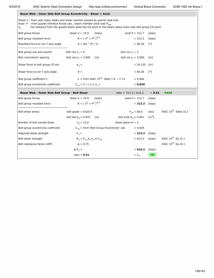
8/5/2019 AISC Seismic Steel Connection Design http://asp.civilbay.com/connect Vertical Brace Connection SCBF HSS Ver Brace-1
139/143
Beam Web - Outer Side Bolt Group Eccentricity - Shear + Axial
Shear V - from user input, beam end shear reaction caused by gravity load onlyAxial P - from gusset interface forces calc , beam member axial load Pe - hor distance from the gusset-beam weld line CG point to the beam splice outer side bolt group CG point
Bolt group forces shear V = 19.9 [kips] axial P = 312.7 [kips]
Bolt group resultant force R = ( V + P ) = 313.3 [kips]
Resultant force to ver Y axis angle θ = tan (P / V) = 86.36 [°]
Bolt group row and column bolt row n = 6 bolt col n = 2
Bolt row/column spacing bolt row s = 3.000 [in] bolt col s = 3.000 [in]
Shear force to bolt group CG ecc e = = 20.125 [in]
Shear force to ver Y axis angle θ = = 86.36 [°]
Bolt group coefficient C C = from AISC 15 Table 7-6 ~ 7-13 = 9.946
Bolt group eccentricity coefficient C = C / ( n x n ) = 0.829
Beam Web - Outer Side Bolt Group - Bolt Shear ratio = 313.3 / 610.2 = 0.51 PASS
Bolt group forces shear V = 19.9 [kips] axial P = 312.7 [kips]
Bolt group resultant force R = ( V + P ) = 313.3 [kips]
Bolt shear stress bolt grade = A325-X F = 68.0 [ksi] AISC 15 Table J3.2
bolt dia d = 0.875 [in] bolt area A = 0.601 [in ]
Number of bolt carried shear n = 12.0 shear plane m = 2
Bolt group eccentricity coefficient C = from 'Bolt Group Eccentricity' calc = 0.829
Required shear strength V = = 313.3 [kips]
Bolt shear strength R = F A n m C = 813.5 [kips] AISC 15 Eq J3-1
Bolt resistance factor-LRFD φ = 0.75 AISC 15 Eq J3-1
φ R = = 610.2 [kips]
ratio = 0.51 > V OK
bm
x
2 2 0.5
-1
r c
r c
x
th
ec r c
2 2 0.5
nvth
b b2
s
ec
u
n nv b s ecth
th
n
u

8/5/2019 AISC Seismic Steel Connection Design http://asp.civilbay.com/connect Vertical Brace Connection SCBF HSS Ver Brace-1
140/143
Beam Web - Outer Side Bolt Group - Bolt Bearing ratio = 313.3 / 594.7 = 0.53 PASS
The bolt group is oriented so that the shear force V is in ver. direction and the axial force P is in hor. direction
Bolt group forces shear V = 19.9 [kips] axial P = 312.7 [kips]
Bolt group resultant force R = ( V + P ) = 313.3 [kips]
Single Bolt Shear Strength
Bolt shear stress bolt grade = A325-X F = 68.0 [ksi] AISC 15 Table J3.2
bolt dia d = 0.875 [in] bolt area A = 0.601 [in ]
Single bolt shear strength R = 2 x F A = 81.8 [kips] AISC 15 Eq J3-1
Bolt Bearing/TearOut Strength on Plate
Bolt hole diameter bolt dia d = ⁄ [in] bolt hole dia d = ⁄ [in] AISC 15 Table J3.3
Bolt spacing & edge distance spacing L = 3.000 [in] edge distance L = 2.000 [in]
Plate tensile strength F = 65.0 [ksi]
Plate thickness t = 0.650 [in]
Interior Bolt
Bolt hole edge clear distance L = L - d = 2.063 [in]
Bolt tear out/bearing strength R = 1.2 L t F ≤ 2.4 d t F AISC 15 Eq J3-6a
= 104.6 ≤ 88.7 = 88.7 [kips]
Bolt strength at interior R = min ( R , R ) = 81.8 [kips]
Edge Bolt
Bolt hole edge clear distance L = L - d / 2 = 1.531 [in]
Bolt tear out/bearing strength R = 1.2 L t F ≤ 2.4 d t F AISC 15 Eq J3-6a
= 77.6 ≤ 88.7 = 77.6 [kips]
Bolt strength at edge R = min ( R , R ) = 77.6 [kips]
Number of bolt interior n = 6 edge n = 6
Bolt group eccentricity coefficient C = from calc in above section = 0.829
Bolt bearing strength for all bolts R = (n R + n R ) C = 792.9 [kips]
Required shear strength V = = 313.3 [kips]
Bolt resistance factor-LRFD φ = 0.75 AISC 15 J3-10
φ R = = 594.7 [kips]
ratio = 0.53 > V OK
Splice Plate - Outer Side Bolt Group Eccentricity - Shear Only
Shear V - from user input, beam end shear reaction caused by gravity load onlye - hor distance from column face to the beam splice outer side bolt group CG point
Bolt group forces shear V = 19.9 [kips] axial P = 0.0 [kips]
Resultant force to ver Y axis angle θ = tan (P / V) = 0.00 [°]
Bolt group row and column bolt row n = 6 bolt col n = 2
Bolt row/column spacing bolt row s = 3.000 [in] bolt col s = 3.000 [in]
Shear force to bolt group CG ecc e = = 34.500 [in]
Shear force to ver Y axis angle θ = = 0.00 [°]
Bolt group coefficient C C = from AISC 15 Table 7-6 ~ 7-13 = 1.552
Bolt group eccentricity coefficient C = C / ( n x n ) = 0.129
2 2 0.5
nvth
b b2
n-bolt nv bth
b7
8 h15
16th
s e
u
c s h
n-t&b-in c u b uth
n-in n-t&b-in n-bolt
c e h
n-t&b-ed c u b uth
n-ed n-t&b-ed n-bolt
in ed
ec
n in n-in ed n-ed ec
u
th
n
u
x
-1
r c
r c
x
th
ec r c
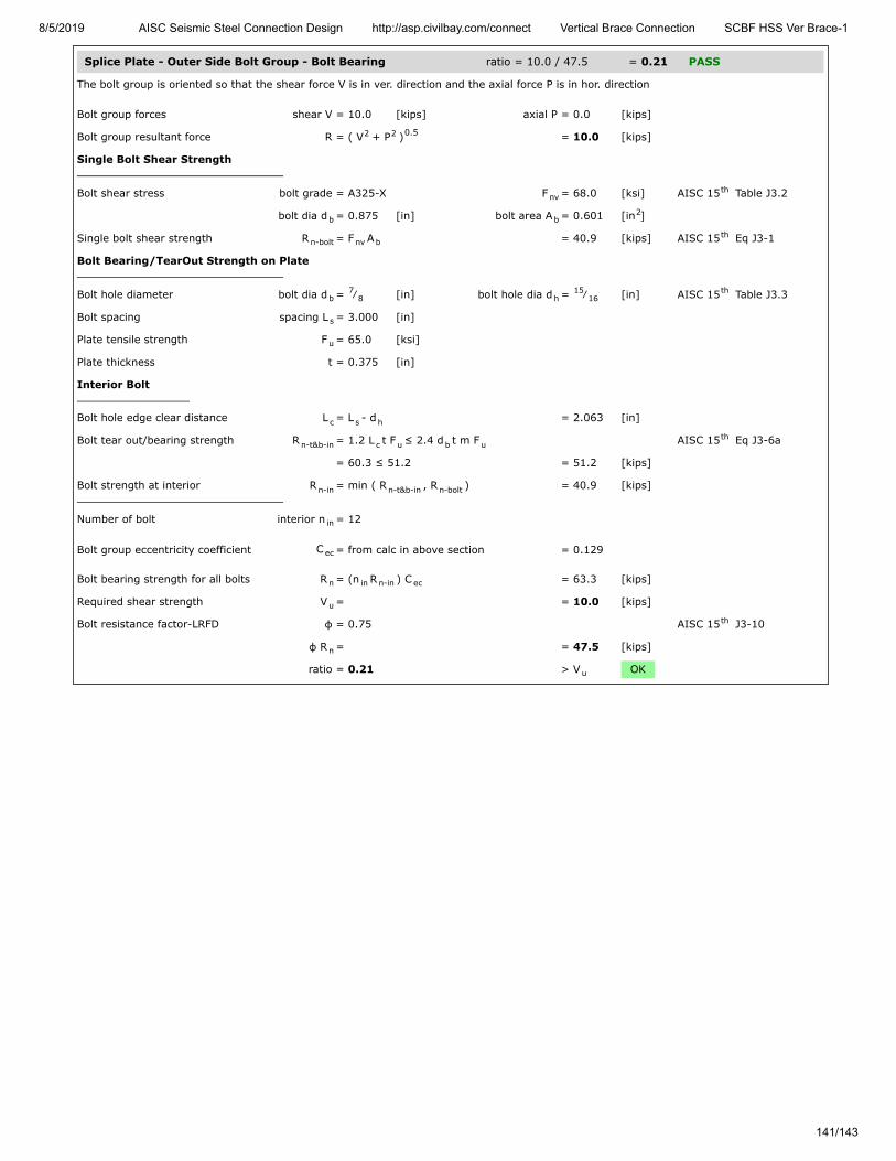
8/5/2019 AISC Seismic Steel Connection Design http://asp.civilbay.com/connect Vertical Brace Connection SCBF HSS Ver Brace-1
141/143
Splice Plate - Outer Side Bolt Group - Bolt Bearing ratio = 10.0 / 47.5 = 0.21 PASS
The bolt group is oriented so that the shear force V is in ver. direction and the axial force P is in hor. direction
Bolt group forces shear V = 10.0 [kips] axial P = 0.0 [kips]
Bolt group resultant force R = ( V + P ) = 10.0 [kips]
Single Bolt Shear Strength
Bolt shear stress bolt grade = A325-X F = 68.0 [ksi] AISC 15 Table J3.2
bolt dia d = 0.875 [in] bolt area A = 0.601 [in ]
Single bolt shear strength R = F A = 40.9 [kips] AISC 15 Eq J3-1
Bolt Bearing/TearOut Strength on Plate
Bolt hole diameter bolt dia d = ⁄ [in] bolt hole dia d = ⁄ [in] AISC 15 Table J3.3
Bolt spacing spacing L = 3.000 [in]
Plate tensile strength F = 65.0 [ksi]
Plate thickness t = 0.375 [in]
Interior Bolt
Bolt hole edge clear distance L = L - d = 2.063 [in]
Bolt tear out/bearing strength R = 1.2 L t F ≤ 2.4 d t m F AISC 15 Eq J3-6a
= 60.3 ≤ 51.2 = 51.2 [kips]
Bolt strength at interior R = min ( R , R ) = 40.9 [kips]
Number of bolt interior n = 12
Bolt group eccentricity coefficient C = from calc in above section = 0.129
Bolt bearing strength for all bolts R = (n R ) C = 63.3 [kips]
Required shear strength V = = 10.0 [kips]
Bolt resistance factor-LRFD φ = 0.75 AISC 15 J3-10
φ R = = 47.5 [kips]
ratio = 0.21 > V OK
2 2 0.5
nvth
b b2
n-bolt nv bth
b7
8 h15
16th
s
u
c s h
n-t&b-in c u b uth
n-in n-t&b-in n-bolt
in
ec
n in n-in ec
u
th
n
u

8/5/2019 AISC Seismic Steel Connection Design http://asp.civilbay.com/connect Vertical Brace Connection SCBF HSS Ver Brace-1
142/143
Splice Plate - Compression Buckling ratio = 156.4 / 256.1 = 0.61 PASS
Plate Compression Check
Plate size width b = 19.000 [in] thickness t = 0.375 [in]
F = 50.0 [ksi] E = 29000 [ksi]
Plate gross area in compression A = b t = 7.125 [in ]
Plate radius of gyration r = t / 12 = 0.108 [in]
Plate effective length factor K = = 1.20 AISC 15 Table C-A-7.1
Plate unbraced length L = = 5.000 [in]
Plate slenderness KL/r = 1.20 x L / r = 55.43
when KL
r > 25 , use Chapter E AISC 15 J4.4 (b)
Elastic buckling stress F = π E
( KL/r ) = 93.17 [ksi] AISC 15 Eq E3-4
when KL
r ≤ 4.71 (
E
F ) = 113.43 AISC 15 E3 (a)
Critical stress F = 0.658 F = 39.94 [ksi] AISC 15 Eq E3-2
Plate compression required P = 0.5 x beam axial compression P = 156.4 [kips]
Plate compression provided R = F x A = 284.6 [kips] AISC 15 Eq E3-1
Resistance factor-LRFD φ = 0.90 AISC 15 E1
φ R = = 256.1 [kips]
ratio = 0.61 > P OK
Splice Plate - Shear Yielding ratio = 19.9 / 427.5 = 0.05 PASS
Splice Plate Shear Yielding
Plate size width b = 19.000 [in] thickness t = 0.375 [in]
Plate yield strength F = 50.0 [ksi]
Plate gross area in shear A = b t x 2 side = 14.250 [in ]
Shear force required V = = 19.9 [kips]
Plate shear yielding strength R = 0.6 F A = 427.5 [kips] AISC 15 Eq J4-3
Resistance factor-LRFD φ = 1.00 AISC 15 Eq J4-3
φ R = = 427.5 [kips]
ratio = 0.05 > V OK
Splice Plate - Flexural Yielding ratio = 54.73 / 253.83 = 0.22 PASS
Plate width & thick width b = 19.000 [in] thick t = 0.375 [in]
yield F = 50.0 [ksi]
Beam end shear reaction caused bygravity load only
V = from user input = 19.9 [kips]
Ecc from column face to outer boltgroup first bolt line
e = = 33.000 [in]
Flexural strength required M = V x e = 54.73 [kip-ft]
Shear plate - plastic modulus Z = ( b x t ) / 4 x 2 side = 67.69 [in ]
Flexural strength available M = φ F Z φ=0.90 = 253.83 [kip-ft]
ratio = 0.22 > M OK
p p
y
g p p2
p √th
u
u
th
e
2
2th
y
0.5 th
cr( F / F )y e y
th
u
n cr gth
th
n
u
p p
y
gv p p2
u
n y gvth
th
n
u
p p
y
r
p p2p
3
c y p
r
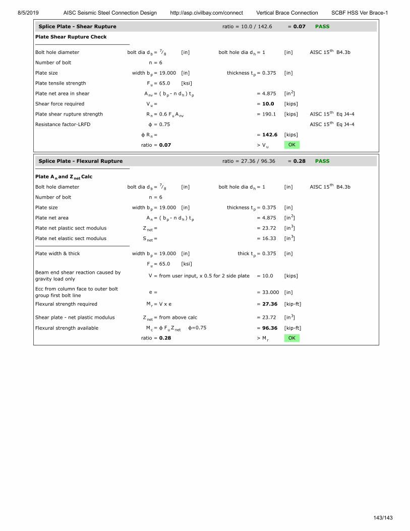
8/5/2019 AISC Seismic Steel Connection Design http://asp.civilbay.com/connect Vertical Brace Connection SCBF HSS Ver Brace-1
143/143
Splice Plate - Shear Rupture ratio = 10.0 / 142.6 = 0.07 PASS
Plate Shear Rupture Check
Bolt hole diameter bolt dia d = ⁄ [in] bolt hole dia d = 1 [in] AISC 15 B4.3b
Number of bolt n = 6
Plate size width b = 19.000 [in] thickness t = 0.375 [in]
Plate tensile strength F = 65.0 [ksi]
Plate net area in shear A = ( b - n d ) t = 4.875 [in ]
Shear force required V = = 10.0 [kips]
Plate shear rupture strength R = 0.6 F A = 190.1 [kips] AISC 15 Eq J4-4
Resistance factor-LRFD φ = 0.75 AISC 15 Eq J4-4
φ R = = 142.6 [kips]
ratio = 0.07 > V OK
Splice Plate - Flexural Rupture ratio = 27.36 / 96.36 = 0.28 PASS
Plate A and Z Calc
Bolt hole diameter bolt dia d = ⁄ [in] bolt hole dia d = 1 [in] AISC 15 B4.3b
Number of bolt n = 6
Plate size width b = 19.000 [in] thickness t = 0.375 [in]
Plate net area A = ( b - n d ) t = 4.875 [in ]
Plate net plastic sect modulus Z = = 23.72 [in ]
Plate net elastic sect modulus S = = 16.33 [in ]
Plate width & thick width b = 19.000 [in] thick t = 0.375 [in]
F = 65.0 [ksi]
Beam end shear reaction caused bygravity load only
V = from user input, x 0.5 for 2 side plate = 10.0 [kips]
Ecc from column face to outer boltgroup first bolt line
e = = 33.000 [in]
Flexural strength required M = V x e = 27.36 [kip-ft]
Shear plate - net plastic modulus Z = from above calc = 23.72 [in ]
Flexural strength available M = φ F Z φ=0.75 = 96.36 [kip-ft]
ratio = 0.28 > M OK
b7
8 hth
p p
u
nv p h p2
u
n u nvth
th
n
u
n net
b7
8 hth
p p
n p h p2
net3
net3
p p
u
r
net3
c u net
r


