8500 3-STACK MULTI-GYM...8500 3-STACK MULTI-GYM Part # 6965401 8500104 Rev. C 1 Revision: 08/29/01...
35
8500 3-STACK MULTI-GYM Part # 6965401 8500104 Rev. C Revision: 08/29/01 1 ASSEMBLY INSTRUCTIONS
Transcript of 8500 3-STACK MULTI-GYM...8500 3-STACK MULTI-GYM Part # 6965401 8500104 Rev. C 1 Revision: 08/29/01...
8500 3-STACK MULTI-GYM
Part # 6965401 8500104
Rev. C
Revision: 08/29/011
ASSEMBLY INSTRUCTIONS
IMPORTANT NOTESPlease note:
Tools Required for Assembly
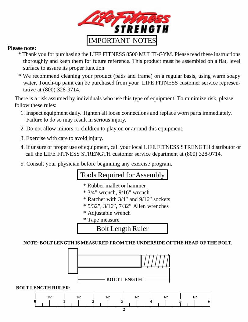
* Thank you for purchasing the LIFE FITNESS 8500 MULTI-GYM. Please read these instructionsthoroughly and keep them for future reference. This product must be assembled on a flat, levelsurface to assure its proper function.
* Rubber mallet or hammer* 3/4” wrench, 9/16” wrench* Ratchet with 3/4” and 9/16” sockets* 5/32”, 3/16”, 7/32” Allen wrenches* Adjustable wrench* Tape measure
2
NOTE: BOLT LENGTH IS MEASURED FROM THE UNDERSIDE OF THE HEAD OF THE BOLT.
BOLT LENGTH RULER:
* We recommend cleaning your product (pads and frame) on a regular basis, using warm soapywater. Touch-up paint can be purchased from your LIFE FITNESS customer service represen-tative at (800) 328-9714.
Bolt Length Ruler
0 1 2 3 4 5 61/2 1/2 1/2 1/2 1/2 1/2
BOLT LENGTH
There is a risk assumed by individuals who use this type of equipment. To minimize risk, pleasefollow these rules:
2. Do not allow minors or children to play on or around this equipment.
1. Inspect equipment daily. Tighten all loose connections and replace worn parts immediately. Failure to do so may result in serious injury.
3. Exercise with care to avoid injury.4. If unsure of proper use of equipment, call your local LIFE FITNESS STRENGTH distributor or
call the LIFE FITNESS STRENGTH customer service department at (800) 328-9714.
5. Consult your physician before beginning any exercise program.

3
PART #66171036779802662550266242026624302
662290366230036623503662450266225036620903669180366924026623702666220366623036628302627530265234016765203676530367699036768003676790367690036769702676980367721026768803676850367692036965503687250267710036770102687170267683036770703677220167723016764901677310169624016773301695490167735013108002311610132023016284501638970166193016714601311600165947026651602686870261227023118401
KEY1234567891011121314151617181920212223242526272829303132333435363738394041424344454647484950515253545556575859
QTY111111111111111111611111111211112111111181111182423113312121
PART #6140701617700164120016466901695470366926016781601675770131038016480301602060131049016619501310960260759066214401640640166950013103302310330431025013114502310280231028073102502310280131028043202401310290131029333102922310291531029063202101310291031029183102917320210732021056780101678000167803016780201678040167806016780501621450167038016189501638230163758016779703677950367796013102909310840468270016122704
DESCRIPTION1 X 1” GLIDE
2-1/2 X 5-1/2 NON-SKID STRIP3/8 X 2-3/4” DIA. SPRING PIN1/2 X 3-1/2” DIA. SPRING PIN
AB PULLEY PLATE3 X 2” END CAP
1/2 X 7-7/8” SPRING PIN2-7/8 X 1” CABLE CLIP
5/16” SNAP LINK3/8” FLANGE SPACER
1/2” FLANGE BEARING3/4” FLANGE BEARING3/4” SLEEVE BEARING
1/2” PAL NUT12 LINK CHAIN
WEIGHT STACK PINHINGE TAB
3/4” DIA. TAPPED SHAFT13/16” SHAFT COLLAR1-5/16” SHAFT COLLAR
3/8” WASHER3/8” LOCK WASHER
3/8” LOCK NUT3/8” LOW HEIGHT LOCK NUT
1/2” WASHER1/2” LOCK NUT
1/2” LOW HEIGHT LOCK NUT3/8 X 1” BTTN HD CAP SCREW
3/8 X 1-1/4” BOLT3/8 X 2” BOLT
3/8 X 2-3/4” BOLT3/8 X 3-1/4” BOLT
3/8 X 4” BOLT1/2 X 1-1/4” BOLT
1/2 X 3” BOLT1/2 X 3-1/4” BOLT
1/2 X 4” BOLT1/2 X 6-1/2” BOLT1/2 X 7-1/2” BOLT
PEC ARM PADPRESS SEAT PADPRESS BACK PAD
LEG SEAT PADLEG BACK PADPEC SEAT PADPEC BACK PADWEIGHT PLATE
WEIGHT PLATE LABELS (LBS.)WEIGHT PLATE LABELS (1-25)
WEIGHT PLATE BUSHING (10 CT)AB CRUNCH STRAP
LEG SHROUDPEC SHROUD
PRESS SHROUD3/8 X 1” BOLT
3/8 X 3” COUNTERSUNK BOLT2-7/8 X 2-1/4” CABLE CLIP
1/4” SPACER
QTY5461221
124
244621134168
675
413
212484
151416164278
10212111111
6011
121111
12284
DESCRIPTIONREAR UPRIGHT
LEG BACK PAD ADJUSTLEG BACK PAD SUPPORTBACK PAD ANGLE LEFT
BACK PAD ANGLE RIGHTPEC ARM RIGHTPEC ARM LEFT
PRESS ARMCALF/LOW ROW
BEARING HOUSINGFLOATING PULLEY STOP
SEAT SUPPORTPAD SUPPORT
WOLFF SLEEVELEG EXT HANDLE RIGHTLEG EXT HANDLE LEFT
2 X 8” PLATELAT BAR
72-3/8” GUIDE RODPRESS G.R. SUPPORT
LEG G.R. SUPPORTPEC G.R. SUPPORT
LEG WT. STACK BASEPRESS WT. STACK BASE
BASEPULLEY BRACKET
CENTER PULLEY BRACKETPEC CAM
FRONT UPRIGHTTOP BOOM
REAR BASE LEGLEG CURL/EXTENSION
PAD SLEEVELEG FRAME
SWIVEL PULLEY BRACKETPRESS ARM ADJUST
PRESS FRAMEPRESS BASE19-1/4” TUBE21-1/2” TUBE
4 X 7” ROLLER PADLAT CABLE ASSEMBLYLEG CABLE ASSEMBLY
PRESS CABLE ASSEMBLYAB CRUNCH CABLE ASSEMBLY
PEC DEC CABLE ASSEMBLYWEIGHT STACK CUSHION
4-1/2” PULLEYPILLOW BLOCK BEARING
20 HOLE SELECTOR SHAFTLOW ROW CHROME BAR
U-PINHEAD PLATE
1-1/4” SQ. RUBBER BUMPERFLOATING PULLEY BRACKET
2 X 15-1/2” PLATE4-1/2 X 8” PLATE
3/8 X 1/2” SPACER4” VINYL CAP
KEY60616263646566676869707172737475767778798081828384858687888990919293949596979899
100101102103104105106107108109110111112113114115116118
PARTS LIST
4
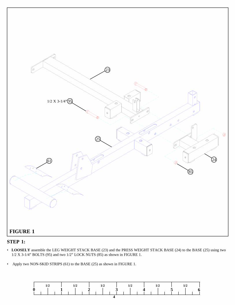
STEP 1:
FIGURE 1
0 1 2 3 4 5 61/2 1/2 1/2 1/2 1/2 1/2
• LOOSELY assemble the LEG WEIGHT STACK BASE (23) and the PRESS WEIGHT STACK BASE (24) to the BASE (25) using two1/2 X 3-1/4” BOLTS (95) and two 1/2” LOCK NUTS (85) as shown in FIGURE 1.
• Apply two NON-SKID STRIPS (61) to the BASE (25) as shown in FIGURE 1.
1/2 X 3-1/4” 95
24
25
85
61
23

STEP 2:FIGURE 2
5
• LOOSELY assemble the FRONT UPRIGHT (29) to the BASE (25) using two 1/2 X 3-1/4” BOLTS (95) and two 1/2” LOCK NUTS (85)as shown in FIGURE 2.
• LOOSELY assemble the REAR UPRIGHT (1) to the BASE (25) using one 1/2 X 3” BOLT (94), two 1/2” WASHERS (84), and one 1/2”LOCK NUT (85) as shown in FIGURE 2.
• LOOSELY assemble the TOP BOOM (30) to the FRONT UPRIGHT (29) using two 1/2 X 3-1/4” BOLTS (95) and two 1/2” LOCK NUTS(85) as shown in FIGURE 2.
• LOOSELY assemble the TOP BOOM (30) to the REAR UPRIGHT (1) using two 1/2 X 4” BOLTS (96), two 1/2” WASHERS (84), andone 1/2” LOCK NUT (85) as shown in FIGURE 2.
TIGTEN ALL LOOSE FRAME CONNECTIONS MADE TO THIS POINT!
2585
85
84
1
84
85
30
85
95 1/2 X 3-1/4”
95 1/2 X 3-1/4”
94 1/2 X 3”
96 1/2 X 4””
29
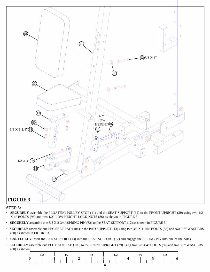
STEP 3:
FIGURE 3
6
0 1 2 3 4 5 61/2 1/2 1/2 1/2 1/2 1/2
• SECURELY assemble the FLOATING PULLEY STOP (11) and the SEAT SUPPORT (12) to the FRONT UPRIGHT (29) using two 1/2X 4” BOLTS (96) and two 1/2” LOW HEIGHT LOCK NUTS (86) as shown in FIGURE 3.
• SECURELY assemble one 3/8 X 2-3/4” SPRING PIN (62) to the SEAT SUPPORT (12) as shown in FIGURE 3.
• SECURELY assemble one PEC SEAT PAD (104) to the PAD SUPPORT (13) using two 3/8 X 1-1/4” BOLTS (88) and two 3/8” WASHERS(80) as shown in FIGURE 3.
• CAREFULLY insert the PAD SUPPORT (13) into the SEAT SUPPORT (12) and engage the SPRING PIN into one of the holes.
• SECURELY assemble one PEC BACK PAD (105) to the FRONT UPRIGHT (29) using two 3/8 X 4” BOLTS (92) and two 3/8” WASHERS(80) as shown.
13
104
105
3/8 X 1-1/4” 88
1/2 X 4” 96
92 3/8 X 4”
11
1/2”LOW
HEIGHT
80
29
62
12
80 86

7
STEP 4:
FIGURE 4
• SECURELY assemble the BEARING HOUSING (10) and the CENTER PULLEY BRACKET (27) to the FRONT UPRIGHT (29) using two1/2 X 4” BOLTS (96) and two 1/2” LOW HEIGHT LOCK NUTS (86).
• SECURELY assemble a 3/8 X 2-3/4” SPRING PIN (62) to the to the RIGHT & LEFT PEC ARM (6 & 7). See FIGURE 4.
• Assemble the RIGHT PEC ARM (6) and one PEC CAM (28) to the BEARING HOUSING (10) using one 3/4” SLEEVE BEARING (72), two3/4” FLANGE BEARINGS (71), one 1/2” WASHER (84), and one 1/2” LOCK NUT (85) as shown in FIGURE 4. (NOTE: SECURELYtighten, then back nut off 1/4 turn to allow the PEC ARM to rotate freely.)
• Apply two 1” X 1” GLIDES (60) to the BEARING HOUSING (10) where the PEC CAMS (28) come in contact with the BEARING HOUSING(10) as shown.
• Assemble the LEFT PEC ARM (7) and one PEC CAM (28) to the BEARING HOUSING (10) using one 3/4” SLEEVE BEARING (72), two3/4” FLANGE BEARINGS (71), one 1/2” WASHER (84), and one 1/2” LOCK NUT (85) as shown in FIGURE 4. (NOTE: SECURELYtighten, then back nut off 1/4 turn to allow the PEC ARM to rotate freely.)
• SECURELY assemble one PEC ARM PAD (99) to both the RIGHT & LEFT PEC ARMS (6 & 7) using four 3/8 X 3-1/4” BOLTS (91) andfour 3/8” WASHERS (80). See FIGURE 4.
• SECURELY assemble two 4 X 7” ROLLER PADS (41) to the FRONT UPRIGHT (29) using one 21-1/2” TUBE (40) and two 1-5/16” SHAFTCOLLARS (79). SECURELY tighten set screws on SHAFT COLLARS (79). See FIGURE 4.
3/8 X 3-1/4” 91
1/2 X 4” 96
6
99
80
29
40
4179
27 861/2”
LOW HEIGHT
60
10
72
717
858471
62
28
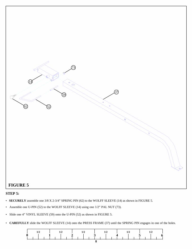
STEP 5:
8
0 1 2 3 4 5 61/2 1/2 1/2 1/2 1/2 1/2
• SECURELY assemble one 3/8 X 2-3/4” SPRING PIN (62) to the WOLFF SLEEVE (14) as shown in FIGURE 5.
FIGURE 5
• Assemble one U-PIN (52) to the WOLFF SLEEVE (14) using one 1/2” PAL NUT (73).
• Slide one 4” VINYL SLEEVE (59) onto the U-PIN (52) as shown in FIGURE 5.
• CAREFULLY slide the WOLFF SLEEVE (14) onto the PRESS FRAME (37) until the SPRING PIN engages in one of the holes.
14
37
73
59
5262
9
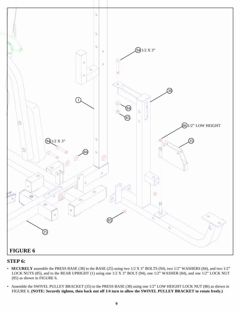
STEP 6:
FIGURE 6
• SECURELY assemble the PRESS BASE (38) to the BASE (25) using two 1/2 X 3” BOLTS (94), two 1/2” WASHERS (84), and two 1/2”LOCK NUTS (85), and to the REAR UPRIGHT (1) using one 1/2 X 3” BOLT (94), one 1/2” WASHER (84), and one 1/2” LOCK NUT(85) as shown in FIGURE 6.
• Assemble the SWIVEL PULLEY BRACKET (35) to the PRESS BASE (38) using one 1/2” LOW HEIGHT LOCK NUT (86) as shown inFIGURE 6. (NOTE: Securely tighten, then back nut off 1/4 turn to allow the SWIVEL PULLEY BRACKET to rotate freely.)
84
85
84
94 1/2 X 3”
94 1/2 X 3”
86 1/2” LOW HEIGHT
38
25
85
35
1
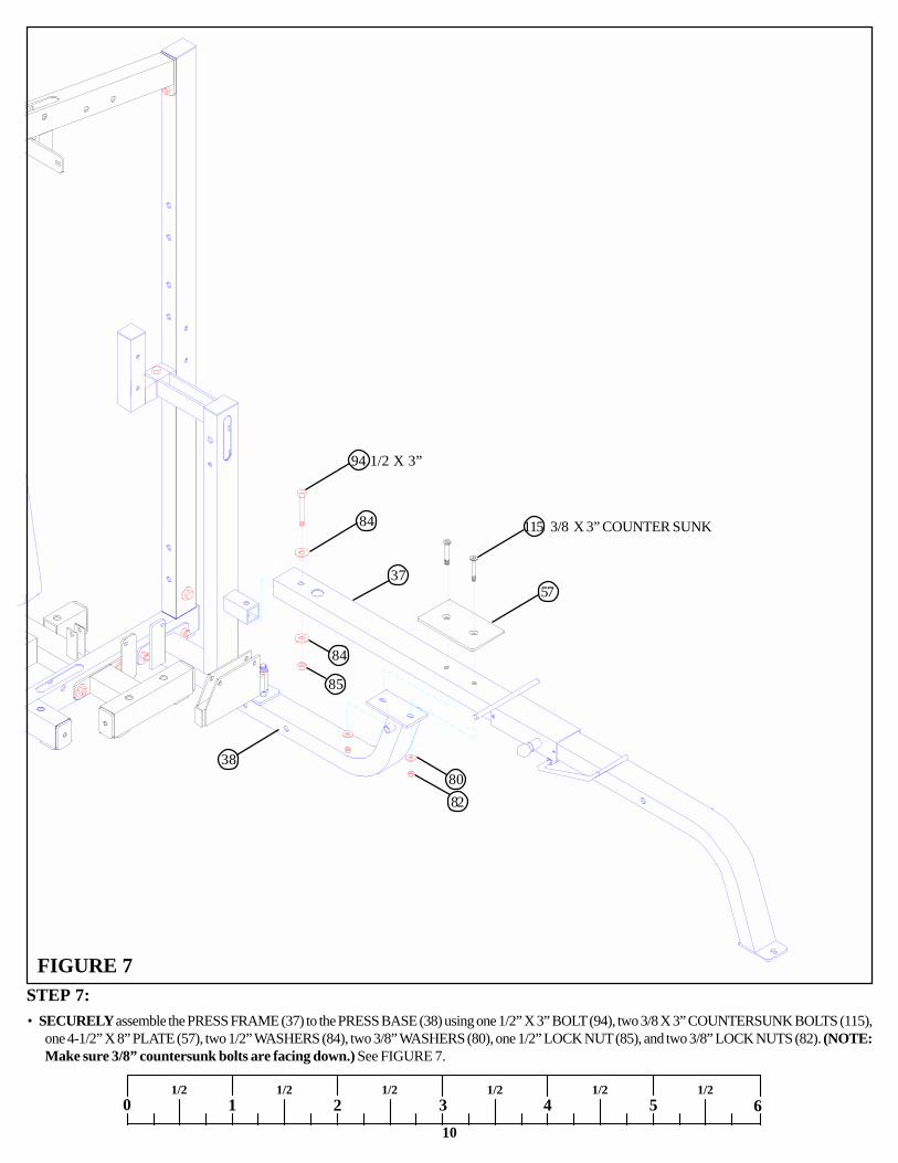
STEP 7:FIGURE 7
10
• SECURELY assemble the PRESS FRAME (37) to the PRESS BASE (38) using one 1/2” X 3” BOLT (94), two 3/8 X 3” COUNTERSUNK BOLTS (115),one 4-1/2” X 8” PLATE (57), two 1/2” WASHERS (84), two 3/8” WASHERS (80), one 1/2” LOCK NUT (85), and two 3/8” LOCK NUTS (82). (NOTE:Make sure 3/8” countersunk bolts are facing down.) See FIGURE 7.
0 1 2 3 4 5 61/2 1/2 1/2 1/2 1/2 1/2
115 3/8 X 3” COUNTER SUNK
82
94 1/2 X 3”
84
85
8038
5737
84
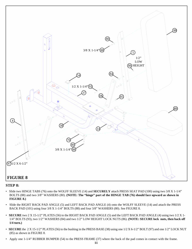
STEP 8:
FIGURE 8
11
• Slide two HINGE TABS (76) onto the WOLFF SLEEVE (14) and SECURELY attach PRESS SEAT PAD (100) using two 3/8 X 1-1/4”BOLTS (88) and two 3/8” WASHERS (80). (NOTE: The “hinge” part of the HINGE TAB (76) should face upward as shown inFIGURE 8.)
• Slide the RIGHT BACK PAD ANGLE (5) and LEFT BACK PAD ANGLE (4) onto the WOLFF SLEEVE (14) and attach the PRESSBACK PAD (101) using four 3/8 X 1-1/4” BOLTS (88) and four 3/8” WASHERS (80). See FIGURE 8.
• SECURE two 2 X 15-1/2” PLATES (56) to the RIGHT BACK PAD ANGLE (5) and the LEFT BACK PAD ANGLE (4) using two 1/2 X 1-1/4” BOLTS (93), two 1/2” WASHERS (84) and two 1/2” LOW HEIGHT LOCK NUTS (86). (NOTE: SECURE lock nuts, then back off1/4 turn.)
• SECURE the 2 X 15-1/2” PLATES (56) to the bushing in the PRESS BASE (38) using one 1/2 X 6-1/2” BOLT (97) and one 1/2” LOCK NUT(85) as shown in FIGURE 8.
• Apply one 1-1/4” RUBBER BUMPER (54) to the PRESS FRAME (37) where the back of the pad comes in contact with the frame.
4
5
80
54
3785
100
14
7680
84
1/2 X 1-1/4” 93
3/8 X 1-1/4” 88
116
86
101
3/8 X 1-1/4” 88
1/2”LOW
HEIGHT
38
97 1/2 X 6-1/2”

12
STEP 9:
FIGURE 9
• LOOSELY assemble the PRESS ARM ADJUST (36) to the REAR UPRIGHT (1) using two 1” PILLOW BLOCK BEARINGS (49), four3/8 X 3-1/4” BOLTS (91), four 3/8” WASHERS (80), and four 3/8” LOCK NUTS (82). (NOTE: Assemble PILLOW BLOCKS (49) so theset screws are on the outside, this will allow more adjustment.) See FIGURE 9.
• Apply two NON-SKID STRIPS (61) to the CALF/LOW ROW (9) as shown in FIGURE 9.
• SECURELY assemble CALF/LOW ROW (9) to the PRESS BASE (38) using two 1/2 X 4” BOLTS (96), two 1/2” WASHERS (84), and two1/2” LOCK NUTS (85) as shown in FIGURE 9.
0 1 2 3 4 5 61/2 1/2 1/2 1/2 1/2 1/2
• Adjust the PILLOW BLOCK BEARINGS (49) until the PRESS ARM ADJUST (36) is level, then SECURELY tighten bolts.
• Center PRESS ARM ADJUST (36) to line up with the post on the PRESS BASE (38) and securely tighten set screws on the PILLOW BLOCKBEARINGS (49). See FIGURE 9.
84
85
38
9
61
3682
49
1
80
96 1/2 X 4”
91 3/8 X 3-1/4”
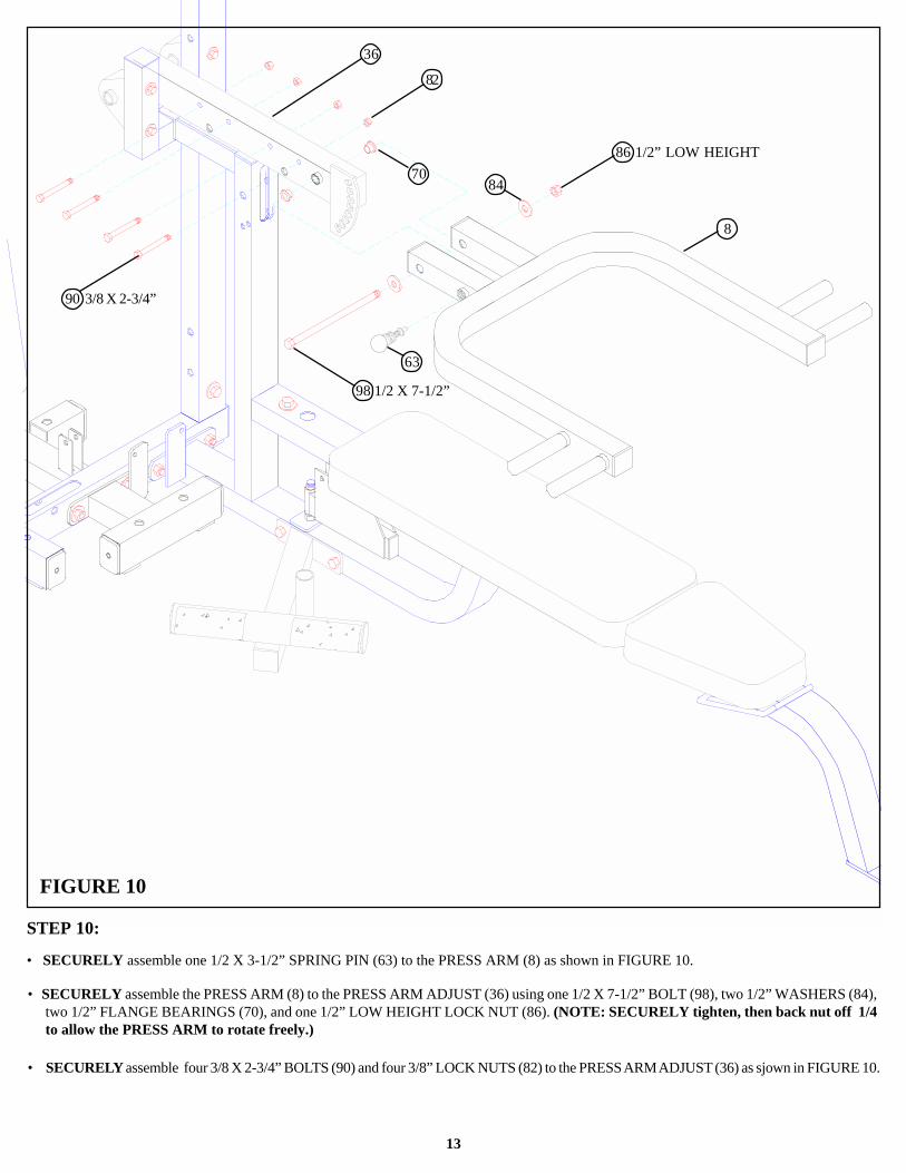
STEP 10:
13
• SECURELY assemble one 1/2 X 3-1/2” SPRING PIN (63) to the PRESS ARM (8) as shown in FIGURE 10.
FIGURE 10
• SECURELY assemble the PRESS ARM (8) to the PRESS ARM ADJUST (36) using one 1/2 X 7-1/2” BOLT (98), two 1/2” WASHERS (84),two 1/2” FLANGE BEARINGS (70), and one 1/2” LOW HEIGHT LOCK NUT (86). (NOTE: SECURELY tighten, then back nut off 1/4to allow the PRESS ARM to rotate freely.)
63
8
70
36
86 1/2” LOW HEIGHT
98 1/2 X 7-1/2”
84
82
90 3/8 X 2-3/4”
• SECURELY assemble four 3/8 X 2-3/4” BOLTS (90) and four 3/8” LOCK NUTS (82) to the PRESS ARM ADJUST (36) as sjown in FIGURE 10.

STEP 11:
FIGURE 11
14
• SECURELY assemble the REAR BASE LEG (31) to the LEG FRAME (34) using two 1/2 X 3” BOLTS (94), two 1/2” WASHERS (84), andtwo 1/2” LOCK NUTS (85) as shown in FIGURE 11.
0 1 2 3 4 5 61/2 1/2 1/2 1/2 1/2 1/2
STEP 12:
FIGURE 12
• SECURELY assemble the LEFT & RIGHT LEG EXTENSION HANDLES (16 & 15) to the LEG FRAME (34) using two 3/8 X 3-1/4”BOLTS (91), four 3/8” WASHERS (80), and two 3/8” LOCK NUTS (82). See FIGURE 12.
• Slide two HINGE TABS (76) onto the LEG FRAME (34) as shown in FIGURE 12. (NOTE: The “hinge” part of the HINGE TAB shouldface downward.)
8586
31
34
94 1/2 X 3”
95 3/8 X 3-1/4”
15
76
34
7616
8082
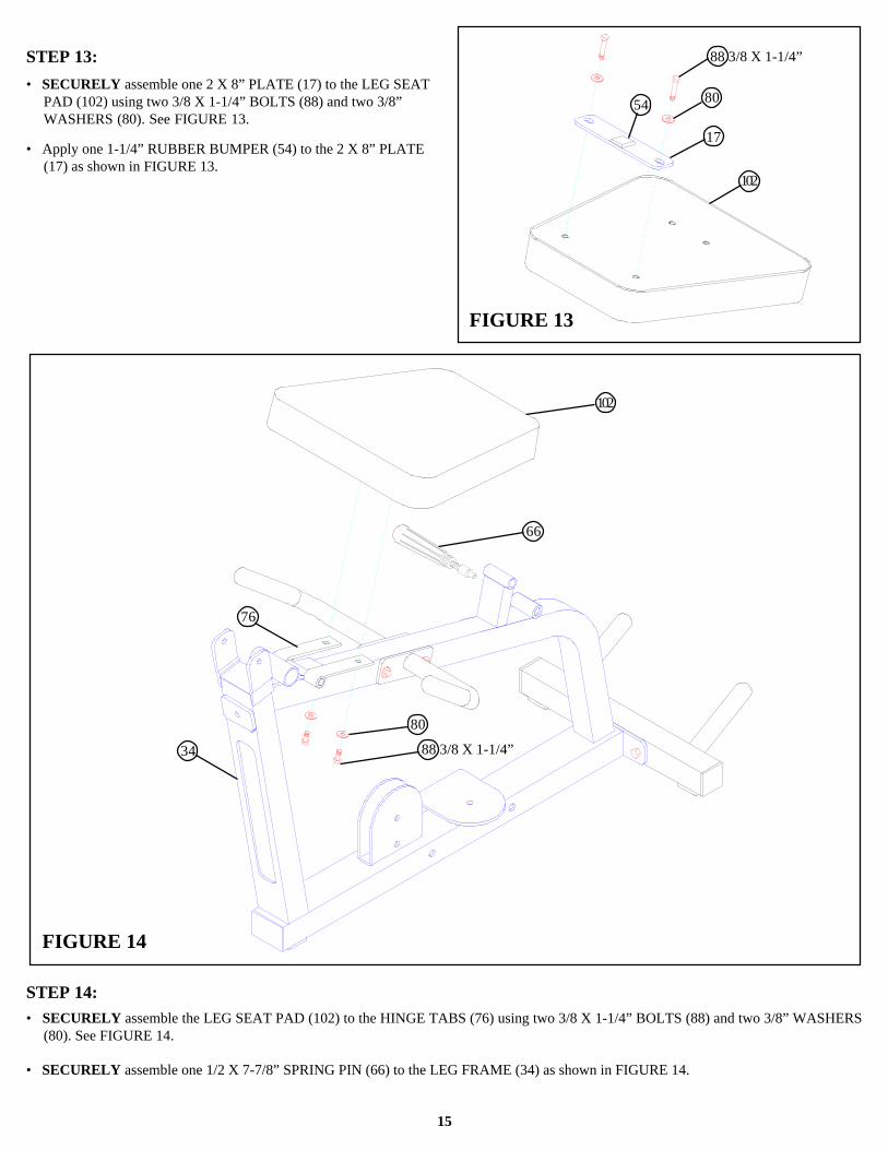
STEP 13:
FIGURE 13
15
• SECURELY assemble one 2 X 8” PLATE (17) to the LEG SEATPAD (102) using two 3/8 X 1-1/4” BOLTS (88) and two 3/8”WASHERS (80). See FIGURE 13.
STEP 14:• SECURELY assemble the LEG SEAT PAD (102) to the HINGE TABS (76) using two 3/8 X 1-1/4” BOLTS (88) and two 3/8” WASHERS
(80). See FIGURE 14.
FIGURE 14
80
17
102
88 3/8 X 1-1/4”
54
• Apply one 1-1/4” RUBBER BUMPER (54) to the 2 X 8” PLATE(17) as shown in FIGURE 13.
• SECURELY assemble one 1/2 X 7-7/8” SPRING PIN (66) to the LEG FRAME (34) as shown in FIGURE 14.
88 3/8 X 1-1/4”
76
34
66
102
80
16
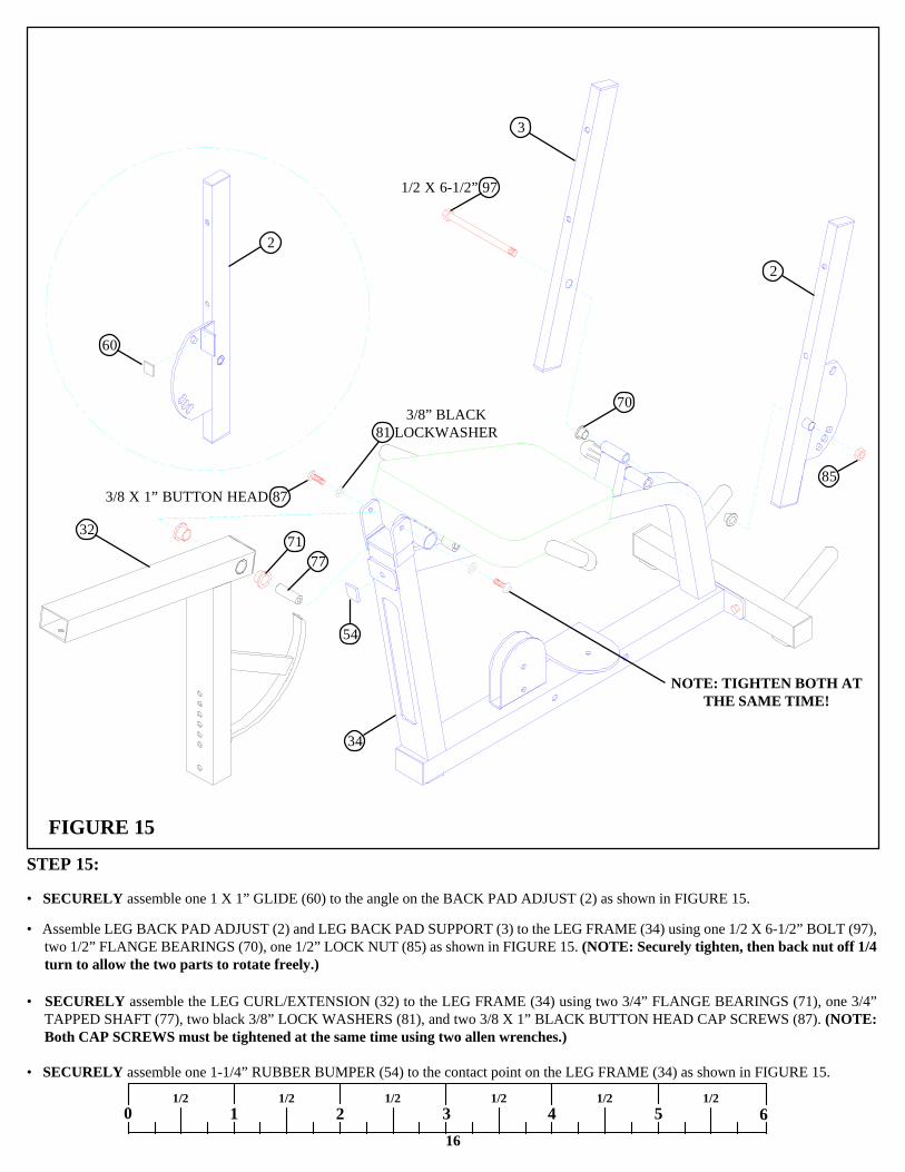
STEP 15:
FIGURE 15
• Assemble LEG BACK PAD ADJUST (2) and LEG BACK PAD SUPPORT (3) to the LEG FRAME (34) using one 1/2 X 6-1/2” BOLT (97),two 1/2” FLANGE BEARINGS (70), one 1/2” LOCK NUT (85) as shown in FIGURE 15. (NOTE: Securely tighten, then back nut off 1/4turn to allow the two parts to rotate freely.)
0 1 2 3 4 5 61/2 1/2 1/2 1/2 1/2 1/2
• SECURELY assemble the LEG CURL/EXTENSION (32) to the LEG FRAME (34) using two 3/4” FLANGE BEARINGS (71), one 3/4”TAPPED SHAFT (77), two black 3/8” LOCK WASHERS (81), and two 3/8 X 1” BLACK BUTTON HEAD CAP SCREWS (87). (NOTE:Both CAP SCREWS must be tightened at the same time using two allen wrenches.)
3/8 X 1” BUTTON HEAD 87
1/2 X 6-1/2” 97
71
34
77
54
32
2
3
85
70
• SECURELY assemble one 1-1/4” RUBBER BUMPER (54) to the contact point on the LEG FRAME (34) as shown in FIGURE 15.
3/8” BLACK81 LOCKWASHER
2
60
• SECURELY assemble one 1 X 1” GLIDE (60) to the angle on the BACK PAD ADJUST (2) as shown in FIGURE 15.
NOTE: TIGHTEN BOTH ATTHE SAME TIME!

STEP 16:
17
FIGURE 16
• SECURELY assemble the LEG BACK PAD (103) to the LEG BACK PAD ADJUST (2) and the LEG BACK PAD SUPPORT (3) usingfour 3/8 X 3-1/4” BOLTS (91) and four 3/8” WASHERS (80). See FIGURE 16.
• SECURELY assemble two 4 X 7” ROLLER PADS (41) to the LEG FRAME (34) using one 19-1/4” TUBE (39) and two 1-5/16” SHAFTCOLLARS (79). SECURELY tighten set screws on SHAFT COLLARS (79). See FIGURE 16.
3
2
34
7941
39
103
80
3/8 X 3-1/4” 91
18
0 1 2 3 4 5 61/2 1/2 1/2 1/2 1/2 1/2
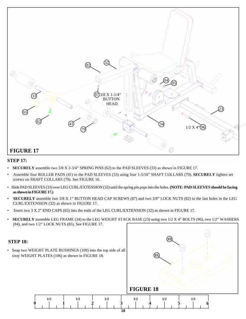
STEP 17:
FIGURE 17
• SECURELY assemble two 3/8 X 2-3/4” SPRING PINS (62) to the PAD SLEEVES (33) as shown in FIGURE 17.
• Assemble four ROLLER PADS (41) to the PAD SLEEVES (33) using four 1-5/16” SHAFT COLLARS (79). SECURELY tighten setscrews on SHAFT COLLARS (79). See FIGURE 16.
• Slide PAD SLEEVES (33) over LEG CURL/EXTENSION (32) until the spring pin pops into the holes. (NOTE: PAD SLEEVES should be facingas shown in FIGURE 17.)
• Insert two 3 X 2” END CAPS (65) into the ends of the LEG CURL/EXTENSION (32) as shown in FIGURE 17.
• SECURELY assemble two 3/8 X 1” BUTTON HEAD CAP SCREWS (87) and two 3/8” LOCK NUTS (82) to the last holes in the LEGCURL/EXTENSION (32) as shown in FIGURE 17.
• SECURELY assemble LEG FRAME (34) to the LEG WEIGHT STACK BASE (23) using two 1/2 X 4” BOLTS (96), two 1/2” WASHERS(84), and two 1/2” LOCK NUTS (85). See FIGURE 17.
8584
23
79
62 41
33
65
82 32
1/2 X 4” 96
87 3/8 X 1-1/4”BUTTON
HEAD
STEP 18:
FIGURE 18
109
106• Snap two WEIGHT PLATE BUSHINGS (109) into the top side of all
sixty WEIGHT PLATES (106) as shown in FIGURE 18.
34
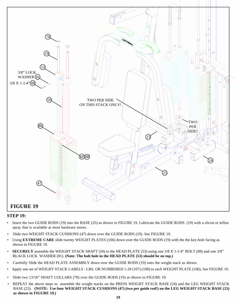
STEP 19:
19
FIGURE 19
• Insert the two GUIDE RODS (19) into the BASE (25) as shown in FIGURE 19. Lubricate the GUIDE RODS (19) with a slicon or teflonspray that is available at most hardware stores.
• Slide two WEIGHT STACK CUSHIONS (47) down over the GUIDE RODS (19). See FIGURE 19.• Using EXTREME CARE slide twenty WEIGHT PLATES (106) down over the GUIDE RODS (19) with the the key-hole facing as
shown in FIGURE 19.
• SECURELY assemble the WEIGHT STACK SHAFT (50) to the HEAD PLATE (53) using one 3/8 X 1-1/4” BOLT (88) and one 3/8”BLACK LOCK WASHER (81). (Note: The bolt hole in the HEAD PLATE (53) should be on top.)
• Carefully Slide the HEAD PLATE ASSEMBLY down over the GUIDE RODS (19) onto the weight stack as shown.
• Slide two 13/16” SHAFT COLLARS (78) over the GUIDE RODS (19) as shown in FIGURE 19.
• REPEAT the above steps to assemble the weight stacks on the PRESS WEIGHT STACK BASE (24) and the LEG WEIGHT STACKBASE (23). (NOTE: Use four WEIGHT STACK CUSHIONS (47) (two per guide rod!) on the LEG WEIGHT STACK BASE (23)as shown in FIGURE 19.)
TWOPER
SIDE!
108107
106
50
3/8” LOCKWASHER 81
53
19
78
3/8 X 1-1/4” 88
24
23
25
47
• Apply one set of WEIGHT STACK LABELS - LBS. OR NUMBERED 1-20 (107) (108) to each WEIGHT PLATE (106). See FIGURE 19.
TWO PER SIDEON THIS STACK ONLY!
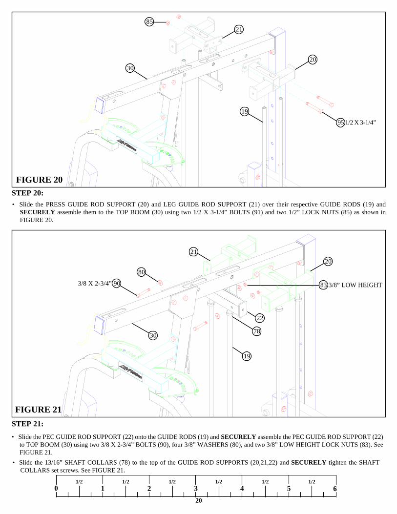
STEP 20:FIGURE 20
20
• Slide the PRESS GUIDE ROD SUPPORT (20) and LEG GUIDE ROD SUPPORT (21) over their respective GUIDE RODS (19) andSECURELY assemble them to the TOP BOOM (30) using two 1/2 X 3-1/4” BOLTS (91) and two 1/2” LOCK NUTS (85) as shown inFIGURE 20.
0 1 2 3 4 5 61/2 1/2 1/2 1/2 1/2 1/2
STEP 21:
FIGURE 21
• Slide the 13/16” SHAFT COLLARS (78) to the top of the GUIDE ROD SUPPORTS (20,21,22) and SECURELY tighten the SHAFTCOLLARS set screws. See FIGURE 21.
• Slide the PEC GUIDE ROD SUPPORT (22) onto the GUIDE RODS (19) and SECURELY assemble the PEC GUIDE ROD SUPPORT (22)to TOP BOOM (30) using two 3/8 X 2-3/4” BOLTS (90), four 3/8” WASHERS (80), and two 3/8” LOW HEIGHT LOCK NUTS (83). SeeFIGURE 21.
3/8 X 2-3/4” 90
95 1/2 X 3-1/4”
83 3/8” LOW HEIGHT
22
78
19
20
80
2185
21
20
19
30
30
21
46
44
45
42
43
22
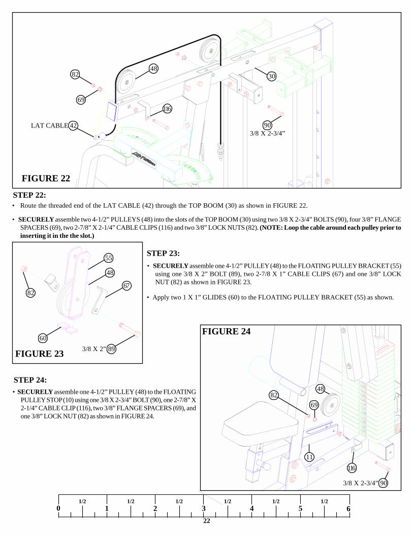
STEP 22:
FIGURE 22
• SECURELY assemble two 4-1/2” PULLEYS (48) into the slots of the TOP BOOM (30) using two 3/8 X 2-3/4” BOLTS (90), four 3/8” FLANGESPACERS (69), two 2-7/8” X 2-1/4” CABLE CLIPS (116) and two 3/8” LOCK NUTS (82). (NOTE: Loop the cable around each pulley prior toinserting it in the the slot.)
0 1 2 3 4 5 61/2 1/2 1/2 1/2 1/2 1/2
• SECURELY assemble one 4-1/2” PULLEY (48) to the FLOATINGPULLEY STOP (10) using one 3/8 X 2-3/4” BOLT (90), one 2-7/8” X2-1/4” CABLE CLIP (116), two 3/8” FLANGE SPACERS (69), andone 3/8” LOCK NUT (82) as shown in FIGURE 24.
FIGURE 23
FIGURE 24
STEP 23:• SECURELY assemble one 4-1/2” PULLEY (48) to the FLOATING PULLEY BRACKET (55)
using one 3/8 X 2” BOLT (89), two 2-7/8 X 1” CABLE CLIPS (67) and one 3/8” LOCKNUT (82) as shown in FIGURE 23.
STEP 24:
• Route the threaded end of the LAT CABLE (42) through the TOP BOOM (30) as shown in FIGURE 22.
3/8 X 2” 89
82
60
48
55
• Apply two 1 X 1” GLIDES (60) to the FLOATING PULLEY BRACKET (55) as shown.
82
LAT CABLE 42
4882
48
11
69
903/8 X 2-3/4”
3/8 X 2-3/4” 90
30
69
116
67
116

23
STEP 26:
STEP 25:
FIGURE 25
• Route the LAT CABLE (42) around the pulley in FLOATING PULLEY STOP (11) and the FLOATING PULLEY BRACKET (55) as shown inFIGURE 25. (NOTE: The CABLE CLIPS may need to be loosened.)
• SECURELY assemble two 4-1/2” PULLEYS (48) into the slots of the BASE (25) using two 3/8 X 2-3/4” BOLTS (90), four 3/8” FLANGESPACERS (69), and two 3/8” LOCK NUTS (82). (NOTE: Loop the cable around each pulley prior to inserting it in the the slot.)
• SECURELY assemble one 4-1/2” PULLEY (48) into the rear slot of the TOP BOOM (30) using one 3/8 X 2-3/4” BOLT (90), two 3/8” FLANGESPACERS (69), one 2-7/8” X 2-1/4” CABLE CLIP (116) and one 3/8” LOCK NUT (82). (NOTE: Loop the cable around the pulley prior to insertingit in the the slot.)
• Route the threaded end of the LAT CABLE (42) through the TOP BOOM (30) and down through the PEC GUIDE ROD SUPPORT (22) asshown in FIGURE 26.
FIGURE 26
90 3/8 X 2-3/4”
42LAT
CABLE
55
11
69
82
90 3/8 X 2-3/4”
LAT CABLE 42 30
69
48
82
48
25
116
24
0 1 2 3 4 5 61/2 1/2 1/2 1/2 1/2 1/2
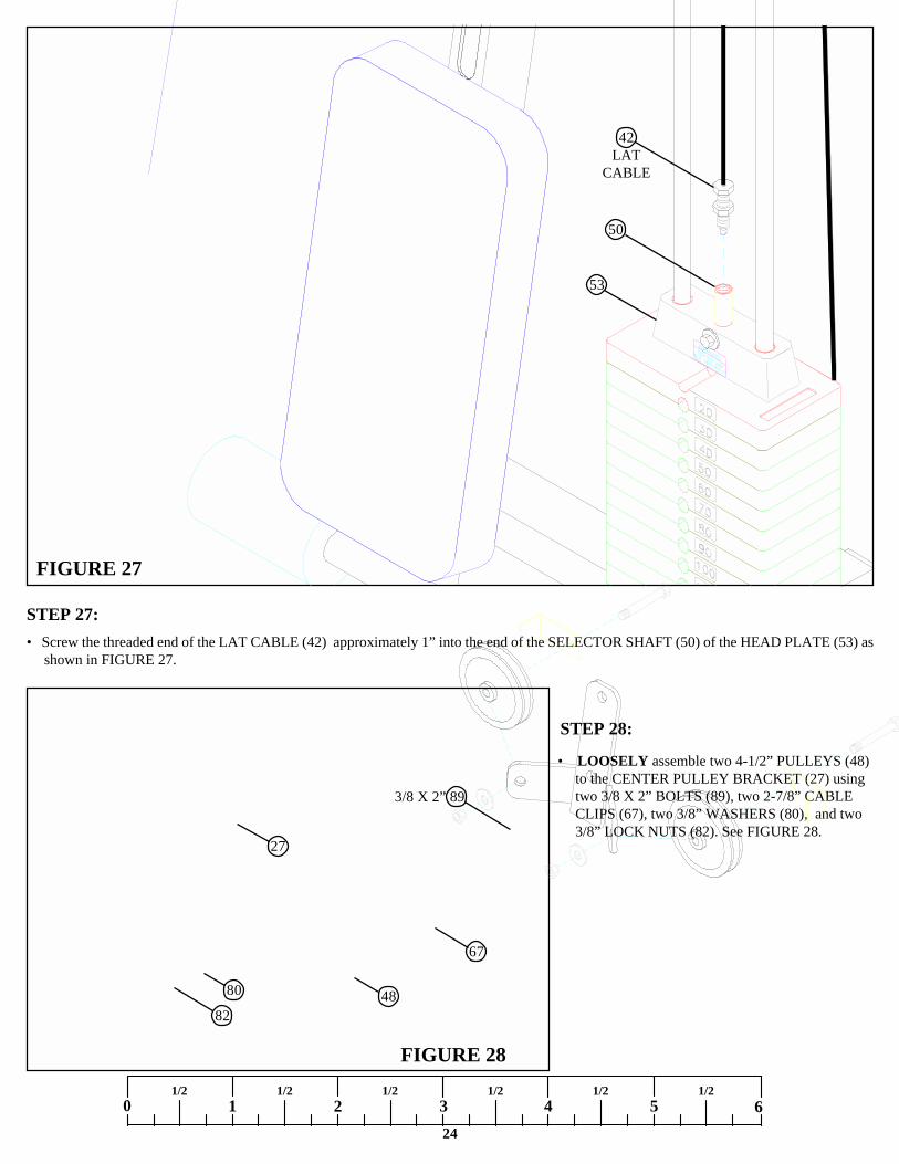
STEP 27:
FIGURE 27
FIGURE 28
STEP 28:
• LOOSELY assemble two 4-1/2” PULLEYS (48)to the CENTER PULLEY BRACKET (27) usingtwo 3/8 X 2” BOLTS (89), two 2-7/8” CABLECLIPS (67), two 3/8” WASHERS (80), and two3/8” LOCK NUTS (82). See FIGURE 28.
• Screw the threaded end of the LAT CABLE (42) approximately 1” into the end of the SELECTOR SHAFT (50) of the HEAD PLATE (53) asshown in FIGURE 27.
3/8 X 2” 89
67
4880
82
27
53
50
42LAT
CABLE
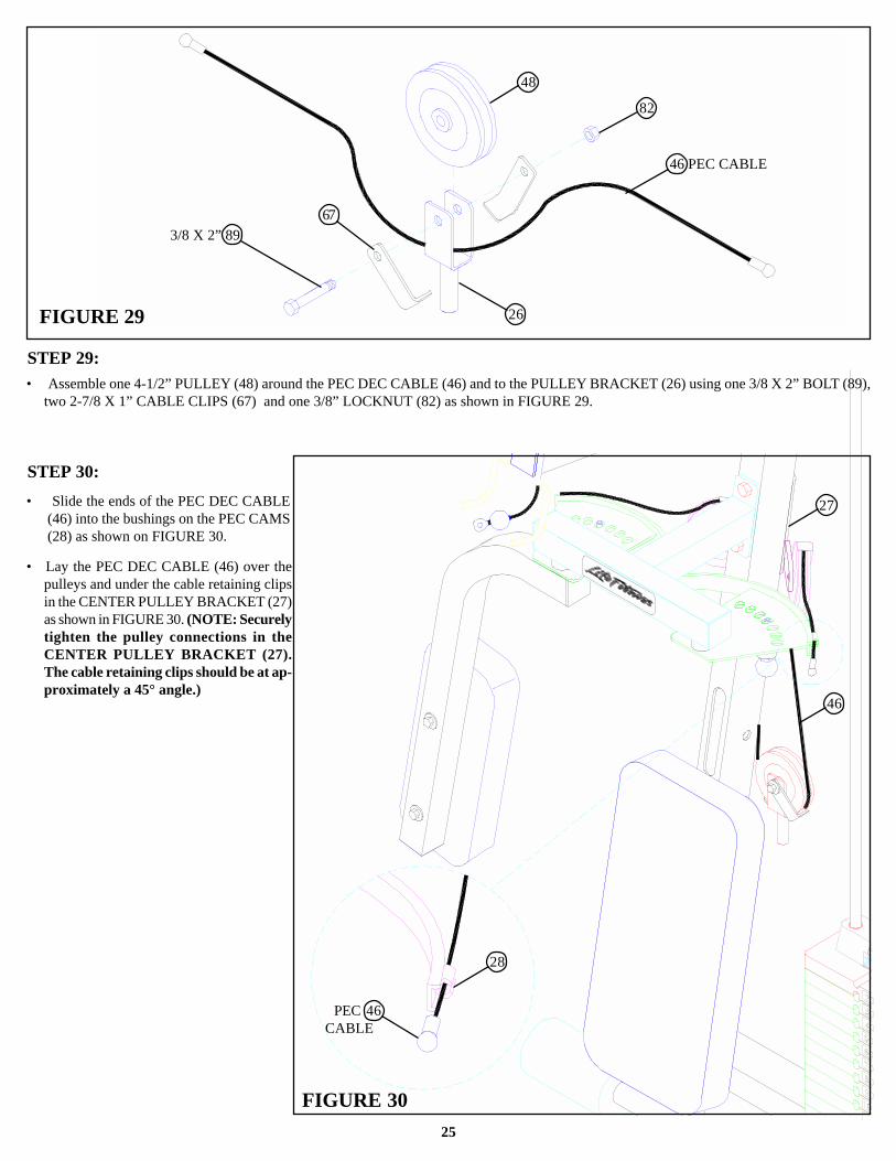
STEP 29:
25
FIGURE 29
• Assemble one 4-1/2” PULLEY (48) around the PEC DEC CABLE (46) and to the PULLEY BRACKET (26) using one 3/8 X 2” BOLT (89),two 2-7/8 X 1” CABLE CLIPS (67) and one 3/8” LOCKNUT (82) as shown in FIGURE 29.
STEP 30:
FIGURE 30
3/8 X 2” 89
48
46 PEC CABLE
82
• Slide the ends of the PEC DEC CABLE(46) into the bushings on the PEC CAMS(28) as shown on FIGURE 30.
• Lay the PEC DEC CABLE (46) over thepulleys and under the cable retaining clipsin the CENTER PULLEY BRACKET (27)as shown in FIGURE 30. (NOTE: Securelytighten the pulley connections in theCENTER PULLEY BRACKET (27).The cable retaining clips should be at ap-proximately a 45° angle.)
46
46
28
27
PEC CABLE
26
67
26
0 1 2 3 4 5 61/2 1/2 1/2 1/2 1/2 1/2
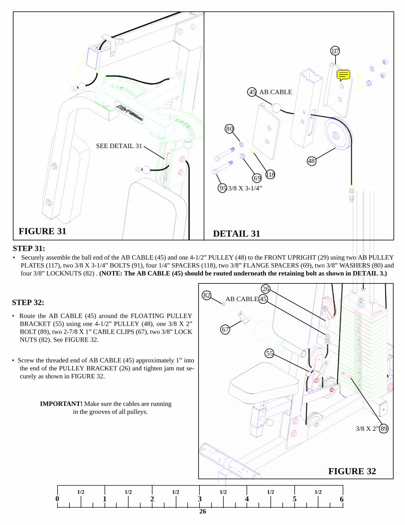
STEP 32:
FIGURE 32
• Screw the threaded end of AB CABLE (45) approximately 1” intothe end of the PULLEY BRACKET (26) and tighten jam nut se-curely as shown in FIGURE 32.
IMPORTANT! Make sure the cables are runningin the grooves of all pulleys.
3/8 X 2” 89
82 AB CABLE 4526
• Route the AB CABLE (45) around the FLOATING PULLEYBRACKET (55) using one 4-1/2” PULLEY (48), one 3/8 X 2”BOLT (89), two 2-7/8 X 1” CABLE CLIPS (67), two 3/8” LOCKNUTS (82). See FIGURE 32.
55
67
STEP 31:
FIGURE 31 DETAIL 31
45 AB CABLE
95 3/8 X 3-1/4”
117
SEE DETAIL 31
• Securely assemble the ball end of the AB CABLE (45) and one 4-1/2” PULLEY (48) to the FRONT UPRIGHT (29) using two AB PULLEYPLATES (117), two 3/8 X 3-1/4” BOLTS (91), four 1/4” SPACERS (118), two 3/8” FLANGE SPACERS (69), two 3/8” WASHERS (80) andfour 3/8” LOCKNUTS (82) . (NOTE: The AB CABLE (45) should be routed underneath the retaining bolt as shown in DETAIL 3.)
118
48
69
80
sullivt
Note
6954703 - WLDMT AB PULLEY PLATE WHT

27
STEP 33:
FIGURE 33
• SECURE the ball end of the PRESS CABLE (44) and two 4-1/2” PULLEYS (48) to the SWIVEL PULLEY BRACKET (35) using two 3/8X 2” BOLTS (89), four 3/8” WASHERS (80), and two 3/8” LOCK NUTS (82) as shown in FIGURE 33. (NOTE: Loop the cable aroundthe pulleys prior to inserting it into the SWIVEL PULLEY BRACKET.)
• Route the threaded end of the PRESS CABLE (44) through the large hole in the PRESS FRAME (37) as shown in FIGURE 33.
89 3/8 X 2”
48
8082
35
37
44
44 PRESS CABLE
28
0 1 2 3 4 5 61/2 1/2 1/2 1/2 1/2 1/2
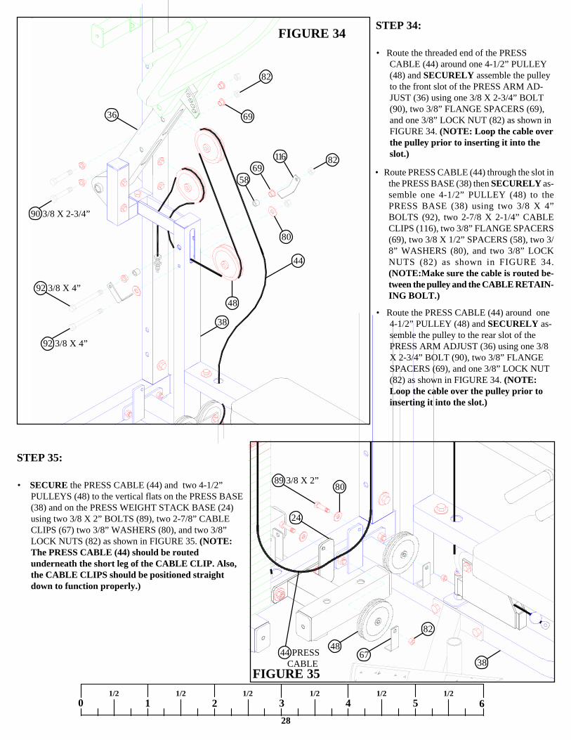
STEP 34:FIGURE 34• Route the threaded end of the PRESS
CABLE (44) around one 4-1/2” PULLEY(48) and SECURELY assemble the pulleyto the front slot of the PRESS ARM AD-JUST (36) using one 3/8 X 2-3/4” BOLT(90), two 3/8” FLANGE SPACERS (69),and one 3/8” LOCK NUT (82) as shown inFIGURE 34. (NOTE: Loop the cable overthe pulley prior to inserting it into theslot.)
• Route PRESS CABLE (44) through the slot inthe PRESS BASE (38) then SECURELY as-semble one 4-1/2” PULLEY (48) to thePRESS BASE (38) using two 3/8 X 4”BOLTS (92), two 2-7/8 X 2-1/4” CABLECLIPS (116), two 3/8” FLANGE SPACERS(69), two 3/8 X 1/2” SPACERS (58), two 3/8” WASHERS (80), and two 3/8” LOCKNUTS (82) as shown in FIGURE 34.(NOTE:Make sure the cable is routed be-tween the pulley and the CABLE RETAIN-ING BOLT.)
• Route the PRESS CABLE (44) around one4-1/2” PULLEY (48) and SECURELY as-semble the pulley to the rear slot of thePRESS ARM ADJUST (36) using one 3/8X 2-3/4” BOLT (90), two 3/8” FLANGESPACERS (69), and one 3/8” LOCK NUT(82) as shown in FIGURE 34. (NOTE:Loop the cable over the pulley prior toinserting it into the slot.)
82
69
6958
82
48
38
44
36
90 3/8 X 2-3/4”
92 3/8 X 4”
6738
48
82
44 PRESS CABLE
8089 3/8 X 2”
FIGURE 35
24
STEP 35:
• SECURE the PRESS CABLE (44) and two 4-1/2”PULLEYS (48) to the vertical flats on the PRESS BASE(38) and on the PRESS WEIGHT STACK BASE (24)using two 3/8 X 2” BOLTS (89), two 2-7/8” CABLECLIPS (67) two 3/8” WASHERS (80), and two 3/8”LOCK NUTS (82) as shown in FIGURE 35. (NOTE:The PRESS CABLE (44) should be routedunderneath the short leg of the CABLE CLIP. Also,the CABLE CLIPS should be positioned straightdown to function properly.)
92 3/8 X 4”
80
116

STEP 36:
29
FIGURE 36
• SECURE the PRESS CABLE (44) and one 4-1/2” PULLEY (48) to the PRESS GUIDE ROD SUPPORT (20) using one 3/8 X 2-3/4”BOLT (90), two 3/8” FLANGE SPACERS (69), one 2-7/8 X 2-1/4” CABLE CLIP (116) and one 3/8” LOCK NUT (82) as shown inFIGURE 36. (NOTE: Loop the cable around the pulleys prior to inserting it into the PRESS GUIDE ROD SUPPORT.)
3/8 X 2-3/4” 90
20
82
69
48
44 PRESS CABLE
STEP 37:
PRESS 44CABLE
50
53
• Screw the threaded end of the PRESS CABLE (44) approximately 1” into the end of the SELECTOR SHAFT (50) of the HEAD PLATE (53)as shown in FIGURE 37.
116
30
0 1 2 3 4 5 61/2 1/2 1/2 1/2 1/2 1/2
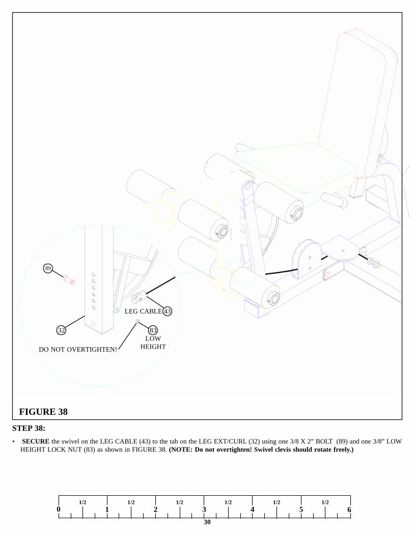
STEP 38:
FIGURE 38
• SECURE the swivel on the LEG CABLE (43) to the tab on the LEG EXT/CURL (32) using one 3/8 X 2” BOLT (89) and one 3/8” LOWHEIGHT LOCK NUT (83) as shown in FIGURE 38. (NOTE: Do not overtighten! Swivel clevis should rotate freely.)
89
LEG CABLE 43
32 83LOW
HEIGHTDO NOT OVERTIGHTEN!

31
FIGURE 39
IMPORTANT! Make sure the cables are runningin the grooves of all pulleys.
• SECURELY assemble one 4-1/2” PULLEY (48) to the horizontal bracket on the LEG FRAME (34) using one 3/8 X 2” BOLT (89), one3/8” WASHER (80), one 2-7/8” CABLE CLIP (67), and one 3/8” LOCK NUT (82) as shown in FIGURE 39. (NOTE: Before tightening,make sure CABLE CLIP (67) is positioned as shown in FIGURE 39.)
• SECURELY assemble one 4-1/2” PULLEY (48) to the vertical bracket on the LEG FRAME (34) using one 3/8 X 2” BOLT (89), two3/8” WASHERS (80), and one 3/8” LOCK NUT (82) as shown in FIGURE 39.
STEP 39:• Route the LEG CABLE (43) through the vertical and horizontal brackets on the LEG FRAME (34) as shown in FIGURE 39.
3/8 X 2” 89
43 LEG CABLE80
82
48
34
67
80
• SECURELY assemble one 3/8 X 2” BOLT (89), two 3/8” WASHERS (80), and one 3/8” LOCK NUT (82) to the vertical bracket as shown inFIGURE 39. (Make sure CABLE is running over 3/8 X 2” RETAINING BOLT.)

32
0 1 2 3 4 5 61/2 1/2 1/2 1/2 1/2 1/2
FIGURE 40
FIGURE 41
STEP 41:
STEP 40:• Route the threaded end of the LEG CABLE (43) under the leg weight stack and throught the vetical bracket on the LEG WEIGHT
STACK BASE (23) as shown in FIGURE 40.
3/8 X 2” 89
43 LEG CABLE48
23 82
80
• Assemble one 4-1/2” PULLEY to the vertical bracket on the WEIGHT STACK BASE (23) using one 3/8 X 2” BOLT (89),one 2-7/8 X 1”CABLE CLIP (67), two 3/8” WASHERS (80), and one 3/8” LOCK NUT (82) . (NOTE: Loop the cable under the pulley prior to inserting itinto the slot.)
• SECURE the LEG CABLE (43) and one 4-1/2” PULLEY (48) to the LEG GUIDE ROD SUPPORT (21) using one 3/8 X 2-3/4” BOLT(90), two 3/8” FLANGE SPACERS (69), one 2-7/8 X 2-1/4” CABLE CLIP (116)and one 3/8” LOCK NUT (82) as shown in FIGURE 41.(NOTE: Loop the cable around the pulleys prior to inserting it into the LEG GUIDE ROD SUPPORT.)
3/8 X 2-3/4” 90
LEG CABLE 43
48
82
69
21
67
116

STEP 42:
33
FIGURE 42
LEG CABLE 43
50
53
• Screw the threaded end of the LEG CABLE (43) approximately 1” into the end of the SELECTOR SHAFT (50) of the HEAD PLATE (53)as shown in FIGURE 42.
• Insert one WEIGHT STACK PIN (75) into each weight stack on the 8500GYM as shown in FIGURE 43.
FIGURE 43
• If upon completion of assembly, the HEAD PLATE (53) does not sit on topof the first WEIGHT PLATE (106), push the HEAD PLATE (53) down,insert the WEIGHT STACK PIN (75) and perform several repetitions at thepress station. This will relax the cable system and prevent the HEADPLATE (53) from lifting up.
• If after completing previous step, the HEAD PLATE (53) still does not siton top of the first WEIGHT PLATE (106) or if there is excess slack in thecable system, adjust the threaded end of the CABLE accordingly andretighten the jam nuts.
• If there is excess slack in the AB or PEC DEC cable system, adjust thethreaded end of the AB CABLE (45) accordingly and retighten the jamnut.
75
106
53STEP 43:• Perform the following to all three WEGHT STACKS:

STEP 44:
FIGURE 44
34
0 1 2 3 4 5 61/2 1/2 1/2 1/2 1/2 1/2
• SECURELY assemble the PRESS SHROUD (113-has press exercise placard ) to the PRESS GUIDE ROD SUPPORT (20) and the PRESSWEIGHT STACK BASE (24) using four 3/8” X 1” BOLTS (114) and four 3/8” WASHERS (80). See FIGURE 44.
• SECURELY assemble the PEC SHROUD (112-has warning label in right corner ) to the PEC GUIDE ROD SUPPORT (22) and the BASE(25) using using four 3/8” X 1” BOLTS (114) and four 3/8” WASHERS (80). See FIGURE 44.
113
114 3/8 X 1”
111
113
• SECURELY assemble the LEG SHROUD (111-has leg exercise placard ) to the LEG GUIDE ROD SUPPORT (21) and the LEG WEIGHTSTACK BASE (23) using four 3/8” X 1” BOLTS (114) and four 3/8” WASHERS (80). See FIGURE 44.
112
80
35
FIGURE 45
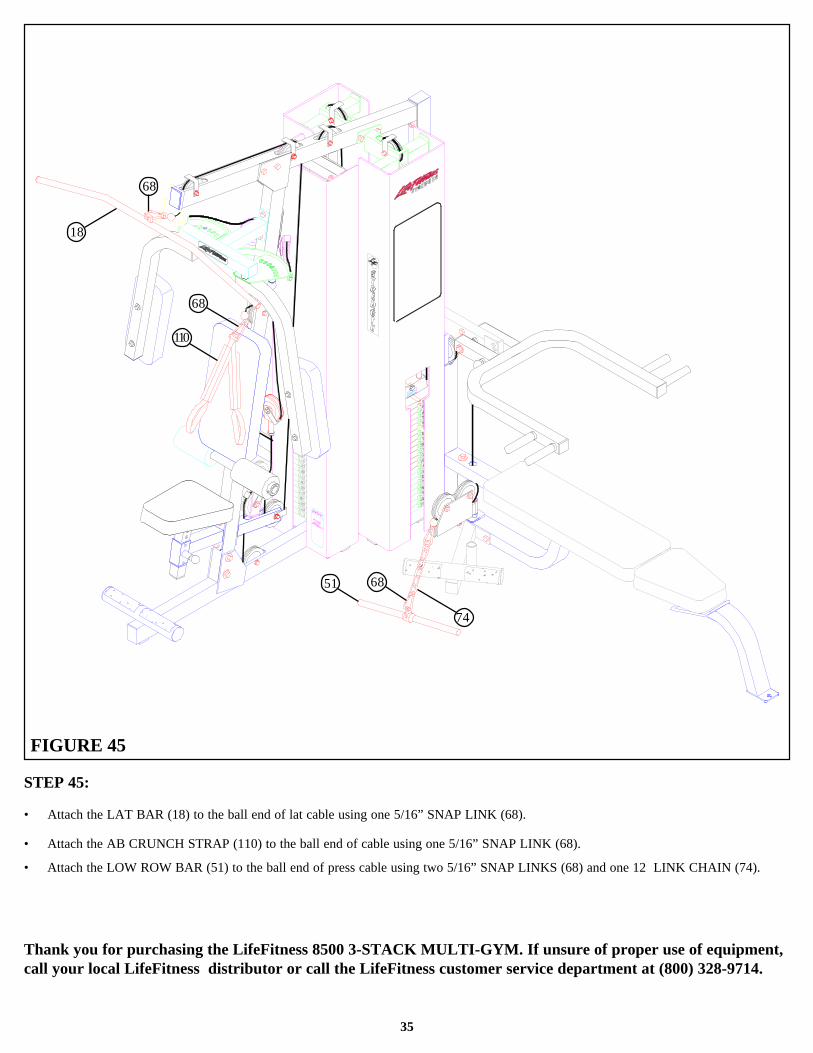
STEP 45:
• Attach the LAT BAR (18) to the ball end of lat cable using one 5/16” SNAP LINK (68).
• Attach the AB CRUNCH STRAP (110) to the ball end of cable using one 5/16” SNAP LINK (68).
• Attach the LOW ROW BAR (51) to the ball end of press cable using two 5/16” SNAP LINKS (68) and one 12 LINK CHAIN (74).
Thank you for purchasing the LifeFitness 8500 3-STACK MULTI-GYM. If unsure of proper use of equipment,call your local LifeFitness distributor or call the LifeFitness customer service department at (800) 328-9714.
74
6851
110
68
68
18