84 avenue Jean Jaurès CHAMPS-SUR-MARNE Fax :...
22
Centre Scientifique et Technique du Bâtiment 84 avenue Jean Jaurès CHAMPS-SUR-MARNE F-77447 Marne-la-Vallée Cedex 2 Tél. : (33) 01 64 68 82 82 Fax : (33) 01 60 05 70 37 Member of www.eota.eu European Technical Assessment ETA-10/0276 of 01/09/2015 English translation prepared by CSTB - Original version in French language General Part Nom commercial Trade name Spatec TM Plus Famille de produit Product family Cheville métallique en acier galvanisé à expansion par vissage à couple contrôlé, de fixation dans le béton: dimensions M6, M8, M10, M12, M16 et M20. Avec catégories de performances sismiques C1 et C2 : dimensions M10, M12, M16 Torque-controlled expansion anchor, made of galvanized steel, for use in concrete: sizes M6, M8, M10, M12 M16 et M20. With seismic performance categories C1 and C2: sizes M10, M12, M16. Titulaire Manufacturer ITW Australia (Ramset) 1 Ramset Drive Chirnside Park VIC 3116 Australia Usine de fabrication e Manufacturing plants Plant 1 Cette evaluation contient: This Assessment contains 22 pages incluant 17 annexes qui font partie intégrante de cette évaluation 22 pages including 17 annexes which form an integral part of this assessment Base de l‘ETE Basis of ETA ETAG 001, Version April 2013, utilisée en tant que EAD ETAG 001, Edition April 2013 used as EAD Cette evaluation remplace: This Assessment replaces ATE-10/0276 valide du 01/09/2011 au 01/09/2016 ETA-10/0276 with validity from 01/09/2011 to 01/09/2016 Translations of this European Technical Assessment in other languages shall fully correspond to the original issued document and should be identified as such. Communication of this European Technical Assessment, including transmission by electronic means, shall be in full. However, partial reproduction may be made, with the written consent of the issuing Technical Assessment Body. Any partial reproduction has to be identified as such.
Transcript of 84 avenue Jean Jaurès CHAMPS-SUR-MARNE Fax :...

Centre Scientifique et
Technique du Bâtiment 84 avenue Jean Jaurès CHAMPS-SUR-MARNE F-77447 Marne-la-Vallée Cedex 2 Tél. : (33) 01 64 68 82 82 Fax : (33) 01 60 05 70 37
Member of
www.eota.eu
European Technical Assessment
ETA-10/0276 of 01/09/2015
English translation prepared by CSTB - Original version in French language
General Part
Nom commercial Trade name
SpatecTM Plus
Famille de produit Product family
Cheville métallique en acier galvanisé à expansion par vissage à couple contrôlé, de fixation dans le béton: dimensions M6, M8, M10, M12, M16 et M20. Avec catégories de performances sismiques C1 et C2 : dimensions M10, M12, M16
Torque-controlled expansion anchor, made of galvanized steel, for use in concrete: sizes M6, M8, M10, M12 M16 et M20. With seismic performance categories C1 and C2: sizes M10, M12, M16.
Titulaire Manufacturer
ITW Australia (Ramset) 1 Ramset Drive Chirnside Park VIC 3116 Australia
Usine de fabrication e Manufacturing plants
Plant 1
Cette evaluation contient: This Assessment contains
22 pages incluant 17 annexes qui font partie intégrante de cette évaluation 22 pages including 17 annexes which form an integral part of this assessment
Base de l‘ETE Basis of ETA
ETAG 001, Version April 2013, utilisée en tant que EAD
ETAG 001, Edition April 2013 used as EAD
Cette evaluation remplace: This Assessment replaces
ATE-10/0276 valide du 01/09/2011 au 01/09/2016 ETA-10/0276 with validity from 01/09/2011 to 01/09/2016
Translations of this European Technical Assessment in other languages shall fully correspond to the original issued document and should be identified as such. Communication of this European Technical Assessment, including transmission by electronic means, shall be in full. However, partial reproduction may be made, with the written consent of the issuing Technical Assessment Body. Any partial reproduction has to be identified as such.

European technical assessment ETA-10/0276
English translation prepared by CSTB
Page 2 of 22 | 01/09/2015
Specific Part
1 Technical description of the product
The RAMSETTM
SpatecTM
Plus anchor is an anchor made of galvanized steel which is placed into a drilled hole and anchored by torque-controlled expansion.
The illustration and the description of the product are given in Annexes A.
2 Specification of the intended use
The performances given in Section 3 are only valid if the anchor is used in compliance with the specifications and conditions given in Annexes B.
The provisions made in this European technical assessment are based on an assumed working life of the anchor of 50 years. The indications given on the working life cannot be interpreted as a guarantee given by the producer, but are to be regarded only as a means for choosing the right products in relation to the expected economically reasonable working life of the works.
3 Performance of the product
3.1 Mechanical resistance and stability (BWR 1)
Essential characteristic Performance
Characteristic tension resistance acc. ETAG001, Annex C See Annex C 1
Characteristic shear resistance acc. ETAG001, Annex C See Annex C 2
Characteristic tension resistance acc. CEN/TS 1992-4 See Annex C 5
Characteristic shear resistance acc. CEN/TS 1992-4 See Annex C 6
Characteristic resistance under seismic action Cat 1 acc. TR045 See Annex C 11
Characteristic resistance under seismic action Cat 2 acc. TR045 See Annex C 12
Displacements See Annex C 13
3.2 Safety in case of fire (BWR 2)
Essential characteristic Performance
Reaction to fire Anchorages satisfy requirements for Class A1
Characteristic tension resistance under fire acc. ETAG001, Annex C See Annex C 3
Characteristic shear resistance under fire acc. ETAG001, Annex C See Annex C 4
Characteristic tension resistance under fire acc. CEN/TS 1992-4 See Annex C 7
Characteristic shear resistance under fire acc. CEN/TS 1992-4 See Annex C 8
3.3 Hygiene, health and the environment (BWR 3)
Regarding dangerous substances contained in this European technical approval, there may be requirements applicable to the products falling within its scope (e.g. transposed European legislation and national laws, regulations and administrative provisions). In order to meet the provisions of the Construction Products Directive, these requirements need also to be complied with, when and where they apply.

European technical assessment ETA-10/0276
English translation prepared by CSTB
Page 3 of 22 | 01/09/2015
3.4 Safety in use (BWR 4)
For Basic requirement Safety in use the same criteria are valid as for Basic Requirement Mechanical resistance and stability.
3.5 Protection against noise (BWR 5)
Not relevant.
3.6 Energy economy and heat retention (BWR 6)
Not relevant.
3.7 Sustainable use of natural resources (BWR 7)
For the sustainable use of natural resources no performance was determined for this product.
3.8 General aspects relating to fitness for use
Durability and Serviceability are only ensured if the specifications of intended use according to Annex B1 are kept.
4 Assessment and verification of constancy of performance (AVCP)
According to the Decision 96/582/EC of the European Commission1, as amended, the system of
assessment and verification of constancy of performance (see Annex V to Regulation (EU) No 305/2011) given in the following table apply.
Product Intended use Level or class
System
Metal anchors for use in concrete
For fixing and/or supporting to concrete, structural elements (which contributes to the stability of the works) or heavy units
― 1
5 Technical details necessary for the implementation of the AVCP system
Technical details necessary for the implementation of the Assessment and verification of constancy of performance (AVCP) system are laid down in the control plan deposited at Centre Scientifique et Technique du Bâtiment.
The manufacturer shall, on the basis of a contract, involve a notified body approved in the field of anchors for issuing the certificate of conformity CE based on the control plan.
The original French version is signed by
Charles Baloche
Technical Director
1 Official Journal of the European Communities L 254 of 08.10.1996

European technical assessment ETA-10/0276
English translation prepared by CSTB
Page 4 of 22 | 01/09/2015
RAMSETTM SpatecTM Plus expansion anchor
Product description
Parts, Materials
Annex A1
Assembled anchor:
1. cone
2. expansion sleeve
3. distance sleeve
4. washer
5. screw (or threaded rod with hexagonal nut or countersunk head)
Marking on the sleeve: S TRIGA Z
Table 1: Materials
Part Designation Material Protection
1 Cone 1.0765 steel
EN 10 087
Galvanised
5 m
2 Expansion sleeve 1.5530 steel
EN 10 149-2
Galvanised
5 m
3 Distance sleeve TS 37 a BK or S300Pb
NF A 49 341
Galvanised
5 m
4 Threaded rod 1. Steel Grade 8.8
EN 20 898-1
Galvanised
5 m
5 Screw Steel Grade 8.8
EN 20 898-1
Galvanised
5 m
6 Washer HLE S550MC Galvanised
5 m
7 Hexagonal nut Grade 8
EN 20 898-2
Galvanised
5 m
European technical assessment ETA-10/0276
English translation prepared by CSTB
Page 5 of 22 | 01/09/2015
RAMSETTM SpatecTM Plus expansion anchor
Product description
Parts, dimensions
Annex A2
Versions, parts and dimensions of the anchor :
Expansion sleeve Distance sleeve
Cone washer
Threaded rod (type E)
Screw (type V)
Countersunk head screw (type TF)
European technical assessment ETA-10/0276
English translation prepared by CSTB
Page 6 of 22 | 01/09/2015
RAMSETTM SpatecTM Plus expansion anchor
Product description
Parts, dimensions
Annex A2
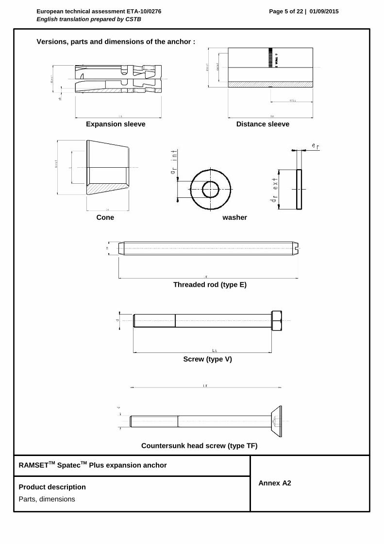
Table 2 : Dimensions
Dimensions of anchor bolt Spatec
TM Plus
References Rod Washer Distance sleeve
Expansion sleeve
Cone
Spatec Plus LE d Er drext drint Lm dmext dmint tfix Lb dbext eb Lc dc D
M6 V6-10/5 65
6 2 18 6,7
25
9,5 6,2
5
30 9,5 1,5 8 9,8 6 V6-10/20 80 40 20
E6-10/50 117 70 20
M8
V8-12/10 80
8 2 20 8,7
30
11,5 8,2
10
40 11,5 1,5 9,5 11,8 8
V8-12/20 90 40 20
V8-12/50 80 70 50
E8-12/20 99 40 20
E8-12/35 114 55 35
E8-12/55 134 75 55
E8-12/95 174 115 95
TF8-12/16 85 30 16
TF8-12/26 95 40 26
M1
0
V10-15/10 95
10 3 26 10,5
30
14,5 10,2
10
50 14,5 2 10,5 14,8 10
V10-15/20 105 40 20
V10-15/55 95 75 55
E10-15/20 114 40 20
E10-15/35 129 55 35
E10/15/55 149 75 55
E10-15/100 194 120 100
TF10-15/27 105 40 27
M1
2
V12-18/10 105
12 3 30 12,5
33
17,5 12,4
10
57 17,5 2,5 13 17,8 12
V12-18/25 120 48 25
V12-18/55 105 78 55
E12-18/25 132 48 25
E12-18/45 152 68 45
E12-18/65 172 88 65
E12-18/100 207 123 100
M1
6
V16-24/10 130
16 4 40 16,7
35
23 16,5
10
75 23,5 3,5 18,7 23,8 16
V16-24/25 145 50 25
V16-24/50 145 75 50
E16-24/25 159 50 25
E16-24/55 189 80 55
E16-24/100 234 125 100
M2
0
V20-28/25 170
20 4 45 20,7
56
27 20,5
25
94 27,5 3,5 19,6 27,8 20 E20-28/25 192 56 25
E20-28/60 227 91 60
E20-28/100 267 131 100
European technical assessment ETA-10/0276
English translation prepared by CSTB
Page 7 of 22 | 01/09/2015
RAMSETTM SpatecTM Plus expansion anchor
Intended Use
Specifications
Annex B1
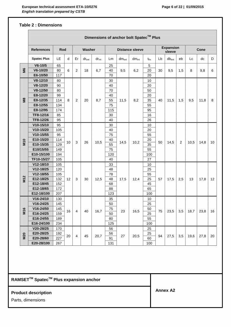
Specifications of intended use
Anchorages subject to:
Static and quasi-static loads (sizes M6 to M20),
Seismic loads (performance categories C1 and C2 for sizes M10 to M16),
Fire (sizes M6 to M20).
Base materials:
Cracked concrete and non-cracked concrete
Reinforced or unreinforced normal weight concrete of strength classes C20/25 at least to C50/60 at most according to EN 206: 2000-12.
Use conditions (Environmental conditions):
Structures subject to dry internal conditions. Design:
The anchorages are designed in accordance with the ETAG001 Annex C “Design Method for Anchorages” or CEN/TS 1992-4-4 " Design of fastenings for use in concrete” under the responsibility of an engineer experienced in anchorages and concrete work.
For seismic application the anchorages are designed in accordance with TR045 “Design of Metal Anchors For Use In Concrete Under Seismic Actions”.
For application with resistance under fire exposure the anchorages are designed in accordance with method given in TR020 “Evaluation of Anchorage in Concrete concerning Resistance to Fire”.
Verifiable calculation notes and drawings are prepared taking account of the loads to be anchored. The position of the anchor is indicated on the design drawings.
Installation:
Anchor installation carried out by appropriately qualified personnel and under the supervision of the person responsible for technical matters of the site.
Use of the anchor only as supplied by the manufacturer without exchanging the components of an anchor.
Anchor installation in accordance with the manufacturer’s specifications and drawings and using the appropriate tools.
Effective anchorage depth, edge distances and spacing not less than the specified values without minus tolerances.
Hole drilling by hammer drill.
Cleaning of the hole of drilling dust.
Application of specified torque moment using a calibrated torque wrench.
In case of aborted hole, drilling of new hole at a minimum distance of twice the depth of the aborted hole, or smaller distance provided the aborted drill hole is filled with high strength mortar and no shear or oblique tension loads in the direction of aborted hole.

European technical assessment ETA-10/0276
English translation prepared by CSTB
Page 8 of 22 | 01/09/2015
RAMSETTM SpatecTM Plus expansion anchor
Intended Use
Installation parameters
Annex B2
Table 3: Installation parameters
Embedment depth
hef
Drill hole diameter
Depth of drill hole
h1
Thickness of fixture
tfix
Setting torque
Tinst
Thickness of concrete
member
Diameter of clearance hole
df
[mm] [mm] [mm] [mm] [mm] [mm] [mm]
M6 V6-10/5
50 10 70
5
15 100 12 V6-10/20 20
E6-10/50 50
M8
V8-12/10
60 12 80
1
25 120 14
V8-12/20 10 V8-12/50 50 E8-12/20 20 E8-12/35 35 E8-12/55 55 E8-12/95 95
TF8-12/16 16
TF8-12/26 26
M1
0
V10-15/10
70 15 90
10
50 140 17
V10-15/20 20 V10-15/55 55 E10-15/20 20 E10-15/35 35 E10/15/55 55
E10-15/100 100 TF10-15/27 27
M1
2
V12-18/10
80 18 105
10
80 160 20
V12-18/25 25 V12-18/55 55 E12-18/25 25 E12-18/45 45 E12-18/65 65
E12-18/100 100
M1
6
V16-24/10
100 24 131
10
120 200 26
V16-24/25 25 V16-24/50 50 E16-24/25 25 E16-24/55 55
E16-24/100 100
M2
0
V20-28/25
125 28 157
25
200 250 31 E20-28/25 25 E20-28/60 60
E20-28/100 100

European technical assessment ETA-10/0276
English translation prepared by CSTB
Page 9 of 22 | 01/09/2015
RAMSETTM SpatecTM Plus expansion anchor
Intended Use
Installation parameters
Annex B2
Installed anchor
Table 4: Minimum spacing and edge distance, minimum thickness member
M6 M8 M10 M12 M16 M20
Min. member thickness hmin (mm) 100 120 140 160 200 250
Minimum spacing Smin (mm) 50 60 70 80 100 125
For Cmin = (mm) 80 100 100 160 180 300
Minimum edge distance Cmin (mm) 50 60 70 80 100 150
For Smin = (mm) 100 100 160 200 220 300
marking

European technical assessment ETA-10/0276
English translation prepared by CSTB
Page 10 of 22 | 01/09/2015
RAMSETTM SpatecTM Plus expansion anchor
Design according to ETAG001, Annex C
Characteristic resistance under tension loads
Annex C1
Table 5: Characteristic values for tension loads in case of static and quasi static loading
for design method A acc. ETAG 001, Annex C
M6 M8 M10 M12 M16 M20
Steel failure
Characteristic resistance NRk,s [kN] 16 29 46 67 126 196
Partial safety factor Ms [-] 1,50
Pull-through failure (cracked and non-cracked concrete) NRk,p = c x N0Rk,p
Characteristic resistance in concrete C20/25
non-cracked
N0Rk,p [kN]
-* 20 -* -* -* -*
cracked 5 12 16 -* -* -*
Partial safety factor Mp1) [-] 1,50 2)
Increasing factor for NRk
C30/37
c [-]
1,22
C40/50 1,41
C50/60 1,55
Concrete cone failure and splitting (cracked and non-cracked concrete)
Effective embedment depth hef [mm] 50 60 70 80 100 125
Partial safety factor Mc
=Msp1)
[-] 1,50 2)
ucr,N [-] 1,4
Char. spacing concrete cone failure scr,N [mm] 150 180 210 240 300 375
splitting failure scr,sp [mm] 300 300 300 300 380 480
Char. edge distance concrete cone failure ccr,N [mm] 75 90 105 120 150 185
splitting failure ccr,sp [mm] 150 150 150 150 190 240
* not decisive failure mode
1) In absence of other national regulations
2) The value contains an installation safety factor 2 = 1.0
European technical assessment ETA-10/0276
English translation prepared by CSTB
Page 11 of 22 | 01/09/2015
RAMSETTM SpatecTM Plus expansion anchor
Design according to ETAG001, Annex C
Characteristic resistance under shear loads
Annex C2
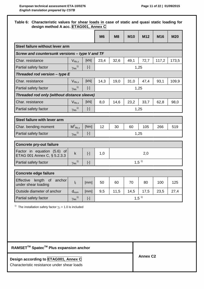
Table 6: Characteristic values for shear loads in case of static and quasi static loading for
design method A acc. ETAG001, Annex C
M6 M8 M10 M12 M16 M20
Steel failure without lever arm
Screw and countersunk versions – type V and TF
Char. resistance VRk,s [kN] 23,4 32,6 49,1 72,7 117,2 173,5
Partial safety factor Ms1) [-] 1,25
Threaded rod version – type E
Char. resistance VRk,s [kN] 14,3 19,0 31,0 47,4 93,1 109,9
Partial safety factor Ms1) [-] 1,25
Threaded rod only (without distance sleeve)
Char. resistance VRk,s [kN] 8,0 14,6 23,2 33,7 62,8 98,0
Partial safety factor Ms1) [-] 1,25
Steel failure with lever arm
Char. bending moment M0Rk,s [Nm] 12 30 60 105 266 519
Partial safety factor Ms1) [-] 1,25
Concrete pry-out failure
Factor in equation (5.6) of ETAG 001 Annex C, § 5.2.3.3
k [-] 1,0 2,0
Partial safety factor Mc1) [-] 1,5 1)
Concrete edge failure
Effective length of anchor under shear loading
lf [mm] 50 60 70 80 100 125
Outside diameter of anchor dnom [mm] 9,5 11,5 14,5 17,5 23,5 27,4
Partial safety factor Mc1) [-] 1,5 1)
1) The installation safety factor 2 = 1.0 is included

European technical assessment ETA-10/0276
English translation prepared by CSTB
Page 12 of 22 | 01/09/2015
RAMSETTM SpatecTM Plus expansion anchor
Design according to ETAG001, Annex C
Characteristic tension resistance under fire exposure
Annex C3
Table 7: Characteristic tension resistance under fire exposure
for design method A acc. ETAG001, Annex C
M6 M8 M10 M12 M16 M20
Steel failure
Characteristic resistance
R30 NRk,s,fi [kN] 0,9 2,8 4,5 17,6 32,8 51,1
R60 NRk,s,fi [kN] 0,6 2,1 3,3 11,4 21,3 33,2
R90 NRk,s,fi [kN] 0,4 1,3 2,1 5,3 9,8 15,3
R120 NRk,s,fi [kN] 0,3 0,9 1,5 2,2 4,1 6,4
Pullout failure
Characteristic resistance in concrete ≥ C20/25
R30 NRk,p,fi [kN] 1,2 3,0 4,0 - - -
R60 NRk,p,fi [kN] 1,2 3,0 4,0 - - -
R90 NRk,p,fi [kN] 1,2 3,0 4,0 - - -
R120 NRk,p,fi [kN] 1,0 2,4 3,2 - - -
Concrete cone and splitting failure 2)
Characteristic resistance in concrete ≥ C20/25
R30 N0Rk,c,fi [kN] 3,2 5,0 7,4 10,3 18,0 31,4
R60 N0Rk,c,fi [kN] 3,2 5,0 7,4 10,3 18,0 31,4
R90 N0Rk,c,fi [kN] 3,2 5,0 7,4 10,3 18,0 31,4
R120 N0Rk,c,fi [kN] 2,5 4,0 5,9 8,2 14,4 25,2
Characteristic spacing scr,N,fi [mm] 4 x hef
Characteristic edge distance ccr,N,fi [mm] 2 x hef
1) Design under fire exposure is performed according to the design method given in TR 020. Under fire exposure usually
cracked concrete is assumed. The design equations are given in TR 020, Section 2.2.1. 2)
As a rule, splitting failure can be neglected when cracked concrete and reinforcement is assumed.
In absence of other national regulation the partial safety factor for resistance under fire exposure M,fi = 1,0 is
recommended.
TR 020 covers design for fire exposure from one side. For fire attack from more than one side the edge distance must be increased to cmin≥ 300 mm and ≥ 2 ∙ hef.

European technical assessment ETA-10/0276
English translation prepared by CSTB
Page 13 of 22 | 01/09/2015
RAMSETTM SpatecTM Plus expansion anchor
Design according to ETAG001, Annex C
Characteristic shear resistance under fire exposure
Annex C4
Table 8: Characteristic shear resistance under fire exposure
for design method A acc. ETAG001, Annex C
M6 M8 M10 M12 M16 M20
Steel failure without lever arm
Characteristic resistance
R30 VRk,s,fi [kN] 0,9 2,8 4,5 17,6 32,8 51,1
R60 VRk,s,fi [kN] 0,6 2,1 3,3 11,4 21,3 33,2
R90 VRk,s,fi [kN] 0,4 1,3 2,1 5,3 9,8 15,3
R120 VRk,s,fi [kN] 0,3 0,9 1,5 2,2 4,1 6,4
Steel failure with lever arm
Characteristic resistance in concrete ≥ C20/25
R30 M0Rk,s,fi [kN] 0,9 2,9 5,8 27,3 69,5 135,5
R60 M0Rk,s,fi [kN] 0,6 2,1 4,2 17,8 45,2 88,1
R90 M0Rk,s,fi [kN] 0,4 1,3 2,7 8,2 20,9 40,7
R120 M0Rk,s,fi [kN] 0,3 0,9 1,9 3,4 8,7 17,0
Concrete pry-out failure
Factor in equation (5.6) of ETAG 01 Annex C, § 5.2.3.3
k [-] 1,0 2,0 2,0 2,0 2,0 2,0
Characteristic resistance
R30 VRk,cp,fi [kN] 3,2 5,0 7,4 10,3 18,0 31,4
R60 VRk, cp,fi [kN] 3,2 5,0 7,4 10,3 18,0 31,4
R90 VRk, cp,fi [kN] 3,2 5,0 7,4 10,3 18,0 31,4
R120 VRk, cp,fi [kN] 2,5 4,0 5,9 8,2 14,4 25,2
Concrete edge failure
Eff. length of anchor under shear loading
lf [mm] 50 60 70 80 100 125
Outside diameter of anchor dnom [mm] 6 8 10 12 16 20
1) Design under fire exposure is performed according to the design method given in TR 020. Under fire exposure
usually cracked concrete is assumed. The design equations are given in TR 020, Section 2.2.2.
In absence of other national regulation the partial safety factor for resistance under fire exposure M,fi = 1,0 is
recommended.
TR 020 covers design for fire exposure from one side. For fire attack from more than one side the edge distance must be increased to cmin ≥ 300 mm and ≥ 2 ∙ hef.

European technical assessment ETA-10/0276
English translation prepared by CSTB
Page 14 of 22 | 01/09/2015
RAMSETTM SpatecTM Plus expansion anchor
Design according to CEN/TS 1992-4
Characteristic resistance under tension loads
Annex C5
Table 9: Characteristic values for tension loads in case of static and quasi static loading
for design method A acc. CEN/TS 1992-4
M6 M8 M10 M12 M16 M20
Steel failure
Characteristic resistance NRk,s [kN] 16 29 46 67 126 196
Partial safety factor Ms [-] 1,50 1,50 1,50 1,50 1,50 1,50
Pull-through failure in cracked and non-cracked concrete NRk,p = c x N0Rk,p
Characteristic resistance in concrete C20/25
non-cracked
N0Rk,p [kN]
-* 20 -* -* -* -*
cracked 5 12 16 -* -* -*
Partial safety factor Mp1) [-] 1,50 2)
Increasing factor for NRk
C30/37
c [-]
1,22
C40/50 1,41
C50/60 1,55
Concrete cone failure in cracked and non-cracked concrete
Effective embedment depth hef [mm] 50 60 70 80 100 125
Factor for cracked concrete kcr [-] 7,2
Factor for non-cracked concrete kucr [-] 10,1
Partial safety factor Mc
=Msp1)
[-] 1,50 2)
Char. spacing concrete cone failure scr,N [mm] 150 180 210 240 300 375
splitting failure scr,sp [mm] 300 300 300 300 380 480
Char. edge distance concrete cone failure ccr,N [mm] 75 90 105 120 150 185
splitting failure ccr,sp [mm] 150 150 150 150 190 240
* not decisive failure mode
1) In absence of other national regulations
2) The value contains an installation safety factor 2 = 1.0

European technical assessment ETA-10/0276
English translation prepared by CSTB
Page 15 of 22 | 01/09/2015
RAMSETTM SpatecTM Plus expansion anchor
Design according to CEN/TS 1992-4
Characteristic resistance under shear loads
Annex C6
Table 10: Characteristic values for shear loads in case of static and quasi static loading for
design method A acc. CEN/TS 1992-4
M6 M8 M10 M12 M16 M20
Steel failure without lever arm
Screw and countersunk versions – type V and TF
Char. resistance VRk,s [kN] 23,4 32,6 49,1 72,7 117,2 173,5
Factor considering ductility k2 [-] 0,8
Partial safety factor Ms1) [-] 1,25
Threaded rod version – type E
Char. resistance VRk,s [kN] 14,3 19,0 31,0 47,4 93,1 109,9
Factor considering ductility k2 [-] 0,8
Partial safety factor Ms1) [-] 1,25
Threaded rod only (without distance sleeve)
Char. resistance VRk,s [kN] 8,0 14,6 23,2 33,7 62,8 98,0
Factor considering ductility k2 [-] 0,8
Partial safety factor Ms1) [-] 1,25
Steel failure with lever arm
Char. bending moment M0Rk,s [Nm] 12 30 60 105 266 519
Partial safety factor Ms1) [-] 1,25
Concrete pry-out failure
Factor in equation (16) of CEN/TS 1992-4-4, § 6.2.2.3
k3 [-] 1,0 2,0
Partial safety factor Mc1) [-] 1,5 1)
Concrete edge failure
Effective length of anchor under shear loading
lf [mm] 50 60 70 80 100 125
Outside diameter of anchor dnom [mm] 9,5 11,5 14,5 17,5 23,5 27,4
Partial safety factor Mc1) [-] 1,5 1)
1) The installation safety factor 2 = 1.0 is included
European technical assessment ETA-10/0276
English translation prepared by CSTB
Page 16 of 22 | 01/09/2015
RAMSETTM SpatecTM Plus expansion anchor
Design according to CEN/TS 1992-4
Characteristic tension resistance under fire exposure
Annex C7
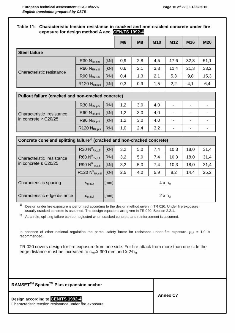
Table 11: Characteristic tension resistance in cracked and non-cracked concrete under fire
exposure for design method A acc. CEN/TS 1992-4
M6 M8 M10 M12 M16 M20
Steel failure
Characteristic resistance
R30 NRk,s,fi [kN] 0,9 2,8 4,5 17,6 32,8 51,1
R60 NRk,s,fi [kN] 0,6 2,1 3,3 11,4 21,3 33,2
R90 NRk,s,fi [kN] 0,4 1,3 2,1 5,3 9,8 15,3
R120 NRk,s,fi [kN] 0,3 0,9 1,5 2,2 4,1 6,4
Pullout failure (cracked and non-cracked concrete)
Characteristic resistance in concrete ≥ C20/25
R30 NRk,p,fi [kN] 1,2 3,0 4,0 - - -
R60 NRk,p,fi [kN] 1,2 3,0 4,0 - - -
R90 NRk,p,fi [kN] 1,2 3,0 4,0 - - -
R120 NRk,p,fi [kN] 1,0 2,4 3,2 - - -
Concrete cone and splitting failure2) (cracked and non-cracked concrete)
Characteristic resistance in concrete ≥ C20/25
R30 N0Rk,c,fi [kN] 3,2 5,0 7,4 10,3 18,0 31,4
R60 N0Rk,c,fi [kN] 3,2 5,0 7,4 10,3 18,0 31,4
R90 N0Rk,c,fi [kN] 3,2 5,0 7,4 10,3 18,0 31,4
R120 N0Rk,c,fi [kN] 2,5 4,0 5,9 8,2 14,4 25,2
Characteristic spacing scr,N,fi [mm] 4 x hef
Characteristic edge distance ccr,N,fi [mm] 2 x hef
1) Design under fire exposure is performed according to the design method given in TR 020. Under fire exposure
usually cracked concrete is assumed. The design equations are given in TR 020, Section 2.2.1. 2)
As a rule, splitting failure can be neglected when cracked concrete and reinforcement is assumed.
In absence of other national regulation the partial safety factor for resistance under fire exposure M,fi = 1,0 is
recommended.
TR 020 covers design for fire exposure from one side. For fire attack from more than one side the edge distance must be increased to cmin≥ 300 mm and ≥ 2∙hef.

European technical assessment ETA-10/0276
English translation prepared by CSTB
Page 17 of 22 | 01/09/2015
RAMSETTM SpatecTM Plus expansion anchor
Design according to CEN/TS 1992-4
Characteristic shear resistance under fire exposure
Annex C8
Table 12: Characteristic shear resistance in cracked and non-cracked concrete under fire
exposure for design method A acc. CEN/TS 1992-4
M6 M8 M10 M12 M16 M20
Steel failure without lever arm
Characteristic resistance
R30 VRk,s,fi [kN] 0,9 2,8 4,5 17,6 32,8 51,1
R60 VRk,s,fi [kN] 0,6 2,1 3,3 11,4 21,3 33,2
R90 VRk,s,fi [kN] 0,4 1,3 2,1 5,3 9,8 15,3
R120 VRk,s,fi [kN] 0,3 0,9 1,5 2,2 4,1 6,4
Steel failure with lever arm
Characteristic resistance in concrete ≥ C20/25
R30 M0Rk,s,fi [kN] 0,9 2,9 5,8 27,3 69,5 135,5
R60 M0Rk,s,fi [kN] 0,6 2,1 4,2 17,8 45,2 88,1
R90 M0Rk,s,fi [kN] 0,4 1,3 2,7 8,2 20,9 40,7
R120 M0Rk,s,fi [kN] 0,3 0,9 1,9 3,4 8,7 17,0
Concrete pry-out failure
Factor in equation (16) of CEN/TS 1992-4-4, § 6.2.2.3
k3 1,0 2,0 2,0 2,0 2,0 2,0
Characteristic resistance
R30 VRk,cp,fi [kN] 3,2 5,0 7,4 10,3 18,0 31,4
R60 VRk, cp,fi [kN] 3,2 5,0 7,4 10,3 18,0 31,4
R90 VRk, cp,fi [kN] 3,2 5,0 7,4 10,3 18,0 31,4
R120 VRk, cp,fi [kN] 2,5 4,0 5,9 8,2 14,4 25,2
Concrete edge failure
Eff. length of anchor under shear loading
lf [mm] 50 60 70 80 100 125
Outside diameter of anchor dnom [mm] 6 8 10 12 16 20
1) Design under fire exposure is performed according to the design method given in TR 020. Under fire exposure usually
cracked concrete is assumed. The design equations are given in TR 020, Section 2.2.2.
TR 020 covers design for fire exposure from one side. For fire attack from more than one side the edge distance must be increased to cmin ≥ 300 mm and ≥ 2 ∙ hef.

European technical assessment ETA-10/0276
English translation prepared by CSTB
Page 18 of 22 | 01/09/2015
RAMSETTM SpatecTM Plus expansion anchor
Seismic performance categories
Annex C9
The seismic performance of anchors subjected to seismic loading is categorized by performance categories C1 and C2. Seismic performance category C1 provides anchor capacities only in terms of resistances at ultimate limit state, while seismic performance category C2 provides anchor capacities in terms of both resistances at ultimate limit state and displacements at damage limitation state and ultimate limit state. Table 13 relates the seismic performance categories C1 and C2 to the seismicity level and building importance class. The level of seismicity is defined as a function of the product ag·S, where ag is the design ground acceleration on Type A ground and S the soil factor both in accordance with EN 1998-1. The value of ag or that of the product ag·S used in a Member State to define thresholds for the seismicity classes may be found in its National Annex of EN 1998-1 and may be different to the values given in Table 13. Furthermore, the assignment of the seismic performance categories C1 and C2 to the seismicity level and building importance classes is in the responsibility of each individual Member State.
Table 13 : Recommended seismic performance categories for metal anchors
Seismicity levela Importance Class acc. to EN 1998-1:2004, 4.2.5
Class ag·S c
I II III IV
Very low b ag·S ≤ 0,05 g No additional requirement
Low b 0,05 g < ag·S ≤ 0,10 g C1 C1
d or C2
e C2
> low ag·S > 0,10 g C1 C2
a The values defining the seismicity levels are may be found in the National Annex of EN 1988-1.
b Definition according to EN 1998-1:2004, 3.2.1.
c ag = design ground acceleration on Type A ground (EN 1998-1:2004, 3.2.1),
S = soil factor (see e.g. EN 1998-1:2004, 3.2.2).
d C1 for Type 'B' connections (see TR045 §5.1) for fixings of non-structural elements to structures
e C2 for Type 'A' connections (see TR045 § 5.1) for fixings structural elements to structures
European technical assessment ETA-10/0276
English translation prepared by CSTB
Page 19 of 22 | 01/09/2015
RAMSETTM SpatecTM Plus expansion anchor
Reduction factors and characteristic seismic resistances
Annex C10
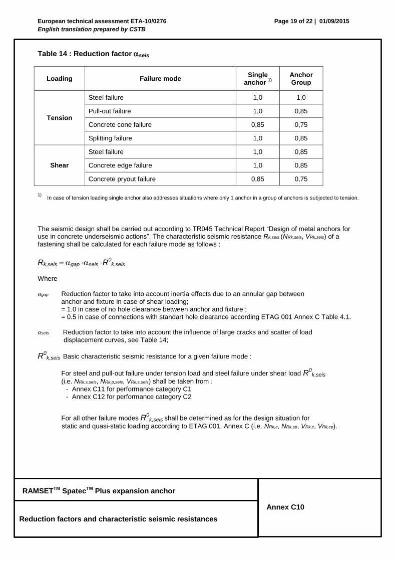
Table 14 : Reduction factor seis
Loading Failure mode Single
anchor 1)
Anchor Group
Tension
Steel failure 1,0 1,0
Pull-out failure 1,0 0,85
Concrete cone failure 0,85 0,75
Splitting failure 1,0 0,85
Shear
Steel failure 1,0 0,85
Concrete edge failure 1,0 0,85
Concrete pryout failure 0,85 0,75
1) In case of tension loading single anchor also addresses situations where only 1 anchor in a group of anchors is subjected to tension.
The seismic design shall be carried out according to TR045 Technical Report “Design of metal anchors for use in concrete underseismic actions”. The characteristic seismic resistance Rk,seis (NRk,seis, VRk,seis) of a fastening shall be calculated for each failure mode as follows :
Rk,seis gap seis R0
k,seis Where αgap Reduction factor to take into account inertia effects due to an annular gap between anchor and fixture in case of shear loading; = 1.0 in case of no hole clearance between anchor and fixture ; = 0.5 in case of connections with standart hole clearance according ETAG 001 Annex C Table 4.1.
αseis Reduction factor to take into account the influence of large cracks and scatter of load displacement curves, see Table 14;
R0k,seis Basic characteristic seismic resistance for a given failure mode :
For steel and pull-out failure under tension load and steel failure under shear load R0k,seis
(i.e. NRk,s,seis, NRk,p,seis, VRk,s,seis) shall be taken from : - Annex C11 for performance category C1 - Annex C12 for performance category C2
For all other failure modes R0k,seis shall be determined as for the design situation for
static and quasi-static loading according to ETAG 001, Annex C (i.e. NRk,c, NRk,sp, VRk,c, VRk,cp).
European technical assessment ETA-10/0276
English translation prepared by CSTB
Page 20 of 22 | 01/09/2015
RAMSETTM SpatecTM Plus expansion anchor
Design according to TR045
Characteristic resistance under seismic actions
Annex C11
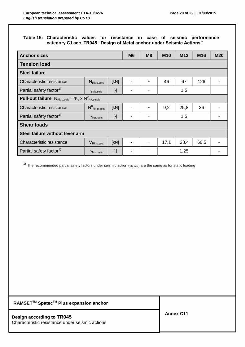
Table 15: Characteristic values for resistance in case of seismic performance
category C1 acc. TR045 “Design of Metal anchor under Seismic Actions”
Anchor sizes M6 M8 M10 M12 M16 M20
Tension load
Steel failure
Characteristic resistance NRk,s,seis [kN] - - 46 67 126 -
Partial safety factor1) Ms,seis [-] - - 1,5
Pull-out failure NRk,p,seis = c x N0Rk,p,seis
Characteristic resistance N0Rk,p,seis [kN] - - 9,2 25,8 36 -
Partial safety factor1) Mp, seis [-] - - 1,5 -
Shear loads
Steel failure without lever arm
Characteristic resistance VRk,s,seis [kN] - - 17,1 28,4 60,5 -
Partial safety factor1) Ms, seis [-] - - 1,25 -
1) The recommended partial safety factors under seismic action (M,seis) are the same as for static loading
European technical assessment ETA-10/0276
English translation prepared by CSTB
Page 21 of 22 | 01/09/2015
RAMSETTM SpatecTM Plus expansion anchor
Design according to TR045
Characteristic resistance under seismic actions
Annex C12
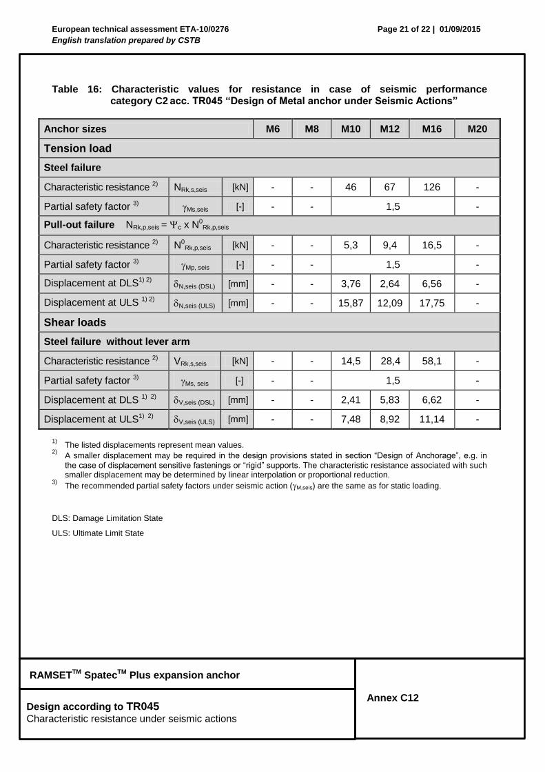
Table 16: Characteristic values for resistance in case of seismic performance category C2 acc. TR045 “Design of Metal anchor under Seismic Actions”
Anchor sizes M6 M8 M10 M12 M16 M20
Tension load
Steel failure
Characteristic resistance 2) NRk,s,seis [kN] - - 46 67 126 -
Partial safety factor 3) Ms,seis [-] - - 1,5 -
Pull-out failure NRk,p,seis = c x N0Rk,p,seis
Characteristic resistance 2) N0Rk,p,seis [kN] - - 5,3 9,4 16,5 -
Partial safety factor 3) Mp, seis [-] - - 1,5 -
Displacement at DLS1) 2) N,seis (DSL) [mm] - - 3,76 2,64 6,56 -
Displacement at ULS 1) 2) N,seis (ULS) [mm] - - 15,87 12,09 17,75 -
Shear loads
Steel failure without lever arm
Characteristic resistance 2) VRk,s,seis [kN] - - 14,5 28,4 58,1 -
Partial safety factor 3) Ms, seis [-] - - 1,5 -
Displacement at DLS 1) 2) V,seis (DSL) [mm] - - 2,41 5,83 6,62 -
Displacement at ULS1) 2) V,seis (ULS) [mm] - - 7,48 8,92 11,14 -
1)
The listed displacements represent mean values. 2)
A smaller displacement may be required in the design provisions stated in section “Design of Anchorage”, e.g. in
the case of displacement sensitive fastenings or “rigid” supports. The characteristic resistance associated with such smaller displacement may be determined by linear interpolation or proportional reduction.
3) The recommended partial safety factors under seismic action (M,seis) are the same as for static loading.
DLS: Damage Limitation State
ULS: Ultimate Limit State
European technical assessment ETA-10/0276
English translation prepared by CSTB
Page 22 of 22 | 01/09/2015
RAMSETTM SpatecTM Plus expansion anchor
Design
Displacements
Annex C13
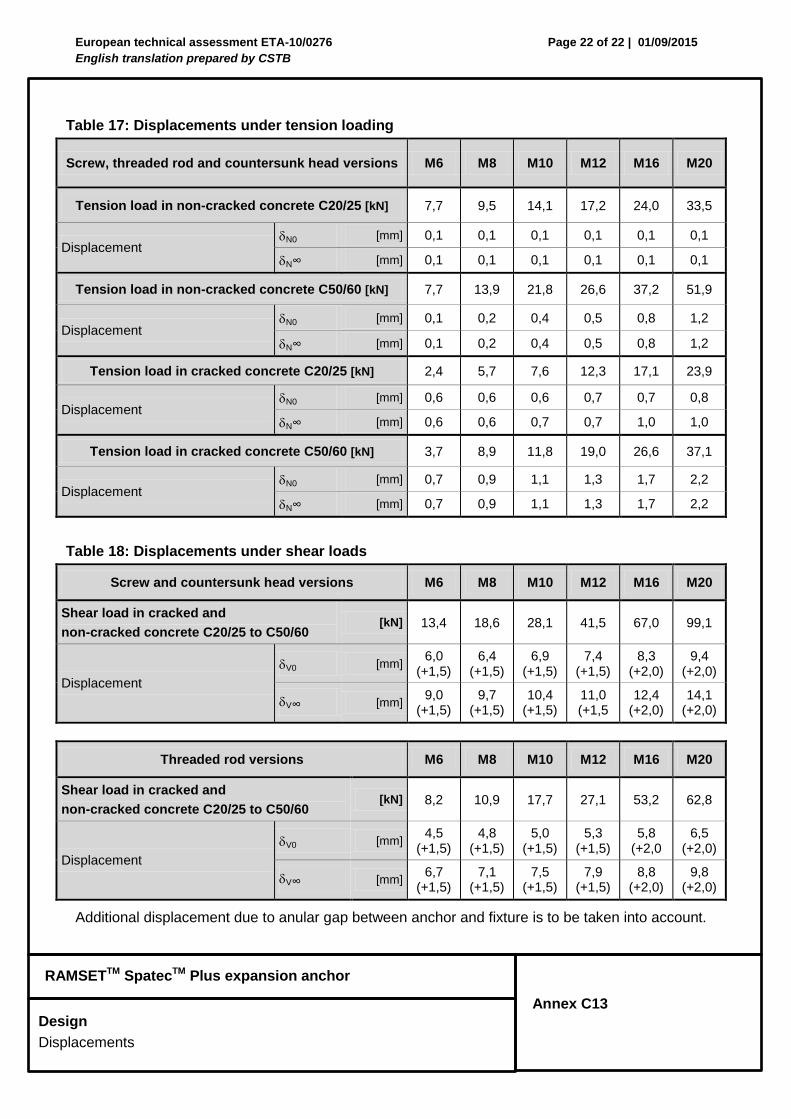
Table 17: Displacements under tension loading
Screw, threaded rod and countersunk head versions M6 M8 M10 M12 M16 M20
Tension load in non-cracked concrete C20/25 [kN] 7,7 9,5 14,1 17,2 24,0 33,5
Displacement N0 [mm] 0,1 0,1 0,1 0,1 0,1 0,1
N∞ [mm] 0,1 0,1 0,1 0,1 0,1 0,1
Tension load in non-cracked concrete C50/60 [kN] 7,7 13,9 21,8 26,6 37,2 51,9
Displacement N0 [mm] 0,1 0,2 0,4 0,5 0,8 1,2
N∞ [mm] 0,1 0,2 0,4 0,5 0,8 1,2
Tension load in cracked concrete C20/25 [kN] 2,4 5,7 7,6 12,3 17,1 23,9
Displacement N0 [mm] 0,6 0,6 0,6 0,7 0,7 0,8
N∞ [mm] 0,6 0,6 0,7 0,7 1,0 1,0
Tension load in cracked concrete C50/60 [kN] 3,7 8,9 11,8 19,0 26,6 37,1
Displacement N0 [mm] 0,7 0,9 1,1 1,3 1,7 2,2
N∞ [mm] 0,7 0,9 1,1 1,3 1,7 2,2
Table 18: Displacements under shear loads
Screw and countersunk head versions M6 M8 M10 M12 M16 M20
Shear load in cracked and
non-cracked concrete C20/25 to C50/60 [kN] 13,4 18,6 28,1 41,5 67,0 99,1
Displacement
V0 [mm] 6,0
(+1,5) 6,4
(+1,5) 6,9
(+1,5) 7,4
(+1,5) 8,3
(+2,0) 9,4
(+2,0)
V∞ [mm] 9,0
(+1,5) 9,7
(+1,5) 10,4
(+1,5) 11,0 (+1,5
12,4 (+2,0)
14,1 (+2,0)
Threaded rod versions M6 M8 M10 M12 M16 M20
Shear load in cracked and
non-cracked concrete C20/25 to C50/60 [kN] 8,2 10,9 17,7 27,1 53,2 62,8
Displacement
V0 [mm] 4,5
(+1,5) 4,8
(+1,5) 5,0
(+1,5) 5,3
(+1,5) 5,8
(+2,0 6,5
(+2,0)
V∞ [mm] 6,7
(+1,5) 7,1
(+1,5) 7,5
(+1,5) 7,9
(+1,5) 8,8
(+2,0) 9,8
(+2,0)
Additional displacement due to anular gap between anchor and fixture is to be taken into account.