84 avenue Jean Jaurès CHAMPS-SUR-MARNE Fax : … · Cheville métallique en acier galvanisé, à...
22
Centre Scientifique et Technique du Bâtiment 84 avenue Jean Jaurès CHAMPS-SUR-MARNE F-77447 Marne-la-Vallée Cedex 2 Tél. : (33) 01 64 68 82 82 Fax : (33) 01 60 05 70 37 Member of www.eota.eu European Technical Assessment ETA-02/0042 of 07/09/2015 English translation prepared by CSTB - Original version in French language General Part Nom commercial Trade name Hilti HSL3 Famille de produit Product family Cheville métallique en acier galvanisé, à expansion par vissage à couple contrôlé, de fixation dans le béton : diamètres M8, M10, M12, M16, M20 et M24. Torque-controlled expansion anchor, made of galvanised steel, for use in concrete: sizes M8, M10, M12, M16, M20 and M24. Titulaire Manufacturer Hilti Corporation Feldkircherstrasse 100 FL-9494 Schaan Principality of Liechtenstein Usine de fabrication e Manufacturing plants Hilti plants Cette evaluation contient: This Assessment contains 22 pages incluant 19 pages d’annexes qui font partie intégrante de cette évaluation 22 pages including 19 annex pages which form an integral part of this assessment Base de l‘ETE Basis of ETA ETAG 001, Version April 2013, utilisée en tant que EAD ETAG 001, Edition April 2013 used as EAD Cette evaluation remplace: This Assessment replaces ATE-02/0042 délivré le10/01/2013 ETA-02/0042 issued at 10/01/2013 Translations of this European Technical Assessment in other languages shall fully correspond to the original issued document and should be identified as such. Communication of this European Technical Assessment, including transmission by electronic means, shall be in full. However, partial reproduction may be made, with the written consent of the issuing Technical Assessment Body. Any partial reproduction has to be identified as such.
Transcript of 84 avenue Jean Jaurès CHAMPS-SUR-MARNE Fax : … · Cheville métallique en acier galvanisé, à...

Centre Scientifique et
Technique du Bâtiment 84 avenue Jean Jaurès CHAMPS-SUR-MARNE F-77447 Marne-la-Vallée Cedex 2 Tél. : (33) 01 64 68 82 82 Fax : (33) 01 60 05 70 37
Member of
www.eota.eu
European Technical Assessment
ETA-02/0042 of 07/09/2015
English translation prepared by CSTB - Original version in French language
General Part
Nom commercial Trade name
Hilti HSL3
Famille de produit Product family
Cheville métallique en acier galvanisé, à expansion par vissage à couple contrôlé, de fixation dans le béton : diamètres M8, M10, M12, M16, M20 et M24.
Torque-controlled expansion anchor, made of galvanised steel, for use in concrete: sizes M8, M10, M12, M16, M20 and M24.
Titulaire Manufacturer
Hilti Corporation Feldkircherstrasse 100 FL-9494 Schaan Principality of Liechtenstein
Usine de fabrication e Manufacturing plants
Hilti plants
Cette evaluation contient: This Assessment contains
22 pages incluant 19 pages d’annexes qui font partie intégrante de cette évaluation 22 pages including 19 annex pages which form an integral part of this assessment
Base de l‘ETE Basis of ETA
ETAG 001, Version April 2013, utilisée en tant que EAD
ETAG 001, Edition April 2013 used as EAD
Cette evaluation remplace: This Assessment replaces
ATE-02/0042 délivré le10/01/2013 ETA-02/0042 issued at 10/01/2013
Translations of this European Technical Assessment in other languages shall fully correspond to the original issued document and should be identified as such. Communication of this European Technical Assessment, including transmission by electronic means, shall be in full. However, partial reproduction may be made, with the written consent of the issuing Technical Assessment Body. Any partial reproduction has to be identified as such.

European technical assessment ETA-02/0042
English translation prepared by CSTB
Page 2 of 22 | 07 / 09 / 2015
Specific Part
1 Technical description of the product
The Hilti heavy duty HSL-3 anchor in the range of M8 to M24 is a torque-controlled expansion anchor made of galvanised steel. The Hilti heavy duty HSL-3 anchor is available in five versions: an hexagonal bolt version (HSL-3) in the range of M8 to M24; a threaded rod version (HSL-3-G) in the range of M8 to M24; a safety cap version (HSL-3-B) in the range of M12 to M24; a socket hexagonal head version (HSL-3-SH) in the range M8 to M12; a countersunk version (HSL-3-SK) in the range of M8 to M12. It is placed into a drilled hole and anchored by torque-controlled expansion.
The illustration and the description of the product are given in Annexes A.
2 Specification of the intended use
The performances given in Section 3 are only valid if the anchor is used in compliance with the specifications and conditions given in Annexes B.
The provisions made in this European technical assessment are based on an assumed working life of the anchor of 50 years. The indications given on the working life cannot be interpreted as a guarantee given by the producer, but are to be regarded only as a means for choosing the right products in relation to the expected economically reasonable working life of the works.
3 Performance of the product
3.1 Mechanical resistance and stability (BWR 1)
Essential characteristic Performance
Characteristic tension resistance in case of static and quasi-static loading according ETAG001, Annex C and CEN/TS 1992-4
See Annex C1
Characteristic shear resistance in case of static and quasi-static loading according ETAG001, Annex C and CEN/TS 1992-4
See Annex C2
Characteristic shear resistance in case of seismic performance category C1 according EOTA TR045
See Annex C3
Characteristic shear resistance in case of seismic performance category C2 according EOTA TR045
See Annex C4
Displacements under tension and shear loads in case of static and quasi-static loading
See Annex C5
Displacements under tension and shear loads in case of seismic performance category C1
See Annex C6
Displacements under tension and shear loads in case of seismic performance category C1
See Annex C7
3.2 Safety in case of fire (BWR 2)
Essential characteristic Performance
Reaction to fire Anchorages satisfy requirements for Class A1
3.3 Hygiene, health and the environment (BWR 3)
Regarding dangerous substances contained in this European technical approval, there may be requirements applicable to the products falling within its scope (e.g. transposed European legislation and national laws, regulations and administrative provisions). In order to meet the provisions of the Construction Products Directive, these requirements need also to be complied with, when and where they apply.

European technical assessment ETA-02/0042
English translation prepared by CSTB
Page 3 of 22 | 07 / 09 / 2015
3.4 Safety in use (BWR 4)
For Basic requirement Safety in use the same criteria are valid as for Basic Requirement Mechanical resistance and stability.
3.5 Protection against noise (BWR 5)
Not relevant.
3.6 Energy economy and heat retention (BWR 6)
Not relevant.
3.7 Sustainable use of natural resources ( (BWR 7)
For the sustainable use of natural resources no performance was determined for this product.
3.8 General aspects relating to fitness for use
Durability and Serviceability are only ensured if the specifications of intended use according to Annex B 1 are kept.
4 Assessment and verification of constancy of performance (AVCP)
According to the Decision 96/582/EC of the European Commission1, as amended, the system of
assessment and verification of constancy of performance (see Annex V to Regulation (EU) No 305/2011) given in the following table apply.
Product Intended use Level
or Class System
Metal anchors for use in concrete
For fixing and/or supporting to concrete, structural elements (which contributes to the stability of the works) or heavy units
― 1
5 Technical details necessary for the implementation of the AVCP system
Technical details necessary for the implementation of the Assessment and verification of constancy of performance (AVCP) system are laid down in the control plan deposited at Centre Scientifique et Technique du Bâtiment.
The manufacturer shall, on the basis of a contract, involve a notified body approved in the field of anchors for issuing the certificate of conformity CE based on the control plan.
Issued in Marne La Vallée on 07-09-2015 by
Charles Baloche The original French version is signed
Directeur technique
1 Official Journal of the European Communities L 254 of 08.10.1996

European technical assessment ETA-02/0042
English translation prepared by CSTB
Page 4 of 22 | 07 / 09 / 2015
Cone
Expansion sleeve Collapsible element
Distance
sleeve
Washer
Hexagon
Bolt
Effective anchorage depth
Borehole depth
Thickness of concrete member
Fixture
thickness
Tinst
Marking
Product description – Installation condition
Intended use:
HSL-3, HSL-3-G, HSL-3-B, HSL-3-SK, HSL-3-SH for use in cracked or non-cracked concrete in dry internal conditions only
Annex A1
Hilti heavy duty anchor HSL-3
Product description – Installation condition
HSL-3

European technical assessment ETA-02/0042
English translation prepared by CSTB
Page 5 of 22 | 07 / 09 / 2015
M8, M10, M12
M16
M20, M24
Annex A2
Hilti heavy duty anchor HSL-3
Product description – Different version of HSL3
HSL-3, HSL3-G, HSL-3-B, HSL3-SH and HSL-3-SK

European technical assessment ETA-02/0042
English translation prepared by CSTB
Page 6 of 22 | 07 / 09 / 2015
Table 1: Material specification of HSL-3, HSL3-G, HSL-3-B, HSL3-SH and HSL-3-SK
Part Designation HSL-3 (galvanized 5µm)
1 Cone Steel, DIN 1654-4
2 Expansion sleeve Steel, DIN 1654-4
3 Collapsible element POM plastic element
4 Distance sleeve Carbon steel DIN 2393 T1
5 Washer St 37 DIN 1544
6 Hexagonal bolt Steel 8.8 acc. DIN EN ISO 898-1
7 Hexagon nut Grade 8 (DIN 934, in future EN 24032)
8 Threaded rod Steel 8.8 acc. DIN EN ISO 898-1
9 Safety cap version Steel 8.8 acc. DIN EN ISO 898-1
10 Hexagonal socket head Steel 8.8 acc. DIN EN ISO 898-1
11 Countersunk bolt Steel 8.8 acc. DIN ISO 4759-1 and DIN EN ISO 898-1 12 Cup washer 11SMnPb37 + C MOD HN389
Annex A3
Hilti heavy duty anchor HSL-3
Product description - Material of anchor
HSL-3, HSL3-G, HSL-3-B, HSL3-SH and HSL-3-SK
European technical assessment ETA-02/0042
English translation prepared by CSTB
Page 7 of 22 | 07 / 09 / 2015
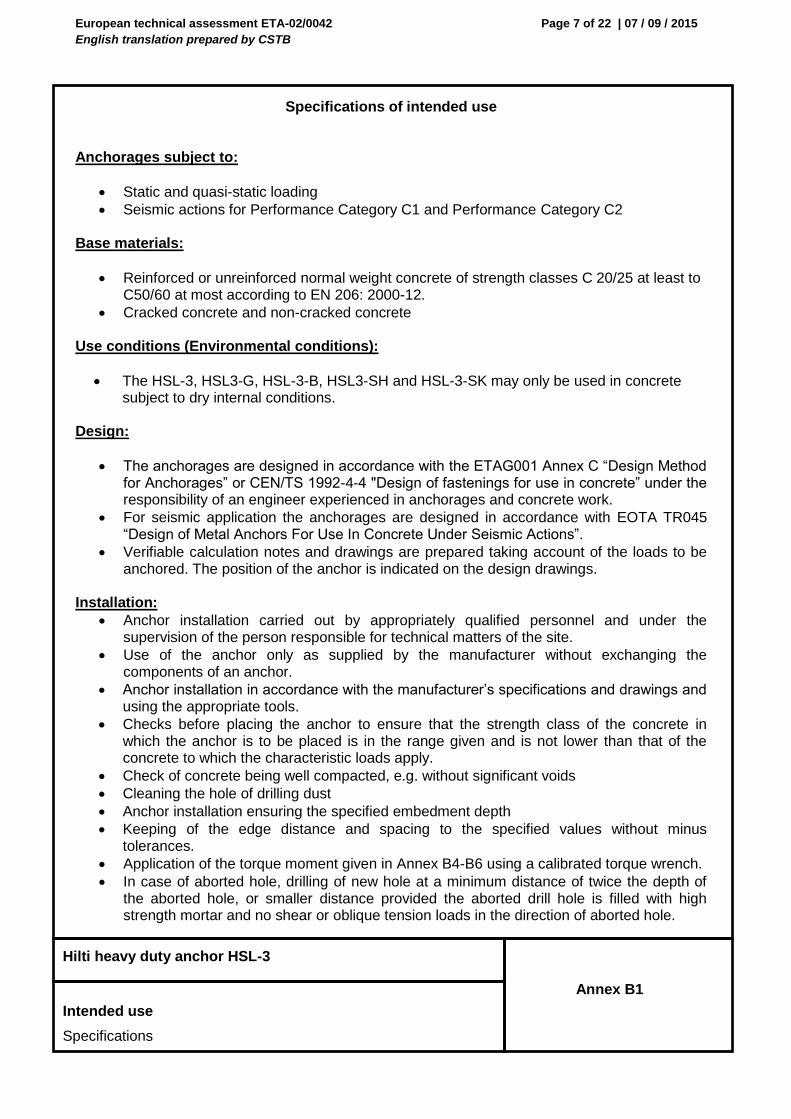
Specifications of intended use
Anchorages subject to:
Static and quasi-static loading
Seismic actions for Performance Category C1 and Performance Category C2 Base materials:
Reinforced or unreinforced normal weight concrete of strength classes C 20/25 at least to C50/60 at most according to EN 206: 2000-12.
Cracked concrete and non-cracked concrete Use conditions (Environmental conditions):
The HSL-3, HSL3-G, HSL-3-B, HSL3-SH and HSL-3-SK may only be used in concrete subject to dry internal conditions.
Design:
The anchorages are designed in accordance with the ETAG001 Annex C “Design Method for Anchorages” or CEN/TS 1992-4-4 "Design of fastenings for use in concrete” under the responsibility of an engineer experienced in anchorages and concrete work.
For seismic application the anchorages are designed in accordance with EOTA TR045 “Design of Metal Anchors For Use In Concrete Under Seismic Actions”.
Verifiable calculation notes and drawings are prepared taking account of the loads to be anchored. The position of the anchor is indicated on the design drawings.
Installation:
Anchor installation carried out by appropriately qualified personnel and under the supervision of the person responsible for technical matters of the site.
Use of the anchor only as supplied by the manufacturer without exchanging the components of an anchor.
Anchor installation in accordance with the manufacturer’s specifications and drawings and using the appropriate tools.
Checks before placing the anchor to ensure that the strength class of the concrete in which the anchor is to be placed is in the range given and is not lower than that of the concrete to which the characteristic loads apply.
Check of concrete being well compacted, e.g. without significant voids
Cleaning the hole of drilling dust
Anchor installation ensuring the specified embedment depth
Keeping of the edge distance and spacing to the specified values without minus tolerances.
Application of the torque moment given in Annex B4-B6 using a calibrated torque wrench.
In case of aborted hole, drilling of new hole at a minimum distance of twice the depth of the aborted hole, or smaller distance provided the aborted drill hole is filled with high strength mortar and no shear or oblique tension loads in the direction of aborted hole.
Annex B1
Hilti heavy duty anchor HSL-3
Intended use
Specifications

European technical assessment ETA-02/0042
English translation prepared by CSTB
Page 8 of 22 | 07 / 09 / 2015
Table 2: Intended use of HSL-3, HSL3-G, HSL-3-B, HSL3-SH and HSL-3-SK
M8 M10 M12 M16 M20 M24
Static and quasi static
HSL-3, HSL3-G,
HSL3-SH,
HSL-3-SK
HSL-3, HSL3-G,
HSL3-SH,
HSL-3-SK
HSL-3, HSL3-G, HSL-3-B, HSL3-SH,
HSL-3-SK
HSL-3, HSL3-G, HSL-3-B,
HSL-3, HSL3-G, HSL-3-B,
HSL-3, HSL3-G, HSL-3-B,
Seismic Category C1
HSL-3, HSL3-G,
HSL3-SH,
HSL-3-SK
HSL-3, HSL3-G,
HSL3-SH,
HSL-3-SK
HSL-3, HSL3-G, HSL-3-B, HSL3-SH,
HSL-3-SK
HSL-3, HSL3-G, HSL-3-B,
HSL-3, HSL3-G, HSL-3-B,
HSL-3, HSL-3-B
Seismic Category C2
HSL-3, HSL3-G,
HSL3-SH,
HSL-3-SK
HSL-3, HSL3-G, HSL-3-B, HSL3-SH,
HSL-3-SK
HSL-3, HSL3-G, HSL-3-B,
HSL-3, HSL3-G, HSL-3-B,
Annex B2
Hilti heavy duty anchor HSL-3
Intended use
Specifications
European technical assessment ETA-02/0042
English translation prepared by CSTB
Page 9 of 22 | 07 / 09 / 2015
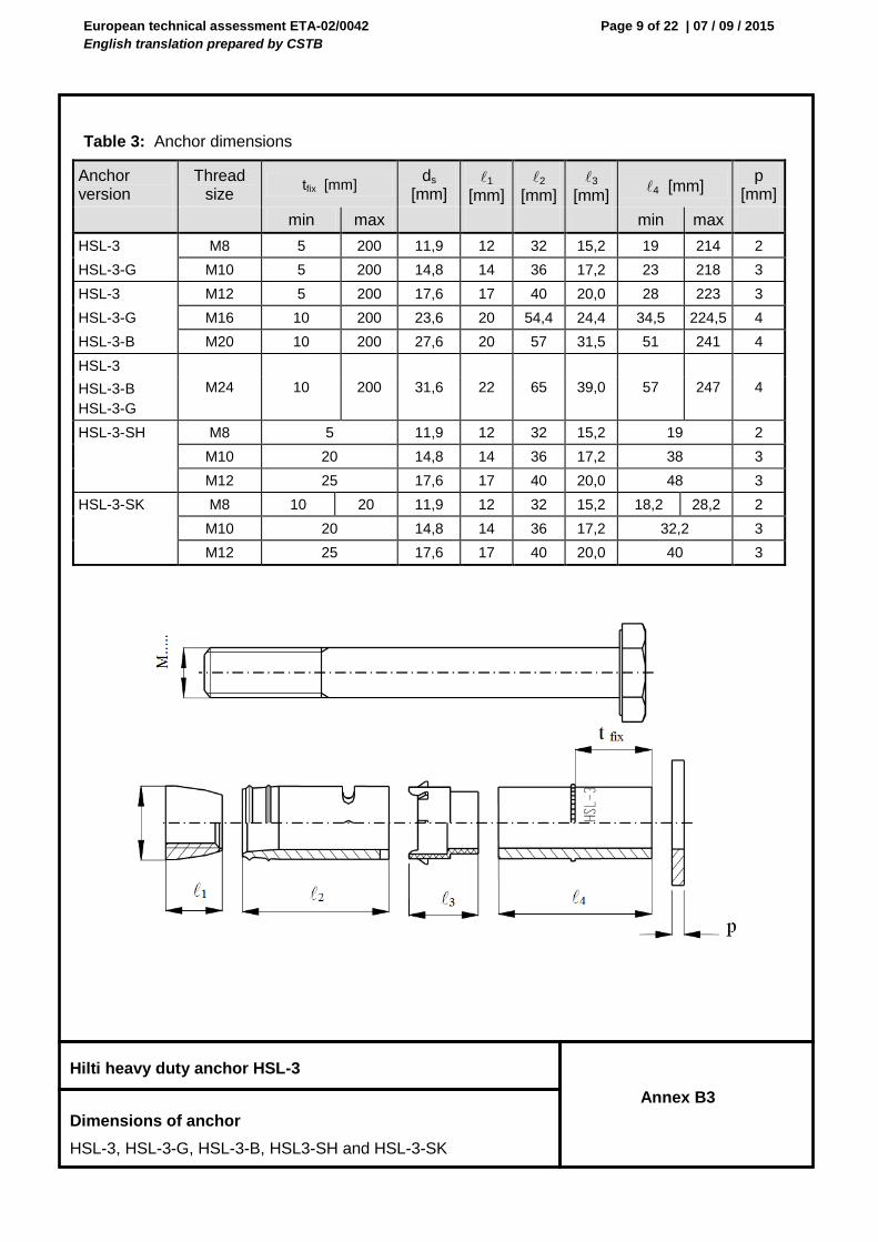
Table 3: Anchor dimensions
Anchor version
Thread size
tfix [mm] ds
[mm] 1
[mm] 2
[mm] 3
[mm] 4 [mm]
p [mm]
min max min max
HSL-3 M8 5 200 11,9 12 32 15,2 19 214 2
HSL-3-G M10 5 200 14,8 14 36 17,2 23 218 3
HSL-3 M12 5 200 17,6 17 40 20,0 28 223 3
HSL-3-G M16 10 200 23,6 20 54,4 24,4 34,5 224,5 4
HSL-3-B M20 10 200 27,6 20 57 31,5 51 241 4
HSL-3
M24 10 200 31,6 22 65 39,0 57 247 4 HSL-3-B
HSL-3-G
HSL-3-SH M8 5 11,9 12 32 15,2 19 2
M10 20 14,8 14 36 17,2 38 3
M12 25 17,6 17 40 20,0 48 3
HSL-3-SK M8 10 20 11,9 12 32 15,2 18,2 28,2 2
M10 20 14,8 14 36 17,2 32,2 3
M12 25 17,6 17 40 20,0 40 3
Annex B3
Hilti heavy duty anchor HSL-3
Dimensions of anchor
HSL-3, HSL-3-G, HSL-3-B, HSL3-SH and HSL-3-SK

European technical assessment ETA-02/0042
English translation prepared by CSTB
Page 10 of 22 | 07 / 09 / 2015
Table 4a: Installation data HSL-3
Anchor version
HSL-3
M8 M10 M12 M16 M20 M24
Nominal diameter of drill bit d0 [mm] 12 15 18 24 28 32
Cutting diameter of drill bit dcut [mm] 12,5 15,5 18,5 24,55 28,55 32,7
Depth of drill hole h1 [mm] 80 90 105 125 155 180
Diameter of clearance hole in the fixture df [mm] 14 17 20 26 31 35
Effective anchorage depth hef [mm] 60 70 80 100 125 150
Torque moment Tinst [Nm] 25 50 80 120 200 250
Width across SW [mm] 13 17 19 24 30 36
Annex B4
Hilti heavy duty anchor HSL-3
Installation data
HSL-3

European technical assessment ETA-02/0042
English translation prepared by CSTB
Page 11 of 22 | 07 / 09 / 2015
Table 4b: Installation data HSL-3-G
Anchor version
HSL-3-G
M8 M10 M12 M16 M20 M24
Nominal diameter of drill bit d0 [mm] 12 15 18 24 28 32
Cutting diameter of drill bit dcut [mm] 12,5 15,5 18,5 24,55 28,55 32,7
Depth of drill hole h1 [mm] 80 90 105 125 155 180
Diameter of clearance hole in the fixture df [mm] 14 17 20 26 31 35
Effective anchorage depth hef [mm] 60 70 80 100 125 150
Torque moment Tinst [Nm] 20 35 60 80 160 180
Width across SW [mm] 13 17 19 24 30 36
Table 4c: Installation data HSL-3-B
Anchor version
HSL-3-B
M12 M16 M20 M24
Nominal diameter of drill bit d0 [mm] 18 24 28 32
Cutting diameter of drill bit dcut [mm] 18,5 24,55 28,55 32,7
Depth of drill hole h1 [mm] 105 125 155 180
Diameter of clearance hole in the fixture df [mm] 20 26 31 35
Effective anchorage depth hef [mm] 80 100 125 150
Width across SW [mm] 24 30 36 41
Annex B5
Hilti heavy duty anchor HSL-3
Installation data
HSL-3-G and HSL-3-B

European technical assessment ETA-02/0042
English translation prepared by CSTB
Page 12 of 22 | 07 / 09 / 2015
Table 4d: Installation data HSL-3-SH
Anchor version
HSL-3-B
M12 M16 M20 M24
Nominal diameter of drill bit d0 [mm] 18 24 28 32
Cutting diameter of drill bit dcut [mm] 18,5 24,55 28,55 32,7
Depth of drill hole h1 [mm] 105 125 155 180
Diameter of clearance hole in the fixture df [mm] 20 26 31 35
Effective anchorage depth hef [mm] 80 100 125 150
Width across SW [mm] 24 30 36 41
The torque moment is controlled by the safety cap.
Table 4d: Installation data HSL-3-SK
Anchor version
HSL-3-SK
M8 M10 M12
Nominal diameter of drill bit d0 [mm] 12 15 18
Cutting diameter of drill bit dcut [mm] 12,5 15,5 18,5
Depth of drill hole h1 [mm] 80 90 105
Diameter of clearance hole in the fixture df [mm] 14 17 20
Diameter of countersunk hole in the fixture dh [mm] 22,5 25,5 32,9
Height of countersunk head in the fixture hcs [mm] 5,8 5,8 8,0
Effective anchorage depth hef [mm] 60 70 80
Torque moment Tinst [Nm] 25 50 80
Size of hexagon socket screw key SW [mm] 5 6 8
Annex B6
Hilti heavy duty anchor HSL-3
Installation data
HSL-3-SH and HSL-3-SK

European technical assessment ETA-02/0042
English translation prepared by CSTB
Page 13 of 22 | 07 / 09 / 2015
Table 5: Minimum spacing and edge distance
M8 M10 M12 M16 M20 M24
Minimum thickness of
concrete member hmin [mm] 120 140 160 200 250 300
Non-cracked and cracked concrete
Minimum spacing smin [mm] 60 70 80 100 125 150
for c [mm] 100 100 160 240 300 300
Minimum edge distance cmin [mm] 60 70 80 100 150 150
for s [mm] 100 160 240 240 300 300
Annex B7
Hilti heavy duty anchor HSL-3
Minimum spacing and edge distance
HSL-3-SH and HSL-3-SK

European technical assessment ETA-02/0042
English translation prepared by CSTB
Page 14 of 22 | 07 / 09 / 2015
Table 6: Characteristic values of resistance under tension loads in case of static and quasi-static loading for design method A acc. to ETAG001, Annex C or CEN/TS 1992-4:2009
M8 M10 M12 M16 M20 M24
Steel failure
Characteristic resistance NRk,s [kN] 29,3 46,4 67,4 125,6 196,0 282,4
Partial safety factor Ms [-] 1,50 1)
Pullout failure
Characteristic resistance in non-
cracked concrete C20/25 NRk,p [kN] --
2)
Characteristic resistance in
cracked concrete C20/25 NRk,p [kN] 12 16 --
2)
Increasing factors for NRk,p for
cracked and non cracked oncrete
C30/37 1,22
c C40/50 1,41
C50/60 1,55
Partial safety factor Mp3)
1,8 1,5
Concrete cone failure and splitting failure
Effective anchorage depth hef [mm] 60 70 80 100 125 150
Factor for Cracked kcr
4) 7,2
Non-cracked kucr4)
10,1
Spacing scr,N [mm] 3 x hef
Edge distance ccr,N [mm] 1,5 x hef
Spacing (splitting) scr,sp [mm] 230 270 300 380 480 570
Edge distance (splitting) ccr,sp [mm] 115 135 150 190 240 285
Partial safety factor Mc 3)
= M,sp 3)
1,5
1)
In absence of national regulations. 2)
The pull-out failure mode is not decisive.
3) Partial safety factor 2 = inst is included.
4) Parameter relevant only for design according to CEN/TS 1992-4:2009
Annex C1
Hilti heavy duty anchor HSL-3
Design method A (ETAG001, Annex C) - tension loads
Design CEN/TS 1992-4:2009 - tension loads

European technical assessment ETA-02/0042
English translation prepared by CSTB
Page 15 of 22 | 07 / 09 / 2015
Table 7: Characteristic values of resistance under shear loads in case of static and quasi-static loading for design method A acc. to ETAG001, Annex C, or CEN/TS 1992-4:2009
M8 M10 M12 M16 M20 M24
Steel failure without lever arm
Characteristic resistance
bolt version
HSL-3 / HSL-3-B
VRk,s [kN] 31,1 60,5 89,6 158,5 186,0 204,5
Characteristic resistance
hexagonal socket head
version
HSL-3-SH / HSL-3-SK
VRk,s [kN] 31,1 60,5 89,6 - - -
Characteristic resistance
threaded rod version
HSL-3-G
VRk,s [kN] 26,1 41,8 59,3 120,6 155,3 204,5
Characteristic resistance
threaded rod only
VRk,s [kN] 14,6 23,2 33,7 62,8 98,0 146,5
Partial safety factor Ms 1)
[-] 1,25
Steel failure with lever arm
Characteristic resistance M0
Rks [kN] 30 60 105 266 519 898
Partial safety factor Ms 1)
[-] 1,25
Concrete pryout failure
k Factor k 2)
k3 3)
[-] 1,8 2,0
Partial safety factor Mcp4)
[-] 1,5
Concrete edge failure
effective length of anchor in shear
loading lf [mm] 60 70 80 100 125 150
Diameter of anchor dnom [mm] 12 15 18 24 28 32
Partial safety factor Mc 4)
[-] 1,5
1)
In absence of national regulations. 2)
Parameter relevant only for design according to ETAG 001 Annex C, factor in equation (5.6) of, 5.2.3.3 3)
Parameter relevant only for design according to CEN/TS 1992-4:2009
4) Partial safety factor 2 = inst is included.
Annex C2
Hilti heavy duty anchor HSL-3
Design method A (ETAG001, Annex C) - shear loads Design CEN/TS 1992-4:2009 - shear loads

European technical assessment ETA-02/0042
English translation prepared by CSTB
Page 16 of 22 | 07 / 09 / 2015
Table 8: Characteristic values of resistance under tension loads in case of seismic performance category C1 for design acc. to EOTA TR045
M8 M10 M12 M16 M20 M24
Steel failure
Characteristic resistance NRk,s,seis [kN] 29,3 46,4 67,4 125,6 196,0 282,4
Partial safety factor Ms,seis [-] 1,50 1)
Pullout failure
Characteristic resistance in
cracked concrete C20/25 NRk,p,seis [kN] 12 16 --
2)
Partial safety factor Mp,seis3)
1,8 1,5
Concrete cone failure and splitting failure
Partial safety factor Mc,seis
3)
= M,sp,seism 3)
[-] 1,5 1,5
Table 9: Characteristic values of resistance under shear loads in case of seismic performance category C1 for design acc. to EOTA TR045
M8 M10 M12 M16 M20 M24
Steel failure without lever arm
Characteristic resistance
bolt version
HSL-3 / HSL-3-B
VRk,s,seis [kN] 17,7 44,2 58,2 114,1 109,7 163,6
Characteristic resistance
hexagonal socket head
version
HSL-3-SH / HSL-3-SK
VRk,s,seis [kN] 17,7 44,2 58,2 - - -
Characteristic resistance
threaded rod version
HSL-3-G VRk,s,seis [kN] 14,9 30,5 38,5 86,8 91,6 -
Partial safety factor Ms,seis 1)
[-] 1,25
Concrete pryout failure
Partial safety factor Mcp,seis3)
[-] 1,5
Concrete edge failure
Partial safety factor Mc,seis 3)
[-] 1,5 1)
In absence of national regulations. 2)
The pull-out failure mode is not decisive. 3)
Partial safety factor 2 = inst is included.
Annex C3
Hilti heavy duty anchor HSL-3
Design – Seismic Category C1 (EOTA TR045) - tension loads Design – Seismic Category C1 (EOTA TR045) - shear loads

European technical assessment ETA-02/0042
English translation prepared by CSTB
Page 17 of 22 | 07 / 09 / 2015
Table 10: Characteristic values of resistance under tension loads in case of seismic performance category C2 for design acc. to EOTA TR045
M10 M12 M16 M20
Steel failure
Characteristic resistance NRk,s,seis [kN] 46,4 67,4 125,6 196,0
Partial safety factor Ms,seis [-] 1,50 1)
Pullout failure
Characteristic resistance in
cracked concrete C20/25 NRk,p,seis [kN] 12,2 --
2) 34,2 40,1
Partial safety factor Mp,seis3)
1,5
Concrete cone failure and splitting failure
Partial safety factor Mc,seis
3)
= M,sp,seism 3)
[-] 1,5
Table 11: Characteristic values of resistance under shear loads in case of seismic performance category C2 for design acc. to EOTA TR045
M10 M12 M16 M20
Steel failure without lever arm
Characteristic resistance
bolt version
HSL-3 / HSL-3-B
VRk,s [kN] 18,8 26,3 50,7 78,1
Characteristic resistance
hexagonal socket head
version
HSL-3-SH / HSL-3-SK
VRk,s [kN] 18,8 26,3 - -
Characteristic resistance
threaded rod version
HSL-3-G
VRk,s [kN] 18,0 22,5 44,6 50,2
Partial safety factor Ms,seis 1)
[-] 1,25
Concrete pryout failure
Partial safety factor Mcp,seis3)
[-] 1,5
Concrete edge failure
Partial safety factor Mc,seis 3)
[-] 1,5 1)
In absence of national regulations. 2)
The pull-out failure mode is not decisive. 3)
Partial safety factor 2 = 1,0 is included.
Annex C4
Hilti heavy duty anchor HSL-3
Design – Seismic Category C2 (EOTA TR045) - tension loads Design – Seismic Category C2 (EOTA TR045) - shear loads

European technical assessment ETA-02/0042
English translation prepared by CSTB
Page 18 of 22 | 07 / 09 / 2015
Table 12a: Displacements under tension loads in case of static and quasi-static loading
M8 M10 M12 M16 M20 M24
Tension load in C20/25
(C50/60) cracked concrete [kN]
3,6
(5,5)
6,4
(9,8)
10,2
(15,9)
14,3
(22,1)
20,0
(30,9)
26,2
(40,7)
Displacement
N0 [mm] 0,5
(0,6)
0,5
(0,7)
0,6
(0,7)
0,6
(0,8)
0,7
(0,9)
0,8
(1,1)
N [mm] 1,1
(1,1)
1,1
(1,1)
1,1
(1,1)
1,1
(1,1)
1,1
(1,1)
1,1
(1,1)
Tension load in C20/25
(C50/60) non-cracked concrete [kN]
9,3
(13,9)
11,7
(18,2)
14,3
(22,2)
20,0
(31,0)
27,9
(43,3)
36,7
(56,9)
Displacement
N0 [mm] 0,1
(0,2)
0,1
(0,3)
0,2
(0,3)
0,3
(0,5)
0,4
(0,7)
0,5
(0,9)
N [mm] 0,2
(0,2)
0,2
(0,3)
0,2
(0,3)
0,4
(0,5)
0,4
(0,7)
0,6
(0,9)
Table 12b: Displacements under shear loads in case of static and quasi-static loading for HSL-3, HSL-3-B, HSL-3-SH, HSL-3-SK
HSL-3, HSL-3-B, HSL-3-SH, HSL-3-SK M8 M10 M12 M16 M20 M24
Shear load in C20/25 to C50/60
cracked and non-cracked concrete [kN] 17,8 34,6 51,2 90,6 106,3 116,9
Displacement
V0 [mm] 3,8 5,2 6,3 8,5 7,3 9,5
V [mm] 5,7 7,8 9,4 12,7 11,0 14,3
Table 12c: Displacements under shear loads in case of static and quasi-static loading in cracked concrete for HSL-3-G
HSL-3-G M8 M10 M12 M16 M20 M24
Shear load in C20/25 to C50/60
cracked and not cracked concrete [kN] 8,6 23,9 33,9 68,9 88,7 116,9
Displacement
V0 [mm] 3,7 5,0 6,0 7,9 7,8 9,5
V [mm] 5,6 7,4 9,0 11,9 11,8 14,3
Annex C5
Hilti heavy duty anchor HSL-3
Displacements under static and quasi satic -tension loading
Displacements under static and quasi satic - shear loading

European technical assessment ETA-02/0042
English translation prepared by CSTB
Page 19 of 22 | 07 / 09 / 2015
Table 13a: Displacements under tension loads in case of seismic performance category C1
M8 M10 M12 M16 M20 M24
Displacement N,seis [mm] 2,17 1,93 2,12 1,95 3,80 2,69
Table 13b: Displacements under shear loads in case of seismic performance category C1 for HSL-3, HSL-3-B, HSL-3-SH and HSL-3-SK
M8 M10 M12 M16 M20 M24
Displacement V,seis [mm] 4,61 4,47 5,18 5,70 4,23 5,95
Table 13c: Displacements under shear loads in case of seismic performance category C1 for HSL3-G
M8 M10 M12 M16 M20
Displacement V,seis [mm] 4,61 4,47 5,18 5,70 4,23
Annex C6
Hilti heavy duty anchor HSL-3
Displacements Seismic Category C1 - tension loading
Displacements Seismic Category C1 - shear loading

European technical assessment ETA-02/0042
English translation prepared by CSTB
Page 20 of 22 | 07 / 09 / 2015
Table 14a: Displacements under tension loads in case of seismic performance category C2
M10 M12 M16 M20
Displacement DLS N,seis(DLS) [mm] 3,63 5,27 5,42 3,95
Displacement ULS N,seis(ULS) [mm] 13,09 14,68 16,02 12,25
Table 14b: Displacements under shear loads in case of seismic performance category C2 for HSL-3, HSL-3-B, HSL-3-SH and HSL-3-SK
M10 M12 M16 M20
Displacement DLS V,seis(DLS) [mm] 5,61 5,79 6,32 6,29
Displacement ULS V,seis(ULS) [mm] 9,03 10,66 14,38 14,16
Table 14c: Displacements under shear loads in case of seismic performance category C2 for HSL3-G
M10 M12 M16 M20
Displacement DLS V,seis(DLS) [mm] 5,86 5,68 5,58 5,88
Displacement ULS V,seis(ULS) [mm] 9,94 10,17 9,08 9,70
Annex C7
Hilti heavy duty anchor HSL-3
Displacements Seismic Category C2 - tension loading
Displacements Seismic Category C2 - shear loading

European technical assessment ETA-02/0042
English translation prepared by CSTB
Page 21 of 22 | 07 / 09 / 2015
Table 15: Recommended seismic performance categories for anchors 1)
Seismicity levela Importance Class acc. to EN 1998-1:2004, 4.2.5
Class ag · S c I II III IV
Very low
b
ag ·S ≤ 0,05 g No additional requirement
Lowb 0,05 g < ag ·S ≤ 0,1 g C1 C1
d or C2
e C2
> low ag ·S > 0,1 g C1 C2
a The values defining the seismicity levels are may be found in the National Annex of EN 1988-1.
b Definition according to EN 1998-1, 3.2.1.
c ag = Design ground acceleration on Type A ground (EN 1998-1, 3.2.1),
S = Soil factor (see e.g. EN 1998-1, 3.2.2). d C1 for attachments of non-structural elements
e C2 for connections between structural elements of primary and/or secondary seismic members
1) The seismic performance of anchors subjected to seismic loading is categorized by performance
categories C1 and C2. The assessment is carried out according to ETAG 001, Annex E.
Table 21 relates the seismic performance categories C1 and C2 to the seismicity level and building importance class. The level of seismicity is defined as a function of the product ag·S, where ag is the design ground acceleration on Type A ground and S the soil factor, both in accordance with EN 1998-1: 2004.
The value of ag or that of the product ag·S used in a Member State to define thresholds for the seismicity classes may be found in its National Annex of EN 1998-1 and may be different to the values given in Table 18. Furthermore, the assignment of the seismic performance categories C1 and C2 to the seismicity level and building importance classes is in the responsibility of each individual Member State.
Annex C8
Hilti heavy duty anchor HSL-3
Recommended seismic performance categories for anchors

European technical assessment ETA-02/0042
English translation prepared by CSTB
Page 22 of 22 | 07 / 09 / 2015
Table 16: Reduction factor αseis
Loading Failure mode Single
anchor 1)
Anchor group
tensio
n
Steel failure 1,0 1,0
Pull-out failure 1,0 0,85
Concrete cone failure 1,0 0,85
Splitting failure 1,0 0,85
shear
Steel failure 1,0 0,85
Concrete edge failure 1,0 0,85
Concrete pry-out failure 1,0 0,85
1) In case of tension loading single anchor also addresses situations where only 1 anchor in a group of
anchor is subjected to tension.
For every failure mode the characteristic seismic resistance Rk,seis of a fastening shall be determined as follows:
0
k,seis gap seis k,seisR R
where
αgap reduction factor to take into account inertia effects due to an annular gap between anchor and fixture in case of shear loading;
= 1,0 in case of no hole clearance between anchor and fixture;
= 0,5 in case of connections with standard hole clearance according ETAG 001, Annex C, Table 4.1
αseis reduction factor to take into account the influence of large cracks and scatter of load displacement curves, see Table 22;
R0k,seis basic characteristic seismic resistance for a given failure mode:
For steel and pullout failure under tension load and steel failure under shear load R
0k,seis (i.e. NRk,s,seis, NRk,p,seis, VRk,s,seis) shall be taken from Annexes C11, C12, C13
and C14 (in case of seismic performance category C1) and from Annexes C15, C16, C17 and C18 (in case of seismic performance category C2).
For all other failure modes R0k,seis shall be determined as for the design situation for
static and quasi-static loading according to ETAG 001, Annex C or CEN/TS 1992-4 (i.e. NRk,c, NRk,sp, VRk,c, VRk,cp).
Annex C9
Hilti heavy duty anchor HSL-3
Reduction factors and characteristic seismic performance